

Page 1
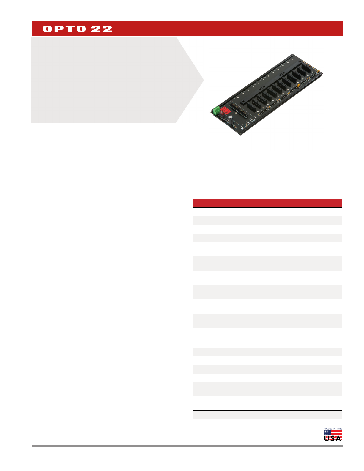
SNAP B-SERIES RACKS
Features
Secure mounting for SNAP I/O modules plus a SNAP brain or
>
on-the-rack SNAP controller
Analog, digital, and serial modules on the same rack
>
Panel or DIN-rail mounting
>
Modules snap into place
>
DESCRIPTION
NOTE: For racks to use with SNAP PAC controllers and brains, see
Opto 22 form #1684, the SNAP PAC Racks Data Sheet.
NOTE: M-series racks (such as the SNAP-M64), used with SNAP Simple
brains and SNAP-UP1-M64 controllers, have been replaced by SNAP
PAC racks. See form #1684.
DATA SHEET
Form 0784-190731
PAGE 1
SNAP B-Series Rack
All SNAP racks offer panel mounting and the option of DIN-rail
mounting. SNAP racks require a 5 VDC power source. SNAP-B4M,
SNAP-B8M, SNAP-B12M, SNAP-B16M, and SNAP-D64RS racks are
Factory Mutual approved.
SNAP B-series mounting racks are designed to hold an intelligent
SNAP I/O processor—either a SNAP brain or an on-the-rack
controller—and several I/O modules.
This rack family includes racks that are compatible with ARCNET and
serial SNAP brains, including those using Modbus® and Profibus®
protocols, and with some Ethernet-based SNAP Ultimate I/O™
on-the-rack controllers and SNAP Ethernet I/O™ brains. For specific
processor compatibility, see “Specifications” on page 3.
Since SNAP analog, digital, and serial I/O modules have the same
footprint, customers using most SNAP B-series racks can mix modules
on the same I/O mounting rack. However, module types, features, and
positions on the rack vary depending on the capabilities of the brain
or on-the-rack controller used. See the brain or controller data sheet
for details.
Field devices are wired directly to the top-mounted removable
connectors on the modules plugged into each rack. SNAP B-series
racks can accommodate up to 4, 8, 12, or 16 modules. The module
and rack design allows modules to simply “snap” on and off the
mounting rack.
SNAP racks use a retention rail locking system that holds modules
securely to the rack. Normally, a hold-down screw is not required.
However, for applications that require additional module security,
SNAP racks have provisions for two 4-40 by ½-inch standard machine
screws to hold each module in position.
MC and MC-P model racks provide an auxiliary screw-type terminal
strip for field wiring common connections such as loop power
distribution. MC racks use a fixed terminal strip, while MC-P racks use
removable connectors for easy maintenance (see enlarged view on
the following page).
Part Numbers
Part Description
SNAP-B4M* 4-module rack
SNAP-B8M* 8-module rack
SNAP-B12M* 12-module rack
SNAP-B16M* 16-module rack
SNAP-B8MC
SNAP-B12MC
SNAP-B16MC
SNAP-B8MC-P
SNAP-B12MC-P
SNAP-B16MC-P
SNAP-D64RS*
SNAP-FUSE7.5AB 7.5-amp fuse, 25-pack
SNAP-FUSE4AB 4-amp fuse, 25-pack
SNAP-FUSE1AB 1-amp fuse, 25-pack
SNAP-TEX-DRC10 SNAP PAC rack DIN-rail adapter clip, 10-pack
SNAP-TEX-REC10N
SNAP-TEX-REC10W
* Factory Mutual (FM) approved
8-module rack with extra terminal block for field
wiring
12-module rack with extra terminal block for field
wiring
16-module rack with extra terminal block for field
wiring
8-module rack with extra terminal block for field
wiring, pluggable
12-module rack with extra terminal block for field
wiring, pluggable
16-module rack with extra terminal block for field
wiring, pluggable
16-module rack for digital-only SNAP Ultimate,
SNAP Ethernet, and SNAP-PDPRS64 Profibus
brains
Narrow end cap for SNAP PAC racks DIN-rail
assemblies, 10-pack
Wide end cap for SNAP PAC racks DIN-rail
assemblies with terminal strips, 10-pack
© 2001–2019 Opto 22. All rights reserved. Dimensions and specifications are subject to change. Brand or product names used herein are trademarks or registered trademarks of their respective companies or organizations.
Page 2
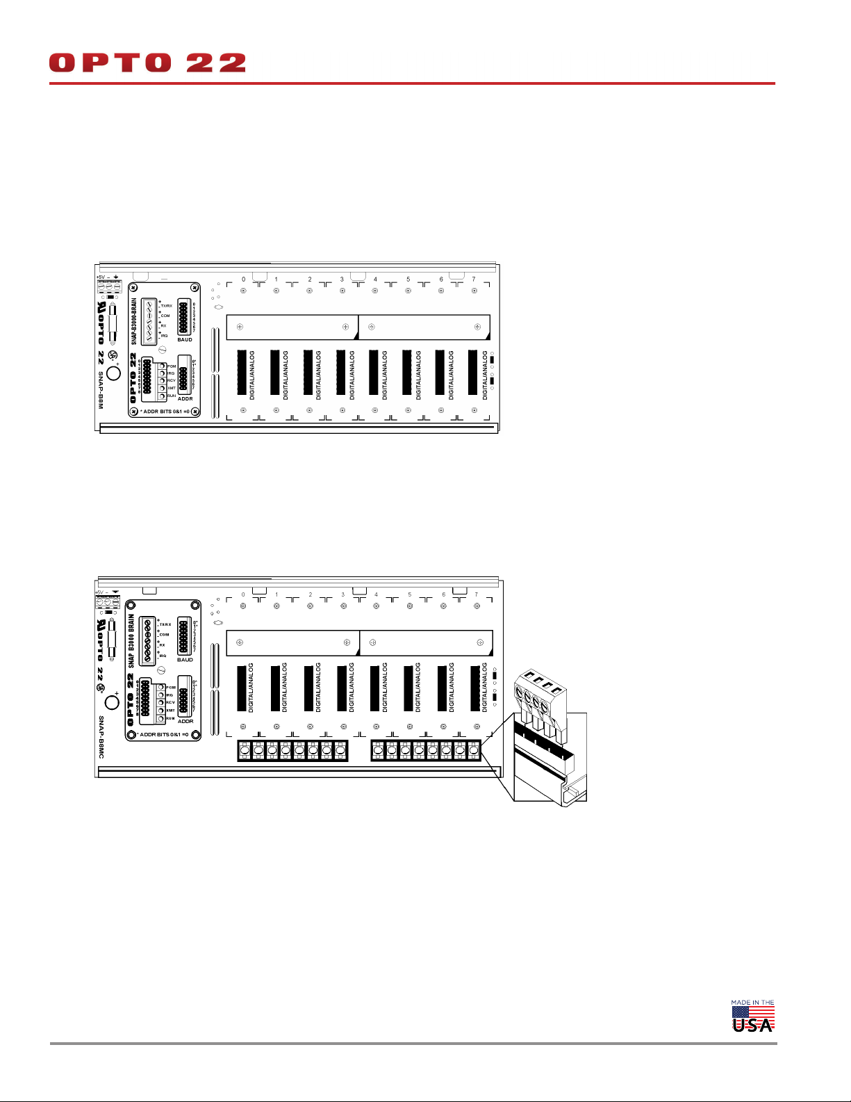
DESCRIPTION (CONTINUED)
SNAP-B8M (8-Module Position I/O Mounting Rack)
Shown with B3000 brain (purchased separately)
DATA SHEET
Form 0784-190731
PAGE 2
SNAP-B8MC (8-Module Position I/O Mounting Rack)
Shown with B3000 brain (purchased separately)
Pluggable connector
for MC-P models
© 2001–2019 Opto 22. All rights reserved. Dimensions and specifications are subject to change. Brand or product names used herein are trademarks or registered trademarks of their respective companies or organizations.
Page 3

SPECIFICATIONS
DATA SHEET
Form 0784-190731
PAGE 3
Part Number Description
1
Power2
Requirements
I/O Processor3
Compatibility
Replacement
Fuse
Operating
Temperature
Relative
Humidity
5.0 to 5.2 VDC
SNAP-B4M 4-module mixed
@ 1.8 Amps
max
SNAP-B8M 8-module mixed
4
4
,
4
5.0 to 5.2 VDC
@ 2.6 Amps
max
5.0 to 5.2 VDC
@ 3.4 Amps
max
5.0 to 5.2 VDC
@ 4.2 Amps
max
5.0 to 5.2 VDC
@ 1.8 Amps
max
SNAP-UP1-ADS
SNAP-B3000-ENET
SNAP-ENET-RTC
B3000
B3000-HA
SNAP-B4
SNAP-B6
SNAP-BRS
SNAP-BRS-HA
SNAP-B3000-
MODBUS
SNAP-UP1-D64
SNAP-ENET-D64
SNAP-PDPRS64
SNAP-FUSE4A
5
or Bel
5HF4
SNAP-FUSE1A
or Buss5
GDC1A
0 to 70 °C
95%,
non-con-
densing
SNAP-B8MC
SNAP-B8MC-P
8-module mixed,
terminal block
8-module mixed,
pluggable terminal block
SNAP-B12M 12-module mixed
SNAP-B12MC
SNAP-B12MC-P
12-module mixed4,
terminal block
12-module mixed
pluggable terminal block
SNAP-B16M 16-module mixed
SNAP-B16MC
SNAP-B16MC-P
SNAP-D64RS
16-module mixed4,
terminal block
16-module mixed4,
pluggable terminal block
16-module digital only
(limited digital functions)
1 “Mixed” means the rack can hold analog, digital, and serial modules. Most Ethernet-based I/O processors handle all these types
of modules; other processors do not. See the processor’s data sheet for details.
2 Power requirements shown are for a rack, a processor, and a full load of 2-channel analog modules (for the SNAP-D64RS, a full
load of 4-channel digital modules). Power requirements for other SNAP modules are higher. See module data sheets.
3 “I/O Processor” means a SNAP brain or on-the-rack controller.
4 Four-channel SNAP digital modules can be used in positions 0–7 only.
5 Manufacturer’s part number (not available through Opto 22).
© 2001–2019 Opto 22. All rights reserved. Dimensions and specifications are subject to change. Brand or product names used herein are trademarks or registered trademarks of their respective companies or organizations.
Page 4
SPECIFICATIONS (CONTINUED)
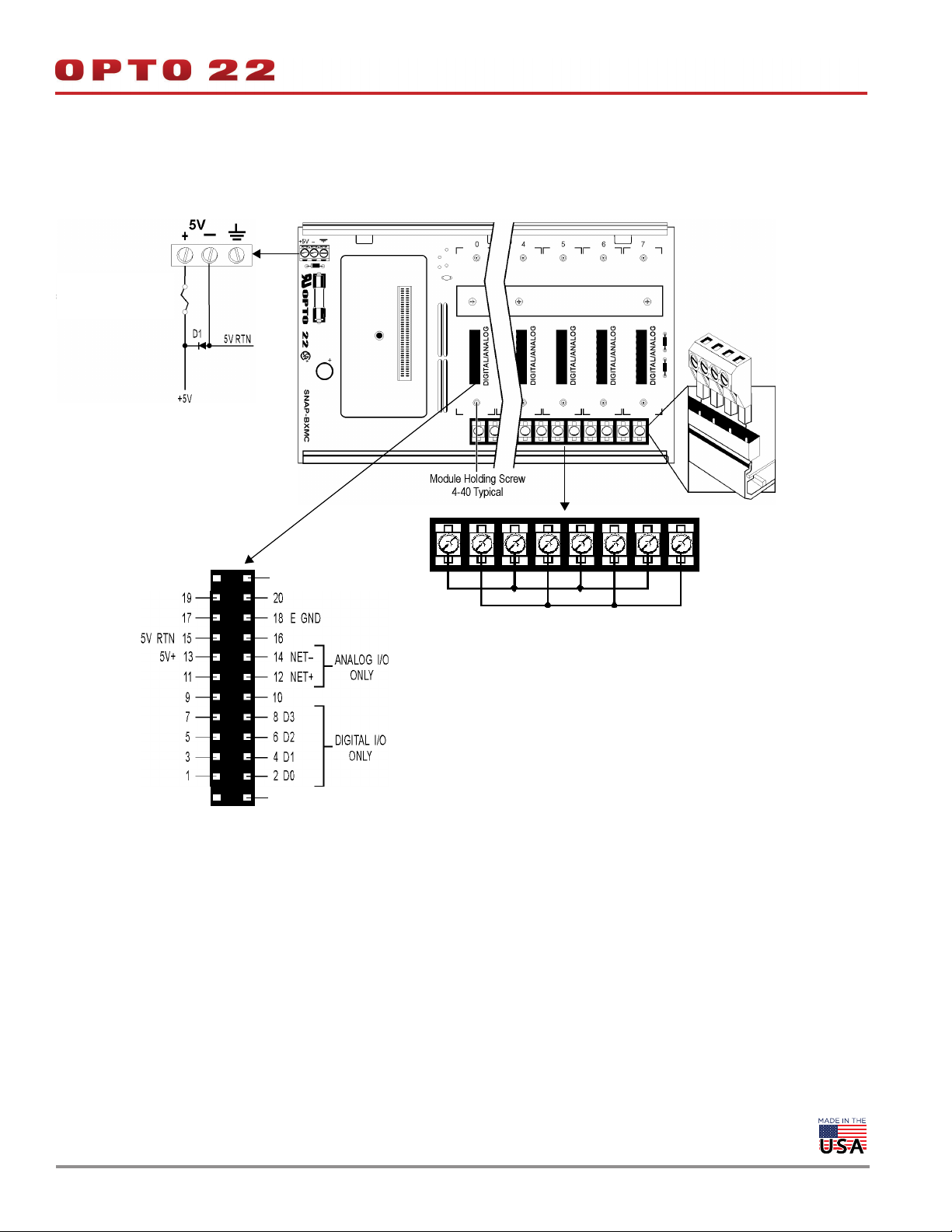
All models:
Power schematic
For fuse part numbers,
see Specifications on
page 3.
DATA SHEET
Form 0784-190731
PAGE 4
MC-P models
only: Pluggable
connector (wire
range 22–14 AWG)
All models: Module mating
connector pinout (female)
IMPORTANT: The mounting rack connector has 24 pins;
the module connector has 20 pins. The extra pins on the
mounting rack connector prevent misalignment of the
module during installation.
Extra pins for alignment
MC and MC-P models only: For detailed
information on terminal strip usage, see page 12
through page 16.
Extra pins for alignment
© 2001–2019 Opto 22. All rights reserved. Dimensions and specifications are subject to change. Brand or product names used herein are trademarks or registered trademarks of their respective companies or organizations.
Page 5
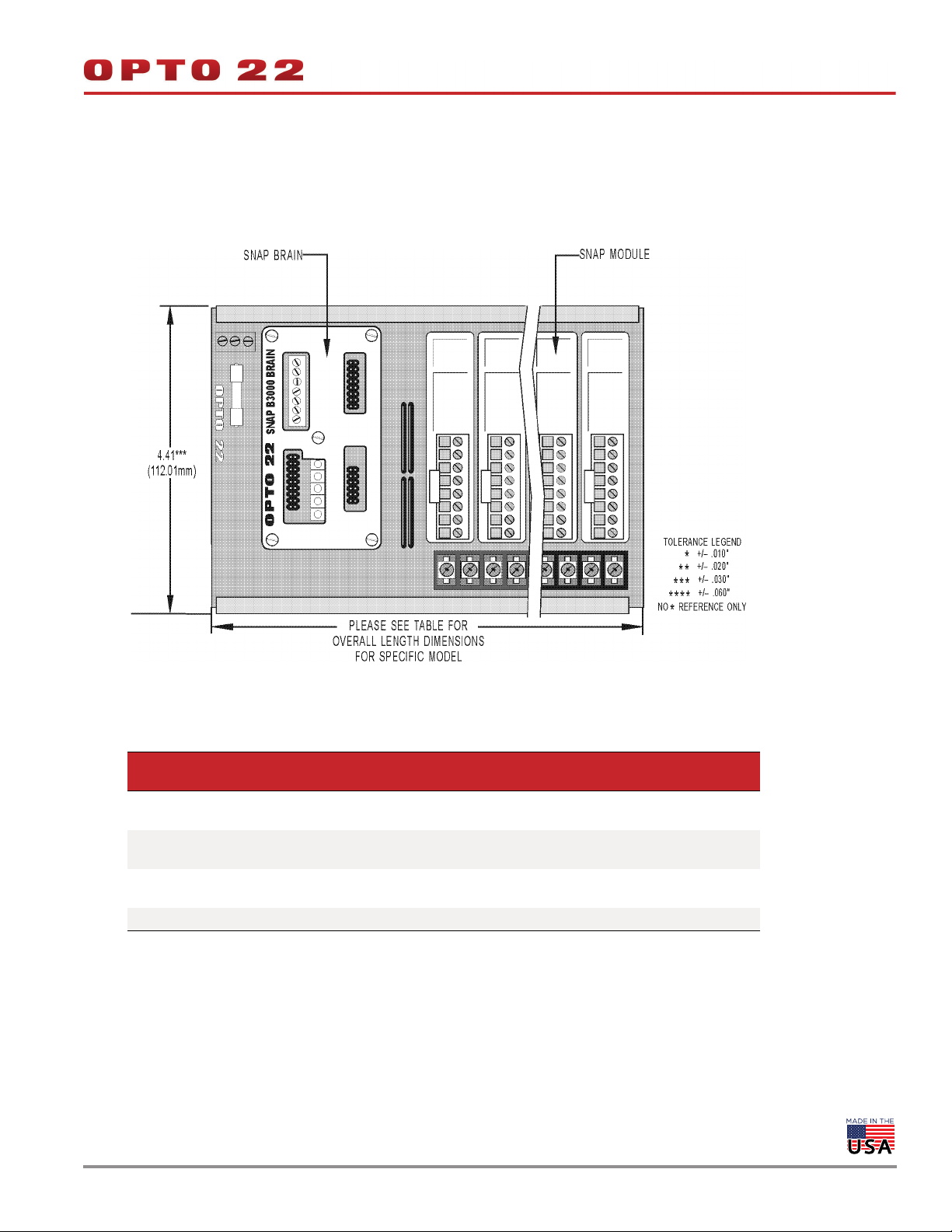
DIMENSIONAL DRAWINGS
Dimensions—SNAP-D64RS Rack and B-Series Racks with Terminal Strips
NOTE: Brain is shown as a sample
for placement only. See page 3
for brain-rack compatibility.
DATA SHEET
Form 0784-190731
PAGE 5
Overall Length Dimensions (SNAP-D64RS and B-series racks with terminal strips)
Part Number Description
SNAP-B8MC
SNAP-B8MC-P
SNAP-B12MC
SNAP-B12MC-P
SNAP-B16MC
SNAP-B16MC-P
SNAP-D64RS 16-module rack, digital only 4.41 112.01 15.25 387.35
© 2001–2019 Opto 22. All rights reserved. Dimensions and specifications are subject to change. Brand or product names used herein are trademarks or registered trademarks of their respective companies or organizations.
8-module rack for other brains,
with terminal block
12-module rackfor other brains,
with terminal block
16-module rackfor other brains,
with terminal block
Width
(inches)
4.41 112.01 9.25 234.95
4.41 112.01 12.25 311.15
4.41 112.01 15.25 387.35
Width
(mm)
Length
(inches)
Length
(mm)
Page 6

DIMENSIONAL DRAWINGS (CONTINUED)
Dimensions—B-Series Racks Without Terminal Strips
DATA SHEET
Form 0784-190731
PAGE 6
Overall Length Dimensions (B-series racks without terminal strips)
Part Number Description
SNAP-B4M 4-module rack 3.91 99.31 6.24 158.41
SNAP-B8M 8-module rack 3.91 99.31 9.24 234.70
SNAP-B12M 12-module rack 3.91 99.31 12.24 310.90
SNAP-B16M 16-module rack 3.91 99.31 15.24 387.10
Width
(inches)
Width
(mm)
Length
(inches)
Length
(mm)
© 2001–2019 Opto 22. All rights reserved. Dimensions and specifications are subject to change. Brand or product names used herein are trademarks or registered trademarks of their respective companies or organizations.
Page 7

DIMENSIONAL DRAWINGS (CONTINUED)
SNAP-D64RS Rack and B-Series Racks with Terminal Strips:
Right Side View with DIN-Rail Option Installed
DATA SHEET
Form 0784-190731
PAGE 7
Processor Height* Processor Part Number Rack
SNAP-UP1-ADS
SNAP-B3000-ENET
4.12 in. (104.6 mm)
3.70 in. (95.9 mm)
* Height listed is from the processor’s mounting surface to the highest part of the processor. Height does not include wiring or cables.
© 2001–2019 Opto 22. All rights reserved. Dimensions and specifications are subject to change. Brand or product names used herein are trademarks or registered trademarks of their respective companies or organizations.
SNAP-ENET-RTC
SNAP-UP1-D64
SNAP-ENET-D64
B3000
SNAP-B4
SNAP-B6
SNAP-BRS
B3000-HA
SNAP-BRS-HA
SNAP-B3000-MODBUS
B-series
SNAP-D64RS
B-series
Page 8

DIMENSIONAL DRAWINGS (CONTINUED)
B-Series Racks Without Terminal Strips:
Right Side View with DIN-Rail Option Installed
DATA SHEET
Form 0784-190731
PAGE 8
Processor Height* Processor Part Number
4.12 in. (104.6 mm)
3.70 in. (95.9 mm)
* Height listed is from the processor’s mounting surface to the highest part
of the processor. It does not include wiring or cables.
© 2001–2019 Opto 22. All rights reserved. Dimensions and specifications are subject to change. Brand or product names used herein are trademarks or registered trademarks of their respective companies or organizations.
SNAP-UP1-ADS
SNAP-B3000-ENET
B3000
SNAP-B4
SNAP-B6
B3000-HA
SNAP-ENET-RTC
SNAP-BRS
SNAP-BRS-HA
SNAP-B3000-MODBUS
Page 9

MOUNTING
DATA SHEET
Form 0784-190731
PAGE 9
NOTE: If you are not using hold-down screws, the SNAP rack assembly
should be mounted horizontally.
Use the following steps to mount racks as shown in the diagrams on
the next two pages.
Preferred Method: Template
(Product on site)
1. Use SNAP rack mounting extrusion as template.
2. Be sure to use the diagrams on the next two pages to determine
required product and option clearances.
Center-to-Center Length (All Models)
Part Number Description
SNAP-B4M 4-module rack 4.01 in. 2
SNAP-B8M
SNAP-B8MC
SNAP-B8MC-P
SNAP-B12M
SNAP-B12MC
SNAP-B12MC-P
SNAP-B16M
SNAP-B16MC
SNAP-B16MC-P
SNAP-D64RS
8-module rack 3.51 in. 3
12-module rack 5.01 in. 3
16-module rack 4.34 in. 4
Center-to-Center
Length
Alternate Method: Prefabrication of Panels
(No product on site)
Mounting holes are in sets of two, located on lower left and upper
right with respect to a center line (CL).
1. Using the diagrams on the next two pages, determine CL1
mounting hole positions. (CL1 is located on the left side of all
SNAP rack mounting extrusions.)
2. Use the center-to-center length specification table below to
determine the offset between center lines and the number of
center line positions for each model.
3. Repeat the process for each center line position.
Number of Center
Positions
© 2001–2019 Opto 22. All rights reserved. Dimensions and specifications are subject to change. Brand or product names used herein are trademarks or registered trademarks of their respective companies or organizations.
Page 10

MOUNTING (CONTINUED)
SNAP-D64RS Rack and B-Series Racks with Terminal Strips:
Typical Plain View of SNAP Mounting Extrusion
DATA SHEET
Form 0784-190731
PAGE 10
See instructions and table on page 9.
© 2001–2019 Opto 22. All rights reserved. Dimensions and specifications are subject to change. Brand or product names used herein are trademarks or registered trademarks of their respective companies or organizations.
Page 11

MOUNTING (CONTINUED)
B-Series Racks Without Terminal Strips:
Typical Plain View of SNAP Mounting Extrusion
DATA SHEET
Form 0784-190731
PAGE 11
See instructions and table on page 9.
© 2001–2019 Opto 22. All rights reserved. Dimensions and specifications are subject to change. Brand or product names used herein are trademarks or registered trademarks of their respective companies or organizations.
Page 12

WIRING DIAGRAMS—B-SERIES MODELS WITH TERMINAL STRIPS
Terminal Strip Usage—Digital
Example: Digital Input Using Terminal Strip
NOTE: Consult the SNAP module
data sheet for your specific
module for additional wiring
DATA SHEET
Form 0784-190731
PAGE 12
Example: Digital AC Output Using Terminal Strip
© 2001–2019 Opto 22. All rights reserved. Dimensions and specifications are subject to change. Brand or product names used herein are trademarks or registered trademarks of their respective companies or organizations.
Page 13

WIRING DIAGRAMS—B-SERIES MODELS WITH TERMINAL STRIPS
Terminal Strip Usage—Digital (continued)
Example: Digital DC Output (Sourcing) Using Terminal Strip
NOTE: Consult the SNAP module
data sheet for your specific
module for additional wiring
DATA SHEET
Form 0784-190731
PAGE 13
Example: Digital DC Output (Sinking) Using Terminal Strip
© 2001–2019 Opto 22. All rights reserved. Dimensions and specifications are subject to change. Brand or product names used herein are trademarks or registered trademarks of their respective companies or organizations.
Page 14

WIRING DIAGRAMS—B-SERIES MODELS WITH TERMINAL STRIPS
Terminal Strip Usage—Analog
Example: Analog Input (Current: Negative) Using Terminal Strip
NOTE: Consult the SNAP module
data sheet for your specific
module for additional wiring
DATA SHEET
Form 0784-190731
PAGE 14
Example: Analog Input (Current: Positive) Using Terminal Strip
© 2001–2019 Opto 22. All rights reserved. Dimensions and specifications are subject to change. Brand or product names used herein are trademarks or registered trademarks of their respective companies or organizations.
Page 15

WIRING DIAGRAMS—B-SERIES MODELS WITH TERMINAL STRIPS
Terminal Strip Usage—Analog (continued)
Example: Analog Output (4–20 mA Current: Sourcing) Using Terminal Strip
NOTE: Consult the SNAP module
data sheet for your specific
module for additional wiring
DATA SHEET
Form 0784-190731
PAGE 15
Example: Analog Output (4–20 mA Current: Sinking) Using Terminal Strip
© 2001–2019 Opto 22. All rights reserved. Dimensions and specifications are subject to change. Brand or product names used herein are trademarks or registered trademarks of their respective companies or organizations.
Page 16

WIRING DIAGRAMS—B-SERIES MODELS WITH TERMINAL STRIPS
Terminal Strip Usage—Analog (continued)
Example: Analog Input (Voltage) Using Terminal Strip
NOTE: Consult the SNAP module
data sheet for your specific
module for additional wiring
DATA SHEET
Form 0784-190731
PAGE 16
© 2001–2019 Opto 22. All rights reserved. Dimensions and specifications are subject to change. Brand or product names used herein are trademarks or registered trademarks of their respective companies or organizations.
 Loading...