

Page 1
BRAINS
SNAP
DIGITAL
DAT A SHEET
Form 955-050221
Description
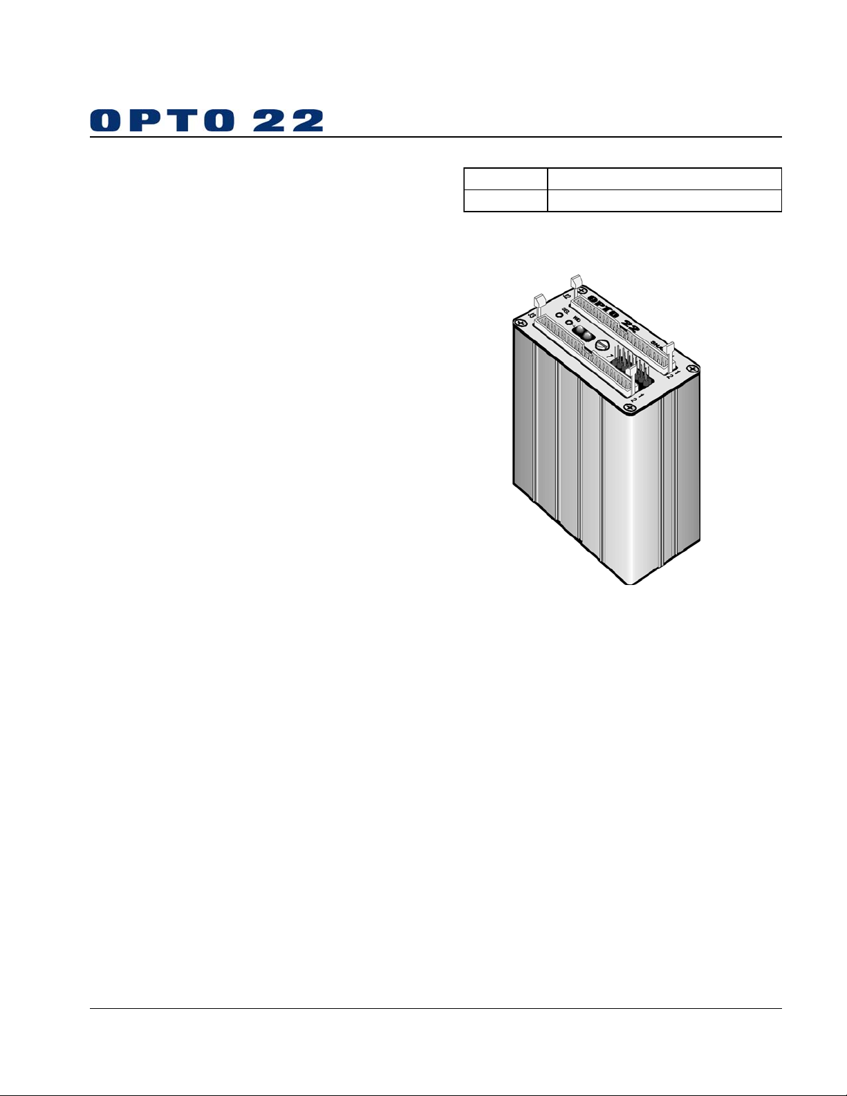
The SNAP-B4 is a high-performance digital brain
used to connect and control up to 32 channels of
digital I/O using Opto 22’s SNAP “B Series” I/O
mounting racks and the Pamux bus. The SNAP-B4,
combined with Opto 22’s AC28 interface card and a
host PC, provides the world’s fastest digital I/O.
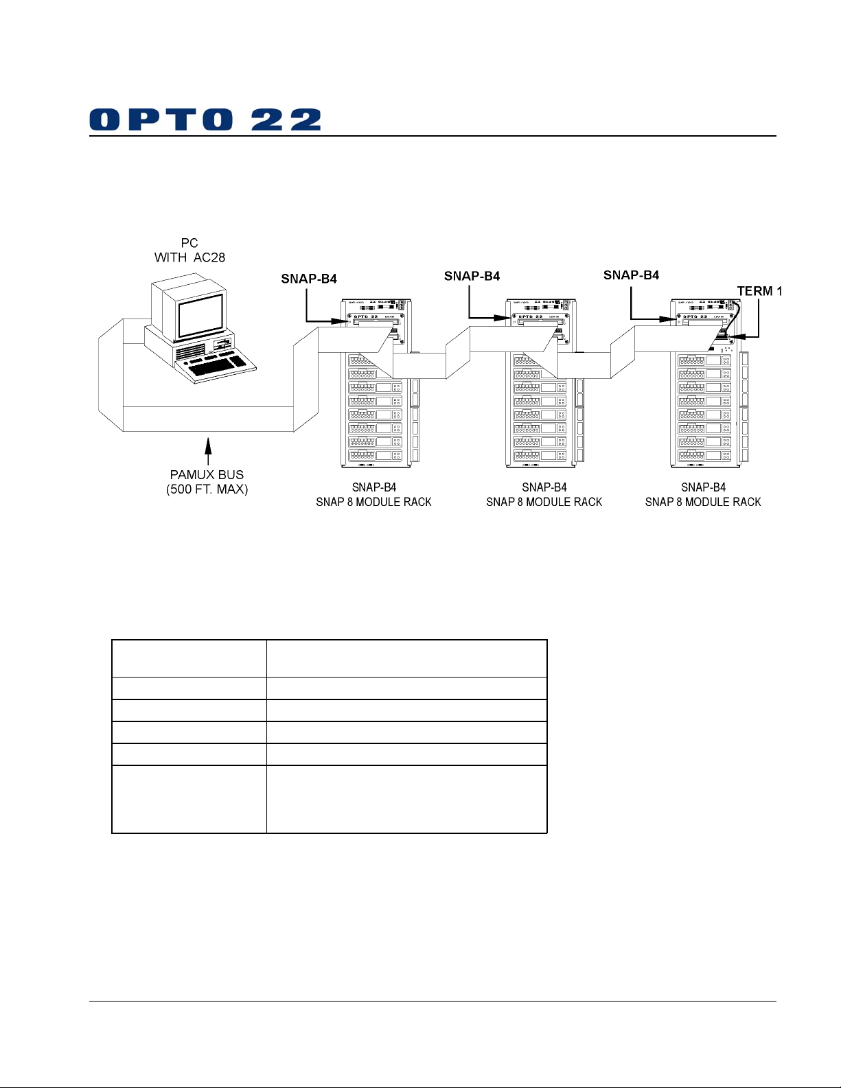
The SNAP-B4 communicates over a 50-pin flat
ribbon cable (Pamux bus) and can be located
up to 500 feet away from the host processor.
The Pamux bus has 64 possible addresses.
Each group of eight I/O points occupy one
address, therefore the Pamux bus can control up to
512 digital and analog I/O points. Each SNAP-B4
brain controls 32 digital I/O points and occupies
four consecutive addresses on the Pamux bus.
For additional technical information about Pamux,
please refer to Opto 22 form number 726.
page 1/6
Part Number Description
SNAP-B4 High-speed Digital Brain, Pamux Protocol
Features
PAMUX Bus
Configurable Watchdog Timer
Digital Only
Very High Speed
500 I/O Points
500 Microseconds
Cable Lengths up to 500 Feet
SNAP-B4 Digital Brain
Page 2
BRAINS
SNAP
DIGITAL
DAT A SHEET
Form 955-050221
page 2/6
System Architecture
Specifications
General
Power Requirements
Operating Temperature 0° C to 70° C, 95% humidity, non-condensing
Communications Interface Pamux Bus; two 50-pin connectors
Range: (Multidrop mode) Up to 500 feet
LED Indicators SEL (address selected), WD (watchdog timeout)
Jumpers
5.0 VDC ± 0.1 VDC @ 1.0A max.
(If Term1 installed add 0.5A)
0 - 3 Address
4 - 5 Watchdog Timer Function
6 Reset Level
7 Effect of Reset on Channel 0 Watchdog
Page 3

BRAINS
SNAP
DIGITAL
DAT A SHEET
Form 955-050221
Specifications
B4 Jumpering
Please refer to the tables on this page for
SNAP-B4 jumper functions.
Notes:
1. The B4 can only be jumpered for addresses
that are either zero or a multiple of four.
2. The B4’s watchdog timeout value is a function
of hardware and is not user-configurable. An
on-board RC circuit sets the watchdog
between 1.0 and 2.25 seconds.
page 3/6
Address Jumpers
Watchdog Timer Jumpers
Jumper 4 Jumper 5 Watchdog Action
LED DescriptionsLED Descriptions
LED Descriptions
LED DescriptionsLED Descriptions
LED Description
WD Watchdog timer has expired
Address lines on Pamux bus
ADR
match jumper address
In In Active No Action
Out In Active Activate Channel 0
In Out Active Deactivate all Channels
Out Out Active
Jumper 6 Jumper 7 Action
Out X Logic Low Reset
In X Logic High Reset
Jumper 7 Action
Out
Installed
Installed
Reset has no effect on Channel 0
watchdog operation
Reset Active before Watchdog Timeout:
All outputs off until Reset off, then
normal watchdog function
Watchdog Timeout then Reset Active:
Normal Watchdog function; subsequent
Reset has no effect
Activate 0,
all others Deactivate
Page 4

BRAINS
SNAP
DIGITAL
DAT A SHEET
Form 955-050221
Specifications
B4 I/O Mapping
I/O on the SNAP-B4 is divided into four addresses of digital I/O, each with eight channels as follows:
First two module positions (0-1): The 8 digital channels of B4 Base Address + 0.
Second two module positions (2-3): The 8 digital channels of B4 Base Address + 1.
Third two module positions (4-5): The 8 digital channels of B4 Base Address + 2.
Fourth two module positions (6-7): The 8 digital channels of B4 Base Address + 3.
If a SNAP-B4 brain is configured at address 12, the digital addresses used by that SNAP-B4 would be 12, 13,14,
and 15.
page 4/6
SNAP I/O Rack
Page 5

BRAINS
SNAP
DIGITAL
DAT A SHEET
Form 955-050221
Dimensional Drawing
page 5/6
B4 Brain
Page 6
BRAINS
SNAP
DIGITAL
DAT A SHEET
Form 955-050221
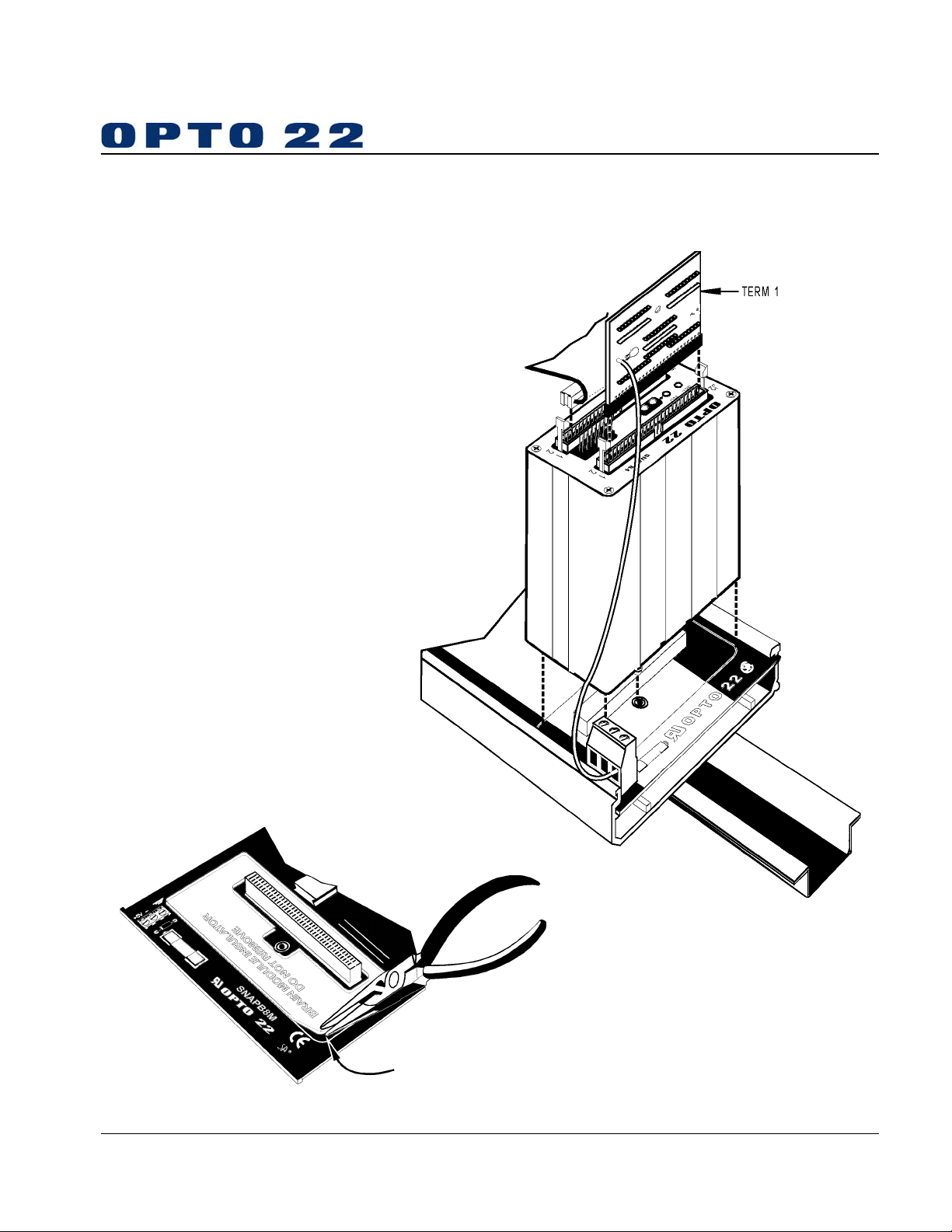
Assembly
Brain and Mounting Rack
To install SNAP-B4 onto B Series rack:
1. Turn off power to rack assembly.
2. If a plastic brain insulator is present on
your mounting rack, remove as shown
below
3. Align the brain connector with mating
connector on rack.
4. Seat brain onto connector.
5. Use integral hold-down screw to secure
in position. Do not overtighten.
6. If Term 1 is used install as shown.
Note: Term 1 is only for the last physical
connection to Pamux bus.
page 6/6
To remo ve SNAP-B4 from B Series rack:
1. Turn off power to rack assembly.
2. Loosen integral hold-down screw
on SNAP-B4 processor.
3. Pull up on processor.
© 1997–2001 Opto 22. All rights reserved. All trademarks, trade names, logos, and service marks referenced herein belong to their respective companies.
 Loading...