

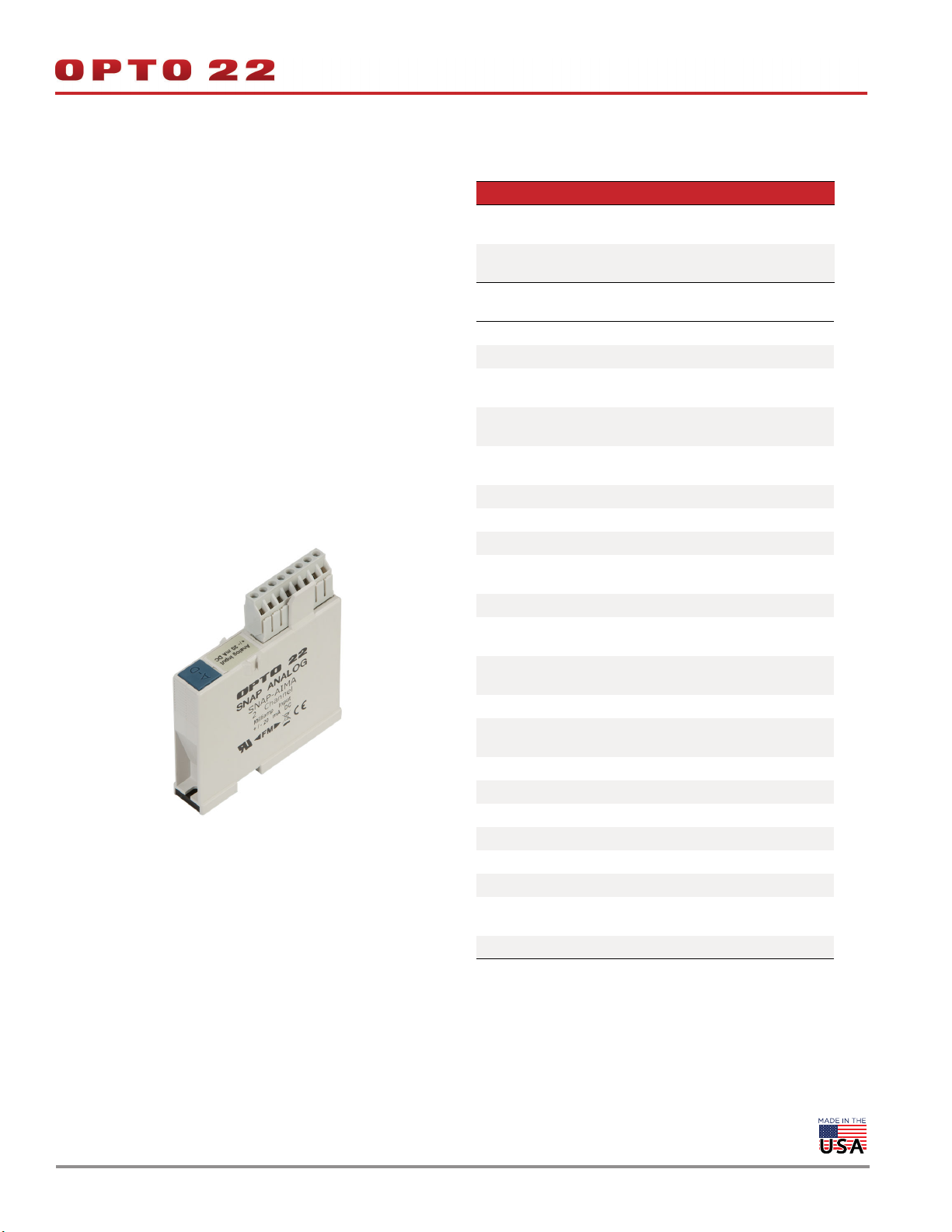
SNAP ANALOG INPUT MODULES
Features
Resolution = 0.004% of nominal range
>
Two, 4, 8, or 32 single-ended inputs per module
>>
Out-of-range indication
>
Factory calibrated; no user adjustment necessary
>
DATA SHEET
Form 1065-191230
PAGE 1
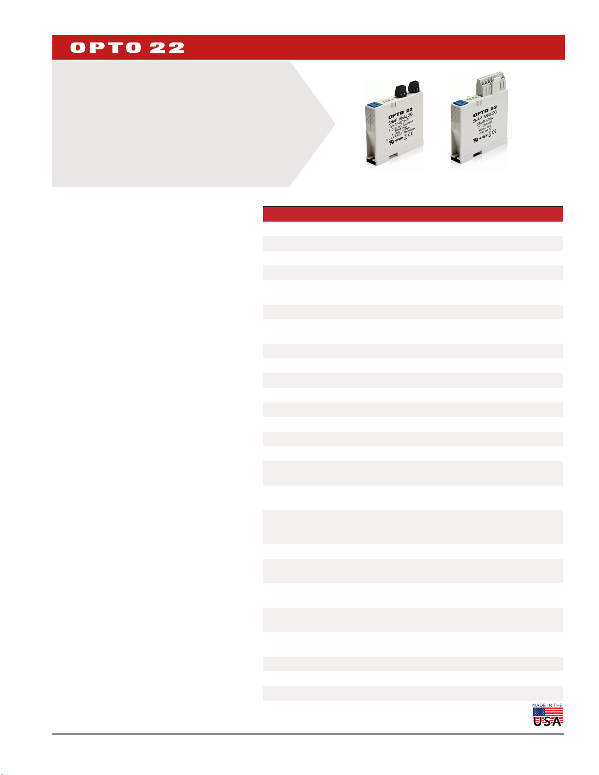
SNAP Analog Input Modules
Part Numbers
DESCRIPTION
SNAP I/O analog input modules are part of Opto 22’s
SNAP PAC System. All of these modules mount on a SNAP
PAC rack with a SNAP PAC brain or R-series controller,
either a standard wired model or a Wired+Wireless™
model.
A minimum number of SNAP module types support a full
range of analog input requirements. These
software-configurable modules handle a wide variety of
signal levels. They provide high resolution (0.004% of
nominal range) for precise signal levels, as well as
multiple-channel packaging. All SNAP analog modules
are factory calibrated and individually tested. Part
numbers ending in -FM are Factory Mutual approved.
SNAP analog input modules have an on-board
microprocessor to provide module-level intelligence,
which makes them an ideal choice for Original Equipment
Manufacturers (OEMs). For additional information about
the standalone operation of SNAP analog modules, see
Opto 22 form #0876, SNAP I/O Module Integration Guide.
Notes for legacy hardware: Some of these modules
also work with older Opto 22 I/O processors (brains or
on-the-rack controllers) and M-series or B-series racks. To
check processor compatibility, see the table on page 3.
Specifications begin on page 4. For dimensional
drawings, see pages 40–51.
IMPORTANT: Any system using analog sensors and input
modules should be calibrated annually for analog signals.
For I/O units on a SNAP PAC System, use the PAC Control™
commands “Calculate and Set Offset” and “Calculate and
Set Gain.” For other Ethernet-based I/O units, you can also
use PAC Manager™ software to calculate and set offset
and gain.
Isolation
All SNAP analog input modules are isolated from all other
modules and from the SNAP I/O processor. The modules
Part Description Page
SNAP-AIARMS 2-channel 0 to 10 amp RMS AC/DC input 4
SNAP-AIMA 2-channel analog current input, -20 to +20 mA 6
SNAP-AIMA-4 4-channel analog current input -20 to +20 mA 6
SNAP-AIMA-8 8-channel analog current input -20 to +20 mA 9
SNAP-AIMA-32
SNAP-AIMA-32-FM*
SNAP-AIRATE 2-channel 0–25,000 Hz analog rate input 13
SNAP-AIR40K-4
SNAP-AIR400K-8 8-channel analog resistor/thermistor input, 400 K Ohms 16
SNAP-AIRTD 2-channel 100 ohm platinum RTD input 20
SNAP-AIRTD-1K 2-channel 1000 ohm platinum RTD input 20
SNAP-AIRTD-10 2-channel 10 ohm copper RTD input 20
SNAP-AIRTD-8U 8-channel multifunction RTD/resistance input 22
SNAP-AICTD 2-channel analog temperature input, ICTD 25
SNAP-AICTD-4 4-channel analog temperature input, ICTD 25
SNAP-AICTD-8 8-channel analog temperature input, ICTD 27
SNAP-AITM
SNAP-AITM-2
SNAP-AITM-8
SNAP-AITM-8-FM*
SNAP-AIVRMS 2-channel 0 to 250 V RMS AC/DC input 31
SNAP-AIV
SNAP-AIV-4
SNAP-AIV-8
SNAP-AIV-32
SNAP-AIV-32-FM*
SNAP-AIMV2-4 4-channel -50 to +50 mV input or -25 to +25 mV input 37
SNAP-AIMV-4 4-channel -150 to +150 mV input or -75 to +75 mV input 38
* Factory Mutual approved
32-channel analog current input -20 to +20 mA 10
4-channel analog resistor/thermistor input, 40 K Ohms,
20 K Ohms, 10 K Ohms, or 5 K Ohms
2-channel analog type E, J, or K thermocouple or -150
to +150 mV input or -75 to +75 mV input
2-channel analog type B, C, D, G, N, T, R, or S thermocouple or -50 to +50 mV DC or -25 to +25 mV DC input
8-channel B, C, D, E, G, J, K, N, R, S, or T thermocouple or -75 to +75 mV, -50 to +50 mV, or -25 to +25 mV
input
2-channel analog voltage input -10 to +10 VDC or -5 to
+5 VDC
4-channel analog voltage input -10 to +10 VDC or -5 to
+5 VDC
8-channel analog voltage input -10 to +10 VDC or -5 to
+5 VDC
32-channel analog voltage input -10 to +10 VDC or -5
to +5 VDC
15
28
30
30
32
32
34
35
© 2001–2019 Opto 22. All rights reserved. Dimensions and specifications are subject to change. Brand or product names used herein are trademarks or registered trademarks of their respective companies or organizations.

DATA SHEET
Form 1065-191230
PAGE 2
in this data sheet do not have channel-to-channel isolation, however.
(If you need isolated analog modules, see Opto 22 form #1182.)
Transformer isolation prevents ground loop currents from flowing
between field devices and causing noise that produces erroneous
readings. Ground loop currents are caused when two grounded field
devices share a connection, and the ground potential at each device
is different.
Isolation also protects sensitive control electronics from industrial field
signals.
IMPORTANT: Since these analog input modules provide multiple
single-ended input channels with a common reference, the channels
are not isolated from each other. (See Opto 22 form #1182 for isolated
modules.)
Bipolar and Unipolar Input Modules
Most SNAP analog input modules are considered to be bipolar, which
means the range extends equal amounts above and below zero. An
example of this is the SNAP-AIV module, which has a range of -10 to
+10 VDC.
Some modules are considered unipolar, which means the range starts
or ends at zero. For example, the SNAP-AIVRMS module has a range of
0 to 250 VAC because AC current cannot be negative.
Nominal Range and Over-range Limits
All SNAP analog input modules have a nominal range for the field
signal and most support a 10% over-range limit. The nominal range is
the normal range of the field signal for the module or point
configuration. The over-range limit is the maximum valid field signal
the module or point configuration can read outside of the nominal
range. For example, the over-range limits for the SNAP-AIV are -11 and
+11 VDC, and for the SNAP-AIVRMS, the over-range limit is 275 VAC.
Some modules or point configurations do not support field signals
outside of the nominal range. For example, points configured as
temperature inputs (thermocouple, RTD, ICTD) do not support
over-range readings.
When the field signal is outside of the over-range limits of the
module, the brain will not be able to determine if the value is too high
or too low, so it will return an "out of range" value of -32768.0
Over-range limits only apply to input modules. Output modules are
limited to their nominal ranges.
© 2001–2019 Opto 22. All rights reserved. Dimensions and specifications are subject to change. Brand or product names used herein are trademarks or registered trademarks of their respective companies or organizations.
DATA SHEET
Form 1065-191230
PAGE 3
INSTALLATION
Note module and processor compatibility in the following table:
Modules Compatible I/O Processors
32-channel inputs
8-channel inputs
SNAP-AIRTD-10
SNAP-AIRTD-1K
4-channel inputs
2-channel inputs
(except
SNAP-AIRTD-10 and
SNAP-AIRTD-1K)
All modules can be used with SNAP PAC racks and can be placed in
any position on the rack. Two- and four-channel modules (except the
SNAP-AIRTD-10 and SNAP-AIRTD-1K) can also be used with legacy
SNAP M-series and B-series mounting racks. (For more information on
using legacy hardware, see form #1688, the SNAP PAC System
Migration Technical Note.)
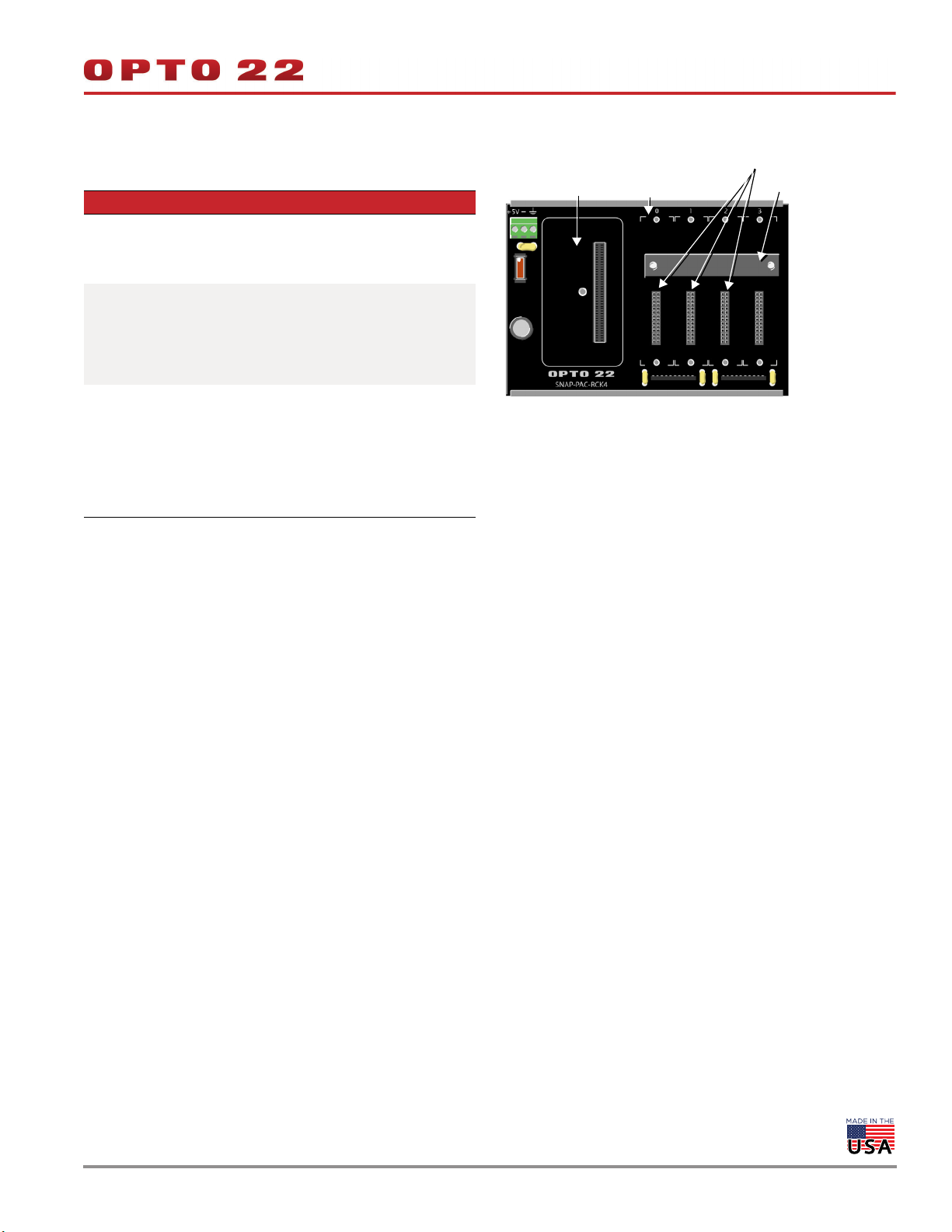
Modules snap securely into place in the row of connectors on the
mounting rack. Each module connector has a number. Analog input
modules and other types of SNAP I/O modules are mounted on the
module connectors starting at module position zero.
Modules require a special tool (provided) for removal.
SNAP PAC R-series controllers and SNAP
PAC brains, including Wired+Wireless models
SNAP PAC R-series controllers and SNAP
PAC brains, including Wired+Wireless models
Also the following legacy brains:
SNAP Ethernet, SNAP Simple, SNAP Ultimate; SNAP-DNP-ASDS; SNAP OEM
SNAP PAC R-series controllers and SNAP
PAC brains, including Wired+Wireless models
Also the following legacy brains:
SNAP Ethernet, SNAP Simple, SNAP Ultimate; SNAP-DNP-ASDS; SNAP OEM; serial
SNAP brains (B3000, Modbus, Profibus);
B3000-HA; B6
The following diagram shows part of a SNAP PAC mounting rack.
Processor
connector
Module
position zero
Module connectors
Retention bar
1. Place the rack so that the module connector numbers are
right-side up, with zero on the left, as shown in the diagram
above. (If your rack has screw connectors, the screw connectors
will be at the bottom.)
2. Position the module over the module connector, aligning the
small slot at the base of the module with the retention bar on the
rack. When positioning modules next to each other, be sure to
align the male and female module keys at the tops of the
modules before snapping a module into position.
3. With the module correctly aligned, push on the module to snap it
into place.
4. Use standard 4-40 x 1/2 truss-head Phillips hold-down screws to
secure both sides of each module.
CAUTION: Do not over-tighten screws. See Specifications.
5. Follow the wiring diagrams beginning on page 4 to attach
modules to the devices they monitor. Most modules accept 22 to
14 AWG wire; the SNAP-AITM-8 accepts a maximum of two solid
18 AWG wires.
For faster, easier field wiring installation and maintenance, use
SNAP TEX cables and breakout boards. See Opto 22 form #1756, the
SNAP TEX Cables & Breakout Boards Data Sheet, for compatibility and
specifications.
© 2001–2019 Opto 22. All rights reserved. Dimensions and specifications are subject to change. Brand or product names used herein are trademarks or registered trademarks of their respective companies or organizations.
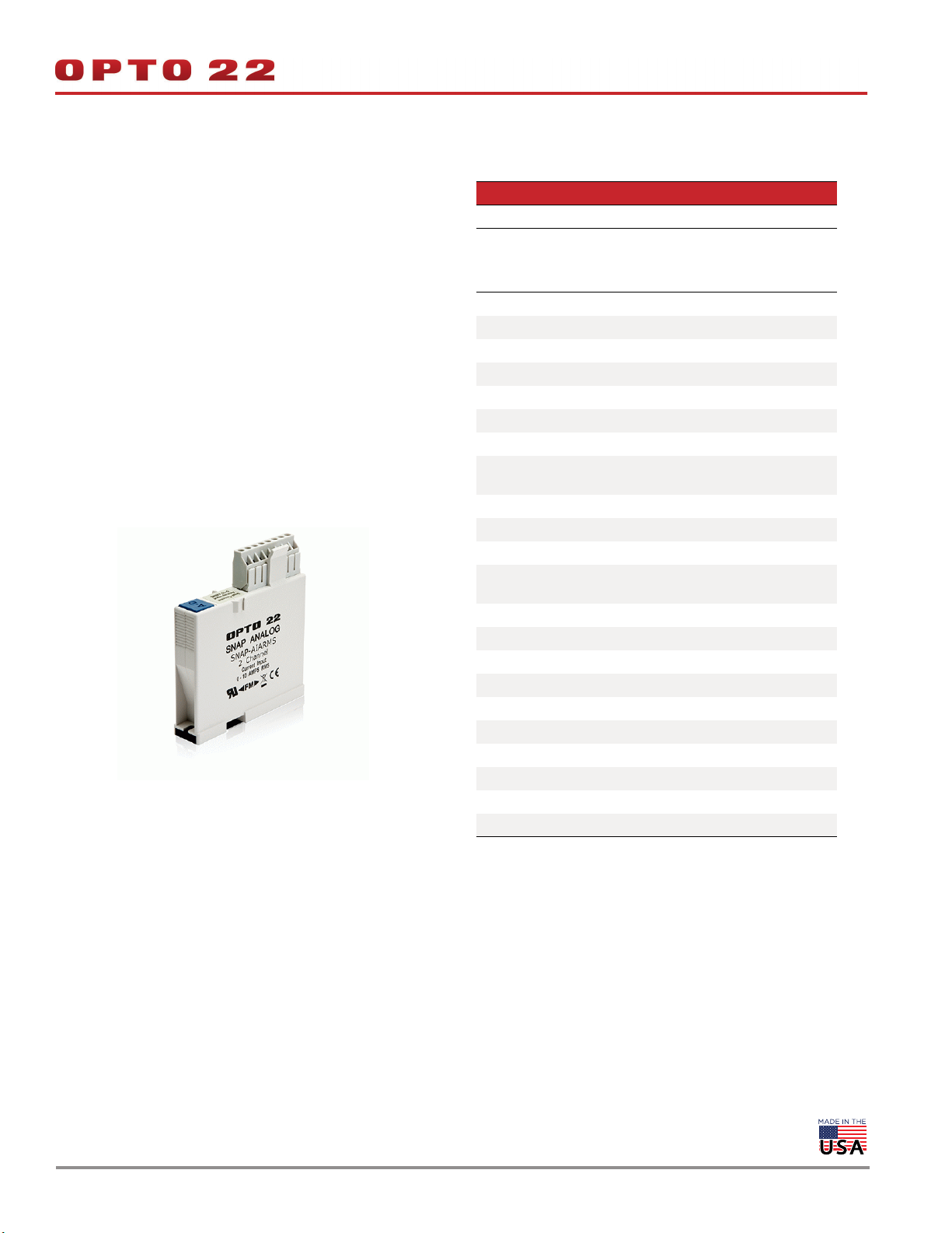
0 TO 10 AMP RMS AC/DC INPUT MODULE
DATA SHEET
Form 1065-191230
PAGE 4
SNAP-AIARMS
Description
The SNAP-AIARMS module provides an input range of 0 to 10 amps
RMS AC/DC. An ideal input is the 5-amp secondary of a standard
current transformer used to monitor AC line current.
The SNAP-AIARMS module may be used to monitor AC current to
greater than a 100-amp range, using a current transformer of suitable
ratio.
If you need a module with channel-to-channel isolation, see form
#1182, the SNAP Isolated Analog Input Modules Data Sheet.
Wiring diagrams are on the following page.
Part Number Description
SNAP-AIARMS Two-channel 0 to 10 amp RMS AC/DC input
Specifications
Input Range 0 to 10 amp RMS AC/DC
Input Over-Range To 11 amps
Input Resistance 0.005 ohms
Maximum Input 11 amps AC/DC
Accuracy (AC) ±8 mA and ±0.2% reading
Resolution 400 microamps
DC Reversal ±16 mA (0.16%)
Input Response Time
(Step Change)
Data Freshness (Max) 32.3 ms
DC Common Mode Rejection >-120 dB
AC Common Mode Rejection >-120 dB at 60 Hz
Maximum Operating Common
Mode Voltage
Isolation 1500 V
Power Requirements 5 VDC (±0.15 V) at 170 mA
Operating Temperature -20 °C to 70 °C
Storage Temperature -40 °C to 85 °C
Humidity 5-95%, non-condensing
Wire size 22 to 14 AWG
Torque, hold-down screws 4 in-lb (0.45 N-m)
Torque, connector screws 5.26 in-lb (0.6 N-m)
Agency Approvals UL, FM, CE, RoHS, DFARS
Warranty Lifetime
63.2% (158 V) in 50 mS
99% (248 V) in 75 mS
250 V
© 2001–2019 Opto 22. All rights reserved. Dimensions and specifications are subject to change. Brand or product names used herein are trademarks or registered trademarks of their respective companies or organizations.
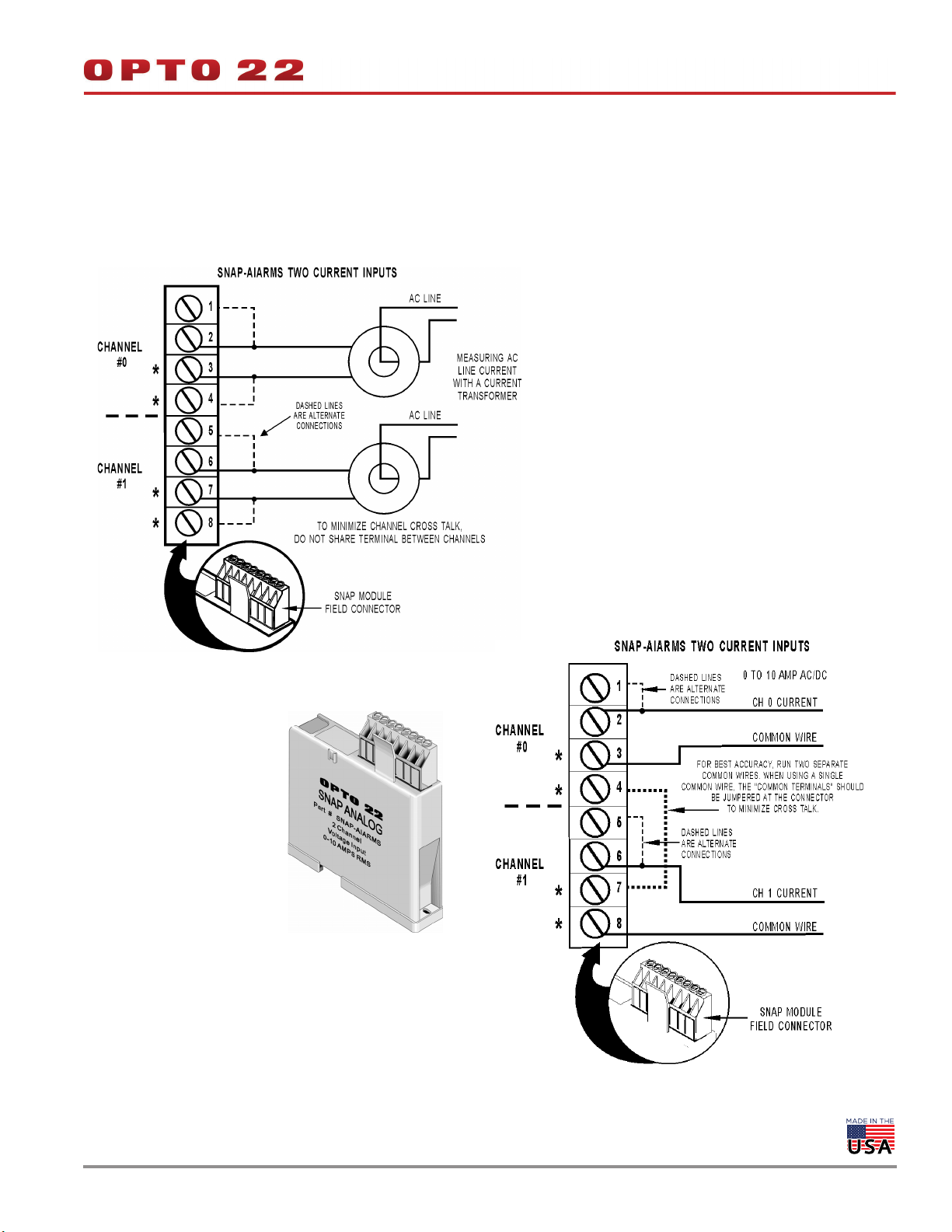
0 TO 10 AMP RMS AC/DC INPUT MODULE (CONTINUED)
SNAP-AIARMS Wiring Diagrams
Two possible wiring diagrams are shown below.
* Terminals 3, 4, 7, and 8 share a common
connection inside the module. Make sure
you observe polarity when connecting the
second channel. To avoid a potentially
hazardous short, double-check wiring before
turning on the current to be monitored.
DATA SHEET
Form 1065-191230
PAGE 5
© 2001–2019 Opto 22. All rights reserved. Dimensions and specifications are subject to change. Brand or product names used herein are trademarks or registered trademarks of their respective companies or organizations.
CURRENT INPUT MODULE, -20 mA TO +20 mA, TWO OR FOUR CHANNELS
DATA SHEET
Form 1065-191230
PAGE 6
SNAP-AIMA and SNAP-AIMA-4
Description
The SNAP-AIMA and SNAP-AIMA-4 modules provide an input range of
-20mA to +20mA. The SNAP-AIMA has two channels, and the
SNAP-AIMA-4 has four. If you need a similar module with more
channels, see page 10. Check the table on page 3 for I/O processor
compatibility. These modules DO NOT supply loop excitation current.
Since all inputs share a common reference, the module must be
installed at the beginning or end of a typical 4–20mA loop. If you are
using both standard and self-sourcing transmitters, either put the
transmitters on different modules or use different power supplies. If
you need channels that are isolated from each other on the same
module, see Opto 22 form #1182.
Wiring diagrams are on the following page.
Part Number Description
SNAP-AIMA
SNAP-AIMA-4
Two-channel analog current input,
-20 mA to +20 mA
Four-channel analog current input,
-20 mA to +20 mA
Specifications
Input Range -20 mA to +20 mA
Resolution 0.8 microamps
Over-Range Limits
Input Response Time
(% of span/ delta I/delta tme)
Data Freshness (Max)
DC Common Mode Rejection >-120 dB
AC Common Mode Rejection >-120 dB @ 60 Hz
Maximum Survivable Input 36 mA or 9 VDC
Maximum Operating Common
Mode Voltage
Accuracy 0.05% (10 microamps)
DRIFT: Gain Temperature
Coefficient
DRIFT: Offset Temperature
Coefficient
Power Requirements 5 VDC (±0.15 ) @ 170 mA
Input Resistance - Single
Ended
Operating Temperature -20 °C to 70 °C
Storage Temperature -40 °C to 85 °C
Humidity 5-95%, non-condensing
Torque, hold-down screws 4 in-lb (0.45 N-m)
Torque, connector screws 5.26 in-lb (0.6 N-m)
Wire size 22 to 14 AWG
Agency Approvals
Warranty Lifetime
From -22 to +22 mA
(+/-20 mA range)
99.9% / 19.9 mA / 10 ms
SNAP-AIMA: 11.5 ms
SNAP-AIMA-4: 23 ms
250 V
30 PPM/ °C
15 PPM/ °C
200 ohms (each channel)
UL, FM, CE, RoHS, DFARS
ATEX (SNAP-AIMA-4 only)
© 2001–2019 Opto 22. All rights reserved. Dimensions and specifications are subject to change. Brand or product names used herein are trademarks or registered trademarks of their respective companies or organizations.
DATA SHEET
Form 1065-191230
PAGE 7
CURRENT INPUT MODULE, -20 MA TO +20 MA, TWO OR FOUR CHANNELS (CONTINUED)
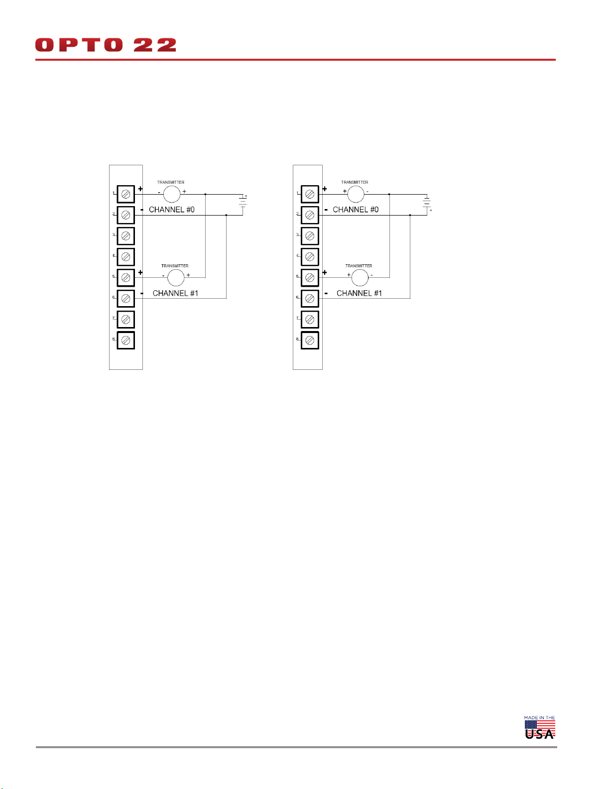
SNAP-AIMA Wiring (Two channels)
SNAP-AIMA-4 Wiring (Four channels)
© 2001–2019 Opto 22. All rights reserved. Dimensions and specifications are subject to change. Brand or product names used herein are trademarks or registered trademarks of their respective companies or organizations.
DATA SHEET
Form 1065-191230
PAGE 8
CURRENT INPUT MODULE, -20 mA TO +20 mA, TWO OR FOUR CHANNELS (CONTINUED)
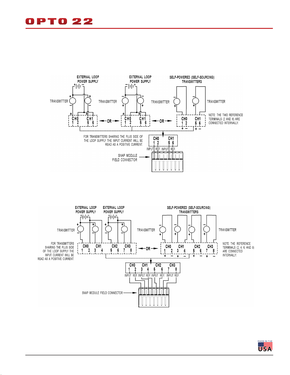
SNAP-AIMA Wiring: Positive Common vs. Negative Common Connections
The following diagrams apply to SNAP-AIMA-2, SNAP-AIMA-4, and SNAP-AIMA-8 modules.
NOTE: Even-numbered terminals share a
common reference where applicable.
SNAP-AIMA
For transmitters sharing the plus side of the loop
supply. Note that input current will be read as a
positive current.
NOTE: Even-numbered terminals share a
common reference where applicable.
SNAP-AIMA
For transmitters sharing the minus side of the loop
supply. Note that input current will be read as a
negative current.
© 2001–2019 Opto 22. All rights reserved. Dimensions and specifications are subject to change. Brand or product names used herein are trademarks or registered trademarks of their respective companies or organizations.
CURRENT INPUT MODULE, -20 mA TO +20 mA, EIGHT CHANNELS
DATA SHEET
Form 1065-191230
PAGE 9
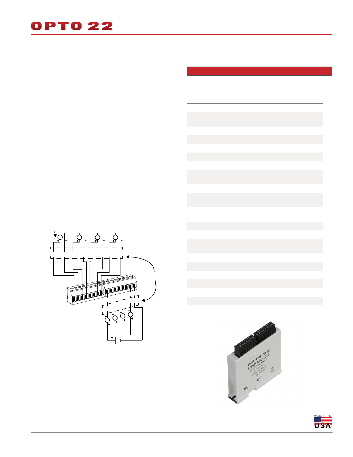
SNAP-AIMA-8
Description
The SNAP-AIMA-8 module provides an input range of -20mA to
+20mA with eight channels of analog current input. (If you need a
similar module with 32 channels, see page 10.) The SNAP-AIMA-8 can
be used with SNAP PAC brains and rack-mounted controllers only.
These modules DO NOT supply loop excitation current.
Since all inputs share a common reference, the module must be
installed at the beginning or end of a typical 4–20mA loop. If you are
using both standard and self-sourcing transmitters, either put the
transmitters on different modules or use different power supplies. If
you need channels that are isolated from each other on the same
module, see Opto 22 form #1182.
If you have multiple self-sourcing transmitters that share the same
positive common, do not use this module. Use the SNAP-AIMA-i
module instead. See Opto 22 form #1182.
Current Source
4-20 self-powered
(self-sourcing) transmitters
T
T TT
23 45 67 8
2
1
NOTE: Terminals 2, 4, 6, and 8 on both
connectors are connected internally.
CH 2CH 1CH 0 CH 3
8
7
6
5
4
3
2
1
3
CH 4
T
8
7
6
5
4
CH 5
T
CH 6
T
CH 7
T
OR
Part Number Description
SNAP-AIMA-8
Eight-channel analog current input, -20 mA to
+20 mA
Specifications
Input Range -20 mA to +20 mA
Over-Range Limits
Resolution 0.8 microamps
Data Freshness (Max) 0.28 seconds
DC Common Mode Rejection >-120 dB
AC Common Mode Rejection >-120 dB @ 60 Hz
Maximum Survivable Input 36 mA or 9 VDC
Maximum Operating Common
Mode Voltage
Accuracy 0.05% (10 microamps)
DRIFT: Gain Temperature
Coefficient
DRIFT: Offset Temperature
Coefficient
Isolation 1500 V
Power Requirements 5 VDC (±0.15 ) @ 170 mA
Input Resistance - Single
Ended
Operating Temperature -20 °C to 70 °C
Storage Temperature -40 °C to 85 °C
Humidity 5-95%, non-condensing
Torque, hold-down screws 4 in-lb (0.45 N-m)
Torque, connector screws 1.7 in-lb (0.19 N-m)
Agency Approvals CE, RoHS, DFARS
Warranty Lifetime
From -22 to +22 mA
(+/-20 mA range)
250 V
30 PPM/ °C
15 PPM/ °C
100 ohms (all channels share
the same reference point)
External loop
power supply
NOTE: For transmitters sharing the plus side of the loop power supply, the
input current will be read as a positive current.
See additional wiring diagrams on page 8.
© 2001–2019 Opto 22. All rights reserved. Dimensions and specifications are subject to change. Brand or product names used herein are trademarks or registered trademarks of their respective companies or organizations.
CURRENT INPUT MODULE, -20 MA TO +20 MA, 32 CHANNELS
DATA SHEET
Form 1065-191230
PAGE 10
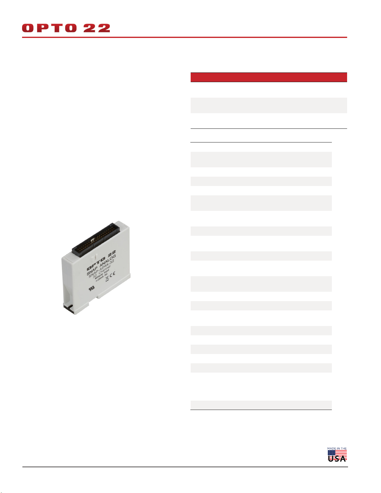
SNAP-AIMA-32 and SNAP-AIMA-32-FM
Description
The SNAP-AIMA-32 and SNAP-AIMA-32-FM modules provide 32
channels of input with an input range of -20mA to +20mA. The
SNAP-AIMA-32-FM is Factory Mutual approved. Check the table on
page 3 for I/O processor compatibility. Dimensional drawings are on
page 45.
These modules DO NOT supply loop excitation current.
Channels are not isolated from each other. Since all inputs share a
common reference, the module must be installed at the beginning or
end of a typical 4–20 mA loop. If you use both standard and
self-sourcing transmitters, put the transmitters on different modules
or use different power supplies. (If you need channels that are isolated
from each other on the same module, see Opto 22 form #1182.)
Part Number Description
SNAP-AIMA-32
SNAP-AIMA-32-FM
SNAP-HD-BF6
SNAP-AIMA-HDB
SNAP-AIMA-HDB-FM
32-channel analog current input,
-20 mA to +20 mA
Wiring harness for SNAP-AIMA-32 modules
and breakout racks
Breakout racks for SNAP-AIMA-32 and
SNAP-AIMA-32-FM
Specifications
Input Range -20 mA to +20 mA
Over-Range Limits
Resolution 0.8 microamps
Input Filtering -3 dB @ 31 Hz
Data Freshness (Max) 1.15 s
DC Common Mode Rejection
AC Common Mode Rejection
Maximum Survivable Input 36 mA or 9 VDC
Maximum Operating Common Mode Voltage
Accuracy 0.1% (20 microamps)
DRIFT: Gain Temperature
Coefficient
DRIFT: Offset Temperature
Coefficient
Isolation 1500 V, field to logic
Power Requirements 5 VDC (±0.15 ) @ 150 mA
Input Resistance - Single
Ended
Operating Temperature -20 °C to 70 °C
Storage Temperature -40 °C to 85 °C
Humidity 5-95%, non-condensing
Torque, hold-down screws 4 in-lb (0.45 N-m)
Torque, connector screws 5.26 in-lb (0.6 N-m)
Agency Approvals
Warranty Lifetime
From -22 to +22 mA
(+/-20 mA range)
>-120 dB
>-120 dB @ 60 Hz
250 V
30 PPM/ °C
15 PPM/ °C
100 ohms (each channel)
SNAP-AIMA-32: UL, CE, RoHS,
DFARS.
SNAP-AIMA-32-FM: CE, FM,
RoHS, DFARS
© 2001–2019 Opto 22. All rights reserved. Dimensions and specifications are subject to change. Brand or product names used herein are trademarks or registered trademarks of their respective companies or organizations.
DATA SHEET
Form 1065-191230
PAGE 11
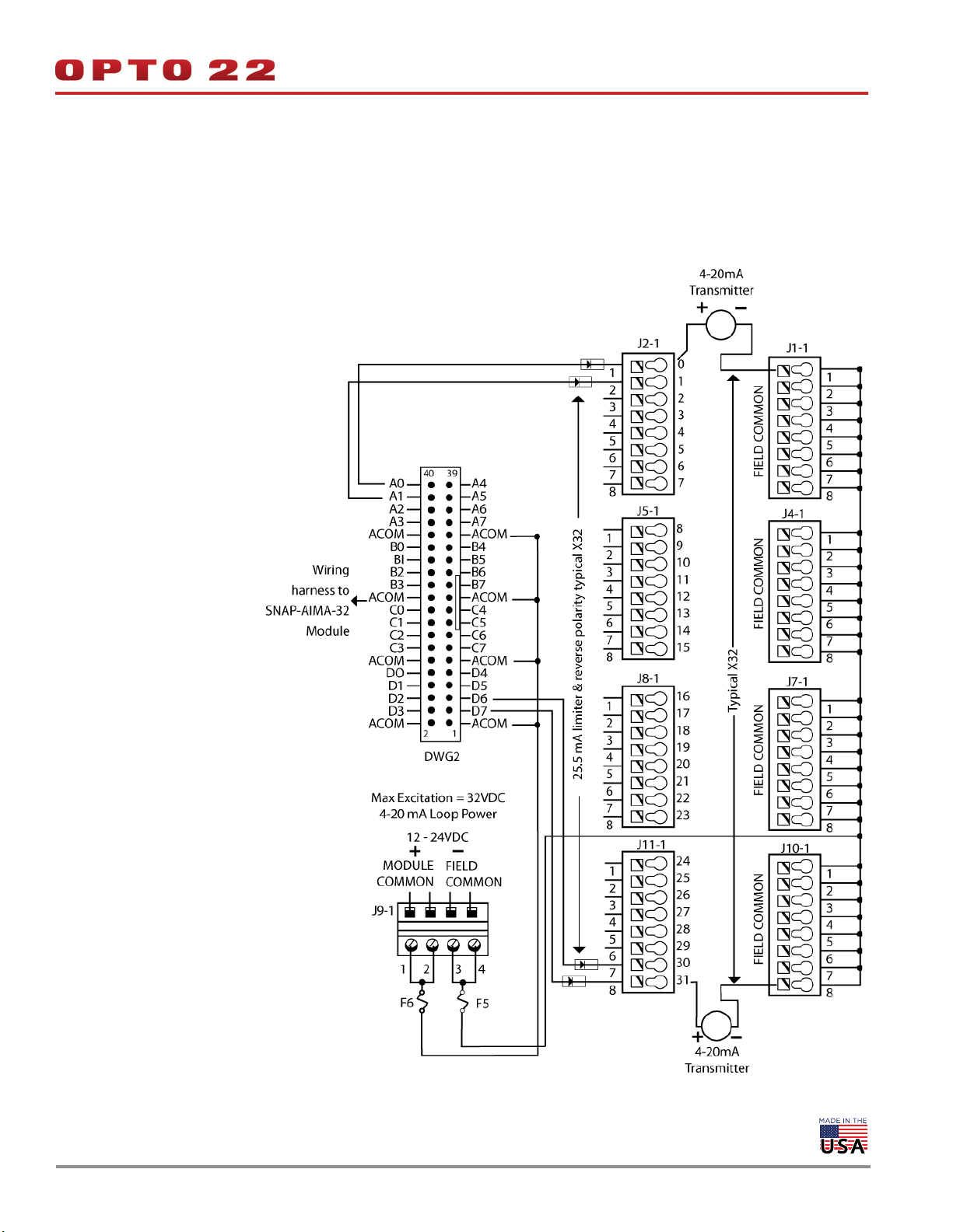
Wiring
SNAP TEX cables and a breakout rack are available separately for
wiring points to field devices (see form #1756, the SNAP TEX Cables &
Breakout Boards Data Sheet). The SNAP-HD-BF6 cable connects the
module to the breakout rack, which can then be wired to field
devices. (NOTE: The SNAP-HD-CBF6 wiring harness with flying leads is
not recommended for this module.)
CAUTION: We strongly recommend that you use the breakout rack
with these modules. Miswiring of any point on the module can cause
severe out-of-warranty damage. The breakout rack protects the
module from many wiring errors.
if you are using the module with loop power (2-wire) negative
common devices, connect to the SNAP-AIMA-HDB (or -FM) rack. If you
are using the module with self-powered devices (4-wire) or with
devices that share a common positive connection, do not use the
SNAP-AIMA-HDB (or -FM) boards, which have a current limiting diode.
Instead, wire to the SNAP-AIV-HDB or SNAP-AIV-HDB-FM.
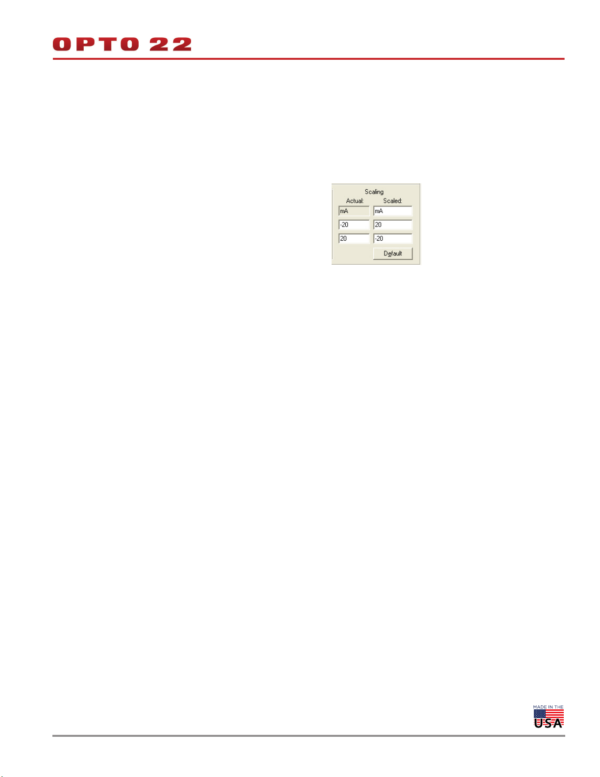
Correcting for Inverted Scaling
Positive readings for these modules appear as negative values.
Therefore, in order to obtain meaningful readings, use the scaling
feature in PAC Control as follows:
1. In the Add or Edit Analog Point dialog box for each point, choose
the scalable version of the module.
2. Under Scaling, scale each point negatively as shown below:
© 2001–2019 Opto 22. All rights reserved. Dimensions and specifications are subject to change. Brand or product names used herein are trademarks or registered trademarks of their respective companies or organizations.
CURRENT INPUT MODULE, -20 mA TO +20 mA, 32 CHANNELS (CONTINUED)
Wiring diagram: SNAP-AIMA-HDB breakout rack to SNAP-AIMA-32 module
NOTE: This diagram also applies to the SNAP-AIMA-HDB-FM rack and the SNAP-AIMA-32-FM module.
Use with loop power (2-wire) negative common devices only.
For self-powered (4-wire) devices, see page 36.
For positive common devices, see page 39.
DATA SHEET
Form 1065-191230
PAGE 12
© 2001–2019 Opto 22. All rights reserved. Dimensions and specifications are subject to change. Brand or product names used herein are trademarks or registered trademarks of their respective companies or organizations.
0 TO 25,000 Hz ANALOG RATE INPUT MODULE
DATA SHEET
Form 1065-191230
PAGE 13
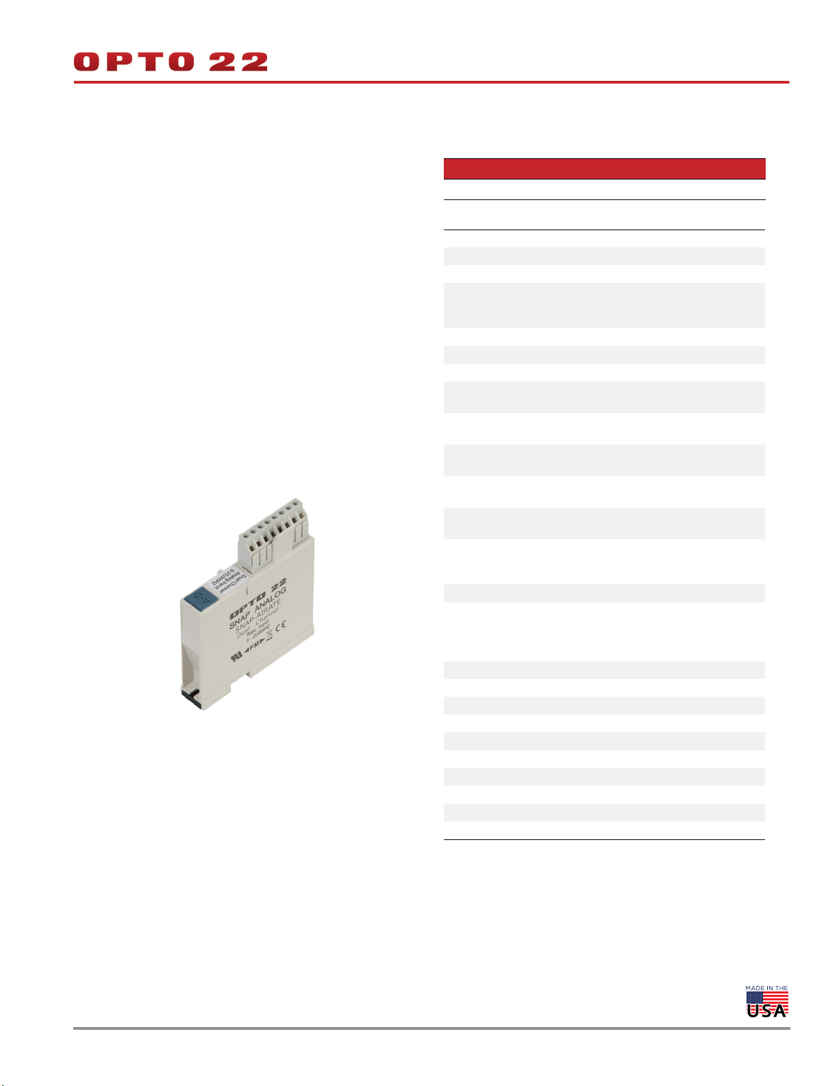
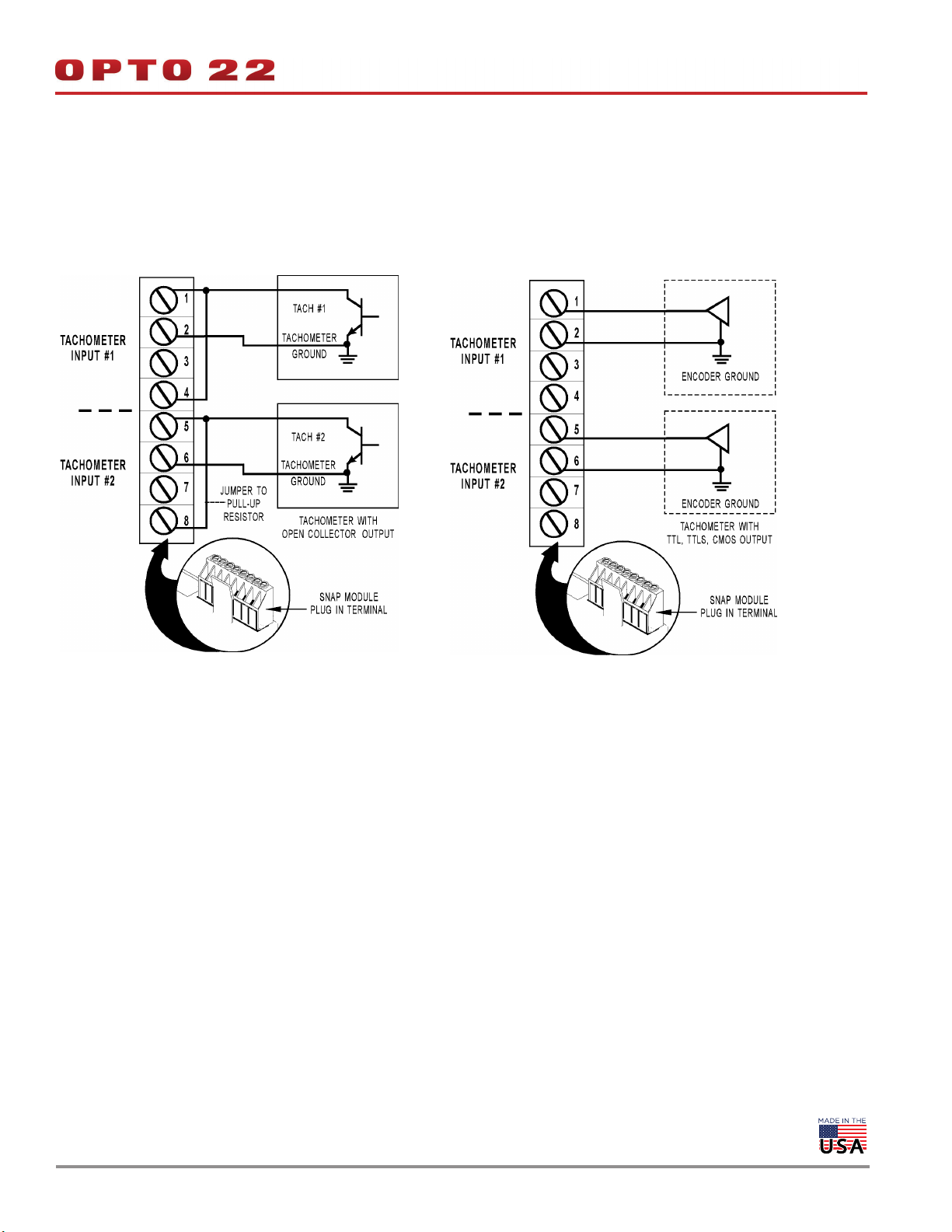
SNAP-AIRATE
Description
The SNAP-AIRATE module provides two channels of
frequency-to-digital conversion. The nominal input range is 0 to
25,000 Hz with an over-range capability to 27,500 Hz. Nine volts
through a 4.7 K ohm pull-up resistor are provided internally for use
with devices that have open collector outputs. This feature eliminates
the need for the user to provide the pull-up voltage supply and
associated wiring, barrier strips, etc.
The module works with TTL, CMOS, and open collector outputs. Truly
a two-wire hookup, the SNAP-AIRATE module is ideally suited for use
with a tachometer.
Please note that this module does not provide channel-to-channel
isolation. If you need isolated channels, see the SNAP Isolated Analog
Input Modules Data Sheet, form 1182.
Number Description
SNAP-AIRATE 0–25,000 Hz analog rate input
Specifications
Nominal Input Range 0 to 25,000 Hz
Input Over-Range To 27,500 Hz
Resolution 1 Hz
Input Response Time(% of
span / delta Hz / delta time)
Data Freshness (Max) 126 ms
DC Common Mode Rejection > -120 dB
AC Common Mode Rejection > -120 dB at 60 Hz
Maximum Operating Common
Mode Voltage
Accuracy (% full scale)
Drift: Gain Temperature Coefficient
Drift: Offset Temperature Coefficient
Input Coupling
Input Amplitude
Sine wave
Square wave
Minimum Pulse Width 18 microseconds
Input Impedance (Inputs share
the same reference point.)
Pull-up Voltage
Pull-up Resistor
Isolation 1500 V
Power Requirements 5 VDC (±0.15 V) at 190 mA
Operating Temperature -20 °C to 70 °C
Storage Temperature -40 °C to 85 °C
Humidity 5-95%, non-condensing
Wire size 22 to 14 AWG
Torque, hold-down screws 4 in-lb (0.45 N-m)
Torque, connector screws 5.26 in-lb (0.6 N-m)
Agency Approvals UL, FM, CE, RoHS, DFARS
Warranty Lifetime
10.0% / 2,500 Hz / 0.1 sec
63.2% / 15.8 K Hz / 0.9 sec
99.0% / 24.75 K Hz / 4.2 sec
250 V
±4 Hz or ±0.5% of the input frequency (whichever is greater)
200 ppm / °C
50 ppm / °C
Single-ended AC (capacitor
coupled)
2.5 V to 24 V p-p
0.5 V to 24 V p-p
50 K ohms AC coupled
(-input to +input)
6 to 9 V
4.7 K ohms
© 2001–2019 Opto 22. All rights reserved. Dimensions and specifications are subject to change. Brand or product names used herein are trademarks or registered trademarks of their respective companies or organizations.
0 TO 25,000 Hz ANALOG RATE INPUT MODULE (CONTINUED)
NAP-AIRATE Wiring Diagrams
DATA SHEET
Form 1065-191230
PAGE 14
NOTE: This module does not provide channel-to-channel isolation.
© 2001–2019 Opto 22. All rights reserved. Dimensions and specifications are subject to change. Brand or product names used herein are trademarks or registered trademarks of their respective companies or organizations.
THERMISTOR INPUT MODULE 0–40 K, 0–20 K, 0–10 K, OR 0–5 K OHM
DATA SHEET
Form 1065-191230
PAGE 15
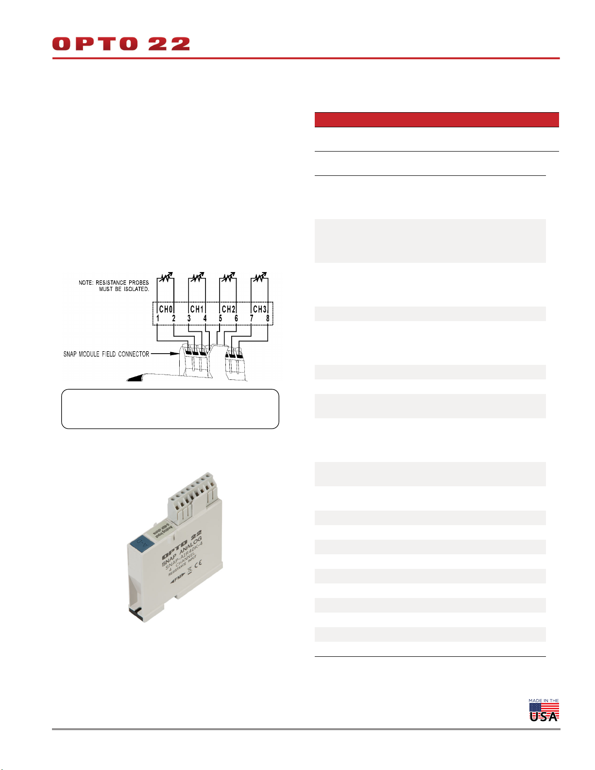
SNAP-AIR40K-4
Description
The SNAP-AIR40K-4 module provides four channels of analog to
digital conversion, ideal for thermistors used in HVAC applications or
for reading the resistance of potentiometer input. See the table on
page 3 for I/O processor compatibility.
The default input range is 0 to 40 K Ohms. The module can also be
configured for 0 to 20 K, 0 to 10 K, or 0 to 5 K Ohms.
NOTE: Resistance probes must be isolated from each other.
IMPORTANT: The mounting rack connector has 24 pins; the module
connector has 20 pins. The extra pins on the mounting rack
connector prevent misalignment of the module during installation.
Part Number Description
SNAP-AIR40K-4
Four-channel analog resistor/thermistor input, 40 K
Ohms, 20 K Ohms, 10 K Ohms, or 5 K Ohms
Specifications
0 to 40,000 Ohms
Input Range
Maximum Over-Range
Resolution
Input Filtering -3 dB @ 3.2 Hz
Data Freshness (Max)
DC Common Mode Rejection >-120 dB
AC Common Mode Rejection >-120 dB @ 60 Hz
Maximum Operating
Common Mode Voltage
Accuracy
DRIFT: Gain Temperature
Coefficient
DRIFT: Offset Temperature
Coefficient
Isolation 1500 V
Power Requirements 5 VDC (±0.15 ) @ 190 mA
Operating Temperature -20 °C to 70 °C
Storage Temperature -40 °C to 85 °C
Humidity 5-95%, non-condensing
Wire size 22 to 14 AWG
Torque, hold-down screws 4 in-lb (0.45 N-m)
Torque, connector screws 5.26 in-lb (0.6 N-m)
Agency Approvals UL, FM, CE, RoHS, DFARS
Warranty Lifetime
0 to 20,000 Ohms
0 to 10,000 Ohms
0 to 5,000 Ohms
44 K (40 K Ohms range)
22 K (20 K Ohms range)
11 K (10 K Ohms range)
5.5 K (5 K Ohms range)
1.6 Ohm @ 40 K Ohms
0.8 Ohm @ 20 K Ohms
0.4 Ohm @ 10 K Ohms
0.2 Ohm @ 5 K Ohms
100 (40 K Ohms)
200 (20 K Ohms)
400 (10 K Ohms)
800 (5 K Ohms)
250 V
0.1% ± 40 Ohms @ 40 K Ohms
0.1% ± 20 Ohms @ 20 K Ohms
0.1% ± 10 Ohms @ 10 K Ohms
0.1% ± 5 Ohms @ 5 K Ohms
30 PPM/ °C
15 PPM/ °C
© 2001–2019 Opto 22. All rights reserved. Dimensions and specifications are subject to change. Brand or product names used herein are trademarks or registered trademarks of their respective companies or organizations.
DATA SHEET
Form 1065-191230
THERMISTOR INPUT MODULE 0–400 K, 0–200 K, 0–100 K, 0–50 K, 0–40 K, 0–20 K,
0–10 K, 0–5 K, 0–4 K, 0–2 K, 0–1 K, 0–500 OHM
PAGE 16
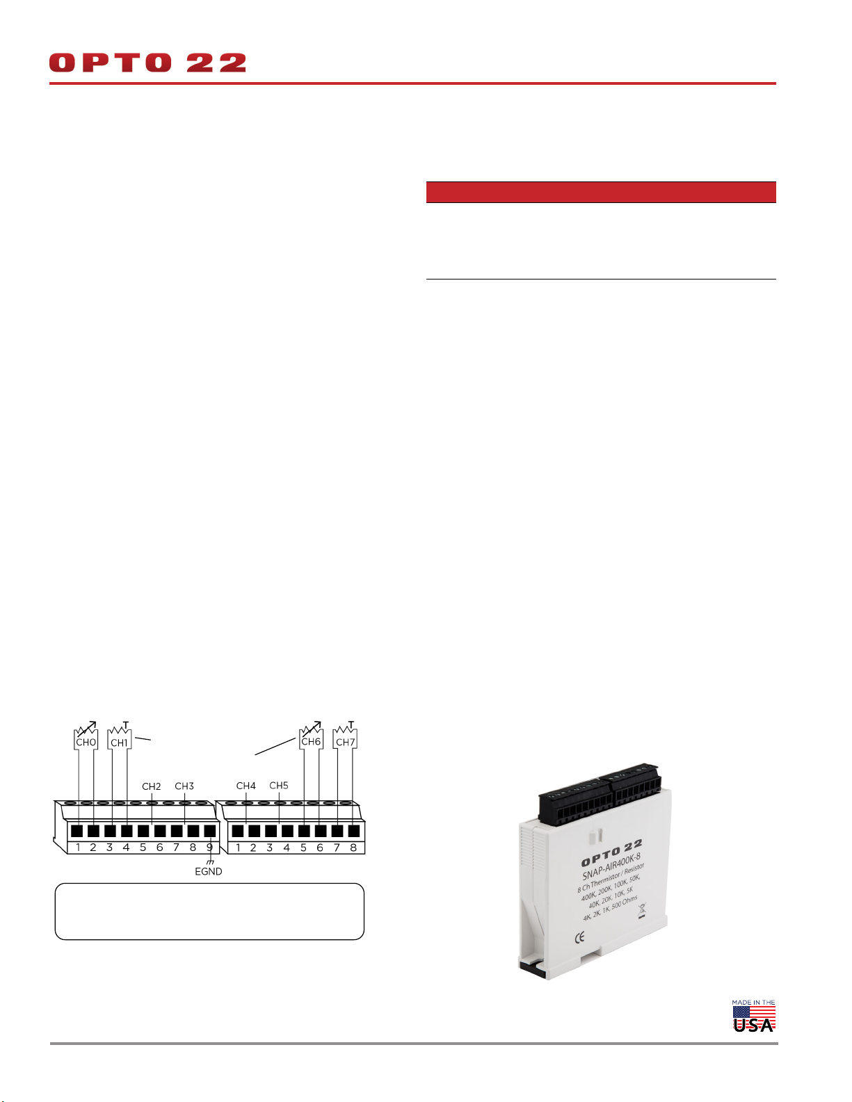
SNAP-AIR400K-8
Description
The SNAP-AIR400K-8 module has eight channels of analog to digital
conversion that convert resistance to temperature or to Ohms. The
module is ideal for NTC thermisters commonly used in HVAC,
refrigeration, and process control applications. It may also be used
with PTC thermisters in resistance sensing applications. See the table
on page 3 for I/O processor compatibility.
The SNAP-AIR400K-8 reads variable resistance type transducers, and it
has 12 resistance input ranges from 500 Ohms to 400 K Ohms, plus
Autorange. Range dependent resolution is from 20 milliOhms to 16
Ohms.
SNAP PAC brains and PAC Control provide direct temperature readings
for four popular thermistors using the Steinhart-Hart equation (see
page 19). You may also enter custom coefficients for other thermistor
curves.
The simple two-wire connections are made to the pluggable terminal
strip on top of the module.
NOTE: The eight input channels must be electrically isolated from each
other and earth ground. The transducer resistor element must be isolated
from any electrically conducting probe tube housing.
Part Number Description
Eight channel analog resistor/thermistor input,
400 K Ohms, 200 K Ohms,
SNAP-AIR400K-8
100 K Ohms, 50 K Ohms, 40 K Ohms,
20 K Ohms, 10 K Ohms, 5 K Ohms,
4 K Ohms, 2 K Ohms, 1 K Ohms, 500 Ohms
Wiring Information
Unshielded 24 AWG wire (minimum) is recommended.
See page 17 for module specifications.
NTC thermistor
Variable resistance device
IMPORTANT: The mounting rack connector has 24 pins; the module
connector has 20 pins. The extra pins on the mounting rack
connector prevent misalignment of the module during installation.
© 2001–2019 Opto 22. All rights reserved. Dimensions and specifications are subject to change. Brand or product names used herein are trademarks or registered trademarks of their respective companies or organizations.

THERMISTOR INPUT MODULE 0–400 K (CONTINUED)
Specifications
DATA SHEET
Form 1065-191230
PAGE 17
Input Ranges
Resolution
Accuracy
(Ohms @ Range)
0.1% Reading
+ 2x Range Resolution
+ 1 Ohm
Data Freshness 1.61 seconds maximum
DSP Notch Filter 20 Hz (- 3DB = 5.24 Hz)
Excitation Current Nominal (Range
& Load Watts Dissipation)
Autorange Step Time
Autorange Ohms Hysteresis
Predefine Curve 2252 curve, 3 K curve, 10 K type 3 curve, 10 K type 2 curve (by Automation Components, Inc.)
DC Common Mode Rejection >-120 dB
AC Common Mode Rejection >-120 dB @ 60 Hz
Open Resistor Indicator Channel resistance = 999,999.999 Ohms
PAC Control Reads temperature reading or -32768 Ohms if over or under range
Maximum Operating Common
Mode Voltage
(Field Term to Logic Connector)
Drift
Gain Tempco
Offset Tempco
Power Requirements 5 VDC (±0.15 ) @ 190 mA
Operating Temperature -20 °C to 70 °C
Storage Temperature -40 °C to 85 °C
Torque, hold-down screws 4 in-lb (0.45 N-m)
Humidity 5-95%, non-condensing
Torque, connector screws 5.26 in-lb (0.6 N-m)
Agency Approvals UL, CE
Warranty Lifetime
• 400 K, 200 K, 100 K, 50 K, 40 K, 20 K, 10 K, 5 K , 4 K, 2 K, 1 K, 500 Ohms, or Autorange
• Predefined or custom curve
Resolution
16 Ohm
8 Ohm
4 Ohm
2 Ohm
400 Ohms @ 400 K
200 Ohms @ 200 K
100 Ohms @ 100 K
0 Ohms @ 50 K
9uA (50 K–4.1 uW), (100 K–8.1 uW), (200 K–16 uW), (400 K–32 uW)
90uA (5 K–40 uW), (10 K–81 uW), (20 K–160 uW), (40 K–320 uW)
200uA (500 K–20 uW), (1 K–40 uW), (2 K–80 uW), (4 K–160 uW)
1.6 seconds to next higher or lower range
>= 10 seconds for a 500 Ohms to 400 K Ohms step change
Ohms Open > 440K
20K between 200K & 400K
10K between 100K & 200K
5K between 50K & 100K
19K between 40K & 50K
2K between 20K & 40K
1K between 10K & 20K
500 between 5K & 10K
500 VDC or peak VAC
30 PPM / °C
15 PPM / °C
Range
0 to 400 kOhms
0 to 200 kOhms
0 to 100 kOhms
0 to 50 kOhms
Ranges
Resolution
1.6 Ohm
0.8 Ohm
0.4 Ohm
0.2 Ohm
40 Ohms @ 40 K
20 Ohms @ 20 K
10 Ohms @ 10 K
5 Ohms @ 5 K
Range
0 to 40 kOhms
0 to 20 kOhms
0 to 10 kOhms
0 to 5 kOhms
Ohms Open > 440K
1.9K between 4K & 5K
200 between 2K & 4K
100 between 1K & 2K
Resolution
0.16 Ohm
0.08 Ohm
0.04 Ohm
0.02 Ohm
4 Ohms @ 4 K
2 Ohms @ 2 K
1 Ohms @ 1 K
0.5 Ohms @ 500
50 between 500 & 1K
Range
0 to 4 kOhms
0 to 2 kOhms
0 to 1 kOhms
0 to 500 Ohms
© 2001–2019 Opto 22. All rights reserved. Dimensions and specifications are subject to change. Brand or product names used herein are trademarks or registered trademarks of their respective companies or organizations.

THERMISTOR INPUT MODULE 0–400 K (CONTINUED)
DATA SHEET
Form 1065-191230
PAGE 18
Predefined Curves
The following table shows temperatures in °C and °F that correlate
with resistance values in Ohms for the generic curve types for four
popular thermistors using the Steinhart-Hart equation. Choose the
curve type for your application in PAC Control or PAC Manager when
you configure a SNAP-AIR400K-8 module. (For custom curves, see
Choose a 2-wire thermistor value with a resistance over the target
temperature range that is much larger than the lead resistance for
your application
Lower value curves (2252 or 3K) work best at cooler temperatures (<
25 °C or 77 °F) because long lead wire resistance can add significant
errors to the measurement.
page 19.)
SNAP-AIR400K-8 Predefined Curves Table
2252 curve 3K curve 10K type 3 curve 10K type 2 curve
Temp °C Temp °F Resistance (Ohms)
-40 -40 75,769.0 100,935.0 239,686.0 336,450.0
-35 -31 54,647.0 72,798.0 179,200.0 242,660.0
-30 -22 39,851.0 53,088.0 135,185.0 176,960.0
-25 -13 29,368.0 39,123.0 102,861.0 130,410.0
-20 -4 21,861.0 29,122.0 78,913.0 97,072.0
-15 5 16,429.0 21,885.0 61,020.0 72,951.0
-10 14 12,459.0 16,598.0 47,543.0 55,326.0
-5 23 9,532.0 12,698.0 37,313.0 42,326.0
0 32 7,353.0 9,795.0 29,490.0 32,650.0
5 41 5,718.0 7,617.0 23,457.0 25,391.0
10 50 4,481.0 5,970.0 18,780.0 19,899.0
15 59 3,538.0 4,713.0 15,130.0 15,711.0
20 68 2,813.0 3,748.0 12,263.0 12,492.0
25 77 2,252.0 3,000.0 10,000.0 10,000.0
30 86 1,814.0 2,417.0 8,194.0 8,057.0
35 95 1,471.0 1,959.0 6,752.0 6,531.0
40 104 1,200.0 1,598.0 5,592.0 5,326.0
45 11 3 983.8 1,311.0 4,655.0 4,368.0
50 122 811.2 1,081.0 3,893.0 3,602.0
55 131 672.5 895.8 3,271.0 2,986.0
60 140 560.3 746.3 2,760.0 2,488.0
65 149 469.0 624.8 2,339.0 2,083.0
70 158 394.5 525.5 1,990.0 1,752.0
75 167 333.1 443.8 1,700.0 1,479.0
80 176 282.7 376.6 1,458.0 1,255.0
85 185 240.9 320.9 1,255.0 1,070.0
90 194 206.2 274.6 1,084.0 915.4
95 203 177.1 236.0 939.3 786.6
© 2001–2019 Opto 22. All rights reserved. Dimensions and specifications are subject to change. Brand or product names used herein are trademarks or registered trademarks of their respective companies or organizations.

2252 curve 3K curve 10K type 3 curve 10K type 2 curve
Temp °C Temp °F Resistance (Ohms)
100 212 152.8 203.6 816.8 678.6
105 221 132.3 176.3 712.6 587.6
110 230 115.0 153.2 623.6 510.6
115 239 100.3 133.6 547.3 445.2
120 248 87.7 116.9 481.8 389.6
125 257 77.0 102.6 425.3 341.9
130 266 67.8 90.3 376.4 301.0
135 275 59.9 79.7 334.0 265.8
140 284 53.0 70.6 297.2 235.4
145 293 47.1 62.7 265.1 209.0
150 302 41.9 55.8 237.0 186.1
The information in this table is provided by Automation Components, Inc.
DATA SHEET
Form 1065-191230
PAGE 19
Custom Curves
To configure the SNAP-AIR400K-8 with custom curves, follow these
steps:
1. Configure the I/O unit in PAC Control, PAC Manager, or EtherNet/IP
Configurator, and save the configuration to flash memory.
2. Open PAC Manager and choose Tools > Inspect.
3. In the Device Name field, enter the I/O unit's IP address. Click the
Point Config button in the left navigation.
4. Choose the module number and point number you want to
configure.
5. Click in the Value column next to Point Type and choose
Temperature from the dropdown menu.
6. Scroll down and click the Value column next to Thermistor Curve.
Choose Unknown.
7. For each coefficient (A, B, K, C), click the Value column and enter
your custom coefficient.
8. Click the Apply button at right.
9. Save the configuration to flash memory: Click the Status Write
button, under Operation highlight Store configuration to flash,
and click Send Command.
© 2001–2019 Opto 22. All rights reserved. Dimensions and specifications are subject to change. Brand or product names used herein are trademarks or registered trademarks of their respective companies or organizations.

RTD INPUT MODULES
DATA SHEET
Form 1065-191230
PAGE 20
SNAP-AIRTD, SNAP-AIRTD-1K, and SNAP-AIRTD-10
Description
The SNAP-AIRTD and SNAP-AIRTD-1K platinum and the
SNAP-AIRTD-10 copper modules are usually used for temperature
inputs. They can also be used to make high-resolution resistance
measurements.
On all three modules, the two inputs share the same reference
terminal. Make sure you use isolated RTD probes.
The SNAP-AIRTD-10 and SNAP-AIRTD-1K require a SNAP PAC brain or
R-series controller.
Also see the SNAP-AIRTD-8U module on page 22.
Part Number Description
SNAP-AIRTD-1K Two-channel 1000 ohm platinum RTD input
SNAP-AIRTD Two-channel 100 ohm platinum RTD input
SNAP-AIRTD-10 Two-channel 10 ohm copper RTD input
Wiring
RTD input modules are designed for three-wire connections, shown
in the diagram below.
If you use a four-wire
connection (shown at
the bottom right), DO
NOT connect the fourth
wire, as it will cause
errors in the readings.
Two-wire connections
are not recommended,
as they will degrade
accuracy and stability.
IMPORTANT: The mounting rack connector has 24 pins; the
module connector has 20 pins. The extra pins on the
mounting rack connector prevent misalignment of the
module during installation.
© 2001–2019 Opto 22. All rights reserved. Dimensions and specifications are subject to change. Brand or product names used herein are trademarks or registered trademarks of their respective companies or organizations.

Form 1065-191230
RTD INPUT MODULES (CONTINUED)
Specifications
SNAP-AIRTD-1K SNAP-AIRTD SNAP-AIRTD-10
1000 ohm platinum @ 0 °C
= 0.00385
3-wire RTD input
1000 ohm nickel @ 0 °C
= 0.00618
1000 ohm nickel @ 70 °F
= 0.00637
Input Temperature Range
Input Range 0 to 4000 ohms 0 to 400 ohms 0 to 25 ohms
Over-Range Limit to 4400 ohms to 440 ohms to 27.5 ohms
Resolution (average) 0.042 °C (0.16 ohms) 0.042 °C (0.016 ohms) 0.026 °C (0.001 ohms)
Input Filtering -3 dB @ 0.1 Hz -3 dB @ 0.1 Hz -3 dB @ 100 Hz
Data Freshness (Max) 100 ms 100 ms 168 ms
Lead Compensation
DC Common Mode Rejection >-120 dB >-120 dB >-120 dB
AC Common Mode Rejection >-120 dB at 60 Hz >-120 dB at 60 Hz >-120 dB at 60 Hz
Excitation (typical) 0.256 mA constant current 1.25 mA constant current 5.4 mA constant current
Maximum Lead Resistance
Maximum Fault Voltage at Input
(between any 2 field wires)
Maximum Operating Common
Mode Voltage
Accuracy
From factory
After setting gain and offset
Isolation 1500 V 1500 V 1500 V
Power Requirements 5.00 to 5.20 VDC @ 190 mA 5.00 to 5.20 VDC @ 190 mA 5.00 to 5.20 VDC @ 190 mA
Operating Temperature -20 °C to 70 °C -20 °C to 70 °C -20 °C to 70 °C
Storage Temperature -40 °C to 85 °C -40 °C to 85 °C -40 °C to 85 °C
Wire size 22 to 14 AWG 22 to 14 AWG 22 to 14 AWG
Humidity 5-95%, non-condensing 5-95%, non-condensing 5-95%, non-condensing
Torque, hold-down screws 4 in-lb (0.45 N-m) 4 in-lb (0.45 N-m) 4 in-lb (0.45 N-m)
Torque, connector screws 5.26 in-lb (0.6 N-m) 5.26 in-lb (0.6 N-m) 5.26 in-lb (0.6 N-m)
Agency Approvals CE, RoHS, DFARS UL, FM, CE, RoHS, DFARS CE, RoHS, DFARS
Warranty Lifetime Lifetime Lifetime
-200 °C to 850 °C
(-328° to +1,582° F)
Automatic when used with
SNAP brains
40 ohms single wire (all leads
to be equal resistance)
±15 V ±15 V ±15 V
250 V 250 V 250 V
0.8 °C
0.6 °C
100 ohm platinum; = 0.00385
100 ohm nickel, -60 to 250 °C
120 ohm nickel, -80 to 260 °C
-200 °C to 850 °C
(-328° to +1,582° F)
Automatic when used with
SNAP brains
40 ohms single wire (all leads to
be equal resistance)
0.8 °C
0.6 °C
10 ohm copper; = 0.00428
-180 °C to 260 °C
(-292° to +500° F)
Automatic when used with
SNAP PAC brains
15 ohms single wire (all leads
to be equal resistance)
0.6 °C
0.5 °C
DATA SHEET
PAGE 21
© 2001–2019 Opto 22. All rights reserved. Dimensions and specifications are subject to change. Brand or product names used herein are trademarks or registered trademarks of their respective companies or organizations.

RTD INPUT MODULES (CONTINUED)
SNAP-AIRTD-8U
Description
The SNAP-AIRTD-8U provides 8 input channels, each individually
software configurable. This module is commonly used for 3-wire RTD
temperature inputs but is
also suited to
high-resolution resistance
measurements. It features
open circuit detection if any
wire breaks.
All 8 inputs share the same
reference terminal. Make
sure you use isolated RTD
probes.
The SNAP-AIRTD-8U
requires a SNAP PAC brain
or R-series controller with
firmware R9.5a or higher. The module cannot be used with legacy
brains or controllers.
Point Configuration
See table at right. You can individually configure each of the module’s
8 points for a variety of behaviors:
• Temperature—Range is fixed. Default range is 0–8000 ohms.
Choose nickel, platinum, or copper RTD input. The data returned
is degrees C or degrees F, depending on your choice for the I/O
unit.
• Fixed-range (default)—Choose the range you want to use. If the
value goes above the limit for that range, an out-of-range value
(16-bit) of –32768 is displayed. The data returned is resistance in
ohms.
• Full Auto-range—The module scrolls up and down the entire
set of ranges and dynamically chooses the appropriate range for
best resolution. Note that this point type can result in higher
latency when ranging up (see Specifications on next page). The
data returned is resistance in ohms.
• Auto-range Down—The module scrolls down and up within the
specified range limit. If the value goes above the specified range,
an out-of-range value (16-bit) of –32768 is displayed. These point
types allow auto-ranging within the selected range but limit the
data latency when ranging up. The data returned is resistance in
ohms.
DATA SHEET
Form 1065-191230
PAGE 22
Part Number Description
SNAP-AIRTD-8U
8-channel multifunction 3-wire RTD/resistance input
Point Configuration (continued)
Point configuration choices for each of the 8 inputs (default is
highlighted in gray):
Point Type Range*
1k Ohm at 70 °F Ni -46 to +148.9 °C
1k Ohm at 0 °C Ni -40 to +135 °C
1k Ohm Pt -200 to +850 °C
120 Ohm Ni -80 to +260 °C
100 Ohm Ni -60 to +250 °C
100 Ohm Pt -200 to +850 °C
10 Ohm Cu -60 to +355 °C
Fixed-range (Default) 0 - 8000 Ohms
Fixed-range 0 - 4000 Ohms
Fixed-range 0 - 2000 Ohms
Fixed-range 0 - 1000 Ohms
Fixed-range 0 - 800 Ohms
Fixed-range 0 - 400 Ohms
Fixed-range 0 - 200 Ohms
Fixed-range 0 - 100 Ohms
Fixed-range 0 - 80 Ohms
Fixed-range 0 - 40 Ohms
Fixed-range 0 - 20 Ohms
Fixed-range 0 - 10 Ohms
Full Auto-range 0 - 8000 Ohms
Auto-range Down 0 - 4000 Ohms
Auto-range Down 0 - 2000 Ohms
Auto-range Down 0 - 1000 Ohms
Auto-range Down 0 - 800 Ohms
Auto-range Down 0 - 400 Ohms
Auto-range Down 0 - 200 Ohms
Auto-range Down 0 - 100 Ohms
Auto-range Down 0 - 80 Ohms
Auto-range Down 0 - 40 Ohms
Auto-range Down 0 - 20 Ohms
Auto-range Down 0 - 10 Ohms
* Maximum range; actual range depends on your probe.
© 2001–2019 Opto 22. All rights reserved. Dimensions and specifications are subject to change. Brand or product names used herein are trademarks or registered trademarks of their respective companies or organizations.

RTD INPUT MODULES (CONTINUED)
Wiring
The SNAP-AIRTD-8U has a plug-in terminal on top with spring-clamp
connectors for easy wiring. An insertion tool is provided in the box
with the module.
For each connection:
1. Insert the tool in the small square hole and push down.
2. Push the wire firmly into the rectangular hole below the tool, and
then remove the tool.
The module is designed for 3-wire RTDs, shown below. All wires must
be the same size. If you use a 4-wire connection, DO NOT connect the
fourth wire, as it will cause errors in the readings. If you use 2-wire
RTDs (not recommended because measurement is less accurate), you
must jumper terminal 2 to 3 for each applicable RTD channel.
DATA SHEET
Form 1065-191230
PAGE 23
A Note on Calibration
Because the SNAP-AIRTD-8U uses intermittent excitation current for
measurements, it cannot be used with RTD calibrators that require a
steady excitation current.
Insert tool here and push down.
Insert wire here and remove tool.
IMPORTANT: The mounting rack connector has 24 pins; the
module connector has 20 pins. The extra pins on the
mounting rack connector prevent misalignment of the
module during installation.
© 2001–2019 Opto 22. All rights reserved. Dimensions and specifications are subject to change. Brand or product names used herein are trademarks or registered trademarks of their respective companies or organizations.

RTD INPUT MODULES (CONTINUED)
Specifications
SNAP-AIRTD-8U
1000 ohm platinum @ 0 °C
= 0.00385
Range: -200 to 850 °C
(-328 to 1,582 °F)
3-wire RTD input and maximum temperature
table range (actual range depends on your
probe)
1000 ohm nickel @ 0 °C
= 0.00618
Range: -60 to 170 °C
(-76 to 356 °F)
1000 ohm nickel @ 70 °F
= 0.00637
Range: -46 to 148.9 °C
(-50 to 300 °F)
Input Range 0 to 4000 ohms 0 to 400 ohms 0 to 40 ohms
Accuracy
From factory
After setting gain and offset
Excitation Current 0.325 mA 2 mA 4.28 mA
Over-Range Limit 10% overrange for all measurements in ohms
Resolution
In Ohms
In RTD Temperature
Input Filtering
Front end filtering
DSP Notch filter
Data Freshness (Max) 1.2 s
Auto-range Settle Time
Step change from 10 to 8000
Step change from 8000 to 10
Total Lead Resistance 200 ohms maximum
DC Common Mode Rejection >-120 dB
AC Common Mode Rejection >-120 dB at 60 Hz
Maximum Survivable Fault Voltage at Input
(between any 2 field wires)
Maximum Operating Common Mode Voltage 250 V field terminal to logic connector
Isolation 1500 V field side to logic side
Power Requirements 5.00 to 5.20 VDC @ 135 mA
Operating Temperature -20 °C to 70 °C
Storage Temperature -40 °C to 85 °C
Humidity 5-95%, non-condensing
Maximum wire size 20 AWG
Torque, hold-down screws 4 in-lb (0.45 N-m)
Agency Approvals UL, CE, RoHS, DFARS
Warranty Lifetime
0.8 °C (Pt); 0.6 °C (Ni)
0.6 °C (Pt); 0.4 °C (Ni)
The greater of: (Ohms Range / 100,000) or 1 milliohm
<= 10 s ranging up (channel may show overrange until settled)
<= 10 s ranging down (channel will give a reading while settling)
100 ohm platinum @ 0 °C
= 0.00385
Range: -200 °C to 850 °C
(-328 to 1,582 °F)
100 ohm nickel @ 0 °C
= 0.00618
Range: -60 to 250 °C
(-76 to 482 °F)
120 ohm nickel @ 0 °C
10 ohm copper @ 25 °C
= 0.00427
Range: -60 to 355 °C
(-76 to 671 °F)
= 0.00672
Range: -80 to 260 °C
(-112 to 500 °F)
0.8 °C (Pt); 0.6 °C (Ni)
0.6 °C (Pt); 0.4 °C (Ni)
Better than or equal to 0.05 °C (0.09 °F)
-15 dB @ 50 Hz, -20 dB @ 60 Hz
20 Hz (-3 DdB = 5.24 Hz)
1.2 s to the next higher or lower range
±8 V
1.7 °C
1.2 °C
DATA SHEET
Form 1065-191230
PAGE 24
© 2001–2019 Opto 22. All rights reserved. Dimensions and specifications are subject to change. Brand or product names used herein are trademarks or registered trademarks of their respective companies or organizations.

ICTD TEMPERATURE INPUT MODULE, TWO OR FOUR CHANNELS
DATA SHEET
Form 1065-191230
PAGE 25
SNAP-AICTD and SNAP-AICTD-4
Description
SNAP-AICTD and SNAP-AICTD-4 modules provide temperature input
data from any industry-standard Integrated Circuit Temperature
Device (ICTD). The SNAP-AICTD has two channels, and the
SNAP-AICTD-4 has four channels. See the table on page 3 for I/O
processor compatibility.
The simple two-wire connections are made to the pluggable terminal
strip on top of the module. Up to 2,000 feet of ordinary hook-up wire
is used to connect the sensor to the input terminal strip.
Both modules are compatible with all industry-standard ICTD probes,
including the AD-590 family from Analog Devices and Opto 22’s part
number ICTD.
Part Number Description
SNAP-AICTD Two-channel analog temperature input, ICTD
SNAP-AICTD-4 Four-channel analog temperature input, ICTD
Specifications
Input Range with ICTD Probe -40 °C to +100 °C
Module Input Range
Zero Scale
Full Scale
Resolution 0.017 °C
Accuracy with ICTD Probe ±0.8 °C
Sensitivity 1.0 microamps/ °C
Data Freshness (Max)
DC Common Mode Rejection >-120 dB
AC Common Mode Rejection >-120 dB @ 60 Hz
Maximum Operating Common
Mode Voltage
Isolation 1500 V
Power Requirements 5 VDC (± .015 ) @ 150 mA
Operating Temperature -20 °C to 70 °C
Storage Temperature -40 °C to 85 °C
Humidity 5-95%, non-condensing
Wire size 22 to 14 AWG
Torque, hold-down screws 4 in-lb (0.45 N-m)
Torque, connector screws 5.26 in-lb (0.6 N-m)
Agency Approvals UL, FM, CE, RoHS, DFARS
Warranty Lifetime
-273 °C
+150 °C
167 ms (2-channel module)
355 ms (4-channel module)
250 V
© 2001–2019 Opto 22. All rights reserved. Dimensions and specifications are subject to change. Brand or product names used herein are trademarks or registered trademarks of their respective companies or organizations.

ICTD TEMPERATURE INPUT MODULE (CONTINUED)
SNAP-AICTD (Two channels)
IMPORTANT: The mounting rack connector has 24 pins; the
module connector has 20 pins. The extra pins on the
mounting rack connector prevent misalignment of the
module during installation.
DATA SHEET
Form 1065-191230
PAGE 26
SNAP-AICTD-4 (Four channels)
IMPORTANT: The mounting rack connector has 24 pins; the
module connector has 20 pins. The extra pins on the
mounting rack connector prevent misalignment of the
module during installation.
© 2001–2019 Opto 22. All rights reserved. Dimensions and specifications are subject to change. Brand or product names used herein are trademarks or registered trademarks of their respective companies or organizations.

ICTD TEMPERATURE INPUT MODULE, EIGHT CHANNELS
DATA SHEET
Form 1065-191230
PAGE 27
SNAP-AICTD-8
Description
The SNAP-AICTD-8 module provides temperature input data from any
industry-standard Integrated Circuit Temperature Device (ICTD). It has
eight channels of input. The SNAP-AICTD-8 can be used only with
SNAP PAC brains and rack-mounted controllers (standard wired and
Wired+Wireless models).
The simple two-wire connections are made to the terminal strip on
top of the module. Up to 2,000 feet of ordinary hook-up wire is used
to connect the sensor to the input terminal strip.
The module is compatible with all industry-standard ICTD probes,
including the AD-590 family from Analog Devices and Opto 22’s part
number ICTD.
ICTD Source
WHT
WHT
WHT
WHT
BLK
12345678
BLK
4
3
2
1
BLK
CH 2CH 1CH 0 CH 3
1
8
7
6
5
BLK
8
7
6
5
4
3
2
Part Number Description
SNAP-AICTD-8 Eight-channel analog temperature input, ICTD
Specifications
Input Range with ICTD Probe -40 °C to +100 °C
Module Input Range
Zero Scale
Full Scale
Data Freshness (Max) 0.28 seconds
Resolution 0.017 °C
Accuracy with ICTD Probe ±0.8 °C
Sensitivity 1.0 mA/ °C
DC Common Mode Rejection >-120 dB
AC Common Mode Rejection >-120 dB @ 60 Hz
Maximum Operating Common
Mode Voltage
Isolation 1500 V
Power Requirements 5 VDC (± .015 ) @ 170 mA
Operating Temperature -20 °C to 70 °C
Storage Temperature -40 °C to 85 °C
Humidity 5-95%, non-condensing
Torque, hold-down screws 4 in-lb (0.45 N-m)
Torque, connector screws 1.7 in-lb (0.19 N-m)
Agency Approvals CE, RoHS, DFARS
Warranty Lifetime
-273 °C
+150 °C
250 V
12345678
WHT
BLK
WHT
CH 6CH 5CH 4 CH 7
WHT
BLK
BLK
WHT
BLK
NOTE: Terminals 2, 4, 6, and 8 on both
connectors are connected internally.
© 2001–2019 Opto 22. All rights reserved. Dimensions and specifications are subject to change. Brand or product names used herein are trademarks or registered trademarks of their respective companies or organizations.

THERMOCOUPLE/MILLIVOLT INPUT MODULE
DATA SHEET
Form 1065-191230
PAGE 28
SNAP-AITM
Description
The SNAP-AITM module provides two channels of analog to digital
conversion. Each channel on the module can be configured for
-150 mV DC to +150 mV DC or -75 mV DC to +75 mV DC, or for
type E, J, or K thermocouple operation.
Since both inputs share the same reference terminal, use isolated
probes for thermocouple inputs. If you need isolated channels on
the same module, see Opto 22 form #1182.
Thermocouple Polarity and Range
Type – + Range
E Red Purple -270°C to +1,000 °C
J Red White -210°C to +1,200 °C
K Red Yellow -270°C to +1,372 °C
IMPORTANT: The mounting rack connector has 24 pins; the
module connector has 20 pins. The extra pins on the
mounting rack connector prevent misalignment of the
module during installation.
Part Number Description
Two-channel analog type E, J, or K thermocouple
SNAP-AITM
or -150 mV to +150 mV input or -75 mV to +75 mV
input
Specifications
Input Range
Over-Range Limits
Resolution
Cold Junction Temperature
Compensation
Input Filtering -3 dB @ 7 Hz
Input Response Time
(% of span/delta V/delta time)
Data Freshness (Max)
DC Common Mode Rejection >-120 dB
AC Common Mode Rejection >-120 dB @ 60 Hz
Maximum Survivable Input ±15 volts
Maximum Operating Common Mode Voltage
Accuracy at Full Scale
Drift: Gain Temperature
Coefficient
Drift: Offset Temperature
Coefficient
Thermocouple Accuracy [°C]
From factory
After user gain and offset
commands
Isolation 1500 V
Power Requirements 5 VDC (±0.15) @ 170 mA
Input Resistance 100 Megohms (each channel)
Ambient Temperature:
Operating
Storage
Humidity 5-95%, non-condensing
Torque, hold-down screws 4 in-lb (0.45 N-m)
Torque, connector screws 3 in-lb (0.34 N-m)
Agency Approvals FM, CE, RoHS, DFARS
Warranty Lifetime
-150 mV to +150 mV
-75 mV to +75 mV
-165 to +165 mV (+/-150 mV range)
-82.5 to +82.5 mV (+/-75 mV range)
6 microvolts from -150 to +150 mV
3 microvolts from -75 to +75 mV
Automatic when used with
SNAP I/O processors
63.2%/95 mV/23 mS
167 ms (+/-150 mV)
334 ms (+/-75 mV)
250 V
0.06% (90 microvolts) @ 150 mV
0.1% (75 microvolts) @ 75 mV
5 microvolts / °C
2 microvolts / °C
± 2.0 (E, J, and K)
± 0.8
-20 °C to 70 °C
-40 °C to 85 °C
© 2001–2019 Opto 22. All rights reserved. Dimensions and specifications are subject to change. Brand or product names used herein are trademarks or registered trademarks of their respective companies or organizations.

THERMOCOUPLE/MILLIVOLT INPUT MODULE
DATA SHEET
Form 1065-191230
PAGE 29
SNAP-AITM-2
Description
The SNAP-AITM-2 module provides an input range of ±50 mV, ±25
mV, or Type B, C, D, G, N, T, R, or S thermocouple.
Since both inputs share the same reference terminal, use isolated
probes for thermocouple inputs. If you need isolated channels on
the same module, see Opto 22 form #1182.
Thermocouple Polarity and Range
Type – + Range
B RED GRAY +42° C to +1,820 °C
C, D, G RED WHITE 0° C to +2,320 °C
N RED ORANGE -270° C to +1,300 °C
R, S RED BLACK -50° C to +1,768 °C
T RED BLUE -270° C to +400 °C
IMPORTANT: The mounting rack connector has 24 pins; the
module connector has 20 pins. The extra pins on the
mounting rack connector prevent misalignment of the
module during installation.
Part Number Description
Two-channel analog type B, C, D, G, N, T, R, or S ther-
SNAP-AITM-2
mocouple or -50 mV to +50 mVDC input
or -25 mV to +25 mVDC input
Specifications
Input Range
Over-range Limits
Resolution
Cold Junction Temperature
Compensation
Input Filtering -3 dB @ 2.4 Hz
Input Response Time
(% of span/delta V/delta time)
Data Freshness (Max)
DC Common Mode Rejection >-120 dB
AC Common Mode Rejection >-120 dB @ 60 Hz
Maximum Survivable Input ±15 volts
Maximum Operating
Common Mode Voltage
Accuracy at Full Scale
Drift: Gain Temperature
Coefficient
Drift: Offset Temperature
Coefficient
Thermocouple Accuracy [°C] B, R, S C, D, G T, N
From factory ±5 ±4 ±3
After user gain and offset
commands
Isolation 1500 V
Power Requirements 5 VDC (±0.15 ) @ 170 mA
Input Resistance 100 Megohms (each channel)
Ambient Temperature:
Operating
Storage
Humidity 5-95%, non-condensing
Agency Approvals FM, CE, RoHS, DFARS
Torque, hold-down screws 4 in-lb (0.45 N-m)
Torque, connector screws 3 in-lb (0.34 N-m)
Warranty Lifetime
-50 mV to +50 mVDC
-25 mV to +25 mVDC
-55 to +55 mV (+/-50 mV range)
-27.5 to +27.5 mV (+/-25 mV range)
2 microvolts from -50 mV to +50 mV
1 microvolts from -25 mV to +25 mV
Automatic when used with
SNAP brains
63.2%/31.5 mV/66 ms
167 ms (+/- 50 mV)
334 ms (+/- 25 mV)
250 V
0.1% (50 microvolts) @ 50 mV
0.2% (50 microvolts) @ 25 mV
5 microvolts / °C
2 microvolts / °C
±3 ±2 ±2
-20 °C to 70 °C
-40 °C to 85 °C
© 2001–2019 Opto 22. All rights reserved. Dimensions and specifications are subject to change. Brand or product names used herein are trademarks or registered trademarks of their respective companies or organizations.

THERMOCOUPLE/MILLIVOLT INPUT MODULE
DATA SHEET
Form 1065-191230
PAGE 30
SNAP-AITM-8 and SNAP-AITM-8-FM
Description
The SNAP-AITM-8 and SNAP-AITM-8-FM modules provide
eight channels of analog to digital conversion. Each channel
on the module can be configured for -75 mV DC to +75 mV
DC, -50 mV DC to +50 mV DC, -25 mV DC to +25 mV DC, or
for type B, C, D, E, G, J, K, N, R, S or T thermocouple operation.
Since all inputs share the same reference terminal, use
isolated probes for thermocouple inputs. See the
dimensional diagram on page 42.
Thermocouple Polarity and Range
Type – + Range
B RED GRAY +42° C to +1,820 °C
C, D, G RED WHITE 0° C to +2,320 °C
E RED PURPLE -270°C to +1,000 °C
J RED WHITE -210°C to +1,200 °C
K RED YELLOW -270°C to +1,372 °C
N RED ORANGE -270° C to +1,300 °C
R, S RED BLACK -50° C to +1,768 °C
T RED BLUE -270° C to +400 °C
Millivolt Thermocouple Source
–
–
– +
–
+
0
C
–
+
+
1
+
3
2
C
+
–
–
+
5
4
C
–
Common terminals are connected internally.
NOTE: For best accuracy, wire all points before
calibrating, and short all unused channels.
The SNAP-AITM-8-FM is Factory Mutual approved.
+
7
6
C
Part Number Description
SNAP-AITM-8
SNAP-AITM-8-FM
8-channel B, C, D, E, G, J, K, N, R, S, or T thermocouple
or -75 mV to +75 mV, 50 mV to +50 mV, or 25 mV to
+25 mV input
Specifications
-75 mV to +75 mV
Input Range
Over-Range Limits
Resolution
Cold Junction Temperature
Compensation
Input Filtering -3 dB @ 5 Hz
Data Freshness (Max) 2.25 s
DC Common Mode Rejection >-120 dB
AC Common Mode Rejection >-120 dB @ 60 Hz
Maximum Survivable Input ±15 volts
Max Operating Common Mode
Voltage
Accuracy at Full Scale
Drift: Gain Temperature Coefficient 5 microvolts / °C
Drift: Offset Temperature Coefficient
Thermocouple Accuracy [°C] E, J, K B, R, S C, D, G T, N
From factory ±2.0 ±5 ±4 ±3
After user gain and offset commands
Isolation 1500 V
Power Requirements 5 VDC (±0.15) @ 200 mA
Input Resistance 100 Megohms (each channel)
Ambient Temperature:
Operating
Storage
Humidity 5-95%, non-condensing
Torque, hold-down screws 4 in-lb (0.45 N-m)
Torque, connector screws 3 in-lb (0.34 N-m)
Agency Approvals
Warranty Lifetime
-50 mV to +50 mV
-25 mV to +25 mV
-82.5 to +82.5 mV (+/-75 mV range)
-55 to +55 mV (+/-50 mV range)
-27.5 to +27.5 mV (+/-25 mV range)
3 microvolts from -75 mV to +75 mV
2 microvolts from -50 mV to +50 mV
1 microvolts from -25 mV to +25 mV
Automatic when used with SNAP I/O
processors
250 V
0.1% (75 microvolts) @ 75 mV
0.1% (50 microvolts) @ 50 mV
0.2% (50 microvolts) @ 25 mV
2 microvolts / °C
±0.5 ±3 ±2 ±2
-20 °C to 70 °C
-40 °C to 85 °C
SNAP-AITM-8: UL, CE, RoHS, DFARS
SNAP-AITM-8-FM: FM, CE, RoHS, DFARS
© 2001–2019 Opto 22. All rights reserved. Dimensions and specifications are subject to change. Brand or product names used herein are trademarks or registered trademarks of their respective companies or organizations.

0 TO 250 VOLT RMS AC/DC INPUT MODULE
SNAP-AIVRMS
Description
The SNAP-AIVRMS module provides an input range of 0 to 250 volts
AC or DC. The SNAP-AIVRMS module may be used to monitor
120/240-volt AC/DC and 12/24/48-volt AC/DC system voltage.
Terminals 3, 4, 7, and 8 share a common connection inside the
module. Make sure you observe polarity when connecting the second
channel. To avoid a potentially hazardous short, double-check wiring
before turning on the voltage to be monitored.
If you need a module with channel-to-channel isolation, see form
#1182, the SNAP Isolated Analog Input Modules Data Sheet.
DATA SHEET
Form 1065-191230
Part Number Description
SNAP-AIVRMS Two-channel 0 to 250 V RMS AC/DC input
Specifications
Input Range 0 to 250 V RMS AC/DC
Input Over-Range To 275 V
Input Resistance 1 M ohms
Accuracy ±0.2 V and ±0.2% reading
Resolution 10 mV
DC Reversal ± 0.4 V (.16%)
Input Response Time
(Step Change)
Data Freshness (Max) 32.3 ms
DC Common Mode Rejection >-120 dB
AC Common Mode Rejection >-120 dB @ 60 Hz
Maximum Operating
Common Mode Voltage
Isolation 1500 V
Power Requirements 5 VDC (±0.15 V) at 170 mA
Operating Temperature -20 °C to 70 °C
Storage Temperature -40 °C to 85 °C
Humidity 5-95%, non-condensing
Wire size 22 to 14 AWG
Torque, hold-down screws 4 in-lb (0.45 N-m)
Torque, connector screws 5.26 in-lb (0.6 N-m)
Agency Approvals UL, FM, CE, RoHS, DFARS
Warranty Lifetime
5% (12.5 V) in 100 mS
63.2% (158 V) in 200 mS
99% (248 V) in 1200 mS
250 V
PAGE 31
© 2001–2019 Opto 22. All rights reserved. Dimensions and specifications are subject to change. Brand or product names used herein are trademarks or registered trademarks of their respective companies or organizations.

DATA SHEET
Form 1065-191230
PAGE 32
VOLTAGE INPUT MODULE, -10 VDC TO +10
VDC OR -5 VDC TO +5 VDC,
TWO OR FOUR CHANNELS
SNAP-AIV and SNAP-AIV-4
Description
The SNAP-AIV and SNAP-AIV-4 modules can be configured for either
-10 VDC to +10 VDC or -5 VDC to +5 VDC operation on each channel.
The SNAP-AIV provides two channels, and the SNAP-AIV-4 four. If you
need a module with more channels, see page 34. See the table on
page 3 for I/O processor compatibility.
Note that all channels share a common reference terminal. If you need
two isolated channels on the same module, see Opto22 form #1182.
Part Number Description
SNAP-AIV Two-channel analog voltage input -10 to +10 VDC
SNAP-AIV-4 Four-channel analog voltage input -10 to +10 VDC
Specifications
Input Range
Over-Range Limits
Resolution
Input Filtering -3 dB @ 64 Hz
Input Response Time
(% of span/ delta V / delta t)
Data Freshness (Max)
DC Common Mode
Rejection
AC Common Mode
Rejection
Maximum Survivable Input 220 VAC or 300 VDC
Maximum Operating
Common Mode Voltage
Accuracy
Gain Temperature
Coefficient
Offset Temperature
Coefficient
Isolation 1500 V
Power Requirements 5 VDC (±0.15) @ 170 mA
Input Resistance
Ambient Temperature:
Operating
Storage
Humidity 5-95%, non-condensing
Wire size 22 to 14 AWG
Torque, hold-down screws 4 in-lb (0.45 N-m)
Torque, connector screws 5.26 in-lb (0.6 N-m)
Agency Approvals UL, FM, CE, RoHS, DFARS
Warranty Lifetime
From -10 volts to +10 volts
From -5 volts to +5 volts
From -11 to +11 volts (+/-10 V range)
From -5.5 to +5.5 volts (+/-5 V range)
0.4 mV when configured -10 to +10 volts
0.2 mV when configured -5 to +5 volts
63.2% / 6.7 V / 10 ms
11.5 ms (2-channel, +/- 10 VDC)
23 ms (2-channel, +/- 5 VDC
23 ms (4-channel, +/- 10 VDC)
46 ms (4-channel, +/- 5 VDC
>-120 dB
>-120 dB @ 60 Hz
250 V
0.05%, 5 mV @ 10 VDC
2.5 mV @ 5 VDC
30 PPM/ °C
15 PPM/ °C
1 M ohms (each channel; both channels
share the same reference point)
-20 °C to 70 °C
-40 °C to 85 °C
© 2001–2019 Opto 22. All rights reserved. Dimensions and specifications are subject to change. Brand or product names used herein are trademarks or registered trademarks of their respective companies or organizations.

VOLTAGE INPUT MODULE, -10 VDC TO +10 VDC OR -5 VDC TO +5 VDC,
FOUR CHANNELS (CONTINUED)
SNAP-AIV (Two channels)
IMPORTANT: The mounting rack connector has 24 pins; the module
connector has 20 pins. The extra pins on the mounting rack
connector prevent misalignment of the module during installation.
DATA SHEET
Form 1065-191230
PAGE 33
SNAP-AIV-4 (Four channels)
© 2001–2019 Opto 22. All rights reserved. Dimensions and specifications are subject to change. Brand or product names used herein are trademarks or registered trademarks of their respective companies or organizations.

DATA SHEET
Form 1065-191230
PAGE 34
VOLTAGE INPUT MODULE, -10 VDC TO +10 VDC OR -5 VDC TO +5 VDC, EIGHT CHANNELS
SNAP-AIV-8
Part Number Description
Description
The SNAP-AIV-8 module can be configured for either -10 VDC to +10
VDC or -5 VDC to +5 VDC operation on each of its eight input
channels. (If you need a module with more channels, see page 35.)
The SNAP-AIV-8 can be used only with SNAP PAC brains and
rack-mounted controllers (standard wired and Wired+Wireless
models).
Note that all channels share a common reference terminal. If you need
two isolated channels on the same module, see Opto22 form #1182.
Voltage Source
CH 2CH 1CH 0 CH 3
8
7
6
5
4
3
2
1
8
7
6
5
4
3
2
1
CH 6CH 5CH 4 CH 7
NOTE: Terminals 2, 4, 6, and 8 on both
connectors are connected internally.
SNAP-AIV-8 Eight-channel analog voltage input -10 to +10 VDC
Specifications
Input Range
Over-Range Limits
Resolution
Input Filtering -3 dB @ 64 Hz
Data Freshness (Max) 0.28 seconds
DC Common Mode Rejection >-120 dB
AC Common Mode
Rejection
Maximum Survivable Input 220 VAC or 300 VDC
Maximum Operating Common Mode Voltage
Accuracy
Gain Temperature
Coefficient
Offset Temperature Coefficient
Isolation 1500 V
Power Requirements 5 VDC (±0.15) @ 170 mA
Input Resistance
Ambient Temperature:
Operating
Storage
Humidity 5-95%, non-condensing
Torque, hold-down screws 4 in-lb (0.45 N-m)
Torque, connector screws 1.7 in-lb (0.19 N-m)
Agency Approvals CE, RoHS, DFARS
Warranty Lifetime
-10 volts to +10 volts
-5 volts to +5 volts
-11 to +11 volts (+/-10 V range)
-5.5 to +5.5 volts (+/-5 V range)
0.4 mV when configured -10 to +10 V
0.2 mV when configured -5 to +5 V
>-120 dB @ 60 Hz
250 V
0.05%, 5 mV @ 10 VDC
2.5 mV @ 5 VDC
30 PPM/ °C
15 PPM/ °C
1 M ohms (all channels share the
same reference point)
-20 °C to 70 °C
-40 °C to 85 °C
© 2001–2019 Opto 22. All rights reserved. Dimensions and specifications are subject to change. Brand or product names used herein are trademarks or registered trademarks of their respective companies or organizations.

VOLTAGE INPUT MODULE, -10 VDC TO +10 VDC OR -5 VDC TO +5 VDC,
32 CHANNELS
DATA SHEET
Form 1065-191230
PAGE 35
SNAP-AIV-32 and SNAP-AIV-32-FM
Specifications
Input Range
Over-Range Limits
Resolution
Input Filtering -3 dB @ 31 Hz
Data Freshness (Max) 1.1 s
DC Common Mode Rejection >-120 dB
AC Common Mode Rejection >-120 dB @ 60 Hz
Maximum Survivable Input 220 VAC or 300 VDC
Maximum Operating Common
Mode Voltage
Accuracy
Gain Temperature
Coefficient
Offset Temperature Coefficient 15 PPM/ °C
Isolation 1500 V
Power Requirements 5 VDC (±0.15) @ 150 mA
Input Resistance
Ambient Temperature:
Operating
Storage
Humidity 5-95%, non-condensing
Torque, hold-down screws 4 in-lb (0.45 N-m)
Torque, connector screws 5.26 in-lb (0.6 N-m)
Agency Approvals
Warranty Lifetime
-10 volts to +10 volts
-5 volts to +5 volts
-11 to +11 volts (+/-10 V range)
-5.5 to +5.5 volts (+/-5 V range)
0.4 mV when configured -10
volts to +10 volts
0.2 mV when configured -5
volts to +5 volts
250 V
0.05%, 5 mV @ 10 VDC
2.5 mV @ 5 VDC
30 PPM/ °C
1 M ohms (each channel; all
channels share the same reference point)
-20 °C to 70 °C
-40 °C to 85 °C
SNAP-AIV-32: UL, CE, RoHS,
DFARS
SNAP-AIV-32-FM: FM, CE,
RoHS, DFARS
Part Number Description
SNAP-AIV-32
SNAP-AIV-32-FM
SNAP-HD-CBF6
SNAP-HD-BF6
SNAP-AIV-HDB
SNAP-AIV-HDB-FM
32-channel analog voltage input -10 to +10 VDC
Wiring harness with flying leads for
SNAP-AIV-32 modules
Wiring harness for SNAP-AIV-32 modules and
SNAP-AIV-HDB breakout racks
Breakout racks for SNAP-AIV-32 and
SNAP-AIV-32-FM
Description
The SNAP-AIV-32 and SNAP-AIV-32-FM modules can be configured
for either -10 VDC to +10 VDC or -5 VDC to +5 VDC operation on each
of its 32 channels. See the table on page 3 for I/O processor
compatibility. The SNAP-AIV-32-FM is Factory Mutual approved.
Note that all channels share a common reference terminal. (For
channel-to-channel isolated modules, see Opto22 form #1182.)
SNAP TEX cables and a breakout rack are available separately for
wiring points to field devices (see form #1756, the SNAP TEX Cables &
Breakout Boards Data Sheet). The SNAP-HD-BF6 wiring harness
connects the module to the breakout rack, which can then be wired
to field devices. The SNAP-HD-CFB6 wiring harness has flying leads to
connect to field devices.
See the dimensional drawing for the module on page 45.
© 2001–2019 Opto 22. All rights reserved. Dimensions and specifications are subject to change. Brand or product names used herein are trademarks or registered trademarks of their respective companies or organizations.

DATA SHEET
Form 1065-191230
VOLTAGE INPUT MODULE -10 VDC TO +10 VDC OR -5 VDC TO +5 VDC (CONTINUED)
Wiring diagram: SNAP-AIV-HDB breakout rack to SNAP-AIV-32 or SNAP-AIV-32-FM module
NOTE: This diagram is also used to wire the SNAP-AIV-HDB breakout rack to a SNAP-AIMA-32 or SNAP-AIMA-32-FM
module, when the module connects to self-powered (4-wire) device.
PAGE 36
© 2001–2019 Opto 22. All rights reserved. Dimensions and specifications are subject to change. Brand or product names used herein are trademarks or registered trademarks of their respective companies or organizations.

MILLIVOLT INPUT MODULE
SNAP-AIMV2-4
Description
The SNAP-AIMV2-4 module provides four channels of analog to digital
conversion. See the table on page 3 for I/O processor compatibility.
Each channel on the module can be configured for -50 mV DC to +50
mV DC or -25 mV DC to +25 mV DC.
Note that all inputs share the same reference terminal.
IMPORTANT: The mounting rack connector has 24 pins; the
module connector has 20 pins. The extra pins on the
mounting rack connector prevent misalignment of the
module during installation.
Form 1065-191230
Part Number Description
SNAP-AIMV2-4
Four-channel -50 to +50 mV input or -25 mV to
+25 mV input
Specifications
Input Range
Over-Range Limits
Resolution
Input Filtering -3 dB @ 2.4Hz
Input Response Time
(% of span/delta V/delta time)
Data Freshness (Max)
DC Common Mode Rejection >-120 dB
AC Common Mode Rejection >-120 dB @ 60 Hz
Maximum Survivable Input ±15 volts
Maximum Operating Common Mode Voltage
Accuracy at Full Scale
Drift: Gain Temperature Coefficient
Drift: Offset Temperature
Coefficient
Isolation 1500 V
Power Requirements 5 VDC (±0.15 ) @ 170 mA
Input Resistance - Single
Ended
Operating Temperature -20 °C to 70 °C
Storage Temperature -40 °C to 85 °C
Humidity 5-95%, non-condensing
Wire size 22 to 14 AWG
Torque, hold-down screws 4 in-lb (0.45 N-m)
Torque, connector screws 5.26 in-lb (0.6 N-m)
Agency Approvals UL, FM, CE, RoHS, DFARS
Warranty Lifetime
From -50 mV to +50 mV
From -25 mV to +25m V
From -55 to +55 mV
(+/-50 mV range)
From -27.5 to +27.5 mV
(+/-25 mV range)
2 microvolts (-50 mV to +50 mV)
1 microvolt (-25 mV to +25 m V)
63.2%/31.5 mV/66 ms
335 ms (+/- 50 mV)
668 ms (+/- 25 mV)
250 V
0.1% (50 microvolts) @ 50m V
0.2% (50 microvolts) @ 25 mV
3 microvolts / °C
2 microvolts / °C
100 Megohms (each channel)
DATA SHEET
PAGE 37
© 2001–2019 Opto 22. All rights reserved. Dimensions and specifications are subject to change. Brand or product names used herein are trademarks or registered trademarks of their respective companies or organizations.

MILLIVOLT INPUT MODULE
DATA SHEET
Form 1065-191230
PAGE 38
SNAP-AIMV-4
Description
The SNAP-AIMV-4 module provides four channels of analog to digital
conversion. See the table on page 3 for I/O processor compatibility.
Each channel on the module can be configured for -150 mV DC to
+150 mV DC or -75 mV DC to +75 mV DC.
Note that all inputs share the same reference terminal.
IMPORTANT: The mounting rack connector has 24 pins; the
module connector has 20 pins. The extra pins on the
mounting rack connector prevent misalignment of the
module during installation.
Part Number Description
SNAP-AIMV-4
Four-channel -150 to +150 mV or -75 to
+75 mV input
Specifications
Input Range
Over-Range Limits
Resolution
Input Filtering -3 dB @ 7 Hz
Input Response Time (% of
span/delta V/delta time)
Data Freshness (Max)
DC Common Mode Rejection
AC Common Mode
Rejection
Maximum Survivable Input ±15 volts
Maximum Operating
Common Mode Voltage
Accuracy at Full Scale
Drift: Gain Temperature
Coefficient
Drift: Offset Temperature
Coefficient
Isolation 1500 V
Power Requirements 5 VDC (±0.15 ) @ 170 mA
Input Resistance - Single
Ended
Operating Temperature -20 °C to 70 °C
Storage Temperature -40 °C to 85 °C
Humidity 5-95%, non-condensing
Wire size 22 to 14 AWG
Torque, hold-down screws 4 in-lb (0.45 N-m)
Torque, connector screws 5.26 in-lb (0.6 N-m)
Agency Approvals UL, FM, CE, RoHS, DFARS
Warranty Lifetime
From -150 mV to +150 mV
From -75 mV to +75m V
From -165 to +165 mV
(+/-150 mV range)
From -82.5 to +82.5 mV
(+/-75 mV range)
6 microvolts (-150 mV to +150 mV)
3 microvolts (-75 mV to +75 mV)
63.2%/95 mV/23 ms
335 ms (+/- 150 mV)
668 ms (+/- 75 mV)
>-120 dB
>-120 dB @ 60 Hz
250 V
0.06% (90 microvolts) @ 150 mV
0.1% (75 microvolts) @ 75 mV
3 microvolts / °C
2 microvolts / °C
100 Megohms (each channel)
© 2001–2019 Opto 22. All rights reserved. Dimensions and specifications are subject to change. Brand or product names used herein are trademarks or registered trademarks of their respective companies or organizations.

Alternate Wiring Diagram
SNAP-AIV-HDB breakout rack to SNAP-AIMA-32 or SNAP-AIMA-32-FM module
Use this diagram when the module connects to devices that share a positive common connection
DATA SHEET
Form 1065-191230
PAGE 39
© 2001–2019 Opto 22. All rights reserved. Dimensions and specifications are subject to change. Brand or product names used herein are trademarks or registered trademarks of their respective companies or organizations.

DIMENSIONAL DRAWING
All Two- and Four-channel Modules, except SNAP-AITM-2
DATA SHEET
Form 1065-191230
PAGE 40
© 2001–2019 Opto 22. All rights reserved. Dimensions and specifications are subject to change. Brand or product names used herein are trademarks or registered trademarks of their respective companies or organizations.

DIMENSIONAL DRAWING
SNAP-AITM-2 Modules
DATA SHEET
Form 1065-191230
PAGE 41
© 2001–2019 Opto 22. All rights reserved. Dimensions and specifications are subject to change. Brand or product names used herein are trademarks or registered trademarks of their respective companies or organizations.

DIMENSIONAL DRAWING
SNAP-AITM-8 and SNAP-AITM-8-FM Modules
DATA SHEET
Form 1065-191230
PAGE 42
© 2001–2019 Opto 22. All rights reserved. Dimensions and specifications are subject to change. Brand or product names used herein are trademarks or registered trademarks of their respective companies or organizations.

DIMENSIONAL DRAWING
SNAP-AICTD-8, SNAP-AIMA-8, SNAP-AIV-8, and SNAP-AIR400K-8 Modules
DATA SHEET
Form 1065-191230
PAGE 43
© 2001–2019 Opto 22. All rights reserved. Dimensions and specifications are subject to change. Brand or product names used herein are trademarks or registered trademarks of their respective companies or organizations.

DIMENSIONAL DRAWING
SNAP-AIRTD-8U
3.271 in
[83.1 mm]
DATA SHEET
Form 1065-191230
PAGE 44
3.295 in
[83.7 mm]
.787 in
[20.0 mm]
.730 in
[18.5 mm]
© 2001–2019 Opto 22. All rights reserved. Dimensions and specifications are subject to change. Brand or product names used herein are trademarks or registered trademarks of their respective companies or organizations.

DIMENSIONAL DRAWING
All 32-Channel Modules
DATA SHEET
Form 1065-191230
PAGE 45
© 2001–2019 Opto 22. All rights reserved. Dimensions and specifications are subject to change. Brand or product names used herein are trademarks or registered trademarks of their respective companies or organizations.

DIMENSIONAL DRAWING
All Modules
DATA SHEET
Form 1065-191230
PAGE 46
IMPORTANT: The mounting rack connector has 24 pins; the
module connector has 20 pins. The extra pins on the
mounting rack connector prevent misalignment of the
module during installation.
© 2001–2019 Opto 22. All rights reserved. Dimensions and specifications are subject to change. Brand or product names used herein are trademarks or registered trademarks of their respective companies or organizations.

DIMENSIONAL DRAWING
Height on Rack: All Two- and Four-channel Modules, except SNAP-AITM-2
DATA SHEET
Form 1065-191230
PAGE 47
© 2001–2019 Opto 22. All rights reserved. Dimensions and specifications are subject to change. Brand or product names used herein are trademarks or registered trademarks of their respective companies or organizations.

DIMENSIONAL DRAWING
Height on Rack: 32-Channel Modules
DATA SHEET
Form 1065-191230
PAGE 48
© 2001–2019 Opto 22. All rights reserved. Dimensions and specifications are subject to change. Brand or product names used herein are trademarks or registered trademarks of their respective companies or organizations.

DIMENSIONAL DRAWINGE
Height on Rack: SNAP-AITM-2 Module
DATA SHEET
Form 1065-191230
PAGE 49
© 2001–2019 Opto 22. All rights reserved. Dimensions and specifications are subject to change. Brand or product names used herein are trademarks or registered trademarks of their respective companies or organizations.

DIMENSIONAL DRAWING
Height on Rack: SNAP-AITM-8 and SNAP-AITM-8-FM Modules
DATA SHEET
Form 1065-191230
PAGE 50
© 2001–2019 Opto 22. All rights reserved. Dimensions and specifications are subject to change. Brand or product names used herein are trademarks or registered trademarks of their respective companies or organizations.

DIMENSIONAL DRAWING
Height on Rack: SNAP-AICTD-8, SNAP-AIMA-8, and SNAP-AIV-8
DATA SHEET
Form 1065-191230
PAGE 51
© 2001–2019 Opto 22. All rights reserved. Dimensions and specifications are subject to change. Brand or product names used herein are trademarks or registered trademarks of their respective companies or organizations.

More about Opto 22
PRODUCTS
Opto 22 develops and manufactures reliable, easy-to-use, open
standards-based hardware and software products.
Industrial automation, process control, building automation, industrial
refrigeration, remote monitoring, data acquisition, and industrial
internet of things (IIoT) applications worldwide all rely on Opto 22.
groov EPIC® System
Opto 22’s groov Edge Programmable Industrial Controller (EPIC)
system is the culmination of over 40 years of experience in designing
products for the automation industry.
groov EPIC gives you an industrially hardened system with
guaranteed-for-life I/O, a flexible Linux®-based processor with
gateway functions, and software that meets the needs of your
automation and IIoT applications.
groov EPIC I/O
I/O provides the local connection to
sensors and equipment. groov I/O
offers up to 24 channels on each I/O
module, with a spring-clamp
terminal strip, integrated wireway,
swing-away cover, and LEDs
indicating module health and
digital channel status.
groov I/O is hot swappable, UL
Hazardous Locations approved, and
ATEX compliant. Opto 22 I/O is so
reliable, we guarantee it for life.
• Optional access to the Linux operating system through a secure
shell (SSH) to download and run custom applications
• groov View for building your own device-independent HMI,
viewable on the touchscreen, PCs, and mobile devices.
• Node-RED for creating simple logic flows from pre-built nodes
• Ignition Edge® from Inductive Automation®, with OPC-UA drivers
to Allen-Bradley®, Siemens®, and other control systems, and
MQTT/Sparkplug communications for efficient IIoT data transfer
Older products
From solid state relays (our first products) to world-famous G4 and
SNAP I/O, to SNAP PAC controllers, older Opto 22 products are still
supported and still doing the job at thousands of installations
worldwide. You can count on us to give you the reliability and service
you expect, now and in the future.
QUALITY
Founded in 1974, Opto 22 has
established a worldwide reputation
for high-quality products. All are
made in the U.S.A. at our
manufacturing facility in Temecula,
California.
Because we test each product twice
before it leaves our factory rather than
testing a sample of each batch, we
can afford to guarantee most solidstate relays and optically isolated I/O
modules for life.
groov EPIC Processor
The heart of the system is the groov EPIC processor. It handles a wide
range of digital, analog, and serial functions for data collection,
remote monitoring, process control, and discrete and hybrid
manufacturing.
In addition, the EPIC provides secure data communications among
physical assets, control systems, software applications, online services,
and more, both on premises and in the cloud.
Configuring and troubleshooting I/O and networking is easier with
the EPIC’s integrated high-resolution color touchscreen. Authorized
users can manage the system locally on the touchscreen or on a
monitor connected via the HDMI or USB ports.
groov EPIC Software
Software included in the groov EPIC controller:
• PAC Control engine to run PAC Control strategies and PAC Display
projects
• CODESYS Runtime engine to run IEC61131-3 compliant programs
built with CODESYS Development System
© 2001–2019 Opto 22. All rights reserved. Dimensions and specifications are subject to change. Brand or product names used herein are trademarks or registered trademarks of their respective companies or organizations.
Form 1335-190917
 Loading...