

DIGITAL I/O CARRIER BOARD FOR
RASPBERRY PI
Features
Provides a GPIO interface between a Raspberry Pi®
>
I/O modules on select Opto 22 mounting racks
Perfect for prototyping, proofs of concept, and environments
>
in which an industrially hardened controller isn’t required
Auxiliary 40-pin connector supports HAT add-on boards using
>
UART, SPI, or I
Includes interface cable, Pi board mounting standoffs, and
>
2
C
spare fuses for mounting racks
Code samples available at developer.opto22.com
>
DESCRIPTION
Imagine safely and reliably sensing and switching 5-60 VDC, 120 VAC,
and 240 VAC loads with a Raspberry Pi. Well, now you can!
With Opto 22's Digital I/O Carrier Board for Raspberry Pi,
your Pi can harness the power and performance of world-class,
industrially hardened digital input/output (I/O) modules. Use your Pi
to switch industrial-level electrical loads far beyond the Pi's built in 3.3
VDC GPIO pins, and monitor and control electrical loads required for
real-world devices like industrial motors, pumps, and sensors.
The Carrier Board works with any model Pi with a 40-pin header
connector. Just insert the board’s interface cable into your Pi's GPIO
connector, and snap the board onto a compatible Opto 22 rack.
Use the rack's power supply to power the Pi, and then use your
favorite Pi-supported programming language to read and write to up
to 16 digital I/O points. (Mounting rack, power supply, and I/O
modules are sold separately.)
and digital
DATA SHEET
Form 2199-200302
PAGE 1
OPTO-P1-40P
OPTO-P1-40P
Also, the Carrier Board’s auxiliary 40-pin GPIO connector lets other
Pi-compatible peripherals access the Pi’s unused pins.
Specifications
Interface connectors
Raspberry Pi: Two 40-pin GPIO header connectors
I/O rack: One 50-conductor header connector
Operating temperature -20 to 70 °C
Storage Temperature -40 to 85 °C
Relative Humidity 95%, non-condensing
Agency Approvals CE, RoHS, DFARS
Warranty 30 months from date of manufacture
Part Number
Part Description
OPTO-P1-40P Digital I/O Carrier Board for Raspberry Pi
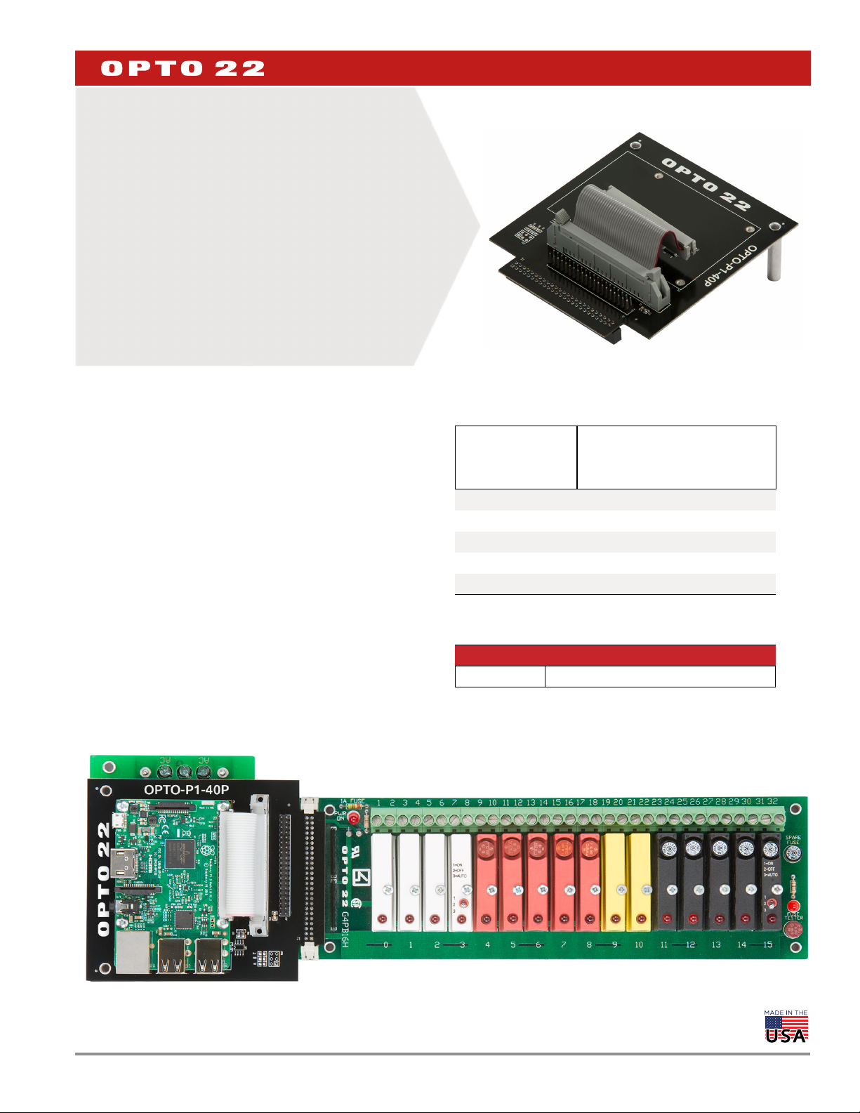
Digital I/O Carrier Board for Raspberry Pi
Shown with Raspberry Pi, G4 I/O modules, mounting rack, and power supply
(all sold separately).
Raspberry Pi® is a trademark of the Raspberry Pi Foundation.
© 2016–2020 Opto 22. All rights reserved. Dimensions and specifications are subject to change. Brand or product names used herein are trademarks or registered trademarks of their respective companies or organizations.
DATA SHEET
Form 2199-200302
PAGE 2
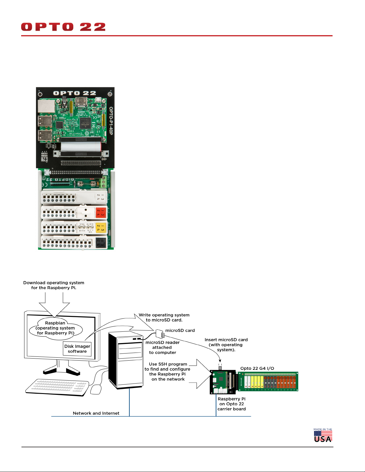
Digital I/O Carrier Board for Raspberry Pi
Shown with Raspberry Pi, SNAP I/O modules, and mounting rack (all
sold separately).
HERE’S WHAT YOU NEED
Raspberry Pi (any model with a 40-pin GPIO header connector,
including Raspberry Pi Models A+ and B+, Pi 2 Model B, Pi 3
Model B, and Pi Zero)
Digital I/O Carrier Board for Raspberry Pi
I/O mounting rack
I/O modules
Power supply
G4 or SNAP?
If you don’t already have I/O for your project, base your choice on the
sensors and actuators you plan to use.
Opto 22 G4 I/O has 1 point per module. Input modules are used
to sense field signals. Each output module is individually fused
and can switch up to 3 A.
(For G4 I/O see page 3.)
Opto 22 SNAP I/O takes up less space with 4 points per module
and costs less per point. Most output modules can switch up to
0.75 A per point or a total of 3 A per module. SNAP-OMR6
modules can switch up to 6 A.
(For SNAP I/O, see page 4.)
If you prefer to use Quad Pak or G1 I/O digital modules, the Carrier
Board also supports the PB16HQ, PB4H, PB8H and PB16H racks.
Physical Setup
Opto 22 I/O has been field-proven for nearly 40 years and is available
worldwide. Most I/O modules carry Opto 22’s Limited Lifetime
Warranty. For details, see
© 2016–2020 Opto 22. All rights reserved. Dimensions and specifications are subject to change. Brand or product names used herein are trademarks or registered trademarks of their respective companies or organizations.

G4 I/O MOUNTING RACKS
These racks can accommodate up to 10 AWG wire. The logic supply is
fused with a 1 A fuse.
DATA SHEET
Form 2199-200302
PAGE 3
power supply to ensure sufficient, consistent, and reliable power to all
devices connected to the Pi.
G4 Power Supplies Input Voltage Output Current
G4 Mounting Racks
G4PB16H Holds 16 I/O modules
G4PB8H Holds 8 I/O modules
G4 I/O MODULES
G4 I/O modules have a built-in LED status indicator to display the
point’s on/off status.
NOTE: 15 and 24 VDC logic modules are not supported.
G4 Inputs
Model Field Voltage Special Features
G4IAC5 90–140 VAC/VDC
G4IAC5A 180–280 VAC/VDC
G4IAC5L 90–140 VAC/VDC
G4IAC5MA 90–140 VAC/VDC Diagnostic switch
G4IDC5
G4IDC5D 2.5–28 VDC Low voltage input
G4IDC5G 35–60 VDC/VAC
G4IDC5MA
G4SWIN NA Simulates input
10–32 VDC
12–32 VAC
10–32 VDC
12–32 VAC
Low input resistance
Diagnostic switch
PBSC 12/24 VDC 1.5 A
Powering Peripherals
If your Pi uses USB-powered peripherals (like hard drives or WiFi
dongles), you’ll need a power supply that puts out more current:
Connect a 5 V power supply rated 2.5 A to 5 A to the G4 rack’s
power terminals.
Replace the G4 rack’s standard 1 A fuse with the 5 A fuse
FUSE05B
—10 pack) included with the Carrier Board.
(part
Mapping: GPIO Pins to G4 Modules
G4 Outputs
Model Field Voltage Special Features
G4OAC5 12–140 VAC @ 3 A
G4OAC5A 24–280 VAC @ 3 A
G4OAC5A5 24–280 VAC @ 3 A Normally closed
G4OAC5MA 12–140 VAC @ 3 A Diagnostic switch
G4OAC5AMA 24–280 VAC @ 3 A Diagnostic switch
G4ODC5 5–60 VDC @ 3 A
G4ODC5A 5–200 VDC @ 3 A
G4ODC5MA 5–60 VDC Diagnostic switch
G4SWOUT NA Simulates output
G4 POWER SUPPLIES
Although it’s possible to power the rack and I/O modules from the Pi,
Opto 22 recommends powering the components from the rack’s
© 2016–2020 Opto 22. All rights reserved. Dimensions and specifications are subject to change. Brand or product names used herein are trademarks or registered trademarks of their respective companies or organizations.

SNAP I/O Mounting Rack
If you’ve decided to use SNAP I/O modules in your Pi project, the
Carrier Board works with the SNAP-D4M mounting rack. The
SNAP-D4M holds 4 SNAP I/O modules (a total of 16 points).
The rack ships with a 1 A fuse. If you are using USB peripherals, replace
it with a 4 A fuse. For convenience, one is included with the
OPTO-P1-40P Carrier Board.
SNAP I/O MODULES
SNAP I/O modules have four points, and each point has an LED to
indicate its status.
SNAP Inputs
Model Field Voltage Special Features
SNAP-IAC5
SNAP-IAC5A
SNAP-IAC5MA
SNAP-IDC5
SNAP-IDC5D
SNAP-IDC5G
SNAP-IDC5-HT
SNAP-IDC5MA
SNAP-IDC5-SW
SNAP-IDC5-SW-NC
90–140 VAC/VDC
180–280 VAC/VDC
120 VAC/VDC
24 VAC/VDC
5 VDC
48 VAC/VDC
24 VAC/VDC
24 VAC/VDC
15 VDC
15 VDC
4 isolated channels,
manual/auto switches
Leakage-tolerant
4 isolated channels,
manual/auto switches
Dry contact,
normally open
Dry contact,
normally closed
DATA SHEET
Form 2199-200302
PAGE 4
SNAP Outputs (Continued)
Model Field Voltage Special Features
Mechanical Power
SNAP-OMR6T-C
5–30 VDC
0–250 VAC
Relay, Form C, with integrated transient suppression
Powering a Pi and SNAP I/O
When using the SNAP-D4M with your Pi and SNAP I/O, attach a
5 VDC @ 200 mA (max.) power supply to the rack. Powering the
components from the rack’s power supply ensures sufficient,
consistent, and reliable power to all devices connected to the Pi.
Mapping: GPIO Pins to SNAP I/O Modules
SNAP Outputs
Model Field Voltage Special Features
SNAP-OAC5
SNAP-OAC5-I
SNAP-OAC5MA
SNAP-ODC5SRC
SNAP-ODC5SNK
SNAP-ODC5ASNK
SNAP-ODC5MA
SNAP-ODC5-I
SNAP-ODC5A-I
SNAP-OMR6-C
12–250 VAC
12–250 VAC
12–250 VAC
5–60 VDC
5–60 VDC
5–200 VDC
5–60 VDC
5–60 VDC
5–200 VDC
5–30 VDC
0–250 VAC
4 isolated channels
4 isolated channels,
manual/auto switches
Load sourcing
Load sinking
Load sinking
4 isolated channels,
manual/auto switches
4 isolated channels
4 isolated channels
Mechanical Power
Relay, Form C
Read and Write with Pi
It’s easy to read and write to Opto 22 I/O points using your favorite
Pi-supported language like Python, Node-RED, Pi Terminal,
Pi Filesystem GPIO, and many more.
Visit developer.opto22.com for code samples and tips for using your Pi
to read and write to Opto 22 I/O modules.
NOTE: Opto 22 I/O modules use negative true logic; that is,
a zero bit means On and a 1 bit means Off.
When reading and writing to I/O points, remember that 0 is On and 1 is
Off.
© 2016–2020 Opto 22. All rights reserved. Dimensions and specifications are subject to change. Brand or product names used herein are trademarks or registered trademarks of their respective companies or organizations.

MAPPING OVERLAY FOR RASPBERRY PI
Place this overlay over your Pi’s GPIO pins for a handy mapping reference.
You can download the template from developer.opto22.com.
DATA SHEET
Form 2199-200302
PAGE 5
DIMENSIONAL DRAWING
OPTO-P1-40P
© 2016–2020 Opto 22. All rights reserved. Dimensions and specifications are subject to change. Brand or product names used herein are trademarks or registered trademarks of their respective companies or organizations.

More about Opto 22
PRODUCTS
Opto 22 develops and manufactures reliable, easy-to-use, open
standards-based hardware and software products. Industrial
automation, process control, building automation, industrial
refrigeration, remote monitoring, data acquisition, and industrial
internet of things (IIoT) applications worldwide all rely on Opto 22.
groov EPIC® System
Opto 22’s groov Edge Programmable
Industrial Controller (EPIC) system gives
you an industrially hardened system with
guaranteed-for-life I/O, a flexible Linux®based processor with gateway functions,
and software for your automation and IIoT
applications.
groov EPIC I/O
groov I/O connects locally to sensors and
equipment with up to 24 channels on each I/O module. Modules
have a spring-clamp terminal strip, integrated wireway, swing-away
cover, and LEDs indicating module health and discrete channel status.
groov I/O is hot swappable, UL Hazardous Locations approved, and
ATEX compliant.
groov EPIC Processor
The heart of the system is the groov EPIC processor. It handles a wide
range of digital, analog, and serial functions for data collection,
remote monitoring, process control, and discrete and hybrid
manufacturing.
In addition, the EPIC provides secure data communications among
physical assets, control systems, software applications, and online
services, both on premises and in the cloud.
Configuring and troubleshooting I/O and networking is easier with
the EPIC’s integrated high-resolution color touchscreen. Authorized
users can manage the system locally on the touchscreen or on a
monitor connected via the HDMI or USB ports.
groov RIO
groov RIO revolutionizes remote I/O by offering a single, compact,
PoE-powered industrial package with web-based configuration,
commissioning, and flow logic software built in, plus support for
multiple OT and IT protocols.
Standing alone, it meets the needs of small, variable I/O count
applications, especially those that require
data logging or data communications,
commonly found in IIoT applications.
groov RIO can also be used with a
Modbus/TCP master or as remote I/O for
a groov EPIC system.
Older products
From solid state relays (our first products)
to world-famous G4 and SNAP I/O, to
SNAP PAC controllers, older Opto 22
products are still supported and still
doing the job at thousands of installations worldwide. You can count
on us to give you the reliability and service you expect, now and in the
future.
QUALITY
Founded in 1974, Opto 22 has established a worldwide reputation for
high-quality products. All are made in the U.S.A. at our manufacturing
facility in Temecula, California.
Because we test each product twice before it leaves our factory rather
than testing a sample of each batch, we can afford to guarantee most
solid-state relays and optically isolated I/O modules for life.
groov EPIC Software
Software included in the groov EPIC processor:
PAC Control engine to run PAC Control and PAC Display
CODESYS Runtime engine to run IEC61131-3 compliant programs
built with CODESYS Development System
Optional access to the Linux operating system through a secure
shell (SSH) to download and run custom applications
groov View for building your own device-independent HMI,
viewable on the touchscreen, PCs, and mobile devices
Node-RED for creating simple logic flows from pre-built nodes
Ignition Edge® from Inductive Automation®, with OPC-UA drivers
to Allen-Bradley®, Siemens®, and other control systems, and MQTT
communications with Sparkplug for efficient IIoT data transfer
© 2001–2020 Opto 22. All rights reserved. Dimensions and specifications are subject to change. Brand or product names used herein are trademarks or registered trademarks of their respective companies or organizations.
Form 1335-200129
 Loading...