

Page 1

M4RTU/M4 I/O
USER’S GUIDE
Form 676-020322 — March, 2002
43044 Business Park Drive, Temecula, CA 92590-3614
Phone: 800-321-OPTO (6786) or 951-695-3000
Fax: 800-832-OPTO (6786) or 951-695-2712
www.opto22.com
Product Support Services:
800-TEK-OPTO (835-6786) or 951-695-3080
Fax: 951-695-3017
E-mail: support@opto22.com
Web: support.opto22.com
Page 2

M4RTU/M4 I/O User’s Guide
Form 676-020322— March, 2002
All rights reserved.
Printed in the United States of America.
The information in this manual has been checked carefully and is believed to be accurate; however, Opto 22
assumes no responsibility for possible inaccuracies or omissions. Specifications are subject to change without
notice.
Opto 22 warrants all of its products to be free from defects in material or workmanship for 30 months from the
manufacturing date code. This warranty is limited to the original cost of the unit only and does not cover
installation, labor, or any other contingent costs. Opto 22 I/O modules and solid-state relays with date codes of
1/96 or later are guaranteed for life. This lifetime warranty excludes reed relay, SNAP serial communication
modules, SNAP PID modules, and modules that contain mechanical contacts or switches. Opto 22 does not
warrant any product, components, or parts not manufactured by Opto 22; for these items, the warranty from the
original manufacturer applies. These products include, but are not limited to, the OptoTerminal-G70,
OptoTerminal-G75, and Sony Ericsson GT-48; see the product data sheet for specific warranty information. Refer
to Opto 22 form number 1042 for complete warranty information.
Opto 22 FactoryFloor, Cyrano, Optomux, and Pamux are registered trademarks of Opto 22. Generation 4,
ioControl, ioDisplay, ioManager, ioProject, ioUtilities, mistic, Nvio, Nvio.net Web Portal, OptoConnect,
OptoControl, OptoDisplay, OptoENETSniff, OptoOPCServer, OptoScript, OptoServer, OptoTerminal, OptoUtilities,
SNAP Ethernet I/O, SNAP I/O, SNAP OEM I/O, SNAP Simple I/O, SNAP Ultimate I/O, and SNAP Wireless LAN I/O are
trademarks of Opto 22.
ActiveX, JScript, Microsoft, MS-DOS, VBScript, Visual Basic, Visual C++, and Windows are either registered
trademarks or trademarks of Microsoft Corporation in the United States and other countries. Linux is a registered
trademark of Linus Torvalds. Unicenter is a registered trademark of Computer Associates International, Inc.
ARCNET is a registered trademark of Datapoint Corporation. Modbus is a registered trademark of Schneider
Electric. Wiegand is a registered trademark of Sensor Engineering Corporation. Nokia, Nokia M2M Platform,
Nokia M2M Gateway Software, and Nokia 31 GSM Connectivity Terminal are trademarks or registered trademarks
of Nokia Corporation. Sony is a trademark of Sony Corporation. Ericsson is a trademark of Telefonaktiebolaget
LM Ericsson.
All other brand or product names are trademarks or registered trademarks of their respective companies or
organizations.
2 M4RTU/M4 I/O User’s Guide
Page 3

TABLE OF CONTENTS
Welcome................................................................................................... 7
About the M4RTU/M4 I/O .............................................................................................................. 7
About this Manual ........................................................................................................................... 7
Chapter 1: Introduction ......................................................................... 9
Overview –M4RTU/M4 I/O Remote Telemetry Unit .................................................................. 9
Available Options .................................................................................................................... 11
Software ................................................................................................................................... 11
Possible Applications ..................................................................................................................... 12
Basic Architecture .......................................................................................................................... 16
Hardware Diagrams ........................................................................................................................ 17
M4RTU/M4 I/O Base Unit Overview ................................................................................... 17
Chapter 2: Quick Start ......................................................................... 19
Overview ........................................................................................................................................... 19
Packing List ...................................................................................................................................... 20
Component Use ...................................................................................................................... 20
Installing the Power Supply ......................................................................................................... 21
Connecting the Battery................................................................................................................. 22
Checking Configuration Jumpers ............................................................................................... 23
Installing Daughter Cards and/or I/O Extender ....................................................................... 23
Mounting the M4RTU/m4 I/O ..................................................................................................... 24
Connecting to a Host PC .............................................................................................................. 25
Wiring ....................................................................................................................................... 25
Communication Configuration ................................................................................................... 27
Verifying Communications........................................................................................................... 28
Chapter 3: Installation and Setup ....................................................... 29
Overview ........................................................................................................................................... 29
Installing the Power Supply ......................................................................................................... 31
Connecting the Backup Battery .................................................................................................. 33
Setting Configuration Jumpers and Switches ......................................................................... 34
I/O Board Jumpers .................................................................................................................. 34
Processor Board Jumpers ...................................................................................................... 37
Serial Port Switches (COM1) ................................................................................................ 39
Installing Expansion Cards............................................................................................................ 40
M4RTU/M4 I/O User’s Guide 3
Page 4

TABLE OF CONTENTS
Connecting the M4RTUXCAB Cable to the M4RTU/M4 I/O Base Unit ............................... 41
Mounting the M4RTU/M4 I/O Base Unit .................................................................................. 42
Connecting Power to the M4RTU/M4 I/O ................................................................................. 44
Installing I/O Modules ................................................................................................................... 45
Connecting Field Wiring ...............................................................................................................46
Digital Modules .......................................................................................................................47
Analog Modules ...................................................................................................................... 47
Connecting to a Host PC or Modem .......................................................................................... 48
Wiring ....................................................................................................................................... 48
RS-232 COM0 Pin Connections .......................................................................................... 48
Pin Connections/Descriptions ...................................................................................................... 49
RS-485 COM1 Pin Connections .......................................................................................... 49
Wiring to a Host PC ...............................................................................................................50
Wiring to a Modem (a DCE device) ............................................................................................ 52
Connecting to Opto 22 I/O Units ................................................................................................ 54
LED Indicators.................................................................................................................................. 56
Chapter 4: Software and Firmware.....................................................57
Overview ........................................................................................................................................... 57
OptoControl ..................................................................................................................................... 58
Configuring Communications to the M4RTU/M4 I/O .................................................... 58
Configuring the M4RTU/M4 I/O and M4RTUX ................................................................ 58
Configuring M4RTU/M4 I/O and M4RTUX I/O Units ...................................................... 58
Configuring Additional I/O Units ........................................................................................ 58
Configuring the I/O Points ................................................................................................... 59
Storing User Strategies into M4RTU/M4 I/O Flash EEPROM ........................................ 59
OptoDisplay and OptoServer ....................................................................................................... 59
Updating the M4RTU/M4 I/O Firmware .................................................................................... 60
Chapter 5: Field Wiring ....................................................................... 61
Overview ........................................................................................................................................... 61
Field Wiring Terminals ................................................................................................................... 63
Connecting Field Wiring ...............................................................................................................64
Wiring Digital Modules ................................................................................................................. 65
Input Modules .........................................................................................................................65
Output Modules...................................................................................................................... 65
Quadrature Input Module .................................................................................................... 67
Wiring Analog Modules ................................................................................................................ 68
4 M4RTU/M4 I/O User’s Guide
Page 5

TABLE OF CONTENTS
Voltage Input and Output Modules ................................................................................... 68
Milliamp Current Input and Output Modules ................................................................. 69
0 to 5 Amp AC/DC Current Input ....................................................................................... 70
Velocity Input .......................................................................................................................... 70
Thermocouple Input .............................................................................................................. 70
ICTD Temperature Input Module ......................................................................................... 71
100-Ohm RTD Input Module ............................................................................................... 72
Rate Module ............................................................................................................................ 72
Time Proportional Output Module ..................................................................................... 73
Appendix A: Troubleshooting............................................................... 75
Appendix B: Cable and Connector Specifications .............................. 77
Serial Communication Cables ...................................................................................................... 77
Two-Pair: ..................................................................................................................................77
Three-Pair: ................................................................................................................................77
Four-Pair: ..................................................................................................................................77
M4RTU/M4 I/O Connectors .......................................................................................................... 78
Appendix C: Product Specifications .................................................... 79
Appendix D: Address Jumper Configuration ....................................... 81
Appendix E: Upgrading RAM and Flash EEPROM .............................. 83
Overview ........................................................................................................................................... 83
Appendix F: Worksheets ...................................................................... 87
Worksheet Instructions ......................................................................................................... 87
Field Wiring Worksheet ................................................................................................................. 90
Worksheet Instructions ......................................................................................................... 90
M4RTU/M4 I/O Power Consumption Worksheet..................................................................... 93
Instructions .............................................................................................................................. 93
Appendix G: Product Support .............................................................. 95
Index .......................................................................................................97
M4RTU/M4 I/O User’s Guide 5
Page 6

TABLE OF CONTENTS
6 M4RTU/M4 I/O User’s Guide
Page 7

WELCOME
ABOUT THE M4RTU/M4 I/O
Thank you for purchasing an Opto 22 Modular M4RTU or M4 I/O Controller. The M4RTU/M4 I/O delivers the
functionality and robustness of a remote telemetry unit with the power of a distributed automation system, all
in one controller. The M4RTU/M4 I/O consolidates two powerful processors on a single processor board.
Program control and host communications are handled by a powerful 32-bit microprocessor, while another
processor handles I/O interfacing and control. This dual-processor board is combined with a digital/analog
I/O board, a 3-slot vertical expansion bus board (M4BUS), and a modular power supply into a compact aluminum
extrusion package that can be mounted horizontally or vertically. A complete line of modular adapter cards are
available, providing a wide range of communication options.
ABOUT THIS MANUAL
This reference manual provides complete specifications and instructions to set up and install a M4RTU or M4
I/O controller.
In this manual you’ll find:
• Chapter 1: Introduction — General information about the M4RTU/M4 I/O, its possible applications,
basic architecture, and hardware diagrams.
• Chapter 2: Quick Start — A brief explanation of how to quickly get the M4RTU/M4 I/O up and
running.
• Chapter 3: Installation and Setup — Descriptions of jumper settings, communication connections,
and installation procedures.
• Chapter 4: Software and Firmware — General software and firmware overviews and
communication procedures.
• Chapter 5: Field Wiring — Detailed information on digital and analog field wiring, including
examples.
• Appendix A: Troubleshooting — Tips for resolving problems you may encounter.
• Appendix B: Cable and Connector Specifications — A list of recommended communication
cables and connectors.
M4RTU/M4 I/O User’s Guide 7
Page 8

WELCOME
• Appendix C: Product Specifications — A list of specifications for the M4RTU/M4 I/O.
• Appendix D: Address Jumper Configuration — Jumper settings for all addresses.
• Appendix E: Upgrading RAM and Flash EEPROM — Instructions for replacing RAM and Flash
EEPROM upgrade chips.
• Appendix F: Worksheets: — Worksheets that can be used to plan field wiring installation and power
consumption.
• Appendix G: Product Support: — Details on how to reach Opto 22’s Product Support team.
8 M4RTU/M4 I/O User’s Guide
Page 9

CHAPTER 1
INTRODUCTION
OVERVIEW – M4RTU/M4 I/O REMOTE TELEMETRY UNIT
The M4RTU/M4 I/O combines the features and functions of a Remote Telemetry Unit (RTU) with the power of
a distributed automation system all in a single controller. The M4RTU/M4 I/O is the heart of Opto 22’s distributed
control hardware platform. This advanced hardware/software solution is built to be deployed in any type of
network or remote control environment. The M4RTU/M4 I/O was designed specifically for industrial field
applications, such as wastewater treatment, well monitoring, tank farms, substation automation, and gas/
petrochemical applications.
™
The M4RTU/M4 I/O is fully supported with FactoryFloor, Opto 22’s suite of Windows
delivers total control to industrial automation customers. FactoryFloor consists of four integrated components:
32-bit software that
™
• OptoControl
• OptoDisplay
• OptoServer
network.
• Plus OptoConnect
databases a snap.
The M4RTU/M4 I/O is part of Opto 22’s Modular line of controllers. These units feature a powerful, yet easy-touse modular design that incorporates Opto 22’s M4 bus technology (M4BUS). This technology lets customers
tailor their controller and interface hardware to the scale of the project at hand. The M4BUS allows users to
create custom interface configurations by simply plugging in one or more of the modular interface cards. These
open options allow customers to share real-time plant floor data with telemetry or network-based control and
information systems. All modular interface cards for serial communications or network connectivity are supported
as standard selections in the FactoryFloor software.
, a graphical, flowchart-based development environment for control solutions.
™
, a graphical, multimedia operator interface package.
™
, a robust data server that connects the controller network with the PC-based FactoryFloor
™
, a drag-and-drop database utility that makes building SQL Server and Access
M4RTU/M4 I/O User’s Guide 9
Page 10

INTRODUCTION
Figure 1-1: M4RTU/M4 I/O Base Unit
The M4RTU/M4 I/O consolidates two powerful processors on a single processor board. Program control and
host communications are handled by a powerful 32-bit 68020 microprocessor, while a 16-bit 80C196 processor
handles I/O interfacing and control. This dual-processor board is combined with a digital/analog I/O board,
a 3-slot vertical expansion bus board (M4BUS), and a modular power supply into a compact aluminum extrusion
package that can be mounted horizontally or vertically
.
The M4RTU/M4 I/O base unit has two serial ports: RS-232 and RS-485/422. The RS-485/422 port can be used
to support I/O expansion using standard Opto 22 digital or analog I/O units. These serial ports can communicate
at up to 115 K baud, and the RS-485/422 port logically supports up to 4,096 remote I/O channels as a remote
bus.
The M4RTU/M4 I/O comes standard with 1 MB of battery-backed RAM and 256 KB of flash memory. The RAM
can be used to store a user’s control strategy (program) and data. The flash memory stores a kernel (operating
system) and can be used to store a user’s control strategy permanently. The use of flash technology throughout
the M4RTU/M4 I/O allows the user to remotely download new kernels offered by Opto 22. This avoids the
need to visit an M4RTU/M4 I/O site to download a new kernel that offers features required for a given application.
®
The M4RTU/M4 I/O base unit accommodates a total of eight digital and four analog Generation 4
(G4) I/O
modules. The G4 digital I/O modules provide optical isolation, come in a variety of DC and AC voltages, feature
an integral status LED as well as fused outputs, and offer an optional integral automatic/manual diagnostic
switch. The G4 analog I/O modules provide both optical and transformer isolation, eliminating ground loops
and channel-to-channel interference. Analog modules come in a variety of field input and output types, including
current loop, voltage, thermocouple, RTD, ICTD, and TPOs. Analog current modules include the option to power
the current loop, eliminating costly power supplies and wiring.
For safety and convenience, the M4RTU/M4 I/O has system monitors for temperature, AC operation, and low
battery, and includes such features as a real-time clock and watchdog timers. Removable connector technology
is integrated throughout the unit for easy maintenance and wiring removal. Expansion options are available for
adding I/O channels as well as for communicating with SCADA systems, industrial PCs, other controllers or
intelligent equipment devices.
10 M4RTU/M4 I/O User’s Guide
Page 11

INTRODUCTION
Available Options
The M4RTU/M4 I/O accommodates eight digital and four analog G4 I/O modules. For applications requiring
additional I/O modules, the Modular Controller product line includes a Modular Controller I/O Extender, called
the M4RTUX, which connects to the M4RTU/M4 I/O base unit using an Opto 22 shielded 25-pin M4RTUXCAB
cable. The M4RTUX provides an additional eight digital and four analog I/O channels. With the M4RTUX option
connected to the M4RTU/M4 I/O base unit, up to 24 G4 I/O modules can be installed. Additional I/O can be
connected via an RS-485 serial link.
To accommodate a wide variety of applications, seven power supplies are available for the M4RTU/M4 I/O:
four wide-input-range DC (12V, 24V, 48V, 125V), two wide-input-range AC (120V, 220V), and one line filter base
for connecting user-supplied power supplies. These fuse-protected power supplies feature input-to-output
isolation protection, a built-in EMI filter, and an on/off switch. They supply enough power to operate the M4RTU/
M4 I/O base unit, three M4BUS expansion options, and I/O modules for both the base unit and the Modular M4
Controller I/O Extender. They can also supply the current loop for analog current modules.
The M4BUS technology provides a variety of communication interface cards. M4RTU/M4 I/O options include
®
Ethernet interface cards (M4SENETU and M4SENETC), an ARCNET
and RS-422/RS-485) interface card (M4SSER), a fiber optic ARCNET
interface card (M4SARC), a serial (RS-232
®
card (M4SARCF) and a fiber optic ARCNET
repeater card (M4SARCFR). These open options allow customers to share real-time data with telemetry-based
SCADA systems or network-based control and information systems. The available serial ports communicate at
up to 115 K baud. These ports can be used to support additional I/O units, perform host communications,
interface to a modem or transmit data to and from third-party devices. The Ethernet and ARCNET options
enable you to connect the M4RTU/M4 I/O to other major system components using plantwide information
networks. All modular interface cards for serial communications or network connectivity are supported as
standard selections in the FactoryFloor software.
Software
M4RTU/M4 I/O configuration and program development are performed on a PC workstation through OptoControl,
Opto 22’s PC-based graphical, flowchart language. OptoControl is easy to learn, easy to use, and is designed to
harness all the power of Opto 22’s distributed, control hardware platform. One of the fundamental advantages
of OptoControl is its usability. Six months after you write an OptoControl program, you can come back to it and
understand it. Four key features of OptoControl are:
• OptoControl’s flowchart programming environment, which provides a precise, graphical view of your
control process.
• OptoControl’s “Strategy Tree,” which provides a graphical tree-like view of your control system
configuration.
®
• OptoControl’s animated debugger, which makes it easy to step through your process and see what’s
happening at every point in your control program.
• OptoControl flowcharts, which can be packaged as subroutines to provide extensive code reusability.
M4RTU/M4 I/O User’s Guide 11
Page 12

INTRODUCTION
All these tools can be live on your workstation at the same time, thanks to Window’s multitasking. This selfdocumenting control environment is further enhanced by the use of a plain English command set, and a long
tagname database that is shared by all FactoryFloor components.
During development of your application, you can download your control strategy to the M4RTU/M4 I/O and
debug the program using the OptoControl debug mode. OptoDisplay, Opto 22’s operator interface package,
uses the long tagname database generated by OptoControl to easily develop a graphical display of your process.
OptoControl’s built-in Software Developers Kit (SDK) allows custom software developers a direct interface to
Opto 22 controllers from high level programming languages. OptoControl also provides open access to the
database for third-parties and custom developers through the use of OptoServer, and the communicationsenabling technologies inherent in Windows. Using OptoServer, the data server that connects the controller
network with the PC-based FactoryFloor network, you can develop client/server architectures supporting any
DDE or OPC aware third-party applications.
The FactoryFloor software environment supports modems (direct, lease, and radio), two-way dial-up capability
(host to M4RTU/M4 I/O, M4RTU/M4 I/O to host), and peer-to-peer communications. It also supports remote
kernel downloading to flash memory, remote program downloading and debugging, and remote data uploading
and downloading.
POSSIBLE APPLICATIONS
Flexibility is a key feature of Opto 22’s Modular controllers. This flexibility enables the M4RTU/M4 I/O to be
used in a wide range of applications, including SCADA, remote, distributive, stand alone, process control,
tooling, communication, data acquisition, and OEM applications.
The following diagrams depict two common applications for the M4RTU/M4 I/O: a tank farm and a remote
plant management system. Both applications typically require process control and data acquisition to be
performed remotely.
Tank Farm
12 M4RTU/M4 I/O User’s Guide
Page 13

Remote Plant Management
INTRODUCTION
Figure 1-2: Examples of M4RTU/M4 I/O Applications
The M4RTU/M4 I/O is designed to be easy to configure in a variety of communication configurations, including
modems connected to standard telephone lines, leased lines, radio frequency transceivers, and direct serial
connections to PC hardware.
The design of the M4RTU/M4 I/O is also conducive to integration with Opto 22’s digital and analog I/O systems
as well as with other intelligent equipment devices, such as industrial PCs, additional M4RTUs or other Opto 22
controllers, subsystem automation gear, wastewater equipment, and various gas/petrochemical devices.
See Figures 1-4 and 1-5.
M4RTU/M4 I/O User’s Guide 13
Page 14

INTRODUCTION
14 M4RTU/M4 I/O User’s Guide
Figure 1-3: M4RTU/M4 I/O Communications Configurations
Page 15

Figure 1-4: Integration of M4RTU/M4 I/O with Expanded I/O
INTRODUCTION
Figure 1-5: Integration of M4RTU/M4 I/O with Other Devices
M4RTU/M4 I/O User’s Guide 15
Page 16

INTRODUCTION
BASIC ARCHITECTURE
The M4RTU/M4 I/O consolidates two powerful processors on a single processor board. Program control and
host communications are handled by a powerful 32-bit 68020 microprocessor, while a 16-bit 80C 196 processor
handles I/O interfacing and control. This dual-processor board is combined with a digital/analog I/O board,
a 3-slot vertical expansion bus board (M4BUS), and a modular power supply into a compact aluminum extrusion
package that can be mounted horizontally or vertically.
A block diagram of the M4RTU/M4 I/O is shown in Figure 1-6.
The powerful two-processor architecture allows the main processor to off-load onto the I/O processor such
tasks as counting, frequency and pulse measurement, latching, totalizing, time proportional output control,
pulse generation, linearization, ramping, engineering unit conversion, averaging, peak and valley measurement,
PID control, and event/reactions, to name a few. I/O control can continue even if the main processor fails or
needs to be reset.
Sophisticated reset circuitry and watchdog timer capability permit a user to develop intelligent, robust error
recovery.
Finally, the M4BUS lays the foundation for intelligent coprocessor daughter cards. Armed with a processor,
these daughter cards have the capability to interface to various industry hardware and software protocols
without degrading overall real-time performance.
16 M4RTU/M4 I/O User’s Guide
Figure 1-6: Block Diagram of M4RTU/M4 I/O
Page 17

HARDWARE DIAGRAMS
M4RTU/M4 I/O Base Unit Overview
Figure 1-7 shows the basic components of the M4RTU/M4 I/O as viewed from the end of the unit with the
expansion slot and serial connector.
INTRODUCTION
Figure1-7: M4RTU/M4 I/O as Viewed from End with
Expansion Slot and Serial Connector
M4RTU/M4 I/O User’s Guide 17
Page 18

INTRODUCTION
Figure 1-8 shows the basic components of the M4RTU/M4 I/O as viewed from the end of the unit with the
power supply and M4RTUX expansion connector.
Figure 1-8: M4RTU/M4 I/O as Viewed from End with
Power Supply and M4RTUX Connectors
18 M4RTU/M4 I/O User’s Guide
Page 19

QUICK START
OVERVIEW
This chapter provides a brief explanation of how to get the M4RTU/M4 I/O up and running. You may need to
refer to the
for field wiring and communication setup instructions and diagrams.
A quick start installation consists of the following steps:
1. Unpacking the M4RTU/M4 I/O and power supply.
2. Installing the power supply.
OptoControl User‘s Guide
CHAPTER 2
for detailed instructions. Also refer to appropriate chapters in this manual
3. Connecting the battery.
4. Checking configuration jumpers.
5. Installing optional expansion daughter cards and/or connecting cable to the I/O extender, as needed.
6. Mounting the M4RTU/M4 I/O.
7. Connecting to a host PC.
8. Verifying communications.
M4RTU/M4 I/O User’s Guide 19
Page 20

QUICK START
PACKING LIST
When removing the M4RTU/M4 I/O from its packaging, make sure the M4RTU/M4 I/O and the following
components are included:
Component: Use:
• A bag of extra jumpers Can be installed as M4RTU/M4 I/O
• Two RS-485/RS-232 Connect wiring to serial ports
• Connector key disk, con- Prevents non-keyed connectors from plugging
• Mounting template Serves as a guide for preparing a mounting site
configuration jumpers
7-position connectors
taining six connector keys into the serial port
for the M4RTU/M4 I/O
• Floppy disk (P/N 8886) Contains OptoControl firmware
• 2-Floppy disks (P/N 8848) Contains OptoUtilities, 32-bit utility used to
download OptoControl firmware
• Floppy disk (P/N 8887) Contains Cyrano firmware and DOS-utility to
download firmware
• Customer update sheet Contains latest product information
Note: If any of the above items is missing or damaged, contact Opto 22 immediately at 1-800-321-6786.
The M4RTU/M4 I/O requires a power supply, packaged separately. Table 2-1 displays the input power
specifications of the seven power supplies currently available.
Table 2-1: M4BUS Power Supplies and Input Voltage Ranges
M4PS12D 12 VDC input (9-15 V)
M4PS24D 24 VDC input (18-30 V)
M4PS48D 48 VDC input (36-60 V)
M4PS125D 125 VDC input (94-156 V)
M4PS120A 120 VAC input (95-130 V)
M4PS240A 240 VAC input (190-250 V)
M4PSF Line Filter - requires 24 VDC and 5 VDC
20 M4RTU/M4 I/O User’s Guide
Updated: 2/1/2000
Page 21

INSTALLING THE POWER SUPPLY
1. Place the M4RTU/M4 I/O on a flat surface with the top cover containing the I/O module connectors
facing up, and orient the M4RTU/M4 I/O as shown below.
QUICK START
Figure 2-1: Installation of a 24 VDC Power Supply into the M4RTU/M4 I/O
2. Unplug the removable power connector from the power supply. Slide the power supply into the cavity of
the M4RTU/M4 I/O until it seats completely.
3. Use the four screws provided to fasten the power supply from the underside of the M4RTU/M4 I/O.
4. Secure the power supply end cap to the end of the M4RTU/M4 I/O using the four screws provided.
5. Connect input wiring as shown in Figure 2-2 (on the following page). Polarity is also shown on the
power supply end cap.
M4RTU/M4 I/O User’s Guide 21
Page 22

QUICK START
Figure 2-2: VDC or VAC Power Connections on the M4RTU/M4 I/O
CONNECTING THE BATTERY
To save battery power, the M4RTU/M4 I/O backup battery is not connected at the factory. You will need to
connect it yourself. Refer to Figure 2-3 below to determine the location of the battery and its connection. For
detailed information on connecting the battery, see Chapter 3.
22 M4RTU/M4 I/O User’s Guide
Figure 2-3: Location of Backup Battery on M4RTU/M4 I/O
Page 23

CHECKING CONFIGURATION JUMPERS
The M4RTU/M4 I/O configuration jumpers are already configured by the factory for connection to a host PC
using the M4RTU’s COM0 RS-232 serial port, set at a baud rate of 38.4 Kbps. The M4RTU/M4 I/O’s default
address is 1and the default communication mode is binary. Refer to the figure below for the default configuration
of all jumpers.
QUICK START
Figure 2-4: M4RTU/M4 I/O Configuration Jumpers
For a complete explanation of all configuration jumpers and switches, see “Setting Configuration Jumpers and
Switches” in Chapter 3. For a chart of address jumper configurations, see Appendix D.
INSTALLING DAUGHTER CARDS AND/OR I/O EXTENDER
If you have purchased optional expansion daughter cards for the M4RTU/M4 I/O, you will now need to install
them. Refer to the appropriate document listed below for detailed installation instructions:
• M4SSER — see M4 Serial Adapter Card Data Sheet (form 664)
• M4SARC — see M4 ARCNET Adapter Data Sheet (form 631)
• M4SARCF/M4SARCFR — see M4 ARCNET Adapter Fiber Optic Data Sheet and M4 ARCNET Repeater
Fiber Optic Data Sheet (form 673)
• M4SENETU/M4SENETC — see M4SENETC and M4SENETU Data Sheet (form 718)
• M4DUALARC — see M4DUALARC Data Sheet (form 990)
In addition, if you have purchased the M4RTUX I/O Extender, it is advisable to install the M4RTUXCAB extender
cable after installing daughter cards — but before mounting the M4RTU/M4 I/O. See Opto 22 Modular Controller
I/O Extender Data Sheet (form 671) for detailed instructions.
M4RTU/M4 I/O User’s Guide 23
Page 24

QUICK START
MOUNTING THE M4RTU/M4 I/O
Affix the M4RTU/M4 I/O to an enclosure or panel, either vertically or horizontally, using the mounting
flanges shown in Figure 2-5 below. Use the mounting template provided to prepare the mounting site.
Using user-supplied 1/4-20 screws, fasten the M4RTU/M4 I/O via flanges to the panel.
Figure 2-5: M4RTU/M4 I/O Dimensions and Mounting Information
24 M4RTU/M4 I/O User’s Guide
Page 25

CONNECTING TO A HOST PC
Wiring
RS-232 Pin Connections
The following diagram shows the pin positions for the M4RTU/M4 I/O COM0 serial port:
QUICK START
Figure 2-6: RS-232 COM0 Pin Positions
Refer to the table below to determine the function of each COM0 pin connection.
Table 2-2: Pin Connections for the M4RTU/M4 I/O COM0 Serial Port
1 Data Carrier Detect (DCD)
2 Transmit (TX)
3 Receive (RX)
4 Request-to-Send (RTS)
5 Clear-to-Send (CTS)
6 Data Terminal Ready (DTR)
7 Ground (GND)
M4RTU/M4 I/O User’s Guide 25
Page 26

QUICK START
RS-232 Wiring Scheme
Use the default host port (COM0) of the M4RTU/M4 I/O to connect to the host PC. Follow the diagram below to
wire the M4RTU/M4 I/O RS-232 serial port to the serial connector on the PC. Verify that the pin connections at
the host PC are the same as those called out in the diagram.
Important: If RTS and CTS are not used, be sure to connect RTS to CTS on the M4RTU/M4 I/O as shown
below.
Figure 2-7: RS-232 Wiring Scheme
26 M4RTU/M4 I/O User’s Guide
Page 27

COMMUNICATION CONFIGURATION
Communications between the host PC and the M4RTU/M4 I/O must be configured using the graphical flowchart
language OptoControl, which must be installed on the PC. For details, consult the
To configure communications between the PC and M4RTU/M4 I/O, do the following:
1. Cycle the M4RTU/M4 I/O power by flipping the power switch off and then on (see Figure 2-8).
Remember that the configuration jumpers and switches must be set before cycling power to the unit.
2. Open OptoTerm.
3. Configure a controller in OptoTerm with the communication settings that correspond to your
configuration. Consult the
OptoControl User’s Guide
for more information.
QUICK START
OptoControl User’s Guide
.
Figure 2-8: M4RTU/M4 I/O with Power Switch in ON Position
M4RTU/M4 I/O User’s Guide 27
Page 28

QUICK START
VERIFYING COMMUNICATIONS
To verify communications between the M4RTU/M4I/O and the host PC, use the OptoTerm utility which is
included with FactoryFloor. In OptoTerm, highlight the controller to communicate with, and then select VIEW
and then STATUS from the menu bar. If the PC can successfully communicate with the M4 controller, a window
will pop up on the PC screen which displays information about the M4 controller. Information such as the M4
controller’s kernel version, the name of the current strategy, and the controller’s current date and time. If the
communication is working correctly the time should update every one or two seconds, which can be verified by
observing the seconds portion of the time field.
If you have not established successful communications between the two devices:
• Make sure you powered down and powered up the M4RTU/M4 I/O after changing any configuration
jumpers. Refer to Chapter 3 — Installation and Setup to verify wiring connections and jumper setting.
• Check PC hardware and the physical connection between the M4RTU/M4 I/O and the PC.
28 M4RTU/M4 I/O User’s Guide
Page 29

CHAPTER 3
INSTALLATION AND SETUP
OVERVIEW
This chapter expands upon the quick start information in Chapter 2 with detailed instructions on installing and
configuring the base M4RTU/M4 I/O. It also introduces procedures for installing optional expansion cards and
connecting the optional M4RTUX Extender I/O unit. Detailed instructions on installing these optional units are
provided in each unit’s data sheet.
After unpacking the M4RTU/M4 I/O and power supply, review the packing list in Chapter 2 to ensure that all
components are included. You may then proceed through the installation procedures below, as detailed in this
chapter:
• Installing the power supply
• Connecting the backup battery
• Setting configuration jumpers and switches
(Optional)
•
(Optional)
•
• Mounting the M4RTU/M4 I/O base unit
• Connecting power to the M4RTU/M4 I/O
• Installing I/O modules
• Connecting field wiring
• Connecting to a host PC or modem
(Optional)
•
Installing expansion cards
Connecting the M4RTUXCAB cable to the M4RTU/M4 I/O base unit
Connecting to Opto 22 I/O.
M4RTU/M4 I/O User’s Guide 29
Page 30

INSTALLATION AND SETUP
Figures 3-1 and 3-2 provide two views of the M4RTU/M4 I/O base unit, with all components clearly labeled.
Figure 3-1: M4RTU/M4 I/O as Viewed from End with Expansion Slot
and Serial Connector
Figure 3-2: M4RTU/M4 I/O as Viewed from End with Power Supply
and M4RTUX Connectors
30 M4RTU/M4 I/O User’s Guide
Page 31

INSTALLING THE POWER SUPPLY
Because different applications have different power requirements, the power supply is packaged separately
from the M4RTU/M4 I/O. Table 3-1 shows available power supplies for the M4RTU/M4 I/O, along with their
corresponding voltage input ranges.
Table 3-1: M4BUS Power Supplies and Input Voltage Ranges
INSTALLATION AND SETUP
Power Su pply
Model Number
M4PS12D 12 VDC input (9-15 V) N/A
M4PS24D 24 VDC input (18-30 V) N/A
M4PS48D 48 VDC input (36-60 V) N/A
M4PS125D 125 VDC input (94-156 V) N/A
M4PS120A 120 VDC input (95-130 V) 47-63 Hz
M4PS240A 240 VDC input (190-250 V) 47-63 Hz
M4PSF
Line Filter - requires 24 VDC
and 5 VDC
Volta ge Frequency
N/A
Figure 3-3 provides a view of the M4RTU/M4 I/O as a power supply is being installed. Use this diagram as a
reference for the installation instructions.
1. Place the M4RTU/M4 I/O on a flat surface with the top cover (containing the I/O module channels) face
up. Orient the unit as shown in Figure 3-3.
2. Unplug the power connector from the power supply and set aside. Place the power supply so it rests on
the bottom of the cavity containing the M4BUS Power Supply 32-pin DIN connector. Slide the power
supply into the cavity until it seats firmly against the connector. This will automatically align the four
power supply screw holes located on the underside of the M4RTU/M4 I/O.
3. Locate the four flat-head screws included with the power supply and insert them into the holes on the
underside of the M4RTU/M4 I/O. Tighten all four securely.
4. Place the power supply end cap on the M4RTU/M4 I/O so that the mounting holes line up. Tighten the
end cap securely with the end cap screws supplied. Use the two 8-32 x 1/2 pan-head screws on the
front and the two 4-40 x 1/4 pan-head screws on the sides.
5. Plug the power connector (removed in step 2) back into the power supply through the M4RTU/M4 I/O
end cap.
M4RTU/M4 I/O User’s Guide 31
Page 32

INSTALLATION AND SETUP
Figure 3-3: Installing the Power Supply on the M4RTU/M4 I/O
32 M4RTU/M4 I/O User’s Guide
Page 33

CONNECTING THE BACKUP BATTERY
The M4RTU/M4 I/O includes a RAM backup battery. This 3.6-volt lithium battery features a shelf life of up to
10 years and an operational life of two to five years.
To maintain operational life, the battery is not connected at the factory. You will need to connect it yourself.
To do so, remove the top cover of the M4RTU/M4 I/O by removing the four corner screws. The battery is located
at the far right of the unit. Attach the battery connection wire to the battery connection labeled J2. The connection
wire will attach in one direction only, with the red wire connecting to the positive lead. Refer to Figure 3-4 to
confirm battery and battery connection locations.
The Battery Service Record stamp adjacent to the J2 battery connection includes the Opto 22 part number of
the battery (G4BATT32), the date the battery was installed, and the date the battery should be replaced
(five years after installation). If the M4RTU/M4 I/O is subjected to temperature extremes, you should replace
the battery after as little as two years.
To comply with Factory Mutual, section 3.2.7, replacement of the lithium battery must be done by the factory.
INSTALLATION AND SETUP
Figure 3-4: M4RTU/M4 I/O Backup Battery Location
M4RTU/M4 I/O User’s Guide 33
Page 34

INSTALLATION AND SETUP
SETTING CONFIGURATION JUMPERS AND SWITCHES
The M4RTU/M4 I/O includes jumpers and switches that allow you to configure the M4RTU/M4 I/O based on
your individual application requirements. This section describes these configuration jumpers and switches.
I/O Board Jumpers
Figure 3-5 shows the location of 18 of the 21 M4RTU/M4 I/O jumpers. To access these jumpers, remove the top
cover of the M4RTU/M4 I/O by removing the four corner screws. Note that a sticker is affixed to the underside
of the cover to summarize the function of these jumpers.
Figure 3-5: Configuration Jumpers on the M4RTU/M4 I/O Board
Table 3-2 describes the use and default settings of all I/O board jumpers. When a jumper is installed, the
setting corresponding to the “In” position is in effect. When a jumper is not installed, the setting corresponding
to the “Out” position is in effect.
Each jumper is described in detail on the following pages.
34 M4RTU/M4 I/O User’s Guide
Page 35

INSTALLATION AND SETUP
Table 3-2: M4RTU/M4 I/O Board Jumpers (factory defaults are highlighted)
Jumper(s) Description Position Setting
In Run from RAM
E/R EEPROM/RAM
Auto Autoboot
X0 Communication
X1 Boot Loader
H0, H1 Host Port
Baud 0-3 Baud Rate
Address 0-7 Address Bits
Out
In Autoboot enabled
Out
In Binary
Out ASCII
In Boot to kernel
Out Boot to loader
H0 H1
In In COM0
Out In COM1
In Out ARCNET
Out Out Ethernet
0123
Out In In In 115.2 KBd
In Out In In 76.8 KBd
Out Out In In 57.6 KBd
In In Out In 38.4 KBd
Out In Out In 19.2 KBd
In Out Out In 9600 Bd
Out Out Out In 4800 Bd
In In In Out 2400 Bd
Out In In Out 1200 Bd
In Out In Out 600 Bd
Out Out In Out 300 Bd
Bit 0 In 1
Bit 1 In 2
Bit 2 In 4
Bit 3 In 8
Bit 4 In 16
Bit 5 In 32
Bit 6 In 64
Bit 7 In 128
Run from
EEPROM
Autoboot
disabled
M4RTU/M4 I/O User’s Guide 35
Page 36

INSTALLATION AND SETUP
EEPROM/RAM Jumper (E/R)
Use this jumper to choose the source of the M4RTU/M4 I/O’s control program. When the jumper is in
(the default), the control program will run from RAM; when the jumper is out, the control program is copied from
Flash EEPROM into RAM and run from RAM.
Normally, application programs are downloaded from your PC workstation to battery-backed CMOS RAM in the
M4RTU/M4 I/O. The programs are then executed from RAM. Unless application programs are stored in Flash
EEPROM, the E/R jumper should be installed to allow the control program in RAM to run.
Autoboot Jumper (AUTO)
Use this jumper to determine whether autoboot mode will be enabled (jumper in) or disabled (jumper out,
the default).
When autoboot mode is enabled, at power-up the M4RTU/M4 I/O automatically executes the resident user
program (RAM or Flash). Otherwise, it waits to receive a command to run the resident program.
Communication Mode Jumper (X0)
Use this jumper to select whether communication between the host computer and the controller will be in
binary mode (jumper in, the default) or ASCII mode (jumper out). Generally, ASCII mode is used in applications
requiring a modem. For ARCNET or Ethernet this jumper is ignored. For more detailed information, refer to the
OptoControl Command Reference Manual — Communications Overview.
Boot Loader Jumper (X1)
Use this jumper to set the controller to either boot to the downloaded kernel (jumper in, the default) or boot to
loader (jumper out). This jumper should always remain in place for normal operations. For more information,
see Appendix A (Troubleshooting).
Host Port Jumpers (H0, H1)
Use these jumpers to determine the primary host port used by the M4RTU/M4 I/O upon power-up or reset.
Select from COM0 (both jumpers in, the default), COM1 (H0 jumper out, H1 jumper in), ARCNET (H0 jumper in,
H1 jumper out), or Ethernet (both jumpers out).
COM0 is dedicated for RS-232 communications and COM1 is dedicated for RS-485 communications. Select
ARCNET only if an optional M4SARC, M4SARCF, or M4SARCFR ARCNET expansion card is installed. Select
Ethernet only if an optional M4SENETU or M4SENETC expansion card is installed.
Baud Rate Jumpers (BAUD 0–3)
Use these jumpers to set the baud rate for the host serial port (COM0 or COM1) on power-up or reset. Select the
appropriate jumper settings based on the baud rates in Table 3-2. (These baud rates also appear on the sticker
on the underside of the M4RTU/M4 I/O’s top cover.) The default baud rate is 38.4 Kbps.
Note that if an optional ARCNET or Ethernet expansion card is installed and ARCNET or Ethernet is configured
as the host, the baud rate jumper settings are irrelevant.
36 M4RTU/M4 I/O User’s Guide
Page 37

INSTALLATION AND SETUP
Use the
M4RTU/M4 I/O serial port that is not being used as the primary host port. Consult the
for more information.
Configure Controllers
-
Setup Controller Ports
dialog box in OptoControl to set the baud rate for any
OptoControl User’s Guide
Address Jumpers (ADDRESS 0–7)
Use these jumpers to select an 8-bit address from one to 255 (one to FF hexadecimal). The factory default is one
(jumper zero in, all others out). The most significant bit is seven and the least significant bit is zero; address zero
is reserved and should not used. Refer to Figure 3-6.
Processor Board Jumpers
Four additional jumpers are located on the main processor board, as shown below. For details on accessing
these jumpers, see Appendix E (Upgrading RAM and Flash EEPROM).
Table 3-3 describes the use and default settings of all jumpers. When a jumper is installed, the setting
corresponding to the “In” position is in effect. When a jumper is not installed, the setting corresponding to the
“Out” position is in effect.
Each jumper is described in detail on the following pages.
Figure 3-6: Address Jumper Setting
M4RTU/M4 I/O User’s Guide 37
Page 38

INSTALLATION AND SETUP
Table 3-3 M4RTU/M4 I/O Configuration Jumpers (factory defaults are indicated in bold)
Jumper Description Position Setting
FL
MJ RAM Size
RJ EPROM Size
JP2
EPROM
Ty p e
Ring
Indicator
In UV EPROM (not used)
Out Flash EEPROM
* In 2 x 1Mb (256 KB)
* Out 2 x 4 Mb (1 MB)
In
Out
In COM0 Pin 7 is ground
Out
1 Mb Flash EEPROM
(256 KB)
4 Mb Flash EEPROM
(1 MB)
(Opto 22 P/N
M4RTUF1M)
COM0 Pin 7 is ring
indicator
Flash Jumpers (FL)
FL identifies the TYPE of firmware EPROMS (either FLASH or UV EPROMS). FL removed indicates FLASH EPROMS.
FL installed indicates UV EPROMS. The default setting is for this jumper to be removed. All M4RTU/M4 I/O
controllers have FLASH EPROMS, so this jumper should NEVER be installed.
*RAM Jumper (MJ)
MJ identifies the AMOUNT of RAM installed (and hence the TYPE of RAM chips). MJ installed indicates 256
KB (Kbytes) which is in the form of 2 chips that are 1 megabit each. MJ removed indicates 1 MB (megabyte)
which is in the form of 2 chips that are 4 megabits each. If the M4RTU/M4 I/O has a “1 MB RAM Installed”
sticker, the default setting is for this jumper to be removed. If the M4RTU/M4 I/O does not have this sticker, the
default setting is for this jumper to be installed.
ROM Jumper (RJ)
RJ identifies the AMOUNT of EPROM memory installed (and hence the TYPE of EPROM chips) or vice versa.
RJ installed indicates 256 KB (Kbytes) which is in the form of 2 chips that are 1 megabit each. RJ removed
indicates 1 MB (megabyte) which is in the form of 2 chips that are 4 megabits each. The default setting is for
this jumper to be installed.
Ring Indicator Jumper (JP2 )
By default, this jumper is installed, establishing a ground on COM0 Pin 7 of the M4RTU/M4 I/O base unit.
The jumper should remain installed under most circumstances.
If you need an extra programmable RS-232 input (such as a ring indicator), remove this jumper. Since this will
eliminate the ground on COM0, it will be necessary to wire your RS-232 device ground to COM1 Pin 3 to
prevent common mode problems and resulting damage.
38 M4RTU/M4 I/O User’s Guide
Page 39

INSTALLATION AND SETUP
Serial Port Switches (COM1)
The M4RTU/M4 I/O base unit comes standard with one RS-485 serial port COM1. This port includes configuration
switches. The following diagram shows the serial port COM1 switches as they appear on the end cap of the
M4RTU/M4 I/O. See below for details on configuring these switches.
TERM IN/TERM OUT
This switch selects termination for the RS-485 port. In the IN position, the RS-485 lines are terminated and
biased. Terminate the port when it is physically the first or last unit in an RS-485 multi-drop serial network
application.
In the OUT position, the RS-485 lines will be floating. This setting should be used when the port is part of a
multi-drop serial network application and is not physically the first or last unit in the network. The default is
TERM IN.
2-WIRE/4-WIRE
This switch selects the wiring method used to connect to the RS-485 serial port. The choices are 2-wire and
4-wire. The default is 4-wire. If you are using COM1 as an RS-485 serial link (remote), select 2-wire mode.
Figure 3-7: Serial Port COM1 Switches on the M4RTU/M4 I/O
M4RTU/M4 I/O User’s Guide 39
Page 40

INSTALLATION AND SETUP
INSTALLING EXPANSION CARDS
If you purchased expansion cards, you will need to install them in the M4RTU/M4 I/O before mounting the base
unit.
The general procedure for installing optional cards is as follows:
1. If installed, remove the power connector from M4RTU/M4 I/O power supply.
2. Remove the end cap for any of the three expansion slots, located below the M4RTU/M4 I/O base unit
serial connectors. Each end cap is held in place by two screws located on the side panel, adjacent to
each end cap. (You may also need to remove one or two additional end caps to achieve proper card
alignment.)
3. Align the edges of the card with the U-channels on the sides of the expansion bus cavity. Slide the card
all the way in until it seats into the M4RTU/M4 I/O bus connector.
4. Use the original screws to attach the new end cap (included with the card) to the end of the M4RTU/
M4 I/O unit.
See Figure 3-8 for reference. For complete details on installing the M4SSER, see M4 Serial Adapter Card Data
Sheet (form 664). For details on installing expansion cards, see the appropriate expansion card data sheet.
The form numbers can be found in Chapter 2, page 23 of this manual.
Figure 3-8: Installing an Expansion Card into the M4RTU/M4 I/O Expansion Slot
40 M4RTU/M4 I/O User’s Guide
Page 41
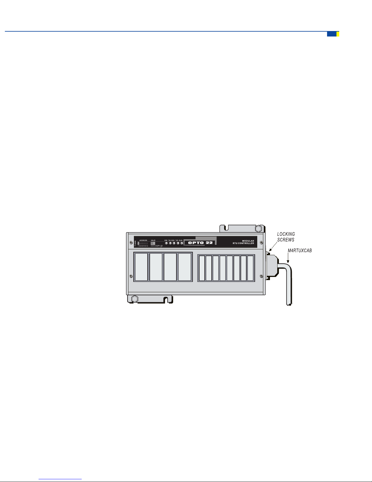
CONNECTING THE M4RTUXCAB
CABLE TO THE M4RTU/M4 I/O BASE UNIT
The optional M4RTUX I/O Extender Unit expands the number of input/output points available to the M4RTU/
M4 I/O from eight digital and four analog to 16 digital and eight analog.
If you plan to install the M4RTUX, you should attach the connecting cable (the M4RTUXCAB, packaged with the
M4RTUX) to the M4RTU/M4 I/O before mounting the base unit. You can then elect to mount the extender unit
right away or at some later time.
Brief procedures for connecting the M4RTUXCAB cable are provided below, along with a diagram illustrating
where the cable should be attached. For complete details on installing the M4RTUX, see Modular Controller
I/O Extender Data Sheet (form 671).
1. Locate the I/O Extender connector. This 25-pin D-shell connector can be found on the same end of the
M4RTU/M4 I/O as the power supply connector.
INSTALLATION AND SETUP
2. Align the M4RTUXCAB connector with the I/O Extender connector on the base unit and seat properly.
3. Tighten the M4RTUXCAB connector locking screws to secure the cable to the base unit.
Figure 3-9: M4RTUXCAB Cable Connected to the M4RTU/M4 I/O Base Unit
M4RTU/M4 I/O User’s Guide 41
Page 42

INSTALLATION AND SETUP
MOUNTING THE M4RTU/M4 I/O BASE UNIT
Two flanges are located on the upper right and lower left back sides of the M4RTU/M4 I/O. Each flange has two
mounting slots that can be used to fasten the M4RTU/M4 I/O to any enclosure or panel, either vertically or
horizontally.
Note: Be sure to install the power supply, any optional expansion cards, and the M4RTUXCAB on the M4RTU/
M4 I/O before mounting the unit.
The general procedure for mounting the M4RTU/M4 I/O base unit is as follows:
1. Determine panel mounting site and orientation (horizontal or vertical). Be sure to allow room for
external connectors.
2. Tape the supplied mounting template onto the M4RTU/M4 I/O panel and prick-punch mounting
locations.
3. Remove template and drill preliminary pilot holes.
4. Drill and tap (or drill through holes) for 1/4-20 screws.
5. Place M4RTU/M4 I/O onto mounting site and fasten with user-supplied 1/4-20 screws or screw and nut
assemblies.
42 M4RTU/M4 I/O User’s Guide
Page 43

INSTALLATION AND SETUP
Figure 3-10: M4RTU/M4 I/O Dimensions and Mounting Information
M4RTU/M4 I/O User’s Guide 43
Page 44
INSTALLATION AND SETUP
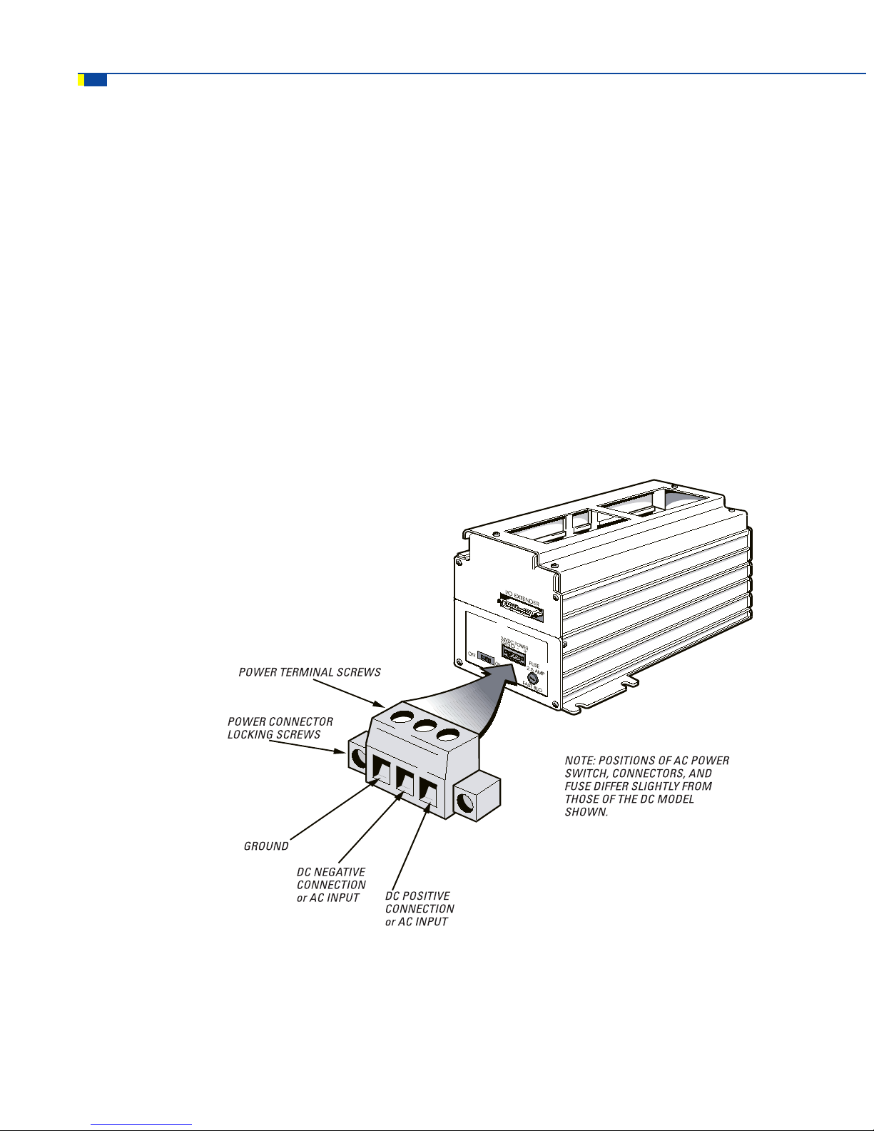
CONNECTING POWER TO THE M4RTU/M4 I/O
Once you have mounted the M4RTU/M4 I/O, you are ready to connect power to the unit. Refer to Figure 3-11.
1. Turn off the power supply switch.
2. Make sure all power supply terminal block connections are completely open by turning the power
terminal screws counterclockwise.
3. Prepare each power supply wire, being careful not to strip back the insulation too far.
4. Insert each wire into the appropriate terminal block location and tighten by turning the power terminal
screw clockwise. Make sure the terminal block is clamping the wire and not the insulation.
5. Tighten power connector locking screws.
Note that steps 2–4 may be performed with the power supply connector removed from the power supply. Once
steps 2–4 are complete, plug the power supply connector back into the M4RTU/M4 I/O and proceed to step 5.
44 M4RTU/M4 I/O User’s Guide
Figure 3-11: Connecting Power to the M4RTU/M4 I/O
Page 45

INSTALLING I/O MODULES
Caution: TURN OFF POWER to the M4RTU/M4 I/O before installing or removing I/O modules.
The M4RTU/M4 I/O board, located at the top of the unit just below the top cover, accommodates eight digital
and four analog G4 input/output modules. The placement for these modules is shown below.
To install I/O modules, you do not need to remove the top cover, unless you will be changing field wiring at the
same time.
Install each digital or analog module as follows:
1. Choose the appropriate channel location on the M4RTU/M4 I/O board and carefully line up the I/O
module pins with the sockets on the I/O board.
2. Press the module firmly into place until it seats all the way down on the I/O board.
3. Use a Phillips screwdriver to tighten the screw that will secure the I/O module.
INSTALLATION AND SETUP
Figure 3-12: Placement of Digital and Analog Modules
M4RTU/M4 I/O User’s Guide 45
Page 46

INSTALLATION AND SETUP
CONNECTING FIELD WIRING
To access the field wiring terminals, you will first need to remove the top cover of the M4RTU/M4 I/O by
removing the four corner screws at the top of the unit.
The pluggable field wiring terminals are located on the top of the M4RTU/M4 I/O board next to the corresponding
digital or analog channels. These terminals allow field wires to be connected to the installed I/O modules.
Figure 3-13 shows the location of the terminals on the unit and the layout of the terminal points as they
correspond to each I/O module.
Specific information on wiring digital and analog modules follows. For more detailed wiring information,
refer to Chapter 5 (Field Wiring).
46 M4RTU/M4 I/O User’s Guide
Figure 3-13: Locations of Terminals on the M4RTU/M4 I/O
Page 47

INSTALLATION AND SETUP
Digital Modules
Digital modules have two terminals corresponding to each module. Figure 3-14 shows a G4IDC5 digital input
module in channel zero wired with VIN + on terminal #1 and VIN - on terminal #2.
Figure 3-14: Digital Module Terminals
Analog Modules
Analog modules can use up to four terminals per I/O point. Figure 3-15 shows a G4AD6 0-5 VDC analog input
module in channel zero wired with VIN - on terminal #2 and VIN + on terminal #4. Refer to Chapter 5 for wiring
other analog modules.
Figure 3-15: Wiring for Analog Module G4AD6
M4RTU/M4 I/O User’s Guide 47
Page 48

INSTALLATION AND SETUP
CONNECTING TO A HOST PC OR MODEM
The M4RTU/M4 I/O features two built-in serial ports, COM0 (RS-232) and COM1 (RS-485), with a data transfer
rate of 300 Bd to 115.2 Kbps. Two additional serial ports are available by installing an optional M4SSER serial
expansion card into one of the M4RTU/M4 I/O expansion card slots. (See Chapter 4 for complete information.)
Wiring
Important: Serial port connectors wired for other Opto 22 controllers may not be compatible with the M4RTU/
M4 I/O. Use the M4RTU/M4 I/O connectors provided and refer to the diagrams in this manual
for wiring information.
The following sections describe wiring for the serial ports found on the M4RTU/M4 I/O base unit. Use Tables
3-3 and 3-4 as a reference for wiring the pluggable, 7-terminal serial port connectors, shown in Figure 3-16.
RS-232 COM0 Pin Connections
The M4RTU/M4 I/O has one built-in RS-232 COM0 serial port. Table 3-4 contains descriptions for each
COM0 pin.
Important: If RTS and CTS are not used, RTS must be connected to CTS (COM0 only) on the M4RTU/
M4 I/O.
48 M4RTU/M4 I/O User’s Guide
Figure 3-16: 7-Terminal Serial Port Connector s
Page 49

PIN CONNECTIONS/DESCRIPTIONS
Table 3-4: Pin Descriptions for the M4RTU/M4 I/O COM0 Serial Port
Pin COM0
1 Data Carrier Detect (DCD)
2 Transmit (TX)
3 Receive (RX)
4 Request-to-Send (RTS)
5 Clear-to-Send (CTS)
6 Data Terminal Ready (DTR )
7 Ground (GND)
INSTALLATION AND SETUP
RS-485 COM1 Pin Connections
An RS-485 COM1 port is also built into the M4RTU/M4 I/O base unit. Table 3-5 contains descriptions for each
COM1 pin for both 2-wire and 4-wire modes.
Note that the interrupt lines can be used to add interrupt capability to Opto 22 I/O units connected to an
M4RTU/M4 I/O via an RS-485 serial link (remote).
Table 3-5: Pin Descriptions for the M4RTU/M4 I/O COM1 Serial Port
Pin 2-wire Mode 4-wire Mode
1 Transmit/Receive Plus (TX/RX +) Transmit Plus (TX +)
2 Transmit/Receive Minus (TX/RX -) Transmit Minus (TX -)
3 Common Ground (GND) Common Ground (GND)
4 No Connection (N/C) Receive Plus (RX +)
5 No Connection (N/C) Receive Minus (RX -)
6 Interrupt Plus (IRQ +) Interrupt Plus (IRQ +)
7 Interrupt Minus (IRQ -) Interrupt Minus (IRQ -)
M4RTU/M4 I/O User’s Guide 49
Page 50

INSTALLATION AND SETUP
Wiring to a Host PC
This section provides information on wiring connections between an M4RTU/M4 I/O and a host personal
computer. Examples show connections to a standard PC serial port and an Opto 22 AC37.
Be sure to use cable appropriate to your application. See Appendix B for a complete list of recommended
cables.
RS-232 COM0
Make RS-232 communication connections to a host PC by using the RS-232 COM0 default host connector on
the M4RTU/M4 I/O.
Refer to Figure 3-17 to connect the M4RTU/M4 I/O to the serial port of a host PC. Verify that the pin connections
at the host PC are the same as those called out in the diagram.
Important: If RTS and CTS are not used, RTS must be connected to CTS (COM0 only) on the M4RTU/M4
I/O, as shown below.
50 M4RTU/M4 I/O User’s Guide
Figure 3-17: RS-232 Wiring to a Host PC
Page 51

INSTALLATION AND SETUP
RS-485 COM1
4-Wire Mode Using an AC37
If you are using an Opto 22 AC37, connect the end of the cable with a male 9-pin D-shell connector to the
converter and the other end with a pluggable terminal block to the M4RTU/M4 I/O. Refer to Figure 3-18 and
Figure 3-19 for wiring details.
Figure 3-18: RS-485 Wiring to a Host PC in 4-Wire Mode Using an AC37
2-Wire Mode Using an AC37
The AC37 also supports a 2-wire mode. Refer to the following diagram for wiring.
Figure 3-19: RS-485 Wiring to a Host PC in 2-Wire Mode Using an AC37
M4RTU/M4 I/O User’s Guide 51
Page 52

INSTALLATION AND SETUP
WIRING TO A MODEM (A DCE DEVICE)
Refer to your modem documentation for detailed wiring information, possible jumper configuration, and
initialization setup. You may also wish to refer to Opto 22’s communication application notes, available through
Opto 22’s Bulletin Board Service (see Appendix G for details).
Most standard external PC modems can be usd with the M4RTU/M4 I/O. However, a custom (or special)
communications cable must be used between the modem and the M4RTU/M4 I/O. Wiring diagrams for this
cable are shown below:
52 M4RTU/M4 I/O User’s Guide
Page 53

Computer (DTE) RS-232 COM Port Pin Assignments
RS-232 25-pin
Pin Na me Abbrevia tion
1 P ro te ctive Groun d - --- --- --2 Transm itte d D at a TD
3 Received Data RD
4 Request to Send RTS
5 Clear to Send CTS
6 Data Set Ready DSR
7 Sig na l Co m mo n ---- --- --8 Data Carrier Detect DCD
20 Data Terminal Ready DTR
22 R in g In di ca tor R I
INSTALLATION AND SETUP
RS-232 9-pin
Pin Na me Abbreviation
1 Data Carrier Detect DC D
2 R e ce ive d Da ta RD
3 Transm itte d D at a TD
4 Data Terminal Ready DTR
5 Sig na l Gr ou nd ---- --- --6 Dat Set Ready DSR
7 Request to Send RTS
8 Clear to Send CTS
9 R in g In di ca tor R I
M4RTU/M4 I/O User’s Guide 53
Page 54

INSTALLATION AND SETUP
CONNECTING TO OPTO 22 I/O UNITS
The built-in RS-485 COM1 port can be used as a serial link (remote) to communicate with Opto 22 digital or
analog I/O. A M4SSER serial expansion card installed in the M4RTU/M4 I/O can also be used for this purpose.
One method for doing this is to use a Mistic 200 I/O Remote Interface board (G4IOR) as illustrated in Figure
3-20. This method allows the use of Opto 22 I/O equipment (G4 panels, cables, etc.).
Figure 3-20 shows a 2-wire RS-485 shielded connection from COM1 on the M4RTU/M4 I/O to the G4IOR
Remote Interface board. Connect Pin 1 (TX/RX+) to G4IOR “TH+,” Pin 2 (TX/RX-) to G4IOR “TH-,” and Pin 3 to
“COM.” If you are using the interrupt lines, connect Pin 6 to “IRQ+” and Pin 7 to “IRQ-.”
Note: Refer to cable
specifications in
Appendix B.
Figure 3-20: Communications to a Remote Interface (G4IOR)
54 M4RTU/M4 I/O User’s Guide
Updated: 12/18/00
Page 55

INSTALLATION AND SETUP
Another method for using the RS-485 COM1 port as an RS-485 serial link (remote) is to use Opto 22 I/O units
installed with a SBTA, as illustrated in Figure 3-21. This allows you to accommodate your own installation
practices, application requirements, and cables. Simply mount your I/O units throughout your installation and
daisy chain communication cable between them. Refer to the
Mistic 200 Systems Installation Guide
for more
SBTA details.
Note: Refer to cable
specifications in
Appendix B.
Figure 3-21: Opto 22 I/O Units Installed with SBTA
Updated: 12/18/00
M4RTU/M4 I/O User’s Guide 55
Page 56

INSTALLATION AND SETUP
LED INDICATORS
Five LEDs are located on the top of the M4RTU/M4 I/O, in line with the configuration jumpers, as shown in
Figure 3-24. These LEDs perform the functions displayed in Table 3-6 below.
Figure 3-22: LED Indicators on the M4RTU/M4 I/O
Table 3-6: LED Functions
LED Indication
This indicator shows processor status. When the processor
RUN
(Processor status)
TX0
(COM0 transmit)
RX0
(COM0 receive)
TX1
(COM1 transmit)
RX1
(COM1 receive)
is functioning normally, the light stays on. When the
processor is powered down, the light goes off. If the light
blinks, it could indicate a processor malfunction or low power
supply voltage.
This indicator illuminates whenever COM0 is transmitting
serial data. If the LED fails to illuminate, it could indicate that
the port is idle, a wiring problem exists, or CTS is low.
This indicator illuminates whenever COM0 is receiving serial
data. If the LED fails to illuminate, it could indicate that the
port is idle or a wiring problem exists.
This indicator illuminates whenever COM1 is transmitting
serial data. If the LED fails to illuminate, it could indicate that
the port is idle or a wiring problem exists.
This indicator illuminates whenever COM1 is receiving serial
data. If the LED fails to illuminate, it could indicate that the
port is idle or a wiring problem exists.
56 M4RTU/M4 I/O User’s Guide
Page 57

CHAPTER 4
SOFTWARE AND FIRMWARE
OVERVIEW
This chapter provides information on using OptoControl, OptoDisplay, and OptoServer with the M4RTU/M4 I/O.
OptoControl is used to program and debug M4RTU/M4 I/O control strategies. OptoDisplay is used to create
M4RTU/M4 I/O process operator interfaces running on the PC. OptoServer allows the user to construct complex
client/server architectures running multiple OptoDisplay sessions, DDE-aware applications (such as Microsoft
Excel), or third-party software packages with OptoServer driver capability. The tight integration between
OptoControl, OptoDisplay, and OptoServer not only makes all three software packages easy to use, it also
prevents multiple database entry errors, allows tag name validation, and takes full advantage of the M4RTU/
M4 I/O’s hardware capabilities.
The sophisticated firmware of both the main and I/O processors of the M4RTU/M4 I/O, along with flash
technology, enables a user to update the M4RTU/M4 I/O remotely with a new set of operating systems for the
main and I/O processors. The firmware also supports the ability to store a user’s strategy permanently into
flash memory.
Note: It is not the intent of this chapter to teach OptoControl programming and debugging, OptoDisplay
configuration and runtime operation, or overall OptoServer usage. Instead, this chapter presents
an overview of these topics, with enough details to get you started. For detailed information on these
subjects, refer to the appropriate Opto 22 user guides.
M4RTU/M4 I/O User’s Guide 57
Page 58

Software and Firmware
OPTOCONTROL
OptoControl is used to configure communications between the PC and the M4RTU/M4 I/O, configure the I/O
units and points, and develop and run your control strategy.
Configuring Communications to the M4RTU/M4 I/O
To download OptoControl strategies to the M4RTU/M4 I/O and debug them, you must first configure the
communication link between the host PC and the M4RTU/M4 I/O. Begin by deciding what type of physical
communication link will be used (ARCNET, RS-232, RS-485/422, or Ethernet). Next, install and configure
communication hardware between the host PC and the M4RTU/M4 I/O. (Refer to the appropriate PC and
M4RTU/M4 I/O documentation for communication hardware installation details.)
Once the hardware has been installed, OptoControl must be configured to communicate over the physical
communication link. Refer to Chapter 6 of the
M4RTU/M4 I/O.
OptoControl User’s Guide
to configure PC communications to the
Configuring the M4RTU/M4 I/O and M4RTUX
Before writing OptoControl strategies for the M4RTU/M4 I/O, you must inform OptoControl about the I/O
installed on or connected to the M4RTU/M4 I/O and, if applicable, the M4RTUX.
OptoControl must know how the I/O units are connected to a controller (i.e., via the parallel I/O bus [local] or
RS-485 serial link [remote]) as well as what type of module will be installed into each I/O channel on each unit.
Once OptoControl has this information, you may use the assigned I/O tag names to reference the I/O within an
OptoControl strategy.
Note that the multifunction digital I/O unit (M4RTU/M4 I/O digital I/O) is addressed as 0 and the multifunction
analog I/O unit (M4RTU/M4 I/O analog I/O) is addressed as 1 on the parallel I/O bus (local). Since there is no
external local bus on the M4RTU/M4 I/O, these are the only two valid local bus addresses. These addresses
are important during I/O configuration within OptoControl.
Configuring M4RTU/M4 I/O and M4RTUX I/O Units
The first step in configuring I/O is adding the I/O units. Follow the procedure listed in Chapter 6 of the OptoControl
User’s Guide to add an I/O unit. For the digital unit, the Type is G4 Digital Multifunction, the Port is Local, and
the Address is 0. For the analog unit, the Type is G4 Analog Multifunction , the Port is Local, and the Address
is 1. Remember that the digital I/O on the M4RTUX is on the same unit as the digital I/O on the M4RTU/M4
I/O, and the analog I/O on the M4RTUX is on the same unit as the analog I/O on the M4RTU/M4 I/O.
Configuring Additional I/O Units
Your system may have additional I/O units connected via the RS-485 serial link. Follow the procedure listed in
Chapter 6 of the
Remote 1, 2, or 3
used and the jumper settings.
OptoControl User’s Guide
58 M4RTU/M4 I/O User’s Guide
to add an I/O unit. For the configuration of these units, the Port is
depending on where the I/O is located. The Type and Address will depend on the hardware
Page 59

Software and Firmware
Figure 4-1: Representation of the M4RTU/M4 I/O and SNAP I/O
Configuring the I/O Points
Follow the procedure listed in Chapter 6 of the
Configure I/O Points
together support a maximum of only eight analog channels. This is because the M4RTU/M4 I/O electronics
does not support the analog extender capability of an analog multifunction I/O unit. Simply ignore analog
channels 8 through 15 of the
dialog box shows 16 analog channels even though the M4RTU/M4 I/O and M4RTUX
Configure I/O Points
Storing User Strategies into M4RTU/M4 I/O Flash EEPROM
User OptoControl strategies may be stored into flash memory instead of residing in RAM backed up by a
battery. Flash memory has the same robust attributes of EEPROM for remote installations. Strategies may be
developed for the M4RTU/M4 I/O in RAM, remotely downloaded and debugged, and then stored remotely in
flash memory. If the M4RTU/M4 I/O has been set up to boot automatically from flash memory, the OptoControl
strategy stored in flash will be executed upon power-up.
To store an OptoControl strategy into flash memory, refer to Chapter 9 of the
To configure the M4RTU to run the program automatically from flash, refer to Chapter 3, page 35.
OPTODISPLAY AND OPTOSERVER
Both OptoDisplay and OptoServer share the database generated by OptoControl. This database contains the
configuration information for communicating to the M4RTU/M4 I/O and referencing any strategy data items,
such as variables, I/O, PIDs, and event/reactions. This information is used by OptoDisplay to dynamically drive
a given graphic’s attributes. It is also used by OptoServer to communicate to an M4RTU/M4 I/O or an Opto 22
Controller Network of M4RTU/M4 I/Os and other Opto 22 controllers.
OptoControl User’s Guide
dialog box.
to add an I/O point. Notice that the
OptoControl User’s Guide
.
M4RTU/M4 I/O User’s Guide 59
Page 60

Software and Firmware
To attach OptoDisplay or OptoServer to an M4RTU/M4 I/O (or to an Opto 22 Controller Network containing
M4RTU/M4 I/Os), follow the standard procedures outlined in the OptoDisplay and OptoServer online help or
user’s guides for adding controllers. In short, you will be telling OptoDisplay and OptoServer which OptoControl
database to open to access the communication information and strategy data items.
For more details regarding OptoDisplay and OptoServer, refer to the
User’s Guide
.
UPDATING THE M4RTU/M4 I/O FIRMWARE
The M4RTU/M4 I/O consists of two processors, each running a unique real-time, event-driven operating system.
The main processor contains the firmware, which executes the control strategy generated by OptoControl. The
I/O processor contains the I/O firmware, which performs all of the various local I/O unit real-time tasks, such as
counting, PIDs, and event/reactions. Opto 22 continues to improve the firmware by adding functionality and
enhancing features.
The M4RTU/M4 I/O comes preloaded with both the current Opto 22 firmware and I/O firmware. The M4RTU/
M4 I/O also comes with two disks containing the current firmware files for both Cyrano and OptoControl. The
latest firmware files are also available on Opto 22’s web site. Refer to Appendix G for details.
Each processor has a boot loader stored into a nondestructive part of its flash memory. This boot loader enables
a user to update the firmware as Opto 22 makes new firmware files available. The firmware can be updated
either locally or remotely. This enables a user to update existing firmware, change a control strategy to take
advantage of a new firmware feature, and download and debug the new strategy without having to venture out
to an RTU site.
If you are using OptoControl, use the OptoTerm utility, included with this controller on the OptoUtilities disks, to
update the firmware. This utility can update either the main processor firmware (flash file) or the I/O processor
firmware (I/O flash file). For details on using OptoTerm, consult online help or Chapter 12 in the
User’s Guide.
OptoDisplay User’s Guide
and
OptoServer
OptoControl
If you are using Cyrano, use the Flash200 program on the disk packaged with this controller to update the
firmware. For details on using Flash200, consult online help.
The boot loader for the main processor currently supports COM0, COM1, ARCNET (coaxial), and Ethernet as
primary host ports for firmware updating. As new communication expansion daughter cards become available
from Opto 22, new flash chips with enhanced boot loaders will be developed to support them. The new flash
chips will need to be installed after removing the current flash chips located on the processor board of the base
unit. Refer to Appendix E for details on this procedure.
60 M4RTU/M4 I/O User’s Guide
Page 61

FIELD WIRING
OVERVIEW
This chapter provides detailed information on digital and analog field wiring for the M4RTU/M4 I/O and M4RTUX.
It includes examples of how to wire all currently-available G4 digital and analog I/O modules. (If a particular
module is not represented, please contact Opto 22 Product Support. See Appendix G for details.)
The M4RTU/M4 I/O and M4RTUX, shown in Figures 5-1 and 5-2 on the following pages, use pluggable screwstyle terminal blocks for field wiring. This type of terminal block provides users with the advantages of both a
terminal block and a connector. Terminal blocks furnish a robust individual wire attachment, while connectors
enable quick multi-wire disconnection. Hence, the pluggable screw-style terminal blocks provide easy installation
of field wiring and easy removal of the M4RTU/M4 I/O and M4RTUX should the need arise.
CHAPTER 5
A bused four-position pluggable terminal block is provided on both the M4RTU/M4 I/O and M4RTUX. This
bused terminal block is located between the two field wire terminal blocks and can be used to bus user power
or commons. It is not connected to any power source or ground plane on the M4RTU/M4 I/O or M4RTUX.
The terminal blocks for each unit reside under a cover, preventing removal without the use of a tool. When
attaching field wiring, make sure that the M4RTU/M4 I/O is off and that field wiring is not powered, especially
in hazardous environments. Field wiring should be properly prepared for terminal block installation, it should be
accurately labeled, and it should be neatly dressed. Allow for adequate service loops in all field, power, and
communication wiring.
If you will be connecting the M4RTU/M4 I/O to additional I/O units via the RS-485 serial link (remote), refer to
Mistic 200 Systems Installation Guide
the
and the
Mistic 200 Family Data Book.
M4RTU/M4 I/O User’s Guide 61
Page 62

FIELD WIRING
Figure 5-1: Locations of Terminals on M4RTU/M4 I/O Showing
Logical Representation of Modules
62 M4RTU/M4 I/O User’s Guide
Figure 5-2: Locations of Terminals on M4RTUX Showing
Logical Representation of Modules
Page 63

FIELD WIRING TERMINALS
The M4RTU/M4 I/O and M4RTUX field wiring terminals are located at the top of each unit, next to their
corresponding digital and analog channel locations. Together, the M4RTU/M4 I/O and M4RTUX represent a full
complement of 16 digital and 8 analog channels, equivalent to the number of channels on a standard
digital and one analog brick. (Although the M4RTU/M4 I/O electronics can support a full complement of digital
and analog channels, the unit does not have enough space to support these channels, hence the need for the
M4RTUX I/O Extender.)
Note that although the I/O channels on the M4RTU/M4 I/O and the M4RTUX are labeled identically, these
channels actually represent different modules logically. Hence, on the M4RTU/M4 I/O, the digital channels
labeled 0–7 and the analog channels labeled 0–3 correspond correctly to digital modules 0–7 and analog
modules 0–3, while on the M4RTUX, the channels with the same labels correspond logically to digital modules
8–15 and analog modules 4–7.
Each digital channel has two terminals and each analog channel has four terminals. As with the I/O channels
themselves, the terminals corresponding to these channels are also labeled identically on the M4RTU/M4 I/O
and M4RTUX, even though they represent different terminal connections. Hence, on the M4RTU/M4 I/O, the
terminals labeled 1–16 correspond correctly to terminal connections 1–16, while on the M4RTUX, these terminals
correspond logically to terminal connections 17–32.
FIELD WIRING
set of one
.
Figures 5-1 and Figure 5-2 show the location of the digital and analog channels, as well as their corresponding
terminals for both the M4RTU/M4 I/O and M4RTUX. See also Appendix F for field wiring worksheets.
For additional wiring and module specification information, refer to the
and the
Mistic 200 Family Data Book
.
Mistic 200 Systems Installation Guide
M4RTU/M4 I/O User’s Guide 63
Page 64

FIELD WIRING
CONNECTING FIELD WIRING
To connect field wiring to the M4RTU/M4 I/O and M4RTUX terminals, follow the procedures below. See Figure
5-3 for reference.
1. Access the field wiring terminals by removing the four corner screws at the top of the M4RTU/M4 I/O
or M4RTUX and removing the top cover.
2. Refer to the appropriate section in this chapter for the specific model of G4 digital or analog module for
which wiring will be connected. Also, refer to Appendix F for a field wiring worksheet.
3. Ensure that each terminal is completely open by turning the captive screw counterclockwise until it
stops.
4. Insert each wire into the appropriate terminal block location and tighten by turning the power terminal
screw clockwise. Make sure the terminal block is clamping the wire and not the insulation.
64 M4RTU/M4 I/O User’s Guide
Figure 5-3: Field Wiring for the M4RTU/M4 I/O and M4RTUX
Page 65

WIRING DIGITAL MODULES
Each digital I/O channel has two terminals corresponding to each installed digital module. Terminals 1 and 2
correspond to a module in channel 0, terminals 3 and 4 correspond to a module in channel 1, and so on. For
polarized modules, the positive connection goes to the first terminal of the pair and the negative connection
goes to the second. This wiring scheme is identical for the M4RTUX, starting with channel 8.
Input Modules
Use Figure 5-4 on the following page to wire the digital DC and AC input modules listed in Table 5-1. The
diagram shows a DC input module wired to channel 0 and an AC input module wired to channel 1 on the
M4RTU/M4 I/O.
For the digital input modules listed in Table 5-1, the input device may be wired to either terminal. The polarity
of the power does not matter except for the G4IDC5K and G4IDC5D.
Table 5-1: DC and AC Input Modules
FIELD WIRING
DC Input
Modules
G4IDC5 G4IAC5
G4IDC5K G4IAC5A
G4IDC5D G4IAC5MA
G4IDC5B -----G4IDC5G ------
G4IDC5MA ------
AC Input
Modules
Output Modules
Use Figure 5-4 to wire the digital DC and AC output modules listed in Table 5-2. The diagram shows a DC output
module wired to channel 6 and an AC output module wired to channel 7 on the M4RTU/M4 I/O.
For the digital output modules listed in Table 5-2, the load may be wired to either line.
Table 5-2: DC and AC Output Modules
DC Output
Modules
G4ODC5 G4 OAC5
G4OD C5A G4OAC5A
G4ODC5M A G4OAC5A5
G4ODC 5R G4OAC5MA
G4ODC5 R5 G4O AC5AM A
AC O utput
Modules
M4RTU/M4 I/O User’s Guide 65
Page 66

FIELD WIRING
Figure 5-4: Wiring for DC and AC Input/Output Modules
For DC output modules used with inductive loads, add a commutating diode (typically a 1N4005) to the circuit
as shown on the channel 6 connection to the M4RTUX.
66 M4RTU/M4 I/O User’s Guide
Page 67

FIELD WIRING
Quadrature Input Module
Use Figure 5-5 to wire the digital quadrature input module (model G4IDC5Q). The example shows the module
connected to channels 8 and 9 on the M4RTUX.
Note: This module requires two digital channels.
Figure 5-5: Wiring for Digital Quadrature Input Modules
M4RTU/M4 I/O User’s Guide 67
Page 68

FIELD WIRING
WIRING ANALOG MODULES
Analog modules use up to four terminals per analog I/O channel. The following wiring diagrams illustrate field
wiring schemes for each type of analog I/O module.
Voltage Input and Output Modules
Use Figure 5-6 to wire the analog voltage input or output modules listed in Table 9-3. The diagram shows a
voltage input module wired to channel 0, and a voltage output module wired to channel 3 on the M4RTU/
M4 I/O.
Table 5-3: Voltage Input and Output Modules
Analog Voltage
Input Module
G4AD6HS G4DA5
G4AD7HS G4DA7
G4AD11 - - -
G4AD12 - - -
G4AD13 - - -
G4AD22 - - -
G4AD25 - - -
68 M4RTU/M4 I/O User’s Guide
Figure 5-6: Wiring for Voltage Input and Output Modules
Analog Voltage
Output Modules
G4AD6 G4DA4
G4AD7 G4DA6
G4AD9 - - -
Page 69

FIELD WIRING
Milliamp Current Input and Output Modules
Use Figure 5-7 to wire the analog milliamp current input or output modules listed in Table 5-4. The example
shows wiring to the M4RTU/M4 I/O on channels 0 through 3.
The current loop for an input or output current device can be powered either by a user’s external supply or by
the module. Using the module reduces wiring expense.
Figure 5-7: Wiring for Milliamp Current Input and Output Modules
Table 5-4: Milliamp Current Input and Output Modules
Input
Modules
G4AD3 G4DA3
------ G4DA8
Analog mA
Current Outputs
M4RTU/M4 I/O User’s Guide 69
Page 70

FIELD WIRING
0 to 5 Amp AC/DC Current Input
The 0–5A AC/DC current input module can be used to measure current directly or indirectly through a standard
current transformer. Applications include measuring or monitoring current through a field device such as a
motor, solenoid, or lamp.
Use Figure 5-8 to wire a 0–5A AC/DC current input module (model G4AD16). The example shows wiring of the
G4AD16 to channel 0 on the M4RTU/M4 I/O.
Figure 5-8: Wiring for Velocity Input
and 0–5A AC/DC Input Modules
Velocity Input
The velocity input module (model G4AD26) indicates a change in voltage by providing the first derivative of
voltage with respect to time (dV/dt). Typically, potentiometer-based transducers are attached. An example of
an application would be a transducer measuring piston velocity in an air/hydraulic cylinder.
Use Figure 5-8 to wire the velocity input module. The example shows wiring of the G4AD26 to channel 3 on the
M4RTU/M4 I/O.
Thermocouple Input
Use Figure 5-9 to wire the analog thermocouple input modules listed in Table 5-5. The example shows a
thermocouple input module wired to channel 3 on the M4RTU/M4 I/O.
When wiring thermocouples, verify that you are using the proper polarity and wire color (see Table 5-5). Also
ensure that the wire type from the thermocouple to field terminals is consistent and does not introduce other
thermocouples.
70 M4RTU/M4 I/O User’s Guide
Page 71

FIELD WIRING
Note: Do not use a cold junction compensator with a G4AD24.
ICTD Temperature Input Module
Use Figure 5-9 to wire the ICTD temperature input module (model G4AD4) to an Opto 22 ICTD probe. The
example shows wiring to channel 0 on the M4RTU/M4 I/O.
Figure 5-9: Wiring for 100-Ohm RTD Input Modules
Table 5-5: Thermocouple Input Data
Model
G4AD5 J white red
G4AD8 K yellow red
G4AD17 R black red
G4AD18 T blue red
G4AD19 E purple red
G4AD23 S black red
G4AD24 B gray red
T/C
Type
Polarity/Color
+
-
M4RTU/M4 I/O User’s Guide 71
Page 72

FIELD WIRING
100-Ohm RTD Input Module
Use Figure 5-10 to wire an analog 100-ohm RTD input module (model G4AD10). Wire colors may vary, but make
sure two wires of the same color are connected as shown. The example shows a three-wire RTD probe connected
to channel 4 and a two-wire RTD connected to channel 7 on the M4RTUX.
For a four-wire RTD probe, do not connect the fourth wire. Connect three wires as shown for the three-wire RTD
example.
For a two-wire RTD probe, add a second wire of the same type and gauge to one end, connecting it as you
would a three-wire RTD. The example shows this type of connection to channel 7 on the M4RTUX.
Rate Module
The rate module (model G4AD20) measures the frequency of an incoming signal and produces a count based
on the number of cycles per second (Hertz). For example, a count value of 1,000 indicates a frequency of 1,000
Hz. This module is ideal for directly reading the frequency of a signal or a rotating disk for RPM calculations,
for example.
The input amplitude range from a transducer generating a square or sine wave can be changed by adding a
jumper to the hookup. Refer to the wiring example connected to channel 4. The square wave input range
changes from 0.5 to 24 V
.
24 V
p-p
72 M4RTU/M4 I/O User’s Guide
Figure 5-10: Wiring for 100-Ohm RTD Input Modules
to 0.25 to 24 V
p-p
. The sine wave input range changes from 5 to 24 V
p-p
to 2.5 to
p-p
Page 73

FIELD WIRING
Use Figure 5-11 as a guide to wiring the G4AD20 analog rate module. The example shows the possible wiring
options to channels 4 and 7 on the M4RTUX.
Figure 5-11: Wiring for Rate Modules
Time Proportional Output Module
The time proportional output modules switch either 5–60 VDC (G4DA9) or 12–280 VAC (G4DA10). Together
with power SSRs, they are ideal for temperature control applications, such as heating.
Use Figure 5-12 to wire either of the analog time proportional output modules. The example shows a G4DA10
wired to channel 3 and a G4DA9 wired to channel 0 on the M4RTU/M4 I/O.
Figure 5-12: Wiring for Time Proportional Output Modules
M4RTU/M4 I/O User’s Guide 73
Page 74

FIELD WIRING
74 M4RTU/M4 I/O User’s Guide
Page 75

APPENDIX A
TROUBLESHOOTING
Table A-1: M4RTU/M4 I/O Troubleshooting Chart
Indication Condition/Problem Action
RUN LED stays off. Power not applied to processor. Check power supply connections.
RUN light flashes. Not enough power or malfunction. Verify power supply voltage.
RUN LED flashes after a kernel
(firmware) is downloaded or power
failure oc curred during EEPROM
firmware installation.
TX0 (COM0 transmit) LED stays off. Port not transmitting. Cycle power to unit. Check CTS connection;
RX0 (COM0 receive) LED stays off. Port is idle.
Host does not receive a response
from the M4RTU/M4 I/O, and RX0
or RX1 (COMO or COM1 receive)
LED flashes communications setup,
during program download.
TX1 (COM1 transmit) LED stays off. Port not transmitting. Cycle power to unit. Check jumper settings
RX1 (COM1 receive) LED stays off. Port is idle.
M4RTU/M4 I/O controller cannot
transmit to PC.
Kernel (firmware) is corrupted. Remove Boot Loader jumper so that
M4RTU/M4 I/O boots to loader. Reinstall
EEPROM firmware, then reinstall Boot Loader
jumper.
must be connected to RTS if not used. Check
jumper settings and/or controller
communications setup.
Check wiring for polarity transposition.
Wire or connection is bad.
PC to M4RTU/M4 I/O connections
are incorrect.
Incorrect setup in the OptoControl
controller configurations.
Wire or connection is bad.
Configuration jumpers were
changed without cycling power.
Wiring to serial port is incorrect.
Check connections at terminals.
Check wiring connections for correct polarity
and wire integrity.
Check controller configurations; specifically
baud rate, address, and binary/ASCII settings.
and/or controller communications setup.
Check wiring for polarity transposition.
Check connections at terminals.
Cycle power and retry transmission.
Check wiring for possible polarity transposition.
Digital output is not working. Bad module fuse.
Output does not work with
G4SWOUT module installed.
Wrong module type. Incorrect
wiring.
Load does not work with voltage
applied. Output is wired wrong.
Re plac e fuse.
Make sure module is 5V (G4ODC5 is correct,
G4ODC24 is incorrect) Match the output
module with the load. Use G4SWOUT module
to troubleshoot. If G4SWOUT works, contact
Opto 22 Product Support (see Appendix G).
Check field wiring worksheets (see Appendix F)
and rewire, if necessary.
M4RTU/M4 I/O User’s Guide 75
Page 76

TROUBLESHOOTING
Table A-1: M4RTU/M4 I/O Troubleshooting Chart (continued)
Indication Condition/Problem Action
Digital input is not working. Input device is not working
properly.
Wrong module type.
Voltage on input is not
compatible with module voltage
range.
I/O or processor board is bad.
Digital input test with
G4SWIN module installed.
Analog output is not working. Output is wired incorrectly.
Analog input is not working. Voltage output device is wired
I/O or processor board is bad. Contact Opto 22 Product Support (see Appendix G).
Device is not properly matched
to module type.
I/O or processor board is bad.
incorrectly.
Thermocouple has a break.
Check input device wiring and power source. Rewire,
replace, or fix power source as needed.
Make sure module is 5V (for example, [G4IDC5 is
correct, G4IDC24] is incorrect).
Change voltage to match module or module to match
voltage.
Use G4SWIN module and OptoControl or G4TEST to
send commands to the M4RTU/M4 I/O to verify that the
processor board and I/O board are working properly.
Check wiring to output device. Test module using meter
and test software (OptoControl or G4TEST). Change
voltage to match module or module to match voltage.
Contact Opto 22 if meter reading does not change with
value change in test software.
Check device and wiring. Connect voltage source or
current source (depending on input type) and use test
software to determine if input is functioning.
For a thermocouple, check for continuity across test
points next to module.
RTD has open or incorrect
wiring.
I/O or processor board is bad.
For an RTD input, check resistance across test points
next to module.
Contact Opto 22 Product Support if any of the following
occurs:
- If value in test software does not change with input
when testing input voltage or current with test software.
- If thermocouple has continuity across test points.
- If resistance across test points is about 100 ohms for
RTD input.
76 M4RTU/M4 I/O User’s Guide
Page 77

APPENDIX B
CABLE AND CONNECTOR
SPECIFICATIONS
SERIAL COMMUNICATION CABLES
The following cables are recommended for both RS-232 and RS-485/422 serial communications. Although you
may elect to use other cables, keep in mind that low capacitance (less than 15 pF/ft.) is important for highspeed digital communication links. The cables listed below are all 24-gauge, 7x32 stranded, with 100-ohm
nominal impedance and a capacitance of 12.5 pF/ft.
Select from the following two-, three-, and four-pair cables, depending on your application needs. All will yield
satisfactory results. It is recommended that you choose a cable with one more pair than your application
requires. Use one of the extra wires, rather than the shield, for the common.
Two-Pair:
• Belden P/N 8102 (with overall shield)
• Belden P/N 9729 (individually shielded)
• Belden P/N 8162 (individually shielded with overall shield)
• Manhattan P/N M3475 (individually shielded with overall shield)
• Manhattan P/N M39249 (individually shielded with overall shield)
Three-Pair:
• Belden P/N 8103 (with overall shield)
• Belden P/N 9730 (individually shielded)
• Belden P/N 8163 (individually shielded with overall shield)
• Manhattan P/N M3476 (individually shielded with overall shield)
• Manhattan P/N M39250 (individually shielded with overall shield)
Four-Pair:
• Belden P/N 8104 (with overall shield)
• Belden P/N 9728 (individually shielded)
• Belden P/N 8164 (individually shielded with overall shield)
• Manhattan P/N M3477 (individually shielded with overall shield)
• Manhattan P/N M39251 (individually shielded with overall shield)
M4RTU/M4 I/O User’s Guide 77
Page 78

CABLE AND CONNECTOR SPECIFICATIONS
M4RTU/M4 I/O CONNECTORS
The following connectors are included with the M4RTU/M4 I/O:
Green Pluggable 7-Position Terminal Mini-Plug
• Used for RS-232 and RS-485/422 connections from the M4RTU/M4 I/O (COM0 and COM1) and the
M4SSER (COM2 and COM3)
• Manufactured by Phoenix Contact (P/N MC1, 5/7-ST-3, 81)
Green Pluggable 3-Position Terminal Plug
• Used for M4RTU/M4 I/O power connection
• Manufactured by Phoenix Contact (P/N MSTB 2, 5/3-STF-5, 08)
Green Pluggable 16-Position I/O Connector
• Used for wiring from the M4RTU/M4 I/O and M4RTUX to field application hardware
• Manufactured by Phoenix Contact (P/N MVSTBR 2, 5/16-ST-5, 08)
78 M4RTU/M4 I/O User’s Guide
Page 79

APPENDIX C
PRODUCT SPECIFICATIONS
Table C-1: M4RTU/M4 I/O Base Unit Hardware Specifications
Item Specification
32-bit Motorola 68020 processor
CPU
CPU clock frequency 16.67 MHz
Memory:
RAM
Flash EEPROM on controller
Flash EEPROM on brain board
16-bit 80C196 I/O processor
IEEE floating-point math
1 MB with battery backup (use r programs & data)
256 KB - 1 MB (firmware and user programs)
128 KB (I/O firmware)
RAM /clock battery 3.6-volt lithium, non-rechargeable
I/O:
Base unit
Extender unit
Expansion
Communication:
Base unit
Expansion
Modem support
Real-time clock Clock/calendar, Epson 6242 1A with batte ry backup
Power requirements
Typical operating temperature -20° C to 70° C
Storage temperature -40° C to 85° C
Hum idity 5% to 95% relative humidity
Software
System monitors:
Host communications
Watchdog timers
RAM battery backup low
Operating temperature
8 digital, 4 analog, multifunc tion
Adds 8 digital, 4 analog, mu ltifunction
Via RS-485 ports, using Opto 22 I/O
1 RS-232 and 1 RS-485/422 port
Via daughter cards: configurable serial ports and ARCNET
Direct, lease, and radio
5 VDC at 3.5 A (maximum)
24 VDC at 300 mA (maximum)
FactoryFloor (OptoControl, OptoDisplay, and Optoserver)
Classic Soft ware (Cyrano, Mistic MMI, and MDS)
Detect communication errors from processor, I/O, etc.
Detect main power supply ope ration
Detects program corruption (checksum RAM test)
Detects temperature
M4RTU/M4 I/O User’s Guide 79
Page 80

PRODUCT SPECIFICATIONS
80 M4RTU/M4 I/O User’s Guide
Page 81

APPENDIX D
ADDRESS JUMPER CONFIGURATION
The M4RTU/M4 I/O includes eight address jumpers, as described in Chapter 3. To set the jumpers based on a
predetermined address, refer to the chart below.
For details on accessing and setting these jumpers, see Chapter 3.
Figure D-1: M4RTU/M4 I/O Address Jumper Configurations
M4RTU/M4 I/O User’s Guide 81
Page 82

ADDRESS JUMPER CONFIGURATION
82 M4RTU/M4 I/O User’s Guide
Page 83

UPGRADING RAM
AND FLASH EEPROM
OVERVIEW
If the M4RTU/M4 I/O does not have a “1 MB RAM Installed” sticker, you can expand the M4RTU/M4 I/O RAM
from 256 KB to 1 MB. You can also expand the flash EEPROM from 256 KB to 1 MB. To do such an upgrade,
it is necessary to remove and disassemble the M4RTU/M4 I/O base unit to access the processor board where
the RAM and flash EEPROM chips are located. You can also use this process to upgrade the processor board
with flash chips containing new enhanced boot loaders supporting new primary host communication hardware
(e.g., fiber or Ethernet).
APPENDIX E
To disassemble the M4RTU/M4 I/O, follow these instructions:
1. Turn off the power to the M4RTU/M4 I/O.
2. Disconnect the incoming electrical power from the power supply.
3. Remove the four screws located on the top cover of the unit. Take off the top cover. Disconnect the field
wiring plug connectors.
4. Remove any communication port connectors and/or M4RTUXCAB cables.
* Do not change this jumper.
Figure E-1: Locations of Jumpers and Chips on the M4RTU/M4 I/O
M4RTU/M4 I/O User’s Guide 83
Page 84

UPGRADING RAM AND FLASH EEPROM
5. Remove the unit from its mounted position by removing the four user-supplied screw assemblies from
the mounting flanges.
6. Remove the top end cap on the power supply end of the M4RTU/M4 I/O base unit by removing the two
screws at the top corners of the end cap.
7. Grasp the edge of the I/O and processor boards and pull firmly until the two boards disengage from the
M4BUS and slide completely out of the M4RTU/M4 I/O enclosure.
8. Gently pull the I/O board up and away from the processor board to separate the two boards. (The I/O
board is parallel and on top of the processor board.) Carefully set the I/O board aside.
9. Using a chip puller, carefully remove the U13 and U15 chips for a RAM upgrade or the U12 and U14
chips for a flash EEPROM upgrade.
10. When upgrading flash EEPROM, install each chip in its correct position (U12 or U14). Each will be
marked with its position. (See Figure E-1.)
When upgrading RAM, you may install either chip in either position (U13 or U15).
Note: Ensure that the chips are correctly oriented; the notch on the chip should line up with the notch on the
silk screen on the board.
11. After correctly positioning each chip, make sure it is securely seated; however, do not attempt to force
or bend the chip in place!
12. Once all chips are physically installed, set the jumpers located on the processor board to correspond to
the new RAM or flash EEPROM size. See “Setting Configuration Jumpers and Switches” in Chapter 3
and refer to Table 3-2 for proper jumper settings.
13. To put the unit back together, undo steps 1–8 in reverse order.
84 M4RTU/M4 I/O User’s Guide
Page 85

Use Table E-1 to select RAM expansion options for your controller.
Table E-1: RAM Expansion Options
UPGRADING RAM AND FLASH EEPROM
R
G4LC32 G4LC32SX G4LC32ISA M4RTU/M4IO/M4
A
M
Size
Original
256K N/A N/A
512K
Configuration
1M G4LC32RAMEX5M
2M N/ A
4M G 4 LC 32 RAMEX4M
Base
1
New
1
Original
2
Base
Base
Configuration
Buy 4
G4RA M1M
Buy 4
G4RA M4M
G4RA M4M
Configuration
N/A N/A
N/A
N/A N/A
N/A N/A N/ A N /A N/ A
Configuration
G4R AM4M G4RAM4M G 4RAM4M
Use Table E-2 to select EPROM expansion options for your controller.
Table E-2: EPROM Expansion Options
G4LC32 G4LC32SX G4LC32ISA
Size
New
Base
Buy2
2
____________ Original
Base
Configuration
configuration
G4RAM1M
3
Base
New
N/A
N/A N/A
3
Base
Configurat ion
Buy 4
G4RAM 4M
N/A N/A
M4RTU/
M4IO/M4
Original New (Flash) Original New (Flash) Flash Flash
128K Base Configuration N/A
256K Buy 4 27C512-120
512K Buy 4 27C010-120
1M Buy 4 27C020-120
4
4
N/A N/A
Base
Configuration
4
G4LC32F1M N/A G4LC32SXF1M G4LC32ISAF1M M4RTUF1M
Notes:
1
= Chips from Intel (N/A from Opto 22). Older chips had a 256K base configuration.
2
= See attached to determine if you have a new style G4LC32/G4LC32SX or old style G4LC32/G4LC32SX.
3
= New controllers are marked with a “1MB RAM installed” sticker.
Base
Configuration
N/A N/A N/A
Base
Configuration
Base
Configuration
N/A N/A N/A N/A
M4RTU/M4 I/O User’s Guide 85
Base
Configuration
Page 86

UPGRADING RAM AND FLASH EEPROM
86 M4RTU/M4 I/O User’s Guide
Page 87

WORKSHEETS
The following worksheets can be used to plan I/O module installation for the M4RTU/M4 I/O base unit and
M4RTUX I/O extender unit.
Worksheet Instructions
Fill in the digital or analog I/O type in the box to the right of each I/O channel shown on the worksheet.
The following is an example of a completed worksheet:
APPENDIX F
* When configuring digital or analog I/O for the M4RTU/M4 I/O base unit using OptoControl, use these
addresses and make sure the PORT type is LOCAL. See Chapter 4 (Software and Firmware) for more
information.
Figure F-1: Sample I/O Module Worksheet
M4RTU/M4 I/O User’s Guide 87
Page 88

WORKSHEETS
* When configuring digital or analog I/O for the M4RTU/M4 I/O base unit using OptoControl, use these
addresses and make sure the PORT type is LOCAL. See Chapter 4 (Software and Firmware) for more
information.
88 M4RTU/M4 I/O User’s Guide
Figure F-2: M4RTU/M4 I/O Base Unit–I/O Module Worksheet
Updated: 7/9/99
Page 89

WORKSHEETS
Figure F-3: M4RTUX I/O Extender–I/O Module Worksheet
M4RTU/M4 I/O User’s Guide 89
Page 90

WORKSHEETS
FIELD WIRING WORKSHEET
The following worksheet can be used to plan and implement field wiring installation for the M4RTU/M4 I/O
base unit and M4RTUX I/O Extender.
Worksheet Instructions
Fill in the wire name boxes for each terminal. The Field Wiring Worksheet can be used by your installer during
RTU installation. If you need additional worksheets, make copies before filling this out.
90 M4RTU/M4 I/O User’s Guide
Figure F-4: Field Wiring Worksheet Example 1
Page 91

WORKSHEETS
Figure F-5: Field Wiring Worksheet Example 2
M4RTU/M4 I/O User’s Guide 91
Page 92

WORKSHEETS
Field Wiring Worksheet Examples
Hardware
M4RTU/M4 I/O Base Unit 7.5 1.0 7.5
M4RTUX I/O Extender Unit 0 0
Daughter Cards¹
M4SSER 1.6
M4SARC 1.0
M4SARCF 1.1
M4SARCFR 1.6
M4SENETC 3.1
M4SENETU 1.50
M4DUALARC 0.7
M4ENET100 4.1
Digital I/O Modules:
G4 Digital AC/DC Input/Output² 0.086
G4ODC5R, G4ODC5R5 0.10
G4IDC5Q 0.43
Analog I/O Modules:
G4ADX³ 1.6
G4AD3
Sourcing:
Non-Sourcing:
G4DA4
Sourcing:
Non-Sourcing:
G4DA3, G4DA8
Sourcing:
Non-Sourcing:
G4DA9, G4DA10 0.18
Powered RS-232 devices
(e.g., barcode reader)
Total Watts (TW):
Your supplied input voltage:
TW/Your supplied input voltage = Input Current _______A
Watts
(W)
2.6
1.6
2.2
1.1
2.6
1.2
Quantity
(Q)
To ta l
(W x Q)
_______W
_______V
¹If the daughter card you are using does not appear above, call Opto 22 for a data sheet or contact Opto 22
Product Support for wattage specifications.
²If the digital module you are using does not appear above, use the G4 Digital AC/DC Input Output module
wattage.
³If the analog module you are using does not appear above, use the G4ADX wattage.
92 M4RTU/M4 I/O User’s Guide
Page 93

M4RTU/M4 I/O POWER CONSUMPTION WORKSHEET
Instructions
1. On the previous worksheet, locate the daughter cards and digital and/or analog modules you will be
using with the M4RTU/M4 I/O. Enter a quantity for each item in the “Quantity” column. Also, fill in the
quantity and wattage of any RS-232 devices on the line provided.
2 . Multiply the value in the “Watts” column by the quantity entered in the “Quantity” column and enter
the result in the “Total” column for each component used.
Example: Eight G4 digital module totals 0.688 W. Four G4ADX analog modules total 6.4 W.
3. Add the values in the “Total” column, including the value entered for the M4RTU/M4 I/O base unit,
and enter the result on the “Total Watts” line.
Example: 0.688 W (digital modules) + 6.4 W (analog modules) + 7.5 W (base RTU) = 14.588 W.
WORKSHEETS
4. Enter the supplied input voltage for your installation on the “Your supplied input voltage” line.
Example: 24 VDC.
5. Divide the total on the “Total Watts” line by the number entered on the “Your supplied input voltage”
line to calculate your total input current requirements. Enter this number on the last line of the
worksheet.
Example: 14.588 W (total watts)/24 VDC (supplied input) = 0.6 A required input current for the
M4RTU/M4 I/O.
M4RTU/M4 I/O User’s Guide 93
Page 94

WORKSHEETS
94 M4RTU/M4 I/O User’s Guide
Page 95

PRODUCT SUPPORT
If you have any questions about this product, contact Opto 22 Product Support Monday through Friday,
8 a.m. to 5 p.m. Pacific Time.
Phone: 800-TEK-OPTO (835-6786)
Fax: 951-695-3017
E-mail: support@opto22.com
Opto 22 Web site: www.opto22.com
When calling for technical support, be prepared to provide the following information about your system to the
Product Support engineer:
APPENDIX G
951-695-3080
• Software and version being used
• Controller firmware version
• PC configuration
• A complete description of your hardware and operating systems, including:
— jumper configuration
— accessories installed (such as expansion daughter cards)
— type of power supply
— types of I/O units installed
— third-party devices installed (e.g., barcode readers)
• Specific error messages seen
M4RTU/M4 I/O User’s Guide 95
Page 96

PRODUCT SUPPORT
96 M4RTU/M4 I/O User’s Guide
Page 97

INDEX
A
address
jumpers 37, 81
analog I/O modules 10
wiring 47, 68
applications 12
ARCnet 11, 36, 58
expansion daughter cards 36
and baud rate jumper settings 36
ASCII communication mode 36
Autoboot jumper 36
B
battery 22
connecting 33–50
location 33
baud rate
jumpers 36
binary communication mode 36
boot loader 60
jumper 36
bulletin board service 95
C
cable specifications 77–78
client/server architecture 57
communication
configurations 13
configuring through OptoControl 27
mode
jumper 36
verifying 28
connecting field wiring 46–50, 64
connecting power to the M4RTU/DAS 44–50
connectors
specifications 78
control program 36, 57, 60
current input module 70
Cyrano 60
kernel 20
D
digital I/O modules 10
wiring 47, 65
E
Ethernet 11, 36, 58
expansion daughter cards
and baud rate jumper settings 36
expansion daughter cards 23
installation 40
F
FactoryFloor 9, 12
field wiring 46–50, 61
connecting 64
terminals 63
worksheets 87–93
firmware
updating 60
Flash
jumpers 38
Flash EEPROM 36, 57
chips, location of 83
downloading strategies to 59–60
upgrading 83
G
G4IOR Remote Interface 54
gas/petrochemical devices 13
H
hardware specifications 79
host computer
configuring communications to 27
verifying communications to 28
Host Port jumpers 36
M4RTU/M4 I/O User’s Guide 97
Page 98

INDEX
I
I/O
board 45
bricks
configuring through OptoControl 58–60
modules
installing 45–50
logical representation of, in OptoControl 63
points, configuring through OptoControl 58–60, 59–
60
Remote Interface 54
units
configuring through OptoControl 58–60
integration with 13
ICTD temperature input module 71
input modules
table of 65
wiring 65
intelligent equipment devices (IEDs) 10, 13
J
jumpers 23, 34
Address 37, 81
Autoboot 36
Baud Rate 36
Boot Loader 36
Communication Mode 36
diagram of 23
Flash 38
Host Port 36
RAM 38
Ring Indicator 38
ROM 38
K
kernel 20, 36, 60
downloading to Flash memory 12
L
LED indicators
M4RTU/DAS 56
local bus 58
M
M4BUS 9, 10, 11
M4RTU/DAS
backup battery 22, 33
block diagram 16, 17
cable and connector specifications 77
communications, configuring through OptoControl
58–60
connecting field wiring to 46–50
connecting power to 44
diagram of terminals on 62
disassembling 83
exploded views 30
field wiring 61, 64
worksheet 87–93
firmware, updating 60
hardware diagrams 17
I/O board 45
I/O, configuring through OptoControl 58
jumpers 34–50
diagram of 23
table of 35
mounting 24, 42–50
operator interface 59
options 11
packing list 20
power consumption worksheet 93
power supplies 20, 21
power switch, diagram of 27
programming 57
quick installation procedures 19
serial ports 48
switches 34, 39
system monitors 10
troubleshooting 75–76
upgrading RAM and Flash EEPROM 83
wiring to a host PC 49–50
M4RTUX 11, 23, 41–50
connecting to the M4RTU/DAS 41–50
diagram of terminals on 62
field wiring 61, 64
worksheet 87–93
I/O, configuring through OptoControl 58
M4RTUXCAB 11, 23
connecting 41–50
98 M4RTU/M4 I/O User’s Guide
Page 99

INDEX
M4SARC 36
M4SARCF/M4SARCFR 36
M4SENET 36
M4SSER 48, 54
milliamp current input/output modules 69
table of 69
mistic
I/O Remote Interface block 54
kernel 36
modem
wiring to 52
modems 12
mounting template
M4RTU/DAS 20
mounting the M4RTU/DAS 24, 42–50
O
OEM applications 12
OptoControl 11, 27–28, 57, 58–60
Configure Controllers dialog 37
configuring communications in 58
kernel 20
strategies, downloading to Flash EEPROM 59–60
OptoDisplay 12, 57, 59–60
OptoServer 12, 57, 59
OptoTerm 60
OptoUtilities 20
OptoTerm 60
output modules
wiring 65
P
peer-to-peer communications 12
ports. See serial ports
power consumption worksheet 93
power supplies 11, 20, 21
installing 31–50
processor board 10
product specifications 79
Product Support 95
Q
quadrature input module 67
quick start 19–28
R
RAM 36
chips, location of 83
jumpers 38
upgrading 83
rate module 72
remote bus 10
serial link 58
remote operations
data uploading and downloading 12
kernel downloading to Flash memory 12
program downloading and debugging 12
remote plant management system 12
Ring Indicator jumper 38
ROM
jumpers 38
RS-232 10, 58
cable specifications 77
communications 36
extra programmable input for 38
pin connections 25
serial port 48
wiring 25
wiring to a PC 50
RS-485/422 10, 54, 58
cable specifications 77
communications 36
pin connections 49
serial port 48
switches 39
wiring 39
wiring to a PC 50
RTD input module 72
S
sample applications 12
SCADA systems 10, 12
serial communication cables 77–78
serial port
switches 36, 39
serial ports 10, 48
wiring 48–50
software 11, 57–60
specifications, hardware 79
M4RTU/M4 I/O User’s Guide 99
Page 100

INDEX
storing user strategies in Flash EEPROM 59–60
subsystem automation gear 13
switches 34, 39
2-wire/4-wire 39
termination 39
T
tank farm application 12
Technical Support 95
terminal blocks 61
terminal connectors 78
terminals 63
diagram 62
termination
switches 39
thermocouple input module 70
thermocouple input modules 70
table of 71
time proportional output modules 73
troubleshooting 75–76
two-way dial-up capability 12
typical applications 12
U
upgrading RAM and Flash EEPROM 83
V
velocity input module 70
voltage input/output modules 68
W
wastewater equipment 13
watchdog timers 10
wiring 48–50
analog modules 68
digital modules 65
to modem 52
worksheets 87–93
worksheets, field wiring 87–93
100 M4RTU/M4 I/O User’s Guide
 Loading...