

Page 1

Form 2324
groov RIO
USER’S GUIDE
Page 2

Page 3

groov RIO USER’S GUIDE
for
GRV-R7-MM1001-10
Form 2324-200610 — June 2020
43044 Business Park Drive • Temecula • CA 92590-3614
Phone: 800-321-OPTO (6786) or 951-695-3000
Fax: 800-832-OPTO (6786) or 951-695-2712
www.opto22.com
Product Support Services
800-TEK-OPTO (835-6786) or 951-695-3080
Fax: 951-695-3017
Email: support@opto22.com
Web: support.opto22.com
Page 4

groov RIO User’s Guide
Form 2324-200610 — June 2020
Copyright © 2020 Opto 22.
All rights reserved.
Printed in the United States of America.
The information in this manual has been checked carefully and is believed to be accurate; however, Opto 22 assumes no
responsibility for possible inaccuracies or omissions. Specifications are subject to change without notice.
Opto 22 warrants all of its products to be free from defects in material or workmanship for 30 months from the
manufacturing date code. This warranty is limited to the original cost of the unit only and does not cover installation, labor,
or any other contingent costs. Opto 22 I/O modules and solid-state relays with date codes of 1/96 or newer are guaranteed
for life. This lifetime warranty excludes reed relay modules, groov and SNAP serial communication modules, SNAP PID
modules, and modules that contain mechanical contacts or switches. Opto 22 does not warrant any product, components,
or parts not manufactured by Opto 22; for these items, the warranty from the original manufacturer applies. Refer to Opto
22 form 1042 for complete warranty information.
Wired+Wireless controllers and brains are licensed under one or more of the following patents: U.S. Patent No(s). 5282222,
RE37802, 6963617; Canadian Patent No. 2064975; European Patent No. 1142245; French Patent No. 1142245; British Patent
No. 1142245; Japanese Patent No. 2002535925A; German Patent No. 60011224.
Opto 22 FactoryFloor, groov, groov EPIC, groov RIO, mobile made simple, Optomux, and Pamux are registered trademarks of
Opto 22. Generation 4, groov Server, ioControl, ioDisplay, ioManager, ioProject, ioUtilities, mistic, Nvio, Nvio.net Web Portal,
OptoConnect, OptoControl, OptoDataLink, OptoDisplay, OptoEMU, OptoEMU Sensor, OptoEMU Server, OptoOPCServer,
OptoScript, OptoServer, OptoTerminal, OptoUtilities, PAC Control, PAC Display, PAC Manager, PAC Project, PAC Project Basic,
PAC Project Professional, SNAP Ethernet I/O, SNAP I/O, SNAP OEM I/O, SNAP PAC System, SNAP Simple I/O, SNAP Ultimate
I/O, and Wired+Wireless are trademarks of Opto 22.
ActiveX, JScript, Microsoft, MS-DOS, VBScript, Visual Basic, Visual C++, Windows, and Windows Vista are either registered
trademarks or trademarks of Microsoft Corporation in the United States and other countries. Linux is a registered
trademark of Linus Torvalds. ARCNET is a registered trademark of Datapoint Corporation. Modbus is a registered trademark
of Schneider Electric, licensed to the Modbus Organization, Inc. Wiegand is a registered trademark of Sensor Engineering
Corporation. Allen-Bradley, CompactLogix, ControlLogix, MicroLogix, SLC, and RSLogix are either registered trademarks or
trademarks of Rockwell Automation. CIP and EtherNet/IP are trademarks of ODVA. Raspberry Pi is a trademark of the
Raspberry Pi Foundation. The registered trademark Ignition by Inductive Automation® is owned by Inductive Automation
and is registered in the United States and may be pending or registered in other countries. CODESYS® is a registered
trademark of 3S-Smart Software Solutions GmbH.
groov includes software developed by the OpenSSL Project for use in the OpenSSL Toolkit. (http://www.openssl.org)
All other brand or product names are trademarks or registered trademarks of their respective companies or organizations.
ii
groov RIO User’s Guide
Opto 22
Automation Made Simple.
Page 5

Table of Contents
Chapter 1: Welcome . . . . . . . . . . . . . . . . . . . . . . . . . . . . . . . . . . . . . . . . . . . . . . . . . . . . . . . . . . . .1
Welcome to groov RIO! . . . . . . . . . . . . . . . . . . . . . . . . . . . . . . . . . . . . . . . . . . . . . . . . . . . . . . . . . . . . . . . . . . . . . . . . . . . . . 1
groov RIO as Edge I/O . . . . . . . . . . . . . . . . . . . . . . . . . . . . . . . . . . . . . . . . . . . . . . . . . . . . . . . . . . . . . . . . . . . . . . . . . 2
groov RIO as Remote I/O in an Opto 22 Control System . . . . . . . . . . . . . . . . . . . . . . . . . . . . . . . . . . . . . . . . . 3
groov RIO with Modbus/TCP or Custom PC-based Control Programs . . . . . . . . . . . . . . . . . . . . . . . . . . . . 4
Requirements. . . . . . . . . . . . . . . . . . . . . . . . . . . . . . . . . . . . . . . . . . . . . . . . . . . . . . . . . . . . . . . . . . . . . . . . . . . . . . . . . . . . . . 5
Power Requirements . . . . . . . . . . . . . . . . . . . . . . . . . . . . . . . . . . . . . . . . . . . . . . . . . . . . . . . . . . . . . . . . . . . . . . . . . . 5
Field Device Wiring . . . . . . . . . . . . . . . . . . . . . . . . . . . . . . . . . . . . . . . . . . . . . . . . . . . . . . . . . . . . . . . . . . . . . . . . . . . 5
Software Requirements . . . . . . . . . . . . . . . . . . . . . . . . . . . . . . . . . . . . . . . . . . . . . . . . . . . . . . . . . . . . . . . . . . . . . . . 5
About This Guide . . . . . . . . . . . . . . . . . . . . . . . . . . . . . . . . . . . . . . . . . . . . . . . . . . . . . . . . . . . . . . . . . . . . . . . . . . . . . . . . . . 5
What’s In This Guide? . . . . . . . . . . . . . . . . . . . . . . . . . . . . . . . . . . . . . . . . . . . . . . . . . . . . . . . . . . . . . . . . . . . . . . . . . 5
Service and Maintenance. . . . . . . . . . . . . . . . . . . . . . . . . . . . . . . . . . . . . . . . . . . . . . . . . . . . . . . . . . . . . . . . . . . . . . . . . . . 6
Service (Product Support) . . . . . . . . . . . . . . . . . . . . . . . . . . . . . . . . . . . . . . . . . . . . . . . . . . . . . . . . . . . . . . . . . . . . . 6
Chapter 2: Mounting and Connecting a groov RIO . . . . . . . . . . . . . . . . . . . . . . . . . . . . . . . . 7
Gathering your Equipment and Information . . . . . . . . . . . . . . . . . . . . . . . . . . . . . . . . . . . . . . . . . . . . . . . . . . . . . . . . . 7
Familiarizing Yourself with groov RIO . . . . . . . . . . . . . . . . . . . . . . . . . . . . . . . . . . . . . . . . . . . . . . . . . . . . . . . . . . 7
Mounting. . . . . . . . . . . . . . . . . . . . . . . . . . . . . . . . . . . . . . . . . . . . . . . . . . . . . . . . . . . . . . . . . . . . . . . . . . . . . . . . . . . . . . . . . . 9
Mounting on DIN Rail . . . . . . . . . . . . . . . . . . . . . . . . . . . . . . . . . . . . . . . . . . . . . . . . . . . . . . . . . . . . . . . . . . . . . . . . . 9
Mounting on a Panel . . . . . . . . . . . . . . . . . . . . . . . . . . . . . . . . . . . . . . . . . . . . . . . . . . . . . . . . . . . . . . . . . . . . . . . . . 10
Connecting Field Devices. . . . . . . . . . . . . . . . . . . . . . . . . . . . . . . . . . . . . . . . . . . . . . . . . . . . . . . . . . . . . . . . . . . . . . . . . . 11
Wiring Field Devices to groov RIO . . . . . . . . . . . . . . . . . . . . . . . . . . . . . . . . . . . . . . . . . . . . . . . . . . . . . . . . . . . . . 11
Connecting Power Supply . . . . . . . . . . . . . . . . . . . . . . . . . . . . . . . . . . . . . . . . . . . . . . . . . . . . . . . . . . . . . . . . . . . . . . . . . 12
External Power Source or Supply . . . . . . . . . . . . . . . . . . . . . . . . . . . . . . . . . . . . . . . . . . . . . . . . . . . . . . . . . . . . . 12
Power Over Ethernet . . . . . . . . . . . . . . . . . . . . . . . . . . . . . . . . . . . . . . . . . . . . . . . . . . . . . . . . . . . . . . . . . . . . . . . . . 13
Chapter 3: Initializing a groov RIO . . . . . . . . . . . . . . . . . . . . . . . . . . . . . . . . . . . . . . . . . . . . . 15
Chapter 4: Navigating groov Manage . . . . . . . . . . . . . . . . . . . . . . . . . . . . . . . . . . . . . . . . . . 19
Understanding the Page Navigation Aids. . . . . . . . . . . . . . . . . . . . . . . . . . . . . . . . . . . . . . . . . . . . . . . . . . . . . . . . . . . 19
Learning How Information is Organized in groov Manage . . . . . . . . . . . . . . . . . . . . . . . . . . . . . . . . . . . . . . . . . . . 20
Navigating Through groov Manage on a Computer or Mobile Device . . . . . . . . . . . . . . . . . . . . . . . . . . . 20
Finding Information About I/O Channels . . . . . . . . . . . . . . . . . . . . . . . . . . . . . . . . . . . . . . . . . . . . . . . . . . . . . . . . . . . 20
Chapter 5: Controlling Access to groov RIO . . . . . . . . . . . . . . . . . . . . . . . . . . . . . . . . . . . . . 23
groov RIO User’s Guide iii
iii
Page 6

Part of an Overall Security System. . . . . . . . . . . . . . . . . . . . . . . . . . . . . . . . . . . . . . . . . . . . . . . . . . . . . . . . . . . . . . . . . . 23
Creating User IDs and Configuring Their Access . . . . . . . . . . . . . . . . . . . . . . . . . . . . . . . . . . . . . . . . . . . . . . . . . . . . 23
Choosing Access Levels for Users . . . . . . . . . . . . . . . . . . . . . . . . . . . . . . . . . . . . . . . . . . . . . . . . . . . . . . . . . . . . . 23
Creating User IDs . . . . . . . . . . . . . . . . . . . . . . . . . . . . . . . . . . . . . . . . . . . . . . . . . . . . . . . . . . . . . . . . . . . . . . . . . . . . 24
Managing the SSL Security Features of your groov RIO . . . . . . . . . . . . . . . . . . . . . . . . . . . . . . . . . . . . . . . . . . . . . . 24
Learning How SSL Works on groov RIO . . . . . . . . . . . . . . . . . . . . . . . . . . . . . . . . . . . . . . . . . . . . . . . . . . . . . . . . 24
Creating a Self-Signed Certificate . . . . . . . . . . . . . . . . . . . . . . . . . . . . . . . . . . . . . . . . . . . . . . . . . . . . . . . . . . . . . 24
Switching to a CA-signed Certificate . . . . . . . . . . . . . . . . . . . . . . . . . . . . . . . . . . . . . . . . . . . . . . . . . . . . . . . . . . 25
Uploading a Public Key Certificate . . . . . . . . . . . . . . . . . . . . . . . . . . . . . . . . . . . . . . . . . . . . . . . . . . . . . . . . . . . . 26
Changing SSL Security Features for Sparkplug . . . . . . . . . . . . . . . . . . . . . . . . . . . . . . . . . . . . . . . . . . . . . . . . . 26
Configuring the Firewall. . . . . . . . . . . . . . . . . . . . . . . . . . . . . . . . . . . . . . . . . . . . . . . . . . . . . . . . . . . . . . . . . . . . . . . . . . . 27
Creating a Firewall Rule . . . . . . . . . . . . . . . . . . . . . . . . . . . . . . . . . . . . . . . . . . . . . . . . . . . . . . . . . . . . . . . . . . . . . . 28
Changing a Firewall Rule . . . . . . . . . . . . . . . . . . . . . . . . . . . . . . . . . . . . . . . . . . . . . . . . . . . . . . . . . . . . . . . . . . . . . 29
Chapter 6: Connecting groov RIO to a Network or Multiple Networks . . . . . . . . . . . . . 33
Reviewing RIO’s Network Capabilities and Default Settings. . . . . . . . . . . . . . . . . . . . . . . . . . . . . . . . . . . . . . . . . . 34
Understanding RIO’s Default Network Configuration . . . . . . . . . . . . . . . . . . . . . . . . . . . . . . . . . . . . . . . . . . 35
Initializing with a Wired Connection . . . . . . . . . . . . . . . . . . . . . . . . . . . . . . . . . . . . . . . . . . . . . . . . . . . . . . . . . . 36
Keeping Networks Separate . . . . . . . . . . . . . . . . . . . . . . . . . . . . . . . . . . . . . . . . . . . . . . . . . . . . . . . . . . . . . . . . . . 36
Reviewing Your Network Requirements . . . . . . . . . . . . . . . . . . . . . . . . . . . . . . . . . . . . . . . . . . . . . . . . . . . . . . . . . . . . 36
Collecting Network Configuration Information . . . . . . . . . . . . . . . . . . . . . . . . . . . . . . . . . . . . . . . . . . . . . . . . . . . . . 38
Collecting Information for Automatic Connections . . . . . . . . . . . . . . . . . . . . . . . . . . . . . . . . . . . . . . . . . . . . 38
Collecting Information for Manual Connections . . . . . . . . . . . . . . . . . . . . . . . . . . . . . . . . . . . . . . . . . . . . . . . 39
Collecting Network Configuration Information for OpenVPN Connection . . . . . . . . . . . . . . . . . . . . . . . 40
Configuring the Network Interfaces . . . . . . . . . . . . . . . . . . . . . . . . . . . . . . . . . . . . . . . . . . . . . . . . . . . . . . . . . . . . . . . . 42
Configuring ETH0 . . . . . . . . . . . . . . . . . . . . . . . . . . . . . . . . . . . . . . . . . . . . . . . . . . . . . . . . . . . . . . . . . . . . . . . . . . . . 42
Configuring WLAN0 . . . . . . . . . . . . . . . . . . . . . . . . . . . . . . . . . . . . . . . . . . . . . . . . . . . . . . . . . . . . . . . . . . . . . . . . . 43
Saving the Configuration . . . . . . . . . . . . . . . . . . . . . . . . . . . . . . . . . . . . . . . . . . . . . . . . . . . . . . . . . . . . . . . . . . . . . . . . . . 44
Connecting to a Virtual Private Network (VPN). . . . . . . . . . . . . . . . . . . . . . . . . . . . . . . . . . . . . . . . . . . . . . . . . . . . . . 44
Testing the Network Connections and Fine-Tuning Security. . . . . . . . . . . . . . . . . . . . . . . . . . . . . . . . . . . . . . . . . 46
iv
Chapter 7: Configuring a groov RIO . . . . . . . . . . . . . . . . . . . . . . . . . . . . . . . . . . . . . . . . . . . . .47
Setting and Adjusting Date, Time, and Time Zones . . . . . . . . . . . . . . . . . . . . . . . . . . . . . . . . . . . . . . . . . . . . . . . . . 47
Setting the Date and Time Manually . . . . . . . . . . . . . . . . . . . . . . . . . . . . . . . . . . . . . . . . . . . . . . . . . . . . . . . . . . 48
Setting the Date, Time, and Time Zone by Synchronizing with Time Servers . . . . . . . . . . . . . . . . . . . . 48
Setting the Time and Time Zone by Selecting a Location . . . . . . . . . . . . . . . . . . . . . . . . . . . . . . . . . . . . . . 49
Managing The USB Port . . . . . . . . . . . . . . . . . . . . . . . . . . . . . . . . . . . . . . . . . . . . . . . . . . . . . . . . . . . . . . . . . . . . . . . . . . . 49
Connecting Serial Devices . . . . . . . . . . . . . . . . . . . . . . . . . . . . . . . . . . . . . . . . . . . . . . . . . . . . . . . . . . . . . . . . . . . . . . . . . 49
Device Name and Port Number . . . . . . . . . . . . . . . . . . . . . . . . . . . . . . . . . . . . . . . . . . . . . . . . . . . . . . . . . . . . . . 50
Finding Device Names and Port Numbers . . . . . . . . . . . . . . . . . . . . . . . . . . . . . . . . . . . . . . . . . . . . . . . . . . . . . 50
Attaching and Detaching a USB Storage Device . . . . . . . . . . . . . . . . . . . . . . . . . . . . . . . . . . . . . . . . . . . . . . . . . . . . 51
Requirements for USB Storage Devices . . . . . . . . . . . . . . . . . . . . . . . . . . . . . . . . . . . . . . . . . . . . . . . . . . . . . . . 51
Understanding How groov RIO Handles USB Storage Devices . . . . . . . . . . . . . . . . . . . . . . . . . . . . . . . . . . 51
Reviewing Security Issues with USB Storage Devices . . . . . . . . . . . . . . . . . . . . . . . . . . . . . . . . . . . . . . . . . . . 51
Disabling Access to USB Storage Devices . . . . . . . . . . . . . . . . . . . . . . . . . . . . . . . . . . . . . . . . . . . . . . . . . . . . . 51
Attaching a USB Storage Device . . . . . . . . . . . . . . . . . . . . . . . . . . . . . . . . . . . . . . . . . . . . . . . . . . . . . . . . . . . . . . 52
Detaching a USB Storage Device . . . . . . . . . . . . . . . . . . . . . . . . . . . . . . . . . . . . . . . . . . . . . . . . . . . . . . . . . . . . . 53
Copying, Moving, or Downloading a File on a USB Storage Device . . . . . . . . . . . . . . . . . . . . . . . . . . . . . 54
groov RIO User’s Guide
Page 7

Installing an Approved USB WiFi Adapter. . . . . . . . . . . . . . . . . . . . . . . . . . . . . . . . . . . . . . . . . . . . . . . . . . . . . . . . . . . 55
Enabling Node-RED . . . . . . . . . . . . . . . . . . . . . . . . . . . . . . . . . . . . . . . . . . . . . . . . . . . . . . . . . . . . . . . . . . . . . . . . . . . . . . . 56
Uploading Files to RIO’s Internal File System or USB Storage Device. . . . . . . . . . . . . . . . . . . . . . . . . . . . . . . . . . 56
Chapter 8: Configuring I/O . . . . . . . . . . . . . . . . . . . . . . . . . . . . . . . . . . . . . . . . . . . . . . . . . . . . 59
Selecting Functions, Signals, and Features. . . . . . . . . . . . . . . . . . . . . . . . . . . . . . . . . . . . . . . . . . . . . . . . . . . . . . . . . . 59
Selecting a Method for Configuring I/O . . . . . . . . . . . . . . . . . . . . . . . . . . . . . . . . . . . . . . . . . . . . . . . . . . . . . . . . . . . . 60
Configuring I/O Through groov Manage. . . . . . . . . . . . . . . . . . . . . . . . . . . . . . . . . . . . . . . . . . . . . . . . . . . . . . . . . . . . 60
Configuring I/O Through CODESYS Development System . . . . . . . . . . . . . . . . . . . . . . . . . . . . . . . . . . . . . . . . . . . 63
Checking Compatibility Between Library Package, Development System, and Firmware . . . . . . . . . 64
Adding a groov RIO to a CODESYS Project . . . . . . . . . . . . . . . . . . . . . . . . . . . . . . . . . . . . . . . . . . . . . . . . . . . . . 66
Adding Channels and Selecting Signal Types (Plugging in Devices) . . . . . . . . . . . . . . . . . . . . . . . . . . . . 67
Changing Signal Types (Updating Devices) . . . . . . . . . . . . . . . . . . . . . . . . . . . . . . . . . . . . . . . . . . . . . . . . . . . . 67
Setting Features (Configuring Object Parameters) . . . . . . . . . . . . . . . . . . . . . . . . . . . . . . . . . . . . . . . . . . . . . 67
Understanding How Quality Errors are Reported . . . . . . . . . . . . . . . . . . . . . . . . . . . . . . . . . . . . . . . . . . . . . . . . . . . . 70
Viewing Information About a Quality Error . . . . . . . . . . . . . . . . . . . . . . . . . . . . . . . . . . . . . . . . . . . . . . . . . . . . 70
Chapter 9: Enabling MQTT . . . . . . . . . . . . . . . . . . . . . . . . . . . . . . . . . . . . . . . . . . . . . . . . . . . . .71
What is MQTT?. . . . . . . . . . . . . . . . . . . . . . . . . . . . . . . . . . . . . . . . . . . . . . . . . . . . . . . . . . . . . . . . . . . . . . . . . . . . . . . . . . . . 71
MQTT on groov RIO . . . . . . . . . . . . . . . . . . . . . . . . . . . . . . . . . . . . . . . . . . . . . . . . . . . . . . . . . . . . . . . . . . . . . . . . . . 71
Configuring and Enabling MQTT with String Payloads. . . . . . . . . . . . . . . . . . . . . . . . . . . . . . . . . . . . . . . . . . . . . . . 72
Collecting Information . . . . . . . . . . . . . . . . . . . . . . . . . . . . . . . . . . . . . . . . . . . . . . . . . . . . . . . . . . . . . . . . . . . . . . . 72
Configuring and Enabling MQTT Service . . . . . . . . . . . . . . . . . . . . . . . . . . . . . . . . . . . . . . . . . . . . . . . . . . . . . . 73
Configuring and Enabling MQTT with Sparkplug Payloads from groov RIO. . . . . . . . . . . . . . . . . . . . . . . . . . . . 75
Collecting Information . . . . . . . . . . . . . . . . . . . . . . . . . . . . . . . . . . . . . . . . . . . . . . . . . . . . . . . . . . . . . . . . . . . . . . . 75
Configuring and Enabling MQTT Service . . . . . . . . . . . . . . . . . . . . . . . . . . . . . . . . . . . . . . . . . . . . . . . . . . . . . . 76
Chapter 10: Developing Node-RED Flows . . . . . . . . . . . . . . . . . . . . . . . . . . . . . . . . . . . . . . 79
For Experienced Node-RED Developers. . . . . . . . . . . . . . . . . . . . . . . . . . . . . . . . . . . . . . . . . . . . . . . . . . . . . . . . . . . . . 79
Learning about Node-RED on RIO. . . . . . . . . . . . . . . . . . . . . . . . . . . . . . . . . . . . . . . . . . . . . . . . . . . . . . . . . . . . . . . . . . 79
Learning to Develop a Node-RED Flow . . . . . . . . . . . . . . . . . . . . . . . . . . . . . . . . . . . . . . . . . . . . . . . . . . . . . . . . . . . . . 80
Opening the Node-RED Editor . . . . . . . . . . . . . . . . . . . . . . . . . . . . . . . . . . . . . . . . . . . . . . . . . . . . . . . . . . . . . . . . 80
Creating a Flow . . . . . . . . . . . . . . . . . . . . . . . . . . . . . . . . . . . . . . . . . . . . . . . . . . . . . . . . . . . . . . . . . . . . . . . . . . . . . . 81
Deploying the Flow and Testing It . . . . . . . . . . . . . . . . . . . . . . . . . . . . . . . . . . . . . . . . . . . . . . . . . . . . . . . . . . . . 82
Adding a Function Node . . . . . . . . . . . . . . . . . . . . . . . . . . . . . . . . . . . . . . . . . . . . . . . . . . . . . . . . . . . . . . . . . . . . . 82
Installing groov I/O Nodes . . . . . . . . . . . . . . . . . . . . . . . . . . . . . . . . . . . . . . . . . . . . . . . . . . . . . . . . . . . . . . . . . . . . 83
Installing groov View Nodes to Access Data Stores . . . . . . . . . . . . . . . . . . . . . . . . . . . . . . . . . . . . . . . . . . . . . 85
Installing Opto 22 PAC Control Nodes . . . . . . . . . . . . . . . . . . . . . . . . . . . . . . . . . . . . . . . . . . . . . . . . . . . . . . . . 86
Chapter 11: Maintaining a groov RIO . . . . . . . . . . . . . . . . . . . . . . . . . . . . . . . . . . . . . . . . . . . 91
Backing up Your groov RIO Settings . . . . . . . . . . . . . . . . . . . . . . . . . . . . . . . . . . . . . . . . . . . . . . . . . . . . . . . . . . . . . . . . 91
Restoring a Backup or Specific Settings from a Backup File . . . . . . . . . . . . . . . . . . . . . . . . . . . . . . . . . . . . . . . . . . 93
Updating Firmware on a groov RIO. . . . . . . . . . . . . . . . . . . . . . . . . . . . . . . . . . . . . . . . . . . . . . . . . . . . . . . . . . . . . . . . . 96
Troubleshooting . . . . . . . . . . . . . . . . . . . . . . . . . . . . . . . . . . . . . . . . . . . . . . . . . . . . . . . . . . . . . . . . . . . . . . . . . . . . . . . . . . 99
Browser Reports that URL to RIO is Unreachable . . . . . . . . . . . . . . . . . . . . . . . . . . . . . . . . . . . . . . . . . . . . . . . 99
CODESYS: “Invalid Channel Type. Module or channel may not be compatible.” . . . . . . . . . . . . . . . . . 101
Resetting to Factory Defaults . . . . . . . . . . . . . . . . . . . . . . . . . . . . . . . . . . . . . . . . . . . . . . . . . . . . . . . . . . . . . . . . . . . . 102
groov RIO User’s Guide
v
Page 8

Collecting Information for Product Support . . . . . . . . . . . . . . . . . . . . . . . . . . . . . . . . . . . . . . . . . . . . . . . . . . . . . . . 103
Conducting an OptoSupport Remote Support Service (RSS) Session . . . . . . . . . . . . . . . . . . . . . . . . . . . . . . . . 103
Initiating an RSS Session . . . . . . . . . . . . . . . . . . . . . . . . . . . . . . . . . . . . . . . . . . . . . . . . . . . . . . . . . . . . . . . . . . . . 104
Pausing and Resuming an RSS Session . . . . . . . . . . . . . . . . . . . . . . . . . . . . . . . . . . . . . . . . . . . . . . . . . . . . . . . 105
Ending the RSS Session . . . . . . . . . . . . . . . . . . . . . . . . . . . . . . . . . . . . . . . . . . . . . . . . . . . . . . . . . . . . . . . . . . . . . 106
Appendix A: Specifications . . . . . . . . . . . . . . . . . . . . . . . . . . . . . . . . . . . . . . . . . . . . . . . . . .107
GRV-R7-MM1001-10 . . . . . . . . . . . . . . . . . . . . . . . . . . . . . . . . . . . . . . . . . . . . . . . . . . . . . . . . . . . . . . . . . . . . . . . . . . . . . 107
Features . . . . . . . . . . . . . . . . . . . . . . . . . . . . . . . . . . . . . . . . . . . . . . . . . . . . . . . . . . . . . . . . . . . . . . . . . . . . . . . . . . . 108
Specifications . . . . . . . . . . . . . . . . . . . . . . . . . . . . . . . . . . . . . . . . . . . . . . . . . . . . . . . . . . . . . . . . . . . . . . . . . . . . . . 109
Wiring Assignments . . . . . . . . . . . . . . . . . . . . . . . . . . . . . . . . . . . . . . . . . . . . . . . . . . . . . . . . . . . . . . . . . . . . . . . . 113
Appendix B: Wiring Diagrams . . . . . . . . . . . . . . . . . . . . . . . . . . . . . . . . . . . . . . . . . . . . . . . . 115
Wiring Field Devices . . . . . . . . . . . . . . . . . . . . . . . . . . . . . . . . . . . . . . . . . . . . . . . . . . . . . . . . . . . . . . . . . . . . . . . . . . . . . 115
groov RIO Explorer . . . . . . . . . . . . . . . . . . . . . . . . . . . . . . . . . . . . . . . . . . . . . . . . . . . . . . . . . . . . . . . . . . . . . . . . . . 115
GRV-R7-MM1001-10 . . . . . . . . . . . . . . . . . . . . . . . . . . . . . . . . . . . . . . . . . . . . . . . . . . . . . . . . . . . . . . . . . . . . . . . . . . . . . 116
Appendix C: groov RIO Explorer . . . . . . . . . . . . . . . . . . . . . . . . . . . . . . . . . . . . . . . . . . . . . . 117
The groov RIO Explorer . . . . . . . . . . . . . . . . . . . . . . . . . . . . . . . . . . . . . . . . . . . . . . . . . . . . . . . . . . . . . . . . . . . . . . . . . . . 118
Assigning Functions and Signals to a Channel . . . . . . . . . . . . . . . . . . . . . . . . . . . . . . . . . . . . . . . . . . . . . . . . 119
Moving and Deleting Signals . . . . . . . . . . . . . . . . . . . . . . . . . . . . . . . . . . . . . . . . . . . . . . . . . . . . . . . . . . . . . . . . 120
Viewing Possible Signals and Channels . . . . . . . . . . . . . . . . . . . . . . . . . . . . . . . . . . . . . . . . . . . . . . . . . . . . . . 120
Replacing a Signal . . . . . . . . . . . . . . . . . . . . . . . . . . . . . . . . . . . . . . . . . . . . . . . . . . . . . . . . . . . . . . . . . . . . . . . . . . 121
Exporting and Importing Combinations of Functions and Signals. . . . . . . . . . . . . . . . . . . . . . . . . . . . . . . . . . . 122
Exporting . . . . . . . . . . . . . . . . . . . . . . . . . . . . . . . . . . . . . . . . . . . . . . . . . . . . . . . . . . . . . . . . . . . . . . . . . . . . . . . . . . 122
Importing . . . . . . . . . . . . . . . . . . . . . . . . . . . . . . . . . . . . . . . . . . . . . . . . . . . . . . . . . . . . . . . . . . . . . . . . . . . . . . . . . . 122
Working with Samples . . . . . . . . . . . . . . . . . . . . . . . . . . . . . . . . . . . . . . . . . . . . . . . . . . . . . . . . . . . . . . . . . . . . . . . . . . . 123
vi
groov RIO User’s Guide
Page 9

1: Welcome
WELCOME TO groov RIO!
Opto 22’s groov RIO® is an independent, intelligent Ethernet-based input/output (I/O) unit designed as
edge I/O for industrial internet of things (IIoT) applications. groov RIO solves two main problems with most
remote I/O today:
• First, instead of requiring you to specify several components (rack, power supply, bus coupler, module
types, and more), which is time-consuming, difficult, and requires significant domain expertise, one part
number is all you need. One part number includes built-in multifunction, multi-signal I/O; an I/O
processor; power over Ethernet (PoE); and mounting without the need for a rack or chassis—all in a
compact industrial package.
• Second, communicating data among field devices, control systems, company software, and cloud
services is no longer complex and costly, requiring PLCs, programming, and middleware. Instead,
groov RIO simplifies IIoT and automation applications by including built-in processing and
communications: web-based configuration, flow logic software, efficient data communication methods,
and multiple automation and information technology protocols.
With groov RIO, you don’t need a PLC, PAC, or industrial PC. You can place the unit almost anywhere, configure
it using just a web browser, and communicate data between field devices and on-premises or cloud-based
systems and software.
groov RIO offers features for a variety of applications. You can:
• Place the unit almost anywhere. groov RIO operates through a wide
range of operating temperatures (-20 to 70 °C), and is UL Hazardous
Locations approved and ATEX compliant. Mount it on a DIN rail or panel.
• Supply power to groov RIO and field I/O through the ETH1 network
interface using PoE connections, or provide 10-32 VDC power.
• Simplify field connections using the 26-pin removable field connector
with spring clamp wire retention. Supports wire sizes 16 to 12 AWG.
• Use web-based software to configure I/O channels: inputs or outputs;
signals including voltage, current, thermocouple, ICTD; mechanical
relays. Over 62,000 field I/O combinations are possible in one unit.
• Use intelligent features like counting, latching, clamping, and more.
• Connect additional devices like a Wi-Fi adapter, a USB memory stick (up
to 32 GB), or a USB-to-serial adapter via the groov RIO’s USB host port
(you supply the additional devices).
• Easily see the status of power, network, and I/O activity on the unit’s
LEDs.
• Use embedded software to quickly set up data communications.
groov RIO User’s Guide 1
1
Page 10

WELCOME TO GROOV RIO!
groov RIO as Edge I/O
groov RIO is primarily used as edge I/O in IIoT applications. As you can see in the diagram below, edge I/O
bridges the operations techology (OT) world of sensors and actuators, shown at the bottom of the diagram,
and the information technology (IT) world of computers and corporate software, at the top.
groov RIO’s embedded software and protocol support make it possible to exchange data between these two
realms more easily and securely. Embedded software and protocol support include:
• groov Manage—Web-based software for configuring groov RIO I/O channels, security, and
• Node-RED—Software for creating simple data flows to send data to cloud services, databases, other I/O
• MQTT—Built-in support for MQTT, an efficient publish/subscribe protocol for exchanging data. Only a
• Modbus®/TCP—Support for the well-known industrial protocol. groov RIO acts as a Modbus/TCP slave
groov RIO as Edge I/O
communications
channels, and APIs. Pre-built nodes make flow creation easy.
simple configuration is needed to publish I/O data and subscribe to commands as Sparkplug-B or string
payloads.
right out of the box.
2
groov RIO User’s Guide
groov RIO acts as edge I/O to
exchange data between OT field
devices (at bottom) and IT
computers and software (at top).
Page 11

CHAPTER 1: WELCOME
/
groov RIO as Remote I/O in an Opto 22 Control System
In addition to its use as independent edge I/O for IIoT applications, groov RIO can also be used as remote I/O
with an Opto 22 groov EPIC® processor or SNAP PAC controller. The diagram below shows RIO used with
groov EPIC.
groov RIO is wired to field devices and acts as an I/O unit within the EPIC’s control and I/O network. As an I/O
unit, groov RIO is compatible with any of the EPIC’s programming methods—PAC Control, CODESYS and IEC
61131-3 languages like Ladder Diagram and Function Block Diagram, or languages like C/C++ or Python to
build custom control programs. If you have a custom control program, you can access groov RIO using its
OptoMMP memory map addresses or via REST APIs.
groov RIO as Remote I
O in an Opto 22 Control System
This diagram shows groov RIO
acting as an I/O unit within a
groov EPIC system, while the EPIC
provides communication with the
IT network.
groov RIO User’s Guide
3
Page 12

WELCOME TO GROOV RIO!
groov RIO with Modbus/TCP or Custom PC-based Control Programs
groov RIO can also be accessed by Modbus/TCP masters and by PCs running custom-built control programs:
Modbus/TCP—Because groov RIO is a Modbus/TCP slave out of the box, you can use your favorite
Modbus/TCP master device or software to poll RIO's I/O channels.
C++ or .NET and free SDKs—With your favorite development tool and our free SDKs, you can
programmatically access I/O values on a groov RIO unit by accessing the OptoMMP memory map locations of
each channel.
HTTP/S, JSON, and REST APIs—Opto 22 provides REST APIs for groov Manage, which you use to access the
I/O values on a RIO unit. A Swagger API document is built into RIO to quickly access REST API calls and
evaluate responses.
groov RIO with Modbus/TCP or Custom PC-based Control Programs
4
groov RIO User’s Guide
In this diagram, groov RIO is an I/O unit
within a groov EPIC system. At the same
time, it can respond to a PC running a
custom control program and to a
Modbus/TCP master.
Page 13

REQUIREMENTS
CHAPTER 1: WELCOME
Power Requirements
There are two ways to provide power to a groov RIO:
• An external 10 to 32 V DC power source or supply capable of providing at least 10 Watts
• Power over Ethernet (PoE) through the ETH1 port (star topology only)
Field Device Wiring
Connect field devices to groov RIO with wire of size 28-14 AWG. Keep the wires as short as possible.
Software Requirements
If you are using groov RIO as an independent edge I/O unit, all you need is a web browser to configure I/O,
security, and networking, and to create Node-RED flows.
If you are using groov RIO as remote I/O with an Opto 22 system running:
• a PAC Control strategy, you need to run PAC Project 10.3000 or higher. If you are running a PAC Control
strategy on a:
– groov EPIC processor, you need GRV-EPIC-PR1 firmware version 2.0.0 or higher.
– SNAP PAC controller, you need firmware 10.3a or higher.
• a CODESYS application, you need CODESYS Development System, V3.5 SP15 Patch 1 or newer (32-bit
version) with Opto 22 Library Package for CODESYS Development System version 2.0.0.0 installed.
ABOUT THIS GUIDE
This user’s guide shows you how to mount your groov RIO, how to connect field devices, how to configure the
I/O channels, and much more.
What’s In This Guide?
Chapter 1: Welcome describes groov RIO and how this document is organized.
Chapter 2: Mounting and Connecting a groov RIO describes all the requirements for supplying power,
plus instructions on mounting and wiring a groov RIO.
Chapter 3: Initializing a groov RIO describes what to do after you power up your groov RIO, which includes
creating the first user ID, which as administrator privileges.
Chapter 4: Navigating groov Manage describes how to navigate through groov Manage and find some
important information.
Chapter 5: Start to Finish—Transmit, Log, and Visualize describes how you could get data that your RIO
is collecting into a simple HMI, logged into a file, or transmitted (published) to an MQTT broker (and, therefore,
MQTT clients that subscribe to your RIO’s data) without writing a single line of code.
Chapter 5: Controlling Access to groov RIO describes how you configure RIO to limit what services can
connect to it.
Chapter 6: Connecting groov RIO to a Network or Multiple Networks describes all the factors to
consider when you connect a RIO to a network, from a single, simple network to a complex set of networks.
groov RIO User’s Guide
5
Page 14

SERVICE AND MAINTENANCE
Chapter 7: Configuring a groov RIO describes what to do after you finish initializing groov RIO, which
includes setting date, time, and time zones; attaching USB devices, and enabling Node-RED.
Chapter 8: Configuring I/O describes how to select the functions (input or output), signal types (discrete,
analog), and any corresponding features for each channel through groov Manage. It also describes where to
find information if you want to write a PAC Control strategy or custom application can access your RIO.
Chapter 9: Enabling MQTT introduces you to MQTT, how it works in RIO, and how to configure it.
Chapter 10: Developing Node-RED Flows describes what an experienced Node-RED developer needs to
know to start writing flows that access RIO’s data, as well as provide step-by-step instructions for those new to
Node-RED.
Chapter 11: Maintaining a groov RIO describes all the tasks you can do to keep your RIO performing
smoothly, how to install firmware updates, perform periodic backups, review guidance to do basic
troubleshooting, information to collect should you need to contact Product Support, and an overview of how
to conduct an OptoRSS (Remote Support Service) session.
Appendix A: Specifications lists the specifications for each channel of a RIO, as well as the specifications
common to all channels on a RIO.
Appendix B: Wiring Diagrams lists all the wiring diagrams for a GRV-R7-MM1001-10.
Appendix C: groov RIO Explorer describes our online app that helps you see different combinations and
arrangements of channel configurations, help you choose combinations and arrangements that are valid, and
create wiring diagrams for your chosen combination.
SERVICE AND MAINTENANCE
To keep your groov RIO up-to-date with the latest firmware fixes and features, you’ll want to regularly check for
and apply maintenance, as described in “Updating Firmware on a groov RIO” on page 96.
If you encounter any problems with your groov RIO, follow the instructions in “Collecting Information for
Product Support” on page 103 before contacting Opto 22 Product Support.
Service (Product Support)
If you are having problems installing or using groov RIO products and cannot find the help you need in this
guide or on our website, contact Opto 22 Product Support.
Phone: 800-TEK-OPTO (800-835-6786 toll-free
Fax: 951-695-3017
Email: support@opto22.com
Opto 22 website: www.opto22.com
in the U.S. and Canada)
951-695-3080
Monday through Friday,
7 a.m. to 5 p.m. Pacific Time
NOTE: Email messages and phone calls
to Opto 22 Product Support are
grouped together and answered in the
order received.
6
groov RIO User’s Guide
Page 15

2: Mounting and Connecting a groov RIO
GATHERING YOUR EQUIPMENT AND INFORMATION
Gathering up all the supplies, information, and equipment you need before you mount, connect, and initialize
your groov RIO can help get your unit up and running more quickly:
• An accessible power source that complies with the requirements described in “Power Requirements” on
page 5.
• The proper gauge wires to connect the groov RIO to your field devices as described in “Field Device
Wiring” on page 5.
• Pen and paper to note important information that you might need during this process or to keep for
future reference.
• The spring clamp tool that ships with your groov RIO, which helps you connect field device wires to the
correct pins on the terminal connector.
In addition, make sure you have a list of all the I/O channels (sometimes referred to as points) that you need
set up. This might be in a form of a document that maps which channels will connect to a specific field
device/point. If you are working with a terminal strip, review the terminal number assignments, making sure
you understand which terminal numbers are assigned to specific channels.
If you are connecting multiple groov RIOs, you’ll need to determine if you are connecting them in a
daisy-chain formation or star formation.
After you assemble your unit, you’ll initialize it as described in “3: Initializing a groov RIO” on page 15. After you
finish initializing the unit, it will be ready to run.
Familiarizing Yourself with groov RIO
Take a look at the groov RIO unit now and familiarize yourself with its features., shown in the diagrams on the
following page. You can always come back and review these diagrams when you need to.
groov RIO User’s Guide 7
7
Page 16

GATHERING YOUR EQUIPMENT AND INFORMATION
groov RIO: Front View
Reset switch
LEDs
Power LED
Status LED
ETH0 LED
ETH1 LED
Discrete channel
indicators
Terminal connector
Power supply
connectors
LED Indicates
The status of power.
POWER
STATUS
ETH0,
ETH1
• Solid green—RIO is powered on.
• Solid red—RIO is restarting.
Whether RIO is running or resetting.
• Solid green—RIO is running normally.
• Blinking green—RIO is starting (power on) or restarting (initiated by Reset Switch).
• Blinking between green and red—RIO is resetting to factory
defaults.
Network connection speed and whether there is any transmission activity:
• Solid green: 1 Gbps; transmission activity = No
• Blinking green: 1 Gbps; transmission activity = Yes
• Solid orange: 10 or 100 Mbps; transmission activity = No
• Blinking orange:10 or 100 Mbps; transmission activity = Yes
groov RIO: Bottom View
USB port
Switched Ethernet ports (2):
ETH0
ETH1 (provides Power over
Ethernet (PoE)
Power supply
connectors
groov RIO: Back View
Extendable tabs for
panel mounting
DIN rail adapter
Extendable tabs for
panel mounting
8
groov RIO User’s Guide
Page 17

MOUNTING
CHAPTER 2: MOUNTING AND CONNECTING A GROOV RIO
You can mount groov RIOs onto DIN rail or onto a panel.
Before mounting, make sure that there is a minimum of 2 inches clearance
on the top, and 1 inch clearance on the bottom, on each side, and in front
of RIO after it is mounted. Mount RIO as shown in the diagram: with the
Opto 22 logo at the top. Compliance with these guidelines will help ensure
that the groov RIO performs as described in the specifications.
Mounting on DIN Rail
Before mounting your RIO:
• Ensure that the vents around RIO are not obstructed.
• Ensure that the mounting location meets the clearances described
above.
The groov RIO is built with DIN rail adapters for use on 35 mm DIN rail. No
additional assembly is required.
To mount RIO to a DIN rail, follow these steps:
1. Hold RIO so that the Opto 22 logo is at the top and at an angle such
that the top of the DIN rail adapter is away from the DIN rail and the
bottom of the DIN rail adapter can slide behind the bottom lip of the
DIN rail. See the circled area in the image below.
2 inches
1 in.
1 in.
1 in.
groov RIO User’s Guide
9
Page 18

MOUNTING
2. Push the bottom part of RIO upward, making sure that you feel the clip catch on to the rail, and
simultaneously push the top half of RIO toward the DIN rail until the top of the DIN rail adapter engages
the top lip of the DIN rail.
Before you release RIO, verify that the top and bottom of the DIN rail adapters have engaged the DIN rail.
Mounting on a Panel
Before mounting your RIO:
• Ensure that the vents around RIO are not obstructed.
• Review the clearances requirements described in the previous page.
1. First, extend the mounting tabs:
a. Turn the RIO so you can see the backside.
b. With a small Phillips screw driver, remove the
screw on one tabs.
c. Slide the tabs out so the middle hole on the tab
aligns with the screw hole on the RIO.
d. Reinsert the screw to the torque indicated in the
“Common Characteristics” section of the
specifications (see “Specifications” on page 109).
e. Repeat steps b through d with the other tab.
2. To mark holes on the panel and verify placement before attaching the RIO, use the RIO as a template.
3. Attach the RIO to the panel with screws (not provided).
10
groov RIO User’s Guide
Page 19

CONNECTING FIELD DEVICES
Because you can configure each channel to be an input or an output, as well as different signal types, it is very
important that you determine how each channel will be configured before you start wiring field devices to
the pins. For important information and guidance on selecting channel configurations, see“Selecting
Functions, Signals, and Features” on page 59.
Wiring Field Devices to groov RIO
Before you begin wiring, do the following tasks:
CAUTION: For electrical safety, turn off power to the groov RIO and de-energize field devices wired to the terminal
connector before starting.
• Select the appropriate wire. The terminal connectors are rated for 28–14 AWG wire. If you’re using
stranded wire, you can make an easier and better connection by tinning the strands or adding ferrules.
• Ensure that you have the spring clamp tool supplied with your groov RIO.
• If you are unfamiliar with the names of some of the parts of the groov RIO, review the diagrams on
page 11.
• It may be easier to insert wires if you remove the terminal connector from the RIO. To remove the
terminal connector, loosen the terminal connector screw at one end of the connector, then pull the
connector straight out to remove it from the groov RIO.
• If you have never used a spring-clamp wiring system, take a moment to familiarize yourself with the
diagram below. The clamp release hole is where you will insert the sprint clamp tool. The field wiring hole
is where you will insert your field wires.
If you look into the field wiring hole, you will see a highly reflective surface. If you can see that surface,
that means that the clamp is closed.
CHAPTER 2: MOUNTING AND CONNECTING A GROOV RIO
Terminal connector screw
Follow these instructions to connect your field wires to the terminal connector:
In this example, pin 2’s clamp release hole and corresponding
field wiring hole are open.
Pin numbers
Field wiring holes
Clamp release holes
Spring clamp tool
groov RIO User’s Guide
11
Page 20

CONNECTING POWER SUPPLY
CAUTION: For electrical safety, turn off power to the groov RIO and de-energize field devices wired to the terminal
connector before starting.
1. Orient the groov RIO or terminal connector to match the wiring diagrams. To make it easier to handle the
spring clamp tool and the field wires, secure the groov RIO or terminal connector by doing one of the
following:
– If you are working with the terminal connector while it is attached to the groov RIO, make sure the
– If you are working only with the terminal connector, secure the terminal connector with a clamp.
2. Slide the spring clamp tool into the clamp release hole, along the left side, until you feel the end begin to
meet some resistance. Gently push the tool in a little more, until you feel it stop.
– Look into the field wiring hole. If it is dark, the clamp is open. You can go to the next step.
– If you can still see the highly reflective surface, gently pull the tool’s handle to the left until you feel it
3. Insert the wire into the field wiring hole until it meets complete resistance. Then pull out the spring
clamp tool.
4. Test that the wire is secure by gently pulling on it. If the wire pulls out, repeat steps 2 through 3.
To remove a wire, push the spring clamp tool into the clamp release hole as described in step 2 above, and
then pull the wire out.
groov RIO is attached securely to the panel.
stop. Hold the tool in that position. Look into the field wiring hole. If it is dark, the clamp is open. You
can go to the next step.
CONNECTING POWER SUPPLY
As mentioned in “Power Requirements” on page 5, there are two ways to provide power to a groov RIO.
• An external 10 to 32 V DC power source or supply capable of providing at least 10 Watts
• Power over Ethernet (PoE, 802.3af Class 0) through the ETH1 network interface (star topology only)
External Power Source or Supply
If you choose to supply power with an external power supply, Opto 22 recommends you connect the supply
with wire size 22-14 AWG. Keep the wires as short as possible.
12
After you connect the external power source or supply, connect the Ethernet cable, and proceed to Chapter 3:
Initializing a groov RIO.
groov RIO User’s Guide
Page 21

CHAPTER 2: MOUNTING AND CONNECTING A GROOV RIO
Power Over Ethernet
If you choose to supply power with an Ethernet cable through the ETH1 network interface, Opto 22
recommends you use a Power Sourcing Equipment (PSE) that supports IEEE 802.3af and has sufficient power
available for all the powered devices (PDs) connected to it.
The groov RIO begins to power up as soon as the Ethernet cable connects ETH1 on the RIO to a PoE PSE device
(for example, a PoE compatible Ethernet Switch or injector). Then you can proceed to Chapter 3: Initializing a
groov RIO.
groov RIO User’s Guide
13
Page 22

CONNECTING POWER SUPPLY
14
groov RIO User’s Guide
Page 23

3: Initializing a groov RIO
After you connect your groov RIO to a power supply and a network, it runs through its start-up sequence,
which includes obtaining an IP address from the DNS server on the network.
• If your network uses DNS and DHCP to assign and manage IP addresses, you can start with step 1
(below).
• If your network does not use DNS and DHCP to assign and manage IP addresses, you will need to install
and run (on a Windows machine) groov Find. (Make note of the IP address that groov Find identifies for
your groov RIO for future reference.) Then you can go to step 3 (below) and use the IP address instead of
the host name. If you are not familiar with groov Find, see “Downloading and Running groov Find” on
page 100.
Your first tasks will be to log into groov Manage, create the first administrator account, determine if you need
to run Quick Start, and check whether you have the latest firmware installed.
1. Wait for the STAT LED to stop blinking and show a solid green color.
2. From a computer or mobile device connected to the same network, open up a web browser.
3. In the URL bar, enter https://<RIO default hostname>, where
<RIO default hostname> is the host name listed on the label on the side of unit.
groov RIO User’s Guide 15
15
Page 24
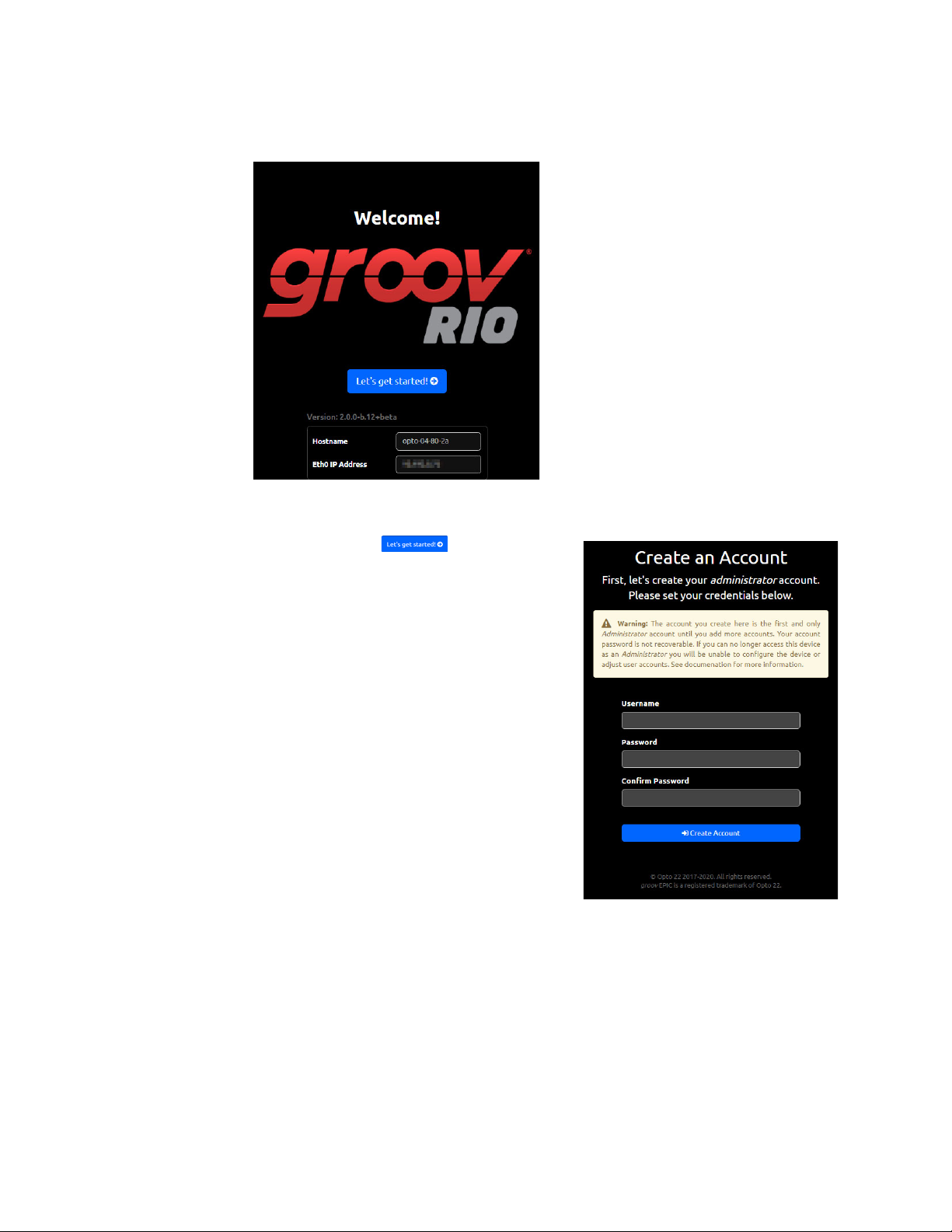
The Welcome! screen appears on the browser window.
If, after a few minutes, you do not see the Welcome! screen or you can get an error from the browser,
check “Browser Reports that URL to RIO is Unreachable” on page 99.
4. Click Let’s get started! ( ). You’ll see the Create
an Account screen.
Read the information in the warning box. This first
administrator account is very important because it
provides administrator privileges over the groov RIO,
which gives you access to all the functions you need to
configure it, maintain it, and create other accounts.
It’s also important to remember the username and
password to this account. The groov RIO does not provide
a way to recover this password nor an alternate way to
access this account if you forget the password. Also,
Opto 22 cannot recover this password or provide access
to the account.
5. Type in a user ID and password for this administrator
account, then click Create Account.
It is a good idea to follow best practices regarding
passwords (for example, mixing cases and including
numbers) when you create your password. Your
password must be a minimum of 1 character and can be
a maximum of 128 characters.
16
groov RIO User’s Guide
Page 25

CHAPTER 3: INITIALIZING A GROOV RIO
6. groov Manage displays a screen with these options:
– Quick Start—The quick start provides a list of suggested configuration steps that you should
complete first to get your groov RIO up and running. You may want to choose this option if this is
the first time you configure a groov RIO. If you select this option, go to the next step.
– Configure Device—If you select this option, groov Manage displays the Home page, where you
can make any configuration changes. You may want to choose this option if you have configured a
groov RIO before or you feel confident you have all the information and understand the technology
and software installed on the RIO to complete any configuration steps. If you select this option, skip
to step 8.
7. Click Quick Start. groov Manage displays the Quick Start page.
The boxes are organized to suggest an order in which to complete the configuration. However, you do
not have to follow this order nor do a configuration task for every box. Here’s why you might want to
complete each step:
– Networking—You might want to configure or change networking settings because you want to
change the IP address or hostname that was assigned to the unit. You might want to set the IP
address manually (which would make it a static IP address) or disable a network interface.
– Accounts—You might want to create additional accounts as required by the design of your site.
– Time—You can choose between manually setting the date and time, selecting a time zone from a
list, or selecting a time server that will synchronize your unit’s date and time with that time server’s
date and time.
After you finish each configuration task, click back to return to the Quick Start page.
8. In groov Manage, click the menu button ( ), then select Info and Help.
9. In the Info and Help page, click About.
10. In the groov RIO section, note the version in the System Version field.
groov RIO User’s Guide
17
Page 26

11. Log on to opto22.com and enter the part number for your groov RIO in the Search box. Select the search
result that includes “Firmware” as part of the title; for example GRV-R7-MM1001-10 Firmware.
12. Note the firmware version number listed on the page.
– If the version number on the web page is the same as the version number you noted in step 10, you
have the latest version of firmware installed on your groov RIO. You can continue on to selecting the
functions, signal types, and features for each channel and configuring groov RIO.
– If the version number on the web page is larger than the version number you noted in step 10, you
need to update the firmware on your groov RIO. Follow the instructions in “Updating Firmware on a
groov RIO” on page 96. After you update the firmware, you can continue on to selecting the
functions, signal types, and features for each channel and configuring groov RIO.
18
groov RIO User’s Guide
Page 27

4: Navigating groov Manage
When you connect to groov RIO through a web browser on a computer, you navigate through the web
browser in much the same way you navigate through any other web application on your computer. You can
click on navigation aides like the navigation bar or links, and scroll up and down with a mouse.
UNDERSTANDING THE PAGE NAVIGATION AIDS
The diagram below identifies some of the important page navigation aids:
A
C
B
B
D
A Menu button ( ). Click or tap on this button to access a list of important pages. This button can
help you quickly jump to these pages.
B Cancel or previous page. The upper-left area of the page provides a way to cancel any changes you
might have made to fields on the current page, return to the previous page, or both.
C Save, Configure, or Done. If there are settings on the page that you can change, the upper-right area
of the page displays the word Configure. Click on Configure to open up the page where you actually
make the changes.
If this area shows the word Save, you must click on it to save any changes you made to settings on
the page. If, after saving, the processor must restart an application or service, it displays a message to
let you know.
If this area is blank, that means you can’t make any changes to this page.
D Links. When you see these arrows, it indicates that clicking or tapping on the arrow will open another
page that displays more information and provides more functions related to the item. For example,
when you click Project Management in the Node-RED page, groov Manage displays another page
with information and functions to help you manage a Node-RED project.
A
C
groov RIO User’s Guide 19
19
Page 28

LEARNING HOW INFORMATION IS ORGANIZED IN GROOV MANAGE
LEARNING HOW INFORMATION IS ORGANIZED IN groov MANAGE
At the top of the groov Manage page is a navigation bar that always remains visible as you navigate through
the screens. This navigation bar contains a menu button ( ) that gives you quick access to the most
frequently visited screens of groov Manage:
Navigation bar, with the menu button closed.
Navigation bar, with the menu button open.
• Home, the main page of groov Manage.
• I/O, the page that displays a visual representation of channels on the RIO unit.
• System, the page that displays functions to help you configure system-level settings, like network
settings, time zone settings, file manage, and the ability to restart RIO.
• Info and Help, the page that gives you access to more information about RIO, like RIO unit log files, RIO
unit information, on-board documentation, firmware versions, as well as a way to access the Quick Start
page.
• User, the page that displays the user name of the current user and the fields to change the current user’s
password.
Navigating Through groov Manage on a Computer or Mobile Device
You can navigate through groov Manage on a computer or mobile device in much the same way you navigate
through any other web application. You can Drag-and-drop—a feature commonly used on a computer to
visually and easily move files from one location to another. You can drag-and-drop files into groov RIO on any
groov Manage page with an upload button.
FINDING INFORMATION ABOUT I/O CHANNELS
To view information about and making changes to channels, you access I/O Channels page of groov Manage.
To reach that page, log into your groov RIO with a user ID that has administrator privileges and then do any of
the following:
• Click or tap on the menu button ( ), then select I/O.
• In the Home page, click or tap on I/O Channels.
20
groov RIO User’s Guide
Page 29

CHAPTER 4: NAVIGATING GROOV MANAGE
Either action displays the I/O Channels page. The page displays a table where each row is a channel.
A
B
A The grey box shows the channel number at the top, the function and signal type on the bottom.
B For each channel, this area shows the channel name (if one has been assigned) at the top and a
summary of the signal information on the bottom. The summary varies; it could be the state of a
discrete input or output, the temperature reading from an ICTD probe, or quality indication.
groov RIO User’s Guide
21
Page 30

FINDING INFORMATION ABOUT I/O CHANNELS
22
groov RIO User’s Guide
Page 31

5: Controlling Access to groov RIO
PART OF AN OVERALL SECURITY SYSTEM
When you control access to groov RIO, consider it as part of a total security system that includes other best
practices you might want to implement; for example, requiring that authorized users change their passwords
every three months or securing the control equipment in a locked cabinet with keys accessible to a limited
number of personnel.
IMPORTANT: groov Manage does not provide timeout-based logout. You must implement the important
practice of always logging out of any ID that has administrator privileges to prevent unauthorized access to RIO.
CREATING USER IDS AND CONFIGURING THEIR ACCESS
With groov Manage, you can create user IDs and limit access to RIO functionality and features. Before you
create a user ID, consider the following questions:
• How many users do you want to create?
• What functions do you want the users to access?
• How will you secure (encrypt or password-protect) the information about the users?
Choosing Access Levels for Users
The following information can help you determine what access to give a user and what level of access to give
a user for a particular service or feature:
• A unit-wide administrator can do the following:
– Create other user accounts
– Access all services running on this unit
– Change the passwords of other accounts
– Sign out any and all users currently logged into this unit
– Change unit-wide settings like network, I/O, time and date, etc.
• groov Manage—groov Manage is an administrator-level function, so if the user is a unit-wide
administrator, they have access to groov Manage. If the user is not a unit-wide administrator, they do not
have access to groov Manage.
• Node-RED—Access to Node-RED is either Editor or Off. For unit-wide administrators, Editor is the
automatic and only access level. For all other users, you can set the access level to either Editor or Off.
• PAC REST API—Access to the PAC REST APIs can be one of the following:
– Read-Write
– Read-Only
– None
groov RIO User’s Guide 23
23
Page 32

MANAGING THE SSL SECURITY FEATURES OF YOUR GROOV RIO
Creating User IDs
After you consider what types of users you want to create and what they will have access to, do the following:
1. Log into your groov RIO with a user ID that has administrator privileges.
2. Click Accounts.
3. Click Add (in the upper right corner).
4. Type in the required information and select the permissions you want that user to have.
5. Click Save (in the upper right corner).
Repeat these steps for every user account you want to create.
MANAGING THE SSL SECURITY FEATURES OF YOUR groov RIO
The SSL security features on groov RIO help you establish secure communication between RIO and web
browsers, servers, brokers, and cloud services.
Learning How SSL Works on groov RIO
If you are not familiar with SSL, you might want to spend some time reading the following OptoBlog,
Understanding SSL/TLS and HTTPS.
Each groov RIO comes with a unique certificate (called a self-signed, server SSL certificate) to enable
communication between its internal web applications (like groov Manage and Node-RED) and web browsers
on computers and mobile devices. When you connect to groov RIO through a web browser for the first time,
the browser displays a warning message that the site (in this case, your groov RIO) is untrusted. To avoid the
warning, you can install the self-signed, server SSL certificate into the certificate store of the web browser.
Afterwards, the browser will “trust” your RIO (the site) and no longer display that warning.
Creating a Self-Signed Certificate
1. Log into your groov RIO with a user ID that has administrator privileges.
2. Click Security > Server SSL > Create Certificate.
3. In the Create Certificate page, enter the information requested.
Server Name—Enter the fully qualified domain name or IP address of this groov RIO that others will use
to access it. The server name may contain letters a–z (case insensitive), digits 0–9, or a hyphen (-). No
other characters are allowed. The server name must not start with a hyphen.
Example:
If the URL that others will use to access the RIO is https://process1.acme.com, then type in
process1.acme.com
Example:
If the URL that others will use to access the RIO is https://mobilehmi.mydomain.com, then type in
mobilehmi.mydomain.com
Email—The email address of the individual in your organization requesting the certificate and who
would be responsible for responding to any inquiries about this certificate.
Department—Information to differentiate between divisions within an organization. For example,
“Engineering” or “IT”. If applicable, you can enter the DBA (doing business as) name in this field.
Organization—The legally registered name of your business. The listed organization must be the legal
registrant of the domain name in the certificate request. If you are enrolling as a small business or sole
proprietor, please enter the certificate requester’s name in this field, and the DBA (doing business as)
name in the Organizational Unit field.
24
groov RIO User’s Guide
Page 33

CHAPTER 5: CONTROLLING ACCESS TO GROOV RIO
City or Locality—Name of the city or locality where your organization is located. Please spell out the
name of the city or locality. Do not abbreviate.
State—Name of state, province, region, territory where your organization is located. Please enter the full
name. Do not abbreviate.
Country Code—The two-letter International Organization for Standardization (ISO-) format country
code for the country in which your organization is legally registered. See
http://www.digicert.com/ssl-certificate-country-codes.htm for a list of codes. For example, the code for
the United States is US.
Days until expiration—Enter the number of days before the certificate is expired and has to be
replaced. Opto 22 recommends 3560 (10 years).
RSA key size—Enter the size of the RSA key. The default size of 2048 is a generally recommended value.
Higher values will take longer to create.
4. Click Create. groov Manage immediately installs the new private key and certificate, and then restarts
groov Manage.
Your groov RIO now has new copies of the Public Certificate, Private key, and CSR, which you can download
when you need to request a CA-signed certificate.
Switching to a CA-signed Certificate
When you switch to a CA-signed certificate, consider the following:
• The cost of a certificate from a certificate authority ranges from free to $300 or more, depending on the
features and company you buy them from. Please work with your IT department before you begin this
task.
• You will send the CSR to the certificate authority of your choice. The certificate authority verifies the
identification information and signs the CSR, which then becomes a CA-signed certificate. That’s why it is
important that you enter accurate information in step 3 of “Creating a Self-Signed Certificate” on page 24.
If you have not created a self-signed certificate, do that first. See “Creating a Self-Signed Certificate” on
page 24.
1. Log into your groov RIO with a user ID that has administrator privileges.
2. Click Security > Server SSL > Download CSR.
3. Navigate to a folder where you want to store the CSR file. Make a note of the file name and path to the
folder. Click Save.
4. Go to the certificate authority (most likely a web site) and provide them with the information they
request in whatever format they request.
When filling out a form for a CA-signed certificate, keep in mind that an SSL certificate works with any
operating system. If you are asked to select an operating system, select “other” if it an option. It’s OK to
select a specific operating system, if necessary.
5. Finish the transaction with the certificate authority and receive your new SSL certificate.
6. Upload the new SSL certificate to your groov RIO:
a. Return to the View Certificate page. (See steps 1 and 2.)
b. Click Upload Certificate.
c. Click Public Certificate.
d. Navigate to the folder where you stored the new SSL certificate. Click Open. groov Manage uploads
the file and then displays the Upload Certificate page.
e. Click Private Key.
f. Navigate to the folder where you stored the private key file. Click Open. groov Manage uploads the
file and then displays the Upload Certificate page.
g. Click Upload (in the top right). groov Manage displays a message that it must restart. Click on Reload.
After groov Manage restarts, you can begin working with services that requires a CA-signed certificate.
groov RIO User’s Guide
25
Page 34

MANAGING THE SSL SECURITY FEATURES OF YOUR GROOV RIO
Uploading a Public Key Certificate
There are several reasons you might need to upload a public key certificate:
• To enable secure client/server communication (with HTTPS or TLS/SSL) between your groov RIO (acting
as client) and a PAC Control strategy or a Node-RED flow (acting as a server).
• To enable secure communications through Sparkplug.
To upload a public key certificate, you must make sure that it is stored on a computer or mobile device that
can connect to your groov RIO.
1. Log into your groov RIO with a user ID that has administrator privileges.
2. Click Security > Client SSL.
3. In the Public Certificates window, click Add/Update.
4. Navigate to the folder where you stored the certificate and select the certificate (.pem) file.
5. Click Open. groov Manage uploads the file and you’ll see it listed in the Certificates section.
If you need to upload another certificate, repeat steps 3 through 5.
Changing SSL Security Features for Sparkplug
If you are using Sparkplug with MQTT to publish data from groov RIO, you must first create and install a
CA-signed Certificate on RIO.
• For instructions on creating the certificate, see “Switching to a CA-signed Certificate” on page 25.
• For instructions on installing the certificate on the processor, see “Uploading a Public Key Certificate” on
page 26.
After you installed the certificate(s):
1. Log into your groov RIO with a user ID that has administrator privileges.
2. Click MQTT > Configuration.
3. For each MQTT Broker that you have listed on the MQTT page and for which you want to enable SSL:
a. Click the broker name to open its MQTT Broker settings window.
26
groov RIO User’s Guide
Page 35

CHAPTER 5: CONTROLLING ACCESS TO GROOV RIO
b. Move the slider to the right so that it shows green ( ). groov Manage displays a new row
below the SSL row.
c. Click Select Certificate. groov Manage displays the CA Certificate window with a list of public key
certificates installed on the processor. Select the certificate you want.
groov Manage refreshes the MQTT Broker settings window to show the name of the certificate you
chose.
d. Click OK.
4. When you are done modifying all the MQTT Brokers that you wanted to change, click Save.
If there are any errors in any of changes you made, groov Manage highlights the broker with the error in red.
Select that broker to view more information about the errors. Make any necessary changes and try saving
again.
CONFIGURING THE FIREWALL
You might be accustomed to hearing or reading about firewalls to protect corporate networks, home
networks, and even individual computers. groov RIO also contains firewall technology to protect it from
unauthorized connections and communication.
Before you configure the firewall on RIO, make sure you understand the following:
• Firewall rules and how they work.
• If you need to create a new rule, you need to know the protocol you want to select (TCP, UDP, or both)
and the port number, or range of port numbers, to which this rule will apply.
• The default firewall rules. These rules are in the firewall as part of the default factory settings.
groov RIO User’s Guide
27
Page 36

CONFIGURING THE FIREWALL
Creating a Firewall Rule
When you make changes to the RIO’s firewall, the changes take effect immediately. So, make sure you
schedule this change during a time that minimizes the impact to your system and users. If necessary, notify
your users of this change so they can plan accordingly.
To create a new rule for the firewall:
1. Log into your groov RIO with a user ID that has administrator privileges.
2. Click Security.
3. Click Firewall. The Firewall page displays the rules currently in effect and may look similar to this:
[
4. Click Add Rule. Type in information for the new rule:
– Title—This will display as a new section title, which has limited space. A title of less than 30
character fits well in the space.
– Protocol—Select which protocol this rules applies to.
– Port—Type in the port number or port number range. Specify a port range by typing in the first
port number in the range, followed by a colon, then the last number in the port range, with no
spaces between the numbers and the colon.
– eth0, wlan0, or tun0—Select which port this rule applies to by moving the slider to the right so
that it shows green ( ).
28
groov RIO User’s Guide
Page 37

CHAPTER 5: CONTROLLING ACCESS TO GROOV RIO
5. Click OK. If there are any errors in your selections groov Manage highlights the error and displays an error
message.
Fix the error or errors and then click OK.
6. Repeat the previous two steps for any additional rules you want to create.
7. Click Save. groov Manage displays a message that it is configuring the firewall.
After groov Manage finishes saving and implementing the changes, it displays the Security page.
Please note that adding or changing firewall rules (which effectively opens ports in the firewall) does not start
the listening services that may or may not be behind those ports. If you encounter problems accessing those
services, check that the services are on and listening.
Changing a Firewall Rule
When you make changes to groov RIO’s firewall, the changes take effect immediately. So, make sure you
schedule this change during a time that minimizes the impact to your system and users. If necessary, notify
your users of this change so they can plan accordingly.
To change a firewall rule:
1. Log into your groov RIO with a user ID that has administrator privileges.
groov RIO User’s Guide
29
Page 38

CONFIGURING THE FIREWALL
2. Click Security > Firewall. The Firewall page displays the rules currently in effect and may look similar to
this:
3. Click or tap on the rule you want to change.
4. Make changes.
5. Click OK. If there are any errors in your changes, groov Manage highlights the error and displays an error
message.
[
30
Fix the error or errors and then click OK.
groov RIO User’s Guide
Page 39

CHAPTER 5: CONTROLLING ACCESS TO GROOV RIO
6. Click Save. groov Manage displays a message that it is configuring the firewall. If there are any conflicts
with existing rules, groov Manage will highlight the row with the conflict and then you can change the
rule to eliminate the conflict.
After groov Manage finishes saving and implementing the changes, it displays the Security page.
Please note that adding or changing firewall rules (which effectively opens ports in the firewall) does not start
the listening services that may or may not be behind those ports. If you encounter problems accessing those
services, check that the services are on and listening.
groov RIO User’s Guide
31
Page 40

CONFIGURING THE FIREWALL
32
groov RIO User’s Guide
Page 41

6: Connecting groov RIO to a Network or Multiple Networks
The topic of networking can be complex. In this chapter, we cover the following scenarios:
• Connecting groov RIO to a local area network, either wired or wireless.
• Connecting groov RIO to a virtual private network (VPN).
Network configuration changes will require a restart of the network connections on RIO. It’s important to have
groov Find ready to help you locate your RIO on the network. If you are not familiar with groov Find,
see“Downloading and Running groov Find” on page 100. Schedule this task at a time that minimizes the
impact on your application and equipment.
If you have an IT department, work with them as you complete these steps:
1. Review your current networking requirements and practices, as well as groov RIO’s networking
capabilities and default settings. Decide whether the default network settings are sufficient for your
network or if you need to change some of the defaults. For more information, see “Reviewing RIO’s
Network Capabilities and Default Settings” on page 34.
2. If you’ll be changing the default network settings or connecting to a virtual private network with
OpenVPN, gather up and verify the information you need before you begin changing settings. See
“Collecting Network Configuration Information” on page 38.
3. Configure the appropriate network interfaces (ETH0, WLAN0) on your groov RIO with the information you
collected from the previous step. See “Configuring the Network Interfaces” on page 42.
4. If you are connecting to a virtual private network with OpenVPN, configure the OpenVPN Tunnel 0
interface as described in “Connecting to a Virtual Private Network (VPN)” on page 44.
5. Test your network connections and fine-tune your security. See “Testing the Network Connections and
Fine-Tuning Security” on page 46.
groov RIO User’s Guide 33
33
Page 42
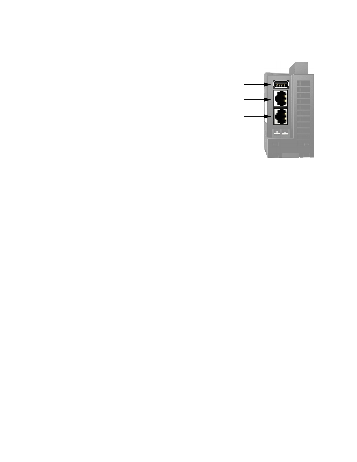
REVIEWING RIO’S NETWORK CAPABILITIES AND DEFAULT SETTINGS
REVIEWING RIO’S NETWORK CAPABILITIES AND DEFAULT SETTINGS
You can connect groov RIO to up to three different networks:
• Wired communications through either ETH0 or ETH1.
Note that you can’t connect two different networks
through these interfaces; RIO has switched Ethernet
interfaces, not independent Ethernet interfaces.
• Wireless communication, through an approved USB
WiFi adapter connected to the USB port. For a list of
approved adapters, see “Installing an Approved USB
WiFi Adapter” on page 95.
• A virtual private network (VPN), connected through
either ETH0, ETH1, or WLAN0.
WLAN0 is physically separated from ETH0/ETH1, which
means there is no communication or routing between the
wired and wireless networks.
You can configure the network interfaces to connect to several networks in a variety of combinations. For
example:
• Configure ETH0 to connect to a local control network and configure WLAN0 to connect to a local office
network.
• Configure ETH0 to connect to a local network, configure OpenVPN Tunnel 0 to connect to a virtual
private network, and leave WLAN0 alone or, for enhanced security, disable it.
• Configure ETH0 to connect to your local control network and configure WLAN0 to connect to the
Internet.
USB (WLAN0)
ETH0
ETH1
In addition, you can daisy-chain RIOs: connect several RIOs through their wired network interfaces to form a
chain. The primary advantage of daisy-chaining is that you save the expense of network routers or switches.
The primary disadvantage is similar to that of a serial network: if communication with one RIO is lost,
communication to all RIOs beyond it on the daisy-chain are also lost. If you do decide to daisy-chain RIOs, keep
in mind the following:
• When you update firmware on RIOs in the chain, you must update them one at a time.
• You cannot daisy-chain RIOs through WLAN0, the wireless network interface.
• Never form a loop or ring with a chain of RIOs. As a rule, do not connect the second interface on the last
RIO on the chain to any other device.
• You cannot daisy-chain RIOs powered through PoE. All the RIOs in the chain must be powered with a
10-32 V DC power supply.
34
groov RIO User’s Guide
Page 43

CHAPTER 6: CONNECTING GROOV RIO TO A NETWORK OR MULTIPLE NETWORKS
The following illustrations show the correct and incorrect way to daisy-chain RIOs:
CORRECT DAISY-CHAIN CONNECTIONS
Leave the 2nd interface on
Daisy-chain
connections
Connections from a network, SNAP PAC
controller, groov EPIC processor, or PC to a RIO.
INCORRECT DAISY-CHAIN CONNECTIONS
the last RIO unconnected.
Ethernet Switch
Ethernet Switch
Ethernet Switch
Understanding RIO’s Default Network Configuration
When you take it out of the box, groov RIO is ready to automatically connect to a network by plugging an
Ethernet cable into ETH0 or ETH1. This works most directly in a network that is simple (for example, a
computer and a few devices) and that has a DHCP server that manages IP addresses.
If your groov RIO will be running in this type of networking environment, review “Initializing with a Wired
Connection” on page 36. You can probably skip over the rest of the information in this chapter. However, if you
think you might need to change this configuration:
1. Review these two sections to understand two important network operations of groov RIO:
– “Initializing with a Wired Connection” on page 36
– “Keeping Networks Separate” on page 36
2. Read through “Reviewing Your Network Requirements” on page 36 (with your IT department, if you have
one) to understand all the important you choices you may have to make so that RIO can your work in
your networking environment.
3. Collect the information you need, based on the choices you made in the previous step. (See “Collecting
Network Configuration Information” on page 38.)
4. Make the changes to RIO (see “Configuring the Network Interfaces” on page 42.)
groov RIO User’s Guide
35
Page 44

REVIEWING YOUR NETWORK REQUIREMENTS
Initializing with a Wired Connection
When you initialize your RIO, you must connect it to a network through either ETH0 or ETH1, which means a
wired network connection. (For more information about initialization, see Chapter 3: Initializing a groov RIO.)
So, plan on using RIO right out of the box with a wired network connection. After you finish all the
initialization (which can include configuring the network interfaces for other types of network connections),
you’ll switch to the networking configuration you want.
If, with your new network configuration, you won’t be using some of your network interfaces, you may want
to disable them to prevent unauthorized access to your RIO. However do not disable those network interfaces
until you have verified that your new network configurations works; if you don’t test it, you may end up with
a RIO that is inaccessible (including through groov Find) and you will have to reset it to factory defaults.
To disable a network interface:
1. From the groov Manage Home page, click System > Network.
2. Click Configure.
3. For the network interface(s) you aren’ t using, click IPv4 Method, then select Disabled.
4. Click Save. groov Manage will save the changes and restart the network connections.
Keeping Networks Separate
Each network interface must be connected to a separate network. Make sure that the wireless access point
(SSID) that you select for WiFi is not on the same network as ETH0.
REVIEWING YOUR NETWORK REQUIREMENTS
In a simple network, a DHCP server assigns the following to any new device that joins the network:
• IP address
• Subnet mask
• DNS server: IP address and domain name
• Gateway IP address
With simple applications and networks, having the DHCP server manage these assignments is usually
sufficient. Out of the box, groov RIO is designed to work with this type of network. If your application and
network fall into this category, review “Choosing between Automatic and Manual Connections” (below).
However, for certain applications or in some complex networking environments, you may want groov RIO to
override or ignore the information it receives from the DHCP server.
• Example 1—Your IT department may want to assign your RIO a static IP address and subnet mask.
• Example 2—Your IT department may want to assign a specific gateway address, or DNS server IP
address and domain name to a network interface (ETH0, WLAN0, or OpenVPN Tunnel 0).
• Example 3—Your IT department may want to route traffic leaving groov RIO through a specific path.
These examples illustrate why it is important to work with your IT department (if you have one) before
connecting your groov RIO to a complex network. Review the information in the rest of this section with your
IT department. As you review the information, you’ll be collecting information that you’ll need when it’s time
to configure the network interfaces. Instructions on what information you need to collect are in “Collecting
Network Configuration Information” on page 38.
Choosing between Automatic and Manual Connections
36
For each physical network interface on a groov RIO that you are connecting to a network, you can choose one
of two connection methods:
groov RIO User’s Guide
Page 45

CHAPTER 6: CONNECTING GROOV RIO TO A NETWORK OR MULTIPLE NETWORKS
• Automatic—The DHCP server assigns the IP address and subnet mask. Select this method if:
– Your network is simple and small with a DHCP server.
– The default network settings on groov RIO meet the needs of your network environment.
– The default network settings meet your networking requirements and you plan to add a wireless
adapter.
– The DHCP server can assign the IP address and subnet mask, but you want to be able to override the
gateway address or DNS IP address and name server.
For any of these situations, review “Collecting Information for Automatic Connections” on page 38.
• Manual—You or the IT administrator need to enter an IP address, a subnet mask, and, in the cases
described below, additional configuration information. Select this method if you or your IT department
require advanced network configurations.
Implementing Advanced Networking Requirements
For the unique cases described earlier, review the information below. Most of these options are available on all
the network interfaces (ETH0, WLAN0, and OpenVPN Tunnel 0).
• If you need to override the DNS server IP address and domain name assigned by the DHCP server, see
“Overriding the DNS Server IP Address and Domain Name Assigned by DHCP Server” (below).
• If you need to do either of the following, see “Adding DNS Servers and Specifying the Order in which DNS
Servers are Queried” (below):
– Add more DNS server IP addresses and domain names.
– Specify the order in which the DNS servers are added to the DNS resolver’s configuration.
• If you need to do either of the following, see “Adding Gateway IP Address or Overriding the Gateway IP
Address Assigned by the DHCP Server” (below).
– Add a gateway IP address or override the gateway IP address assigned by the DHCP server.
– Alter the order in which gateways are invoked. Gateway Order determines which interface's
gateway is used for off-subnet destination-based routing. The gateway associated with the active
interface with the lowest gateway order will be used as the default gateway. For more information
about this topic, see “G: Advanced Networking Configurations” on page 247.
Overriding the DNS Server IP Address and Domain Name Assigned by DHCP Server. If your
network policy is for the DHCP server to assign the IP address and subnet mask, but the IT administrator
manually assigns the domain name server (DNS), you will need the IP address and domain name of that server
when it’s time to configure groov RIO. Record this information “Table of Additional Gateway IP Addresses, DNS
IP Addresses and Name Servers, and Order” on page 40 (in the Automatic section, as DNS Server 1 Override
and DNS Domain 1 Override, under the network interface that requires this configuration) so that it is readily
available when you configure your RIO.
You can specify additional domain name servers, entering them as the second (DNS Server 2 Override with
DNS Domain 2 Override) and third (DNS Server 3 Override with DNS Domain 3 Override) entries in the table,
also in the Automatic section.
Adding DNS Servers and Specifying the Order in which DNS Servers are Queried. You can
assign up to three domain name servers to each network interface on RIO and indicate the order in which to
communicate with the servers. You can set the DNS Order of a network provisioning domain to specify the
priority that name servers and search domains are added to the DNS resolver's configuration, which has a
maximum limit of three name servers and six search domains. When a DNS request is made, the resolver
queries name servers in series in the order defined in the configuration. If a response is received with either a
successful resolution or with a reply code such as "Name not found", no other name servers are queried. If the
DNS request times out, the next name server is tried until all name servers are exhausted. Be aware that name
resolution of secondary and tertiary name servers may be slow due to the sequential nature of queries by the
DNS resolver.
groov RIO User’s Guide
37
Page 46

COLLECTING NETWORK CONFIGURATION INFORMATION
For each network interface that requires this configuration, make a note of the DNS server IP addresses and
domain names in the Automatic section (for network interfaces where you selected Automatic connection) or
the Manual section (for network interfaces where you selected Manual connection) of “Table of Additional
Gateway IP Addresses, DNS IP Addresses and Name Servers, and Order” . The DNS Order is per network
interface, with 1 being the highest priority (the network interface queried first).
Adding Gateway IP Address or Overriding the Gateway IP Address Assigned by the DHCP
Server.
information in “Redirecting Traffic Initiated by an Incoming Connection Request” on page 247 to understand
how groov RIO manages gateway assignments and prioritizes their use.
For each network interface that requires this configuration, make a note of the gateway IP address in the
Automatic section (for network interfaces where you selected Automatic connection) or the Manual section
(for network interfaces where you selected Manual connection) of “Table of Additional Gateway IP Addresses,
DNS IP Addresses and Name Servers, and Order” . The Gateway Order is per network interface, with 1 being
the highest priority (the network interface queried first).
If your network policy requires the assignment of a specific gateway IP address, review the
COLLECTING NETWORK CONFIGURATION INFORMATION
If you will be changing the default network setting or connecting to a virtual private network (VPN), you will
want to collect some configuration information from your IT administrator. To help you organize this
information and make it quicker to do the configuration, print the following tables and fill them out as you
collect the information.
• “Tables for IP Address, Subnet Mask, and Additional Wireless Settings” on page 39
• “Table of Additional Gateway IP Addresses, DNS IP Addresses and Name Servers, and Order” on page 40
Save this information in a secure location that you can quickly access and refer to this information when you
start following the instructions in “Configuring the Network Interfaces” on page 42.
Collecting Information for Automatic Connections
By default, groov RIO connects to networks automatically. If this method adequately meets the needs of your
application, then:
• For wired communications, there is no additional information that you need to collect. Fill in the table
(“Tables for IP Address, Subnet Mask, and Additional Wireless Settings” ) with “Automatic” in the ETH0
column to remind you that you do not need this information.
• For wireless communications, fill in the IP address and Subnet mask rows of the table with “Automatic”;
you don’t need to manually specify an IP address and Subnet mask with Automatic. However, you do
need to collect the following information:
– SSID—A text string from 1 to 32 characters that uniquely identifies the wireless network. This
should be the name of the wireless network access point you want groov RIO to join.
– Encryption—The type of encryption to secure the packets:
– None—Do not encrypt the packets.
– WEP—A wireless security protocol that is not secure and has been deprecated by the Institute
of Electrical and Electronics Engineers (IEEE). Do not select WEP for new installations unless it is
the only option available.Instead, select WPA or WPA2.
– WPA—Encrypt the packets with TKIP encryption (RC4) and an 8 to 63 digit ASCII or 64 digit
hexadecimal key.
– WPA2—Encrypt the packets with CCMP encryption (AES) and an 8 to 63 digit ASCII or 64 digit
hexadecimal key.
38
groov RIO User’s Guide
Page 47

CHAPTER 6: CONNECTING GROOV RIO TO A NETWORK OR MULTIPLE NETWORKS
– Key Type—Select one of the following:
– Passphrase (ASCII)—This is the typical key type for WPA.
– PSK (HEX)—This is the typical key type for WEP.
– Key—The password groov RIO must provide when it tries to join the wireless network.
TABLES FOR IP ADDRESS, SUBNET MASK, AND ADDITIONAL WIRELESS SETTINGS
WIRED WIRELESS
ETH0 WLAN0
IP address IP address
Subnet mask Subnet mask
SSID
Encryption type
Key type
Key Do not write down.
None
WEP WPA WPA2
Passphrase (ASCII)
PSK (HEX)
Collecting Information for Manual Connections
If you want to specify network configuration information manually, work with your IT department (if
available), and note the following information in the “Tables for IP Address, Subnet Mask, and Additional
Wireless Settings” on page 39:
• IP Address and Subnet Mask—These two pieces of information work together to create a unique
network address. It’s very important that you create a unique network address by assigning each network
interface a different IP address and subnet mask. While the IP address must be different than any other
device on the same network, the subnet mask must be the same as all other devices on the same network.
For example:
– All the devices on network A are assigned a subnet mask of 255.255.0.0.
– All the devices on network B are assigned a subnet mask of 255.0.0.0.
If you connect the processor to network A, make sure to specify 255.255.0.0 as the subnet mask.
• For wireless communications, in addition to the IP address and subnet mask, you need to collect the
SSID, Encryption, Key Type, and Key, as described “Collecting Information for Automatic Connections”
on page 38.
If you are also configuring the network interfaces for the complex scenarios described in “Implementing
Advanced Networking Requirements” on page 37, that section described what information to collect and
where to store in “Table of Additional Gateway IP Addresses, DNS IP Addresses and Name Servers, and Order”
on the next page.
groov RIO User’s Guide
39
Page 48

COLLECTING NETWORK CONFIGURATION INFORMATION
TABLE OF ADDITIONAL GATEWAY IP ADDRESSES, DNS IP ADDRESSES AND NAME SERVERS, AND
ORDER
Setting ETH0 WLAN0 OpenVPN Tunnel 0
Gateway Override
DNS Server 1 Override
DNS Server 2 Override
DNS Server 3 Override
DNS Domain 1 Override
DNS Domain 2 Override
Automatic
DNS Domain 3 Override
Gateway Order
DNS Order
Gateway Address N/A
DNS Server 1
DNS Server 2
DNS Server 3
DNS Domain 1
Manual
DNS Domain 2
DNS Domain 3
Gateway Order
DNS Order
N/A
Collecting Network Configuration Information for OpenVPN Connection
There are many resources available online to help you learn about and set up a virtual private network (VPN)
with OpenVPN technology. This section assumes you have a functioning OpenVPN server. groov RIO works as
an OpenVPN client that connects to the OpenVPN server. (groov RIO cannot be set up as an OpenVPN server.)
You’ll need the OpenVPN server administrator to provide you with the following:
• A username and password to login to the OpenVPN server.
• If necessary, a username and password for proxy connections.
• Depending on the security and authentication configuration of the OpenVPN server, you may need some
or all of these files or information:
– A public key, also known as a certificate, which is typically available as a file that ends in .crt.
– A private key that is created specifically for your groov RIO. It is typically available as a file that ends in
.key.
– A Certificate Authority (CA) certificate and key, which helps verify the public and private keys. These
are also typically provided in files, with the certificate file that ends in .crt and the key file that
ends in .key.
– An OpenVPN static key, if required. Not all sites implement OpenVPN static keys. This key is typically
stored in a file called static.key.
• The following server information:
– Protocol–The communications protocol used by the OpenVPN server.
– OpenVPN server hostname and port number–The hostname is usually a fully-qualified domain
name (for example, vpnserver.example.com) or it could be an IP address.
– Encryption Cipher–The encryption cipher used by the OpenVPN server.
40
groov RIO User’s Guide
Page 49

CHAPTER 6: CONNECTING GROOV RIO TO A NETWORK OR MULTIPLE NETWORKS
– LZO Compression–If the OpenVPN server uses LZO compression, then you will need to enable it
on your groov RIO.
Some of this information can be provided in a configuration file, which you can then upload into your
groov RIO. Uploading a configuration file could make configuring the processor easier and you will be less
likely to introduce typing errors. When you receive the configuration file, review it to make sure it has the
following information (and in the format indicated), as appropriate for your OpenVPN server’s security and
authentication configuration:
• Certificate Authority (CA)—The CA section should be surrounded by <ca> and </ca> tags. Inside those
tags, the certificate text should be surrounded by <cert> and </cert> tags.
• Private and Public Key—The key text should be surrounded by
• Open VPN static key—The key text should be surrounded by
<key> and </key> tags.
<tls-auth> and </tls-auth> tags.
If it doesn’t contain this information, you can edit the file and add it, making sure it is surrounded by the tags
described previously.
If the administrator can’t provide a configuration file, print the following table to collect the above
information, save it in a secure place, and have it handy when you follow the instructions in “Connecting to a
Virtual Private Network (VPN)” on page 44.
TABLE OF OpenVPN SETTINGS
Information Value
Protocol udp tcp-client
OpenVPN Server Host Name __________________________________________________________
OpenVPN Server Port Number _______________
Remote Public Certificate Path
and File Name __________________________________________________________
User Name ___________________________________
Password Do not write down.
Proxy User Name ___________________________________
Proxy Password Do not write down.
Encryption Cipher none ________________
LZO Compress yes no
groov RIO User’s Guide
41
Page 50

CONFIGURING THE NETWORK INTERFACES
CONFIGURING THE NETWORK INTERFACES
1. Log into groov RIO with a user ID that has administrator
privileges.
2. Click System > Network. groov Manage displays the
Network status page.
The Network status page shows you the current network
configuration, and provides access to the Network
configuration page, as well as diagnostic tools.
In the example to the right, RIO is connected to a
network through a cable plugged into ETH0. There is no
WiFi connection through WLAN0, and no connection to
a virtual private network. The values listed in the
Network Options section were assigned by the local
DHCP server.
3. Click Configure. groov Manage displays the Network
configuration page. The example to the right shows the
default settings.
Ethernet 0 shows the current settings for ETH0. Wi-Fi
shows the current settings for WLAN0.
OpenVPN Tunnel 0 shows the current settings for a
virtual private network.
– To configure ETH0 for wired communications, see
“Configuring ETH0” on page 42.
– To configure WLAN0 for wireless communications,
see “Configuring WLAN0” on page 43.
When you are done with all the configurations, go to
“Saving the Configuration” on page 44.
42
Configuring ETH0
You’ll want to have the information you collected when you read through “Collecting Network Configuration
Information” on page 38 available as you follow these steps:
1. From the Network configuration page, click
the IPv4 Method currently assigned (the text
in green) to ETH0. groov Manage displays the
IPv4 Method window (see right).
2. Click the connection method you want. If
you choose Disable, skip to step 5.
3. If you selected Automatic and you don’t
want to override the DHCP server settings for gateway, DNS address, and DNS name server, skip to step 5.
Otherwise, now is when you enter those override values from “Table of Additional Gateway IP Addresses,
DNS IP Addresses and Name Servers, and Order” on page 40.
groov RIO User’s Guide
Page 51

CHAPTER 6: CONNECTING GROOV RIO TO A NETWORK OR MULTIPLE NETWORKS
4. If you selected Manual, the Network configuration page
changes to display additional fields. You’ll want to refer to
the values you entered in “Table of Additional Gateway IP
Addresses, DNS IP Addresses and Name Servers, and
Order” to fill out these fields:
– IP Address
– Subnet Mask
– Gateway Address
– DNS Server 1 and DNS Domain 1
These two fields must be specified as a set. If you
need to enter more than one set, groov Manage
displays fields to enter a second and third set after you enter the previous set.
– Gateway Order
– DNS Order
5. Choose from the following:
– If you need to configure WLAN0 for wireless communications, go to “Configuring WLAN0” on
page 43.
– If you are done configuring the physical network interfaces, go to “Saving the Configuration” on
page 44.
Configuring WLAN0
1. From the Network configuration page, click the IPv4 Method in the Wi-Fi section and select the
connection method you want. groov Manage updates the Network configuration page as shown below
(automatic on the left, manual on the right):
2. Enter the information you collected in “Collecting Network Configuration Information” on page 38.
3. Choose from the following:
– If you need to configure a network interface for wired communication, see “Configuring ETH0” on
page 42.
– If you are done configuring the network interfaces, go to “Saving the Configuration” on page 44.
groov RIO User’s Guide
43
Page 52

SAVING THE CONFIGURATION
SAVING THE CONFIGURATION
In the Network configuration page, click Save. groov Manage displays a message that it will restart the network
connections.
After the network connections are restarted, if groov Manage doesn’t reappear and you can’t access your RIO
through any of the network connections you configured, start up groov Find to help you locate your RIO (see
“Downloading and Running groov Find” on page 100).
After you reconnect to your RIO, you can test the network connections and fine-tune your security settings. If
you need to set up a virtual private network (VPN), see “Connecting to a Virtual Private Network (VPN)” on
page 44.
CONNECTING TO A VIRTUAL PRIVATE NETWORK (VPN)
Before you begin:
• Make sure you’ve configured at least one physical network interface (see “Configuring the Network
Interfaces” on page 42) and that it’s functioning.
• Check that you have all the information you collected when you reviewed “Collecting Network
Configuration Information for OpenVPN Connection” on page 40.
• Verify that the OpenVPN server is reachable.
Let’s begin:
1. From a browser, connect to groov RIO and log into groov Manage with a user ID that has administrator
privileges.
2. If you will be entering the configuration manually (without a configuration file as described in “Collecting
Network Configuration Information for OpenVPN Connection” on page 40), upload the public key.
a. From the groov Manage Home page, click Security > Client SSL.
b. Click Add/Update.
c. Navigate to the folder where you stored the public key (.crt) file.
d. Select the key, then click Open.
3. Click Back > Home to return to the groov Manage Home page, then click System > Network.
44
groov RIO User’s Guide
Page 53

CHAPTER 6: CONNECTING GROOV RIO TO A NETWORK OR MULTIPLE NETWORKS
4. Click Configure.
5. In the OpenVPN Tunnel 0 section, click IPv4 Method and select Automatic (DHCP).
6. Enter the configuration information you collected when you reviewed “Collecting Network Configuration
Information for OpenVPN Connection” on page 40.
– If your VPN information is in a client configuration file, click Upload Configuration File. Navigate to
the folder where you stored the configuration file, select it, then click Open. Click Set User
Credentials to enter the OpenVPN server user name and password. If necessary, click Set Proxy
Credentials to enter the proxy credentials. Go to step 7.
– If you need to enter the configuration information manually, slide the User Configuration Wizard
switch to the right, until it turns green.
a. Click Protocol to select the protocol used by your
OpenVPN server.
b. Enter the IP address or full domain name of the
OpenVPN server in the Remote Host field
c. To enter the port number, click in the space
between the - and + sign. Type in the port
number.
d. Click Select Certificate and select the certificate
you uploaded in step 2 on page 44.
e. In the Username and Password fields, type in the
OpenVPN server username and password. (Not
the proxy username and password.)
f. Click Encryption Cipher and select the cipher
used by your OpenVPN server from the list.
g. If the OpenVPN server users LZO compression,
slide the LZO Compress switch to the right, until it
turns green.
h. If you need to modify the Gateway and DNS order, click on those numbers and change them.
7. Click Save. If groov Manage reports any errors, fix those errors and click Save. Otherwise, groov Manage
displays a message that it will restart the network connections.
groov RIO User’s Guide
45
Page 54

TESTING THE NETWORK CONNECTIONS AND FINE-TUNING SECURITY
TESTING THE NETWORK CONNECTIONS AND FINE-TUNING SECURITY
To test the network connections, do one of the following:
• If you switched to Automatic, wait a few seconds for RIO to receive an IP address from the DHCP server.
The logon page will refresh and display the IP address after it receives it.
• If you switched to Manual, verify that the IP address works by trying to connect to RIO from a web
browser. Or, from a Windows computer that’s connected to the same network, you can try the ping
command in a command prompt window.
If you encounter any issues with ETH0, and WLAN0, see “Troubleshooting” on page 99 for topics regarding
network connections. If you are troubleshooting issues with an OpenVPN connection, you can review the VPN
client logs for messages. To access the logs, from the groov Manage home page, click Info and Help > Logs >
OpenVPN Client.
For enhanced security, disable any network interfaces you aren’t using.
You may also want to update your security options and firewall settings:
• “Managing the SSL Security Features of your groov RIO” on page 24
• “Configuring the Firewall” on page 27
46
groov RIO User’s Guide
Page 55

7: Configuring a groov RIO
A user with administrator privileges is the only user that can change system features. System features provide
services like access control, device management, and time management.
SETTING AND ADJUSTING DATE, TIME, AND TIME ZONES
Setting and adjusting the date, time, and time zones can help you with more than just setting groov RIO to the
local time:
• You can change the date and time of your groov RIO to test time-sensitive features of your control
program.
• You can synchronize the clock on your groov RIO to any number of time servers from around the world.
• You can specify multiple time servers to function as backups of each other, or specify a device as a time
server.
When you turn on your groov RIO for the first time and after it establishes network connectivity, it sets the time
from a default time server. To see the default time server, from the groov Manage Home page, click System >
Time. The bottom half of the screen lists the time servers.
groov RIO User’s Guide 47
47
Page 56

SETTING AND ADJUSTING DATE, TIME, AND TIME ZONES
Setting the Date and Time Manually
There might be a few reasons why you want to set the date and time manually instead of synchronizing to
time servers:
• You want to test time-sensitive features in your control program, so you want to be able to adjust the
date and time to test those features.
• You are working in an environment (for example, a disconnected test environment) where changes in
time will not affect production or other critical applications.
Note: Changing the time manually will log out any users that are currently logged onto your groov RIO. Carefully
choose when you will change the time to minimize any adverse effect on other users.
To set the date and time manually:
1. Log into groov RIO with a user ID that has administrator authority.
2. Click System ( ), then Time ( ).
3. In the Time Servers section, turn off the Enable NTP setting by moving the slider to the left so that it
shows grey ( ).
4. Click Set NTP.
5. In the Time section, select values for Year, Month, Day, Hour, Minute, and Second.
6. Click Set Time. groov Manage displays a message while it’s setting the date and time. When it finishes, the
message disappears.
Now your date and time are set.
IMPORTANT: If you set the date and time manually, the time will not update for Daylight Savings Time (for those
areas that observe Daylight Savings Time). So, you must remember to manually update the date and time during
those events.
Setting the Date, Time, and Time Zone by Synchronizing with Time Servers
If you are not familiar with time servers, you can learn more about them through the NTP Pool Project at
www.pool.ntp.org. When you are selecting a time server, remember the following:
• It is a good idea to select a couple of time servers to serve as backups in case groov RIO cannot establish
a connection to the primary time server or if that time server becomes unavailable. The steps below
instruct you to set two additional time servers.
• If you had set your date and time manually, setting the date and time as described in this section will
overwrite your manual settings.
Note: Changing the time manually will log out any users that are currently signed into your groov RIO. Carefully
choose when you will change the time to minimize any adverse affect on other users.
To select the primary time server and a few backups:
1. Log into groov RIO with a user ID that has administrator privileges.
2. Click System ( ), then Time ( ).
3. In the Time Servers section, click Time Server 1. Enter the host name of the time server.
4. Click Time Server 2. Enter the host name of a second time server.
5. Click Time Server 3. Enter the host name of a third time server.
6. Click Set NTP. groov Manage displays a message while it’s synchronizing with the time servers. When it
finishes, the message disappears.
48
Now your date and time are set, as well as the time zone. The date and time will be updated automatically
during the switches between Standard Time and Daylight Savings Time, according to the schedule set by the
time servers.
groov RIO User’s Guide
Page 57

Setting the Time and Time Zone by Selecting a Location
If you want to set the time by selecting your location, do the following steps:
1. Log into groov RIO with a user ID that has administrator privileges.
2. Click System ( ), then Time ( ).
3. In the Time Zone section, click Region to select a general geographical area of the world.
To set the time for cities or regions in the United States of America, select America as the region. America
encompasses North, Central, and South America.
4. Click Locality to select a specific city that most closely approximates the city within the time zone you
want to set.
5. Click Set Zone. groov Manage displays a message while it’s setting the time. When it finishes, the
message disappears.
MANAGING THE USB PORT
groov RIO can work with any of the following devices inserted into the USB port:
• USB storage devices. Certain requirements must be met, as described in “Requirements for USB Storage
Devices” on page 51.
• USB-to-serial adapters. Only certain adapters are supported. You can find a list at “Connecting Serial
Devices” on page 49.
• WiFi adapters. Only certain adapters are supported. For a list, see “Installing an Approved USB WiFi
Adapter” on page 55.
CHAPTER 7: CONFIGURING A GROOV RIO
If you do not plan on attaching any USB devices, it would be a good security practice to leave the USB port
disabled. Disabling the USB port prevents any unauthorized access to RIO through the port. By default, the
port is disabled, so if you plan on attaching any of the devices listed above, you need to enable the USB port. :
1. Log into groov RIO with a user ID that has administrator privileges.
2. Click System > USB.
3. Click the Enable USB slider so that it turns green.
4. Click Save. groov Manage returns you to the System page. Now you can:
– Attach a USB storage device (see “Attaching and Detaching a USB Storage Device” on page 51).
– Connect a serial device(s) (see “Connecting Serial Devices” on page 49).
– Attach a WiFi adapter (see “Installing an Approved USB WiFi Adapter” on page 55).
CONNECTING SERIAL DEVICES
You can connect serial devices to groov RIO by inserting a USB-to-serial adapter into the USB port. Before you
attach the adapter, make sure you enabled USB as described in “Managing The USB Port” on page 49.
Note: Only Node-RED flows can access serial devices connected through a USB-to-serial adapter.
groov RIO User’s Guide
49
Page 58

CONNECTING SERIAL DEVICES
The following table lists USB-to-serial adapters supported by groov RIO.
Device
Manufacturer
B&B Electronics
Gearmo
USOPTL4 (isolated RS-485)
USPTL4 (non-isolated RS-485)
USO9ML2 (isolated RS-232)
GM-482422 (non-isolated RS-485/RS-422)
GM-FTD1-A12 (non-isolated RS-232)
SERIAL-B (non-isolated RS-232)
Model
You can expand the number of serial devices you can connect to groov RIO by installing a USB hub to the USB
port. When you do this, it’s important to keep track of the device names and port numbers that groov RIO
assigns to the USB-to-serial adapter that you plug into each USB port on the hub (see “Understanding How
groov RIO Assigns Port Numbers and Device Names When Using a Hub” on page 50). One way to do this is:
1. Go to the Serial Devices page in groov Manage (Home > System > Serial Devices).
2. Insert an adapter into a port. groov Manage will detect the adapter, assign it a device name and port
number, then refresh the page to show the information.
3. Make note of the device name and port number so that you have it handy as you develop Node-RED
flows.
If you move a serial device from one USB port of the USB hub to another port on the hub, groov RIO assigns it
a new port number, and possibly a new device name. These changes might require changes to your
Node-RED flows.
Before you start connecting an adapter of USB hub to your RIO, see “Managing The USB Port” on page 49.
Device Name and Port Number
groov RIO assigns /dev/ttySer0 as the device name and 0 as the port number to the USB-to-serial adapter you
plug into the USB port. You use the device name and port number in your Node-RED flow to access the serial
device.
Understanding How groov RIO Assigns Port Numbers and Device Names When Using a Hub
If you connect a USB hub to the USB port, groov RIO includes a suffix to the device name and port number to
identify the port number on the USB hub. For example, if you connect a 4-port USB hub to the USB port, then
groov RIO assigns device names and port numbers as follows:
If a USB-to-serial adapter is plugged into port x of
the USB hub...
1 /dev/ttySer0.1 0.1
2 /dev/ttySer0.2 0.2
3 /dev/ttySer0.3 0.3
4 /dev/ttySer0.4 0.4
groov RIO assigns it a
device name of...
and a port
number of...
IMPORTANT: If you move the adapter from one USB port on the USB hub to another USB port, groov RIO will
assign a new port number and device name to the adapter. Any Node-RED flow that references the old port number
and device name will need to be modified to refer to the new port number and device name.
Finding Device Names and Port Numbers
50
You can find device names and port numbers through groov Manage.
1. Log into your groov RIO with a user ID that has administrator privileges.
groov RIO User’s Guide
Page 59

2. Click the menu button ( ), then click System.
3. Click Serial Devices. The Serial Devices page shows the device names and port numbers for any
USB-to-serial adapter plugged into the USB port.
ATTACHING AND DETACHING A USB STORAGE DEVICE
You can attach a USB storage device to the USB port on groov RIO, then use groov Manage to copy files to and
from its internal storage. Adding a USB storage device can also increase the amount of storage available for file
activities like data logging.
Important: You should store any critical files in the unit's internal storage. Internal storage utilizes a power-fail safe
file system that prevents data, file and file system corruption in the event that power is removed. USB storage devices
do not utilize a power-fail safe file system.
Requirements for USB Storage Devices
groov RIO supports reading and writing to USB storage devices formatted in either FAT or FAT32 file systems.
This means that groov RIO can not access partitions larger than 32 GB. If you want to read and write to a USB
storage device that is larger than 32 GB, you must format (with a computer) that USB storage device with
multiple FAT32 partitions. groov RIO will be able to read and write to all of the partitions on a properly
formatted USB storage device.
CHAPTER 7: CONFIGURING A GROOV RIO
Understanding How groov RIO Handles USB Storage Devices
In addition to the disabling the USB port (see “Managing The USB Port” on page 49), groov RIO provides another
setting that helps manage security issues when dealing with USB storage devices: Automount. When this
setting and Enable USB are enabled, when you attach a USB storage device, groov Manage has immediate
access to its content. If you disable Automount (but leave Enable USB enabled), you will have to go through
some extra steps to give groov Manage access to the content of a storage device.
Reviewing Security Issues with USB Storage Devices
If you do attach a USB storage device, keep the following points in mind:
• Because there is no mechanism to physically secure (or lock) the USB storage device to groov RIO, it can
be removed by anyone that has access to the unit. It’s important to apply important security practices,
like keeping the unit secured under lock and key and providing the key to only trusted individuals.
• To prevent someone from inserting an unauthorized USB storage device that could contain malicious
software, the Enable USB setting is disabled by default. Carefully consider the security risks before
enabling this setting for an extended period of time.
Disabling Access to USB Storage Devices
If you do not plan on using USB storage devices, it would be a good security practice to disable the ability to
access USB storage devices. You can still use the USB port for other devices, like supported USB-to-serial
adapters or WiFi adapters.
1. Log into your groov RIO with a user ID that has administrator privileges.
2. From the groov Manage Home page, click System > USB.
3. If you have a USB storage device plugged into groov RIO, unmount it.
a. Click USB Files.
groov RIO User’s Guide
51
Page 60

ATTACHING AND DETACHING A USB STORAGE DEVICE
b. Click Safely Remove. groov Manage displays the following message; click OK to continue:
c. When groov Manage successfully unmounts the storage device, it displays the following message.
Click Close to continue.
4. Click the Automount slider so that it turns gray ( ).
5. Click Save. groov Manage displays the System page.
groov Manage no longer has automatic access to the contents of a USB storage device inserted into the
USB port. However, as long as Enable USB is enabled, it can work with USB-to-serial adapters and WiFi
adapters.
Attaching a USB Storage Device
Before you attach a USB storage device, makes you understand:
• “Requirements for USB Storage Devices” on page 51
• “Reviewing Security Issues with USB Storage Devices” on page 51
Also, make sure you have Enable USB (see“Managing The USB Port” on page 49) and Automount (see
“Understanding How groov RIO Handles USB Storage Devices” on page 51) enabled.
52
groov RIO User’s Guide
Page 61

CHAPTER 7: CONFIGURING A GROOV RIO
Insert the USB storage device into the USB port. To verify that groov Manage has access to the USB storage
device, from the groov Manage Home page, click System > Files. groov Manage displays the Files page.
groov Manage lists the USB storage device in a section called USB Drive, typically followed by a number:
You can now copy, move, and download files (see “Copying, Moving, or Downloading a File on a USB Storage
Device” on page 54).
Detaching a USB Storage Device
Before you detach a USB storage device, evaluate the consequences; for example, would it cause an
interruption to your data logging process? After evaluating the consequences and taking measures to
mitigate those consequences, unmount the device and then remove it.
1. Log into your groov RIO with a user ID that has administrator privileges.
2. From the groov Manage Home page, click System > USB, then USB Files.
3. Click Safely Remove.
If groov Manage detects that a file on the USB storage device is still being used by a service, it will not
proceed. One likely service that might be using the storage device is a Node-RED flow that is logging
data to the storage device. Check any services that might be using the storage device.
Otherwise, groov Manage displays the following message, which reminds you that if you want to
reconnect the storage device in the future, you will have to physically reinsert it. Click OK to continue:
groov RIO User’s Guide
53
Page 62
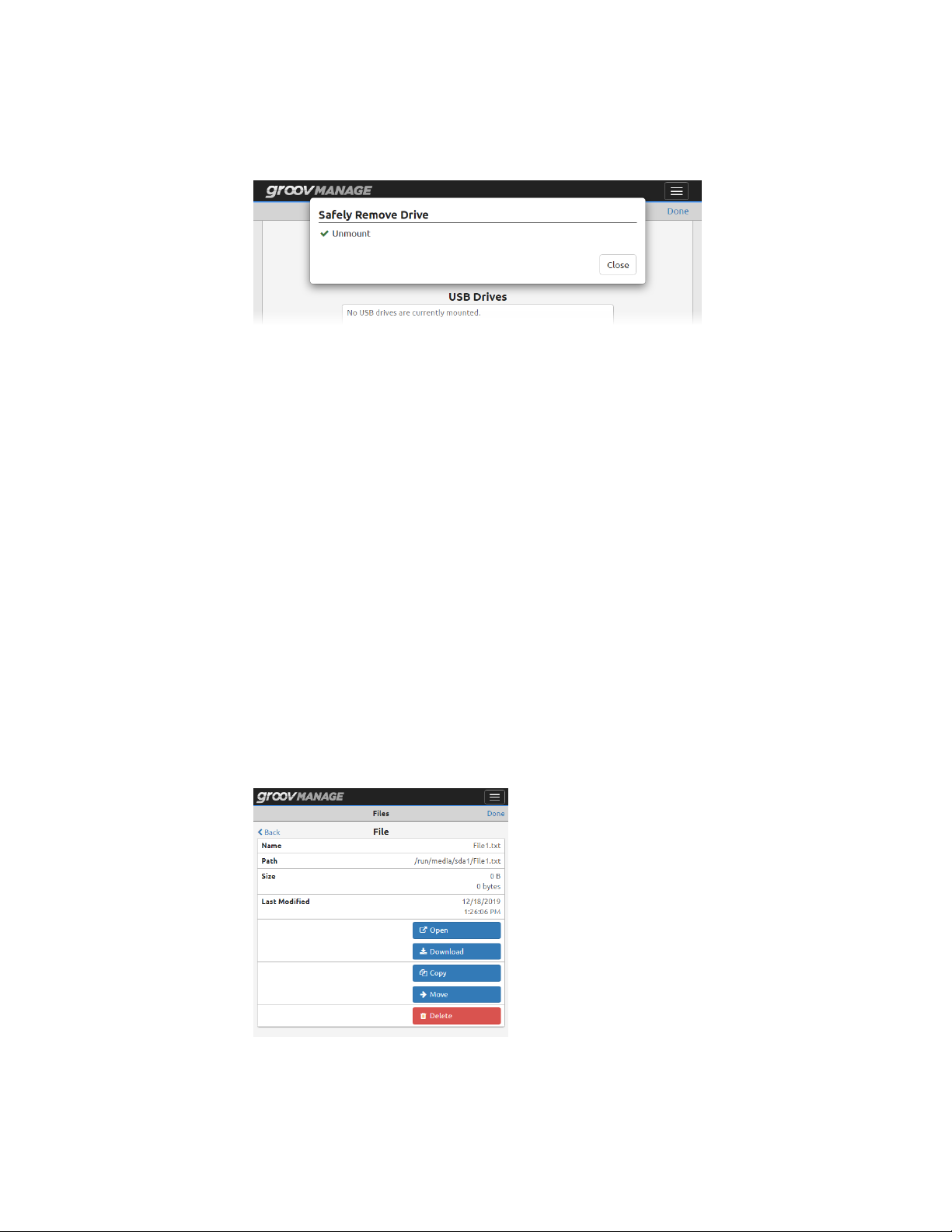
ATTACHING AND DETACHING A USB STORAGE DEVICE
When groov Manage successfully unmounts the storage device, it displays the following message. Click
Close to continue.
4. Click Done in the Files page.
5. Physically remove the USB storage device from the USB port.
6. Verify that the device no longer shows up in groov Manage.
If you do not plan on attaching USB storage devices for an extended amount of time, disable Automount to
prevent groov Manage from automatically accessing content on any storage device inserted into the USB port
(see “Reviewing Security Issues with USB Storage Devices” on page 51).
Copying, Moving, or Downloading a File on a USB Storage Device
Before you begin, make sure you have properly mounted the USB storage device as described in “Attaching a
USB Storage Device” on page 52.
• Copy and move means to transfer a file from the USB storage device to groov RIO’s internal storage.
• Download means to transfer a file from the USB storage device to you computer or mobile device.
These instructions describe how to copy, move, or download one file at a time.
1. Log into your groov RIO with a user ID that has administrator privileges.
2. From the groov Manage Home page, click System > USB, then USB Files.
3. Click on Partition 1, or, if you have multiple partitions on the USB storage device, scroll to the correct
partition and click the partition name.
4. In the Dir Listing section, navigate to the folder that has the file you want to copy, move, or download.
5. Click on the file name. groov Manage displays a list of all the actions you can take on the file:
54
– To copy a file to RIO’s internal storage, click Copy.
– To move a file to RIO’s internal storage, click Move.
groov RIO User’s Guide
Page 63

– To download a file to the computer or mobile device, click Download.
6. Click Back (top left).
– If you need to copy, move, or download another file, repeat step 4 and 5.
– If you are done copying, moving, or downloading files, click Done (top right corner). groov Manage
returns you to the USB page.
INSTALLING AN APPROVED USB WIFI ADAPTER
If you want to connect your groov RIO to a wireless network, Opto 22 recommends that you purchase and
install one of the following USB WiFi adapters, which Opto 22 has tested and verified works with groov RIO.
Unverified WiFi adapters should not be used.
Device Manufacturer Model
Linksys AE6000
TP-Link Archer T1U
Sabrent AC600
Collect the following information before starting:
• SSID of the wireless network.
• Encryption method required to access the wireless network.
CHAPTER 7: CONFIGURING A GROOV RIO
If you are manually assigning an IP address, make sure you also have the IP address and subnet mask you want
to assign to the unit.
Also, make sure you have enabled the USB port (see “Managing The USB Port” on page 49).
1. Log into your groov RIO with a user ID that has administrator privileges.
2. Insert the WiFi adapter into the USB connector on the bottom of the unit.
Note: If you have a USB storage device inserted into the port, make sure you remove it according to the
instructions in “Detaching a USB Storage Device” on page 53.
Bottom View
USB port
3. In groov Manage, go to the Network page (Home > System > Network). If the Wi-Fi section of the
Network page now has a MAC Address, then groov RIO is communicating with the WiFi adapter.
groov RIO User’s Guide
55
Page 64
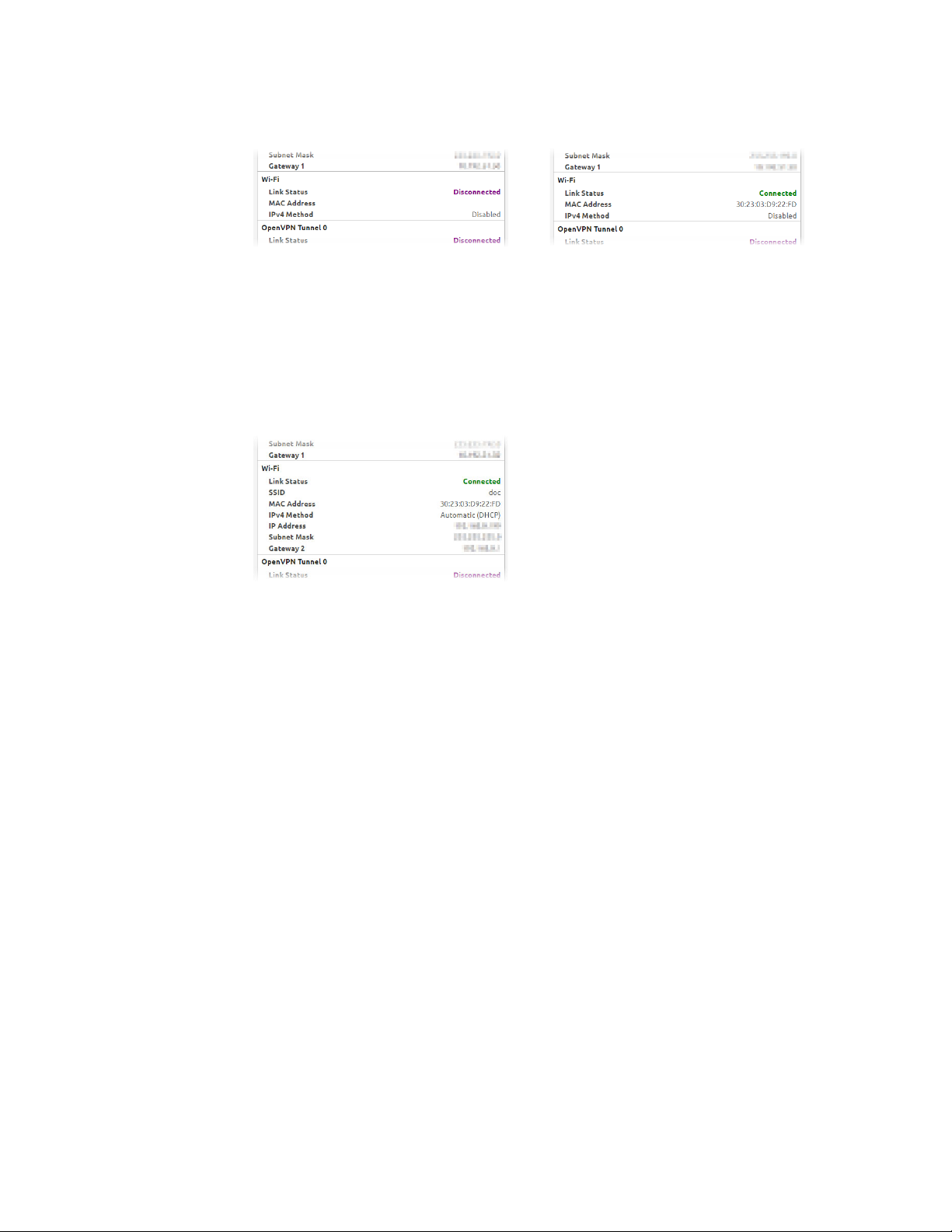
ENABLING Node-RED
No WiFi adapter inserted; no MAC address
Note, however, WiFi is disabled. The next step is to enable WiFi.
4. Click Configure (top right corner of the Network page).
5. In the Wi-Fi section, click Disabled.
6. In the IPv4 Method window, click the connection method you want: Automatic (DHCP) or Manual.
7. Enter the information you collected.
8. Click Save. Read the message that groov Manage displays and click OK. After groov Manage verifies the
information and saves the configuration, it displays the network page.
WiFi adapter installed; MAC address available
groov RIO is now connected to your wireless network.
ENABLING Node-RED
Node-RED is an open-source, multi-platform software program, where you connect (wire) together devices,
databases, cloud applications, and APIs (application programming interfaces) to create simple logic flows to
accomplish specific goals. It is pre-installed on your groov RIO; you do not have to download and install it on a
computer or embedded device. You just have to enable it, then start creating Node-RED flows. This tight
integration also means that some RIO functions, like backup, apply to your Node-RED projects.
By default, Node-RED is disabled. To enable it:
1. Log into your groov RIO with a user ID that has system administrator privileges.
2. In the groov Manage Home page, click Node-RED.
3. Click Enable. After the Status field says Running, wait a few seconds before opening the Node-RED Editor.
UPLOADING FILES TO RIO’S INTERNAL FILE SYSTEM OR USB STORAGE DEVICE
groov RIO identifies files that you upload as “user files”. You can store files in:
• The “secured area” of the internal file system, where only services with authentication (for example, a user
name and password, or an API key) over a secure protocol (HTTPS) can access the files.
• A USB storage device attached to the USB port of your RIO. Before you attach a USB storage device to the
USB port, review “Managing The USB Port” on page 49 to make sure groov Manage can access the
storage device.
56
Note that when you backup your system:
groov RIO User’s Guide
Page 65

CHAPTER 7: CONFIGURING A GROOV RIO
• Only the first 10 MB of files that you uploaded are included in the backup file.
• The files stored on the USB storage device are not included in the backup file.
When groov Manage performs a backup, it lists all the files it included into the backup file in the groov Manage
log file. You can check the log file to determine which other files you need backup by other means. (See
“Backing up Your groov RIO Settings” on page 91.)
1. Log into your groov RIO with a user ID that has administrator privileges.
2. Click System > Files. groov Manage displays the Files page.
If you had correctly mounted a USB storage device, it would appear in the USB Drives section, like this:
3. Upload a file.
To the internal file system, click Secured Files > Upload File.
To the USB storage device, click the name of the partition where you want to store the file, then click
Upload File.
a. Navigate to the folder that contains the file you want to upload and select that file.
b. Click Open. groov Manage uploads the file and then refreshes the Dir Listing section to list the file
you just uploaded.
c. If you need to upload another file, click Upload File and repeats steps a and b. For USB storage
devices, if you need to upload another file to another partition, click Back, select the other partition,
click Upload File and then repeats steps a and b.
When you are done uploading files, click Done.
groov RIO User’s Guide
57
Page 66

UPLOADING FILES TO RIO’S INTERNAL FILE SYSTEM OR USB STORAGE DEVICE
58
groov RIO User’s Guide
Page 67

8: Configuring I/O
SELECTING FUNCTIONS, SIGNALS, AND FEATURES
Before you can configure your I/O, you need to know which channel is going to serve which function and
signal, plus select which features (if available) you need:
• Function: Input or output.
• Signal: Analog or discrete.
• Feature: On State, Off State, Linearization, etc. for those signals that offer features. (For a complete list of
features, see Appendix A: Specifications.)
Note that for CODESYS applications, only a limited set of features are available. The instructions will indicate
which features are available for CODESYS applications.
If you have not determined this yet, here are a couple of options to help you select the right combination:
• RIO Explorer— An Opto 22 web app that can help you select a combination of functions, signal types,
and features, and make sure you select channels that can support your choices. When you finish with the
RIO Explorer, you can save a wiring diagram, which will come in handy when it’s time to wire up your
devices. Another way to you can use the wiring diagram is to annotate it with specification information
like ranges and scaling for analog inputs, or feature selections for discrete inputs. To learn how to use the
RIO Explorer, see Appendix C: groov RIO Explorer.
• Reviewing spec tables, feature tables, and wiring diagrams—Review the information in Appendix
A: Specifications and Appendix B: Wiring Diagrams as you follow these steps:
a. Review the features table to select which function, signal type, and, if applicable, which feature you
want for each channel. If you are working with CODESYS Development System, check the table on
page 68 for the list of features supported in that environment. You might find it helpful to note your
selections in a table like the one on the following page:
groov RIO User’s Guide 59
59
Page 68

SELECTING A METHOD FOR CONFIGURING I/O
Channel 0
Channel 1
Channel 2
Channel 3
Channel 4
Channel 5
Channel 6
Channel 7
Channel 8
Channel 9
Function
(Input or Output)
b. For each channel, check the corresponding section of the specification table and verify that you’ve
correctly selected everything. For example, if you selected a discrete input with a counter feature for
channel 0, go to the “Discrete Counter Input” section of the chart and verify that channel 0 is within
the range listed for “Available Channels”. Also check that the signal that is coming in (for inputs) or
leaving (for outputs) meets the specifications listed.
c. Review the wiring diagrams and check for any additional requirements; for example, any fusing
requirements. It may be helpful to print relevant wiring diagrams and annotate them with
information you collected in the previous two steps or additional information you may need when
it’s time to wire your field devices.
Signal Type
(Analog or Discrete)
Feature
(if applicable)
Default Values or Specific Settings
(if applicable)
Taking the time to check your selections will make it less likely that you’ll run into trouble later on, and save
you time.
SELECTING A METHOD FOR CONFIGURING I/O
There are several ways to configure I/O. For whichever way you select, you’ll want to have the information you
collected in “Selecting Functions, Signals, and Features” on page 59 handy. This information can speed up the
configuration process.
• groov Manage: If you are using your RIO unit as an edge node, where you’ll just be transmitting tags to a
cloud service through MQTT or through Node-RED flows, you’ll want to configure your I/O through
groov Manage (see “Configuring I/O Through groov Manage” below).
• PAC Control: If you are adding your RIO as an I/O unit to a PAC Control strategy, you’ll want to follow the
instructions in the PAC Control User’s Guide (form 1700) instead of the instructions in this chapter.
• CODESYS Development System: If you are adding your RIO as a remote I/O unit to a CODESYS application,
you’ll want to follow the directions in “Configuring I/O Through CODESYS Development System” on
page 63.
• OptoMMP: You’ll want to review the OptoMMP Protocol Guide (form 1465) to learn the memory map
locations used for I/O configuration.
Note: You cannot use these methods in combination. Any configuration you make through one method can
overwrite configurations made through another method.
CONFIGURING I/O THROUGH groov MANAGE
1. Log into your groov RIO with a user ID that has administrator privileges.
60
groov RIO User’s Guide
Page 69

CHAPTER 8: CONFIGURING I/O
2. From the groov Manage Home page, click I/O Channels. The I/O Channels page displays a quick summary
of any channel configurations. If you are configuring channels for the first time, the page looks like this:
3. With each channel, do the following:
a. Click a channel.
b. Click Configure.
c. Assign a Name to help you quickly and uniquely identify this channel and to help you differentiate it
from other channels that might be configured similarly. This is optional.
d. Click Channel Type and select a value. Review the information you collected for that channel to
select the correct one.
groov RIO User’s Guide
61
Page 70
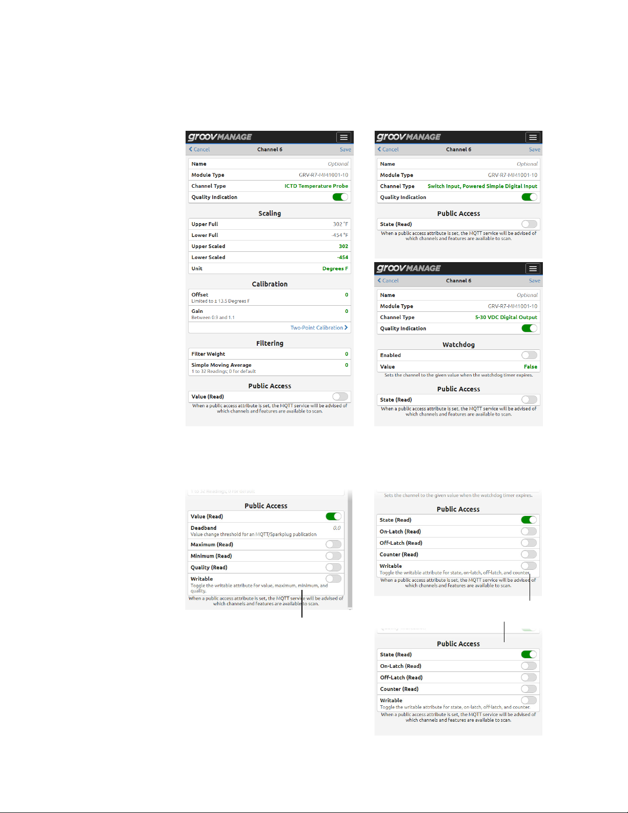
CONFIGURING I/O THROUGH groov MANAGE
Depending on the channel type you select, groov Manage may change the content of channel
page. The following images show a few examples of how the page changes depending on the
channel type you select:
e. If you are transmitting values through MQTT, you want to enable the Value (Read) switch in the
Public Access section. When you do, groov Manage displays another set of switches to help you
identify the specific values you want available to send, as well as whether to make them writable.
Switch Input, Powered Simple Digital Input
ICTD Temperature Probe
5–30 VDC Digital Output
62
groov RIO User’s Guide
Page 71

CHAPTER 8: CONFIGURING I/O
f. Review the rest of the fields on the channel page and make changes based on the needs of your
application. For example, you may want to set a Watchdog timer on a channel or set the scaling
values for a temperature probe.
g. Click Save. groov Manage displays the channel page with information based on your selected
channel type. For the same examples shows in step d, this is what the channel page may look like:
Note that the above image shows channel 6
configured to sense from an ICTD temperature
probe. However, an actual probe has not been
wired to channel 6 on this RIO, which means that
RIO is sensing values that are out of range from
this configuration. RIO reports this as a quality
error.
When you are done configuring all your channels, groov Manage displays your selections on the I/O Channels
page.
If you haven’t already done so, wire your field devices to your RIO as described in “Connecting Field Devices”
on page 11.
CONFIGURING I/O THROUGH CODESYS DEVELOPMENT SYSTEM
After you add the Opto 22 Library Package for CODESYS Development System, you can add groov RIO (and
groov EPIC) devices to your CODESYS projects. In CODESYS, a groov RIO is an Ethernet device, and each
channel is a device you “plug” into that Ethernet device. To select the signal types and features for each
channel, you configure the parameters of the device you “plugged in”. To differentiate between the groov RIO
“device” and the channel “device”, we will include “(groov RIO)” or “(channel)” after each reference to “device”,
as necessary. You may also want to read the note below for more clarification on terminology differences.
Here’s what you need to do to configure I/O through CODESYS Development System:
1. Verify that you have the correct version of the Opto 22 Library Package, CODESYS Development System,
and groov RIO firmware. For guidance on what to check, see “Checking Compatibility Between Library
Package, Development System, and Firmware” on page 64.
2. Add the RIO to your CODESYS project.
3. Add channels by “plugging in” devices.
groov RIO User’s Guide
63
Page 72

CONFIGURING I/O THROUGH CODESYS DEVELOPMENT SYSTEM
4. Select the signal types and configure the features for each channel by editing the “plugged in” device’s
parameters.
Note: Throughout this section, instructions may use CODESYS terminology that differs from standard Opto 22
terminology. For example:
• In the CODESYS Development System interface, the term “device” refers to many different objects: a
controller, an Ethernet adapter, a field device, or an I/O module. In this guide, “device” typically refers
to a field device (a valve, a pump, a quadrature encoder, etc.). When you read sections of the guide
that do not discuss CODESYS, you can interpret references to “device” to mean the latter definition.
• In CODESYS terminology, a groov EPIC processor, a groov RIO, and channels on a groov RIO are
referred to as devices; throughout other sections of this guide, a groov EPIC processor is referred to as
a processor, a groov RIO is referred to as a RIO module, and a channel is referred to as a channel.
• An application, in CODESYS terminology, is roughly equivalent to a PAC control strategy in Opto 22
terminology.
Checking Compatibility Between Library Package, Development System, and Firmware
The CODESYS Development System offers a rich and broad range of support for devices. As with any robust
development system, it’s important to keep up-to-date with releases and review the features, enhancements,
and fixes included in each release, as well as diligently check for compatibility with related software and
firmware. In the CODESYS development environment, it’s important to check compatibility between three
main pieces:
• Opto 22 Library Package for CODESYS Development System. The package contains information for
CODESYS Development System so that it can configure groov EPIC processors, groov I/O modules, and
groov RIO modules. Opto 22 updates the package each time a new module is introduced, as well as to
deliver , and bug fixes. You want to review the readme to learn:
– Which version of the package delivered support for the groov I/O or RIO module you want to use in
your application.
– The features, enhancements, or bug fixes delivered in each version of the package.
– The pre- or co-requisites (for example, a new version of firmware for a groov I/O or RIO module) that
might be required by one of these features, enhancements, or bug fixes.
– Whether the package requires an updated version of the CODESYS Development System.
You should periodically check the Opto 22 website for updates to the package. For instructions on
installing the latest version of the package into CODESYS Development System, see “Updating Device
Information with the Latest Version of Opto 22 Library Package” on page 64.
• CODESYS Development System. The Development System periodically releases features,
enhancements, and bug fixes that may affect how it works with library packages and with device
firmware. It’s important to check that you are running with a version of CODESYS Development System
that is compatible with the Opto 22 Library Package. To check the version number, see the CODESYS
online help.
• groov RIO Firmware. Opto 22 updates the firmware to add enhancements and features or to fix bugs.
Make sure to check the Readme file to learn whether it’s compatible with the version of the Opto 22
Library Package installed in your CODESYS Development System. If you need to update RIO firmware, see
“Updating Firmware on a groov RIO” on page 96.
64
Updating Device Information with the Latest Version of Opto 22 Library Package
If this is the first time you are adding a groov RIO device to your project, you only have to do steps 1, 2, 10, and
11. If you are updating existing RIO devices in your projects, do all of the steps.
groov RIO User’s Guide
Page 73

CHAPTER 8: CONFIGURING I/O
1. Download and install the latest version of the library package from our website.
a. Go to the Opto 22 website, www.opto22.com.
b. Enter “Opto 22 Library Package” in the search box to find the page “Opto 22 Library Package for
CODESYS Development System” and click the link.
c. Click Download and save the package to the same computer where you installed CODESYS
Development System.
d. Open CODESYS Development System and install the package. For instructions on how to do this,
see Installing/Uninstalling a Package in the CODESYS Online Help.
2. Review the readme for the Opto 22 Library Package for CODESYS Development System. Pay particular
attention to the following:
– If the package requires a newer version of CODESYS Development System than your current version,
install the new version before proceeding further.
– Make note of any additional tasks you may have to do after updating device information; for
example, installing a new version of RIO module firmware.
Remember: If you are adding a groov RIO device for the first time, you can skip down to step 10.
3. Open your CODESYS project and, in the Device tree, expand the RIO device to see all the channels.
4. Right-click the RIO device and select Update Device.
5. If the Update Device window does not automatically select the correct RIO device, navigate through the
window to find it and select it.
6. Click Update Device.
CODESYS Development installs the new information about the RIO device. Now you need to update device
information for each channel:
7. Right-click on a configured channel on the RIO device and click Update Device.
groov RIO User’s Guide
65
Page 74

CONFIGURING I/O THROUGH CODESYS DEVELOPMENT SYSTEM
8. In the Update Device window, select the same device type (if it’s not already selected). If applicable,
choose the highest version number. Click Update Device.
9. Repeat step 7 and step 8 for each channel on the RIO.
10. Save your project.
11. If you noted any additional tasks in step 2, make those changes now. Then, rebuild your project, test the
changes, and verify that your application works as expected.
Adding a groov RIO to a CODESYS Project
Before you begin, verify that the PLC and the RIO are on the same network.
1. Open CODESYS Development System.
2. Open your project. (Click File > Open Project. Navigate to the folder where you stored the project file,
select the project file, and then click Open.)
3. Add an Ethernet adapter to your PLC. With this adapter, you will identify which port on the RIO
communicates to the PLC.
a. Right-click on your PLC.
b. Click Add Device.
c. Under Fieldbusses, expand Ethernet Adapter, then click Ethernet.
d. Click Add Device.
e. Click Close.
f. Double-click the Ethernet adapter to open the Ethernet Adapter’s object view.
g. Click the More button ( ) next to the Interface field.
Ethernet Adapter’s object view
The Ethernet Adapter added in steps a through e.
h. Select eth0 or eth1, whichever port is connected to the network.
i. Click OK.
4. Add the RIO to the Ethernet adapter:
a. Right-click on the Ethernet adapter you just added.
b. Click Add Device.
c. Expand Miscellaneous and select a RIO by its part number. For example, GRV-R7-MM1001-10.
d. Click Add Device.
e. Click Close.
5. Assign the RIO’s IP address to the address parameter of the device.
a. Double-click the RIO device you just added. CODESYS Development System opens the object view.
If the Parameters tab is not selected, then select it.
66
groov RIO User’s Guide
Page 75

b. Click on the Value column for the Address parameter. Enter either the hostname or the IP address of
The RIO device added in step 4.
6. Save your project.
Adding Channels and Selecting Signal Types (Plugging in Devices)
To configure a channel, you “plug in” a device to your RIO. Now is when you need the information you
collected when you reviewed “Selecting Functions, Signals, and Features” on page 59.
1. Right-click on a channel (empty slot) and select Plug Device.
CHAPTER 8: CONFIGURING I/O
the RIO, surrounded by single quotes.
Object view of the RIO device added in step 4.
Value column of Address parameter.
Remember to pay careful attention to the channel you select; remember that not all channels support all
functions, signal types, or features.
2. In the Plug Device window, expand Miscellaneous, then select which signal you want to assign to that
channel (device).
3. Click Plug Device.
You can continue adding/configuring channels by clicking on another channel, selecting a signal type in
the Plug Device window, then clicking Plug Device.
4. Click Close when you are done.
Changing Signal Types (Updating Devices)
If you want to change signal type you assigned to a particular channel (device):
1. Right-click on the channel and select Update Device.
2. In the Update Device window, expand Miscellaneous, then select the new signal you want to assign to
that channel (device).
3. Click Update Device.
You can continue changing signal types by clicking on another channel (device), selecting a new signal
type in the Update Device window, then clicking Update Device.
4. Click Close.
Setting Features (Configuring Object Parameters)
In CODESYS Development System, a groov RIO feature is identified as an object’s parameter. For example, an
analog ICTD Temperature signal has several features, which are listed in the table on page 68. In CODESYS
Development System, you would see these features listed as parameters in the Parameters tab of the object
view.
groov RIO User’s Guide
67
Page 76

CONFIGURING I/O THROUGH CODESYS DEVELOPMENT SYSTEM
A
B
A Features for an ICTD signal on a channel of a GRV-R7-MM1001-10. Compare the parameters list with
the list of features on the table for an analog input ICTD signal. All but two features are available on
CODESYS.
B Features for a digital output signal on channel 0 of a GRV-R7-MM1001-10. Compare the parameters
list with the list of features on the table for a digital output DC sinking signal. Only one feature is
available on CODESYS: Watchdog Timeout Value.
The following table lists the features for the functions and signal types that you can select and configure on a
GRV-R7-MM1001-10.
Function Signal Types Features
• Digital
Digital
Input
Channels
Analog
Digital
Output
Channels
For a list of the signal types and features for all RIO models, see Appendix A: Specifications. If a feature listed
in that appendix is not listed in the Parameters tab of the object view, the feature is not configurable through
CODESYS Development System.
Analog
Mechanical
Relay
• Switch Input, powered
• Voltage
• Current
• ICTD
• Thermocouple
• Millivolt
• DC Sinking • On/Off State
• Current
• Voltage
• Form C-NO
• Form C-NC
Channels 0-7:
• On/Off State
Channels 0 & 1:
• Counting
• Scaling
• Offset and Gain
• Average Filter Weight
• Watchdog Timeout Value
• Scaling
• Clamping
• Watchdog Timeout Value
• On/Off State
• Watchdog Timeout Value
68
Configuring Channel Features (Device Parameters)
1. If you haven’t started CODESYS Development System, start it and open your project.
2. Open or select the Devices view, then expand the Ethernet branch of your groov RIO.
groov RIO User’s Guide
Page 77

CHAPTER 8: CONFIGURING I/O
3. Double-click the device (channel) you want to configure. CODESYS Development System opens the
object view for that device. Check that the Parameters tab is selected.
4. Find the parameter (feature) you want to configure:
– For devices (channels) with scaling: If you want to set scaling values, first determine the upper
and lower ends of the scale. For example, if your input range is ± 150 mV and it is connected to a
tank that can hold 1000 liters, you can set the lower end of the scale (-150 mV) to represent 0 liters
and the upper end of the scale (+150 mV) to represent 1000 liters. With a signal type of Analog In
±150 mv (for example, on a GRV-R7-MM1001-10):
– On the Upper Scaled row, double-click the Value cell and enter 1000.
– On the Lower Scaled row, double-click the Values cell and enter 0.
To set default scaling, leave the Value cells blank or enter 0.
– For devices (channels) with clamping: If you want to limit the output sent out from the device
(channel), first determine the upper and lower end of that range. For example, suppose you want
the output range to be 5–15 mA. On a signal type of Analog Out 0-20 mA (for example, on a
GRV-R7-MM1001-10), to limit the range to 5–15 mA:
– On the Upper Clamp row, double-click the Value cell and enter 15.
– On the Lower Clamp row, double-click the Value cell and enter 5.
To set no clamping, set both Values cells to 0.
– For devices (channels) with counting: If you want to use the counting feature, you must select it.
On the Feature row, double-click the Value cell to display the drop-down arrow.
Click the arrow to display a list, then select Counter.
5. Repeat step 4 for each device (channel) you want to configure.
Remember to save your project periodically.
If you haven’t already done so, wire your field devices to your RIO as described in “Connecting Field Devices”
on page 11.
groov RIO User’s Guide
69
Page 78

UNDERSTANDING HOW QUALITY ERRORS ARE REPORTED
UNDERSTANDING HOW QUALITY ERRORS ARE REPORTED
Some signal types on a groov RIO can report quality errors, which are common errors like input values that are
out of range. groov Manage can show you that there is a quality error in the I/O Channels page by highlighting
the channel yellow and showing brief message about the quality error.
Viewing Information About a Quality Error
1. Log into your groov RIO with a user ID that has administrator privileges.
2. Click I/O Channels. groov Manage displays the list of channels and highlights the channel that is
reporting the quality error with a yellow background.
Click on that channel.
3. groov Manage displays the specific information about that channel:
The Quality field shows you a message with an error code number and a possible reason for the error.
This information can help you troubleshoot problems with a field device wired to that specific channel.
70
groov RIO User’s Guide
Page 79

9: Enabling MQTT
WHAT IS MQTT?
MQTT is a publish/subscribe (pub/sub) protocol that’s suited to many IIoT applications because of its
architecture.
In a pub/sub architecture, a central source, called a broker, receives, distributes, and in some cases, retains
data. MQTT clients can publish data to the broker or subscribe to get data from a broker (or both). Clients who
publish data send it only when they choose to publish. Clients who subscribe to data automatically receive it
from the broker only when the publishers sends data.
Contrast this with a client/server architecture. With this architecture, the client and server must be connected,
because the client requests data directly from the server. The client doesn’t know when the data changes, so it
must request it at regular intervals.
MQTT pub/sub offers three main advantages over client/server for IoT applications:
• Network traffic is reduced overall because data is published and sent only when it changes, rather than at
regular intervals.
• Because the broker is a central source that manages data, the broker can take over the data management
workload typically handled by a server in a client/server model, and the server now handles fewer clients.
And even remote devices with irregular connections or low bandwidth can publish or subscribe to data.
If a publisher can’t connect to the broker, for example, the publisher can optionally buffer its data and
send it at a later time.
• For data publishers and subscribers, there’s another important advantage: data is published and
subscriptions are initiated through an outbound connection. Most firewalls block inbound connection
requests (for example, an external OPC client requesting data from an internal OPC server), but they allow
outbound connections over secure TCP ports. A device (in this case, RIO) initiates an outbound
connection through a secure port, and the traffic travels both directions through that connection.
See mqtt.org for more information about the protocol.
MQTT on groov RIO
One of the features of MQTT is that the data (payload) it transmits can be in a format best suited for the
application. groov RIO can transmit payloads formatted to meet the Sparkplug-B specification or formatted as
strings. In addition, RIO offers several features and capabilities to suit a variety of application requirements.
Review the following list of features and capabilities and select the option that best suits your application:
• MQTT with string payloads—Select this option if:
– Your application requires that the payload be formatted as a string.
– Your application is simple, perhaps monitoring or controlling only a few devices.
groov RIO User’s Guide 71
71
Page 80

CONFIGURING AND ENABLING MQTT WITH STRING PAYLOADS
– Your application requires automation data from groov RIO, but not from other PLCs.
– You are looking for a cost-effective option. This option does not require the purchase of additional
licenses.
With this option, you will need to:
– Convert data within your application. With payloads formatted as strings, you will need to add logic
to your application to convert strings to the correct data type, when necessary.
– Define the topic namespace.
• MQTT with Sparkplug payloads published from
– Your application requires that the payload be formatted to comply with the Sparkplug specification.
– Your application requires automation data from groov RIO, but not from other PLCs.
– You are looking for a cost-effective option. This option does not require the purchase of additional
licenses.
With this option, you’ll be able to queue data into RAM if network connectivity is lost, which will then be
transmitted when the service is available. However, because the queued data is stored in RAM, it can be
lost when power is cycled or space runs out.
Keep in mind that you will need to:
– Define the topic namespace.
– Provide the MQTT configuration information through groov Manage and then enable the service.
Note that you cannot combine these two options; you must choose one or the other.
• For MQTT with string payloads, see “Configuring and Enabling MQTT with String Payloads” on page 72.
• For MQTT with Sparkplug payloads published from groov RIO, see “Configuring and Enabling MQTT with
Sparkplug Payloads from groov RIO” on page 75.
groov RIO—Select this option if:
CONFIGURING AND ENABLING MQTT WITH STRING PAYLOADS
To connect your groov RIO to an MQTT infrastructure, you will need to:
• Create a new MQTT broker or establish access to an existing one. The broker can be located on your
premises or in the cloud. You can search the Internet for information from various vendors about MQTT
brokers; setting up an MQTT broker is not covered in this guide.
• Configure and start the MQTT service through groov Manage.
Before configuring, it’s helpful to first collect information about the MQTT broker, determine some identifying
information for RIO, and review settings that may affect transmission performance.
Collecting Information
Collecting information about the MQTT broker
You’ll need the following information about the MQTT broker:
• Broker URL—The URL of the MQTT server
• Client ID— (Optional) Enter a client ID only if one was supplied. If you do not enter a client ID, the MQTT
service will generate one.
• Username—The username you need to access the broker
• Password—(Optional) If required, the password you need to access the broker
• SSL—If your MQTT server requires SSL, you need to upload the correct SSL certificate to your groov RIO
before you begin configuring the MQTT service. For instructions, see “Managing the SSL Security Features
of your groov RIO” on page 24.
• Keep Alive (s)—The number of seconds between heartbeats.
72
groov RIO User’s Guide
Page 81

CHAPTER 9: ENABLING MQTT
Specifying Default Topics for groov RIO
You’ll need to collect or create the following information to uniquely identify your groov RIO in your MQTT
infrastructure. If necessary, consult with someone who assigns topics to determine if RIO will be assigned a
specific set of topics, and whether you should follow a particular naming convention. All of the following
information is required:
• MQTT Base Topic—The base topic is prefixed to the MQTT topic used to publish data.
• MQTT Group Topic—Identifies the group that your groov RIO belongs to
• MQTT Subgroup Topic —Identifies a subdivision within the group
In addition, you’ll need:
• MQTT Device Topic—Identifies your groov RIO within the subgroup
• Use Comma in Floats—If your application uses a comma to separate values (for example, pi is denoted
as 3,14 instead of 3.14), you’ll want to indicate that when you enter configuration information in
groov Manage.
Reviewing groov RIO Performance Settings
You may want to review the following settings, which can affect throughput in an MQTT infrastructure.
Changing the settings can help you fine-tune throughput:
• CommTimeout (ms)—The default connection timeout value is 5000 milliseconds. You can adjust this
value to account for slower or faster infrastructures. (For example, if your groov RIO is in an area with
“spotty” or slow connection, you may want to increase this value.) Minimum is 1000; maximum is 30,000.
• Scan Time (ms)—The scan interval in milliseconds. You may need to adjust this if the scans can’t finish
before the time is up.
Configuring and Enabling MQTT Service
Make sure you are logged into your groov RIO with an ID with administrator privileges before starting:
1. From the groov Manage Home page, click MQTT, then Configuration.
2. In the Edge Node section:
groov RIO User’s Guide
73
Page 82

CONFIGURING AND ENABLING MQTT WITH STRING PAYLOADS
a. Click MQTT Payload.
b. Click MQTT with string payloads.
Enter the information you collected in “Specifying Default Topics for groov RIO” on page 73.
3. Click Add MQTT Broker.
Enter the information you collected in “Collecting information about the MQTT broker” on page 72. Click
OK to close the MQTT Broker window and return to the MQTT page.
74
groov RIO User’s Guide
Page 83

CHAPTER 9: ENABLING MQTT
4. Click Add Device.
Enter the information you collected in “Reviewing groov RIO Performance Settings” on page 73.
Note: Ignore the Additional Host Tasks field; RIO does not have host tasks.
5. Click Save. groov Manage validates the information you entered.
If it passes this validation, click Yes to confirm that you want to save these settings and start the MQTT
service. This may take a minute. When it is done, groov Manage displays the MQTT page.
CONFIGURING AND ENABLING MQTT WITH SPARKPLUG PAYLOADS FROM groov RIO
To connect your groov RIO to an MQTT infrastructure, you will need to:
• Create a new MQTT broker or establish access to an existing one. The broker can be located on your
premises or in the cloud. You can search the Internet for information from various vendors about MQTT
brokers; setting up an MQTT broker is not covered in this guide.
• Configure and enable the MQTT service through groov Manage.
Before configuring, it’s helpful to first collect information about the MQTT broker, determine some identifying
information for RIO, and review settings that may affect transmission performance.
Collecting Information
Collecting information about the MQTT broker
Collect the following information about the MQTT broker:
• Broker URL—The URL of the MQTT server
• Client ID— (Optional) Enter a client ID only if one was supplied.
• Username—The username you need to access the broker
• Password—(Optional) If required, the password you need to access the broker.
groov RIO User’s Guide
75
Page 84

CONFIGURING AND ENABLING MQTT WITH SPARKPLUG PAYLOADS FROM groov RIO
• SSL—If your MQTT server requires SSL, you need to upload the correct SSL certificate to your groov RIO
before you begin configuring the MQTT service. For instructions, see “Managing the SSL Security Features
of your groov RIO” on page 24.
• ConnTimeout (ms)—The default connection timeout value is 5000 milliseconds. You can adjust this
value to account for slower or faster infrastructures. (For example, if your groov RIO is in an area with
“spotty” connection, you may want to increase this value.) Minimum is 1000; maximum is 30,000.
• Keep Alive (s)—The number of seconds between heartbeats. If there is no heartbeat for longer than the
keep alive time, the last will and testament is sent.
• Compression—If you must compress the payloads before they are published to the MQTT server,
determine if it uses gzip or deflate.
Specifying Unique Identifiers for groov RIO and Other Settings
You’ll need to collect or create the following information to uniquely identify your groov RIO in your MQTT
infrastructure. If necessary, consult with someone who assigns these IDs to determine if the processor will be
assigned a specific set of IDs, and whether you should follow a particular naming convention.
• Group ID—Identifies the group that your groov RIO belongs to
• Edge Node ID—Identifies a subdivision within the group
• Device ID—Identifies your groov RIO within Edge node
You may also need the Primary Host ID, which enables notifications as to the “state” (offline or online) of the
MQTT server.
Reviewing Performance Settings
You may want to review the following settings, which can affect throughput in an MQTT infrastructure.
Changing the settings can help you fine-tune throughput:
• CommTimeout (ms)—The number of milliseconds that the MQTT service waits for RIO to respond to a
request. If you set this value too small, you may see erratic communication timeouts.
• Scan Time (ms)—The scan interval in milliseconds. You may need to adjust this if the scans can’t finish
before the time is up.
• Historic Queue—The maximum number of Sparkplug publications that may be historically queued
when the connection to the broker fails. The value may range from 0 to 65535. You may want to change
this value after considering the following factors:
– The publications are stored in RAM, so storage can be consumed quickly when you specify a large
value. Also keep in mind these three factors that can influence how many Sparkplug publications
are created: how many tags are scanned, the scan rate, and the rate of tag changes.
– If the number of publications exceeds this value, the oldest entries are discarded to make room for
newer entries.
Configuring and Enabling MQTT Service
Make sure you are logged into your groov RIO with an ID with administrator privileges before starting:
76
groov RIO User’s Guide
Page 85

CHAPTER 9: ENABLING MQTT
1. From the groov Manage Home page, click MQTT, then Configuration.
If MQTT with Sparkplug payloads is not listed in the MQTT Payload field, click on the field and select it
from the MQTT Payload window.
2. In the Edge Node section, enter the information you collected in “Specifying Unique Identifiers for groov
RIO and Other Settings” on page 76.
3. Click Add MQTT Broker. In the MQTT Broker page, enter the information you collected in “Collecting
information about the MQTT broker” on page 75.
Click OK.
groov RIO User’s Guide
77
Page 86

CONFIGURING AND ENABLING MQTT WITH SPARKPLUG PAYLOADS FROM groov RIO
4. Click Add Device.
Enter the information you collected in “Reviewing Performance Settings” on page 76.
Note: Ignore the Additional Host Tasks field; RIO does not have host tasks.
5. Click Save. Confirm that you want to save these settings and start the MQTT with Sparkplug service. This
may take a minute. When it is done, groov Manage displays the MQTT page.
6. Enable the service by clicking Enable in the MQTT Status section.
78
groov RIO User’s Guide
Page 87

10: Developing Node-RED Flows
If you are new to Node-RED, it might be helpful to review our Automation 101 video introducing Node-RED:
Intro to Node-RED: Part 1 - Fundamentals. (You can find other videos in the Support > Videos section of our
website, www.opto22.com.) The “Learning to Develop a Node-RED Flow” section (below) will take you
through a hands-on approach to learning how to develop a Node-RED flow. However, before you can begin
those exercises or do anything else with Node-RED on your groov RIO, make sure you:
• Enabled Node-RED as described in “Enabling Node-RED” on page 56.
• Configured the channels on your RIO by one of the following methods:
– As described in Chapter 8: Configuring I/O.
– Configured through a PAC Control strategy.
– Configured through a custom control program.
FOR EXPERIENCED Node-RED DEVELOPERS
If you have experience developing Node-RED flow and just want to know which node to install to access I/O
on your groov RIO, it is node-red-contrib-groov-io. This node can also access I/O on groov I/O modules
mounted on an EPIC chassis.
You might also find the following nodes helpful:
• node-red-contrib-groov. Nodes to access a Data Store in a groov View project.
• node-red-contrib-pac. Nodes to access tags and strategy information from a PAC Control strategy
running on a groov EPIC processor or SNAP PAC controller.
These are the URLs to access the Node-RED Editor in groov RIO:
• https://[your groov RIO’s hostname]/node-red
• https://[your groov RIO’s IP address]/node-red
LEARNING ABOUT Node-RED ON RIO
Opto 22 provides Node-RED nodes to access groov RIO I/O; the same nodes can also access I/O on a
groov EPIC processor. Opto 22 also provides Node-RED nodes to access data in groov View Data Stores, as well
as nodes to access strategy information from PAC Control strategies running on groov EPIC processors or
SNAP PAC controllers. For more information on nodes, see developer.opto22.com.
Node-RED Editor. You can include one or many flows in your Node-RED project, which you build in the
standard, browser-based Node-RED Editor. You can access the editor directly through a URL or navigate to it
through groov Manage.
groov RIO User’s Guide 79
79
Page 88

LEARNING TO DEVELOP A Node-RED FLOW
Debugging. With few programming restraints, it’s easy to accidentally introduce bugs into your flow. The
Node-RED Editor can help you debug flows. If Node-RED crashes, it automatically restarts. You can also start
and stop Node-RED yourself from within groov Manage.
Files. Your Node-RED project consists of two files: the main file with all your flows, and a separate file
containing all the sensitive credential information used by some nodes, such as usernames and passwords for
an email node. groov RIO provides ways to backup and restore Node-RED projects, either separately or as part
of the complete backup and restore.
LEARNING TO DEVELOP A Node-RED FLOW
If you are new to Node-RED, this section takes you step-by-step through the following exercises:
• Learning the different ways to open the Node-RED Editor in groov RIO.
• Creating a basic flow to display a timestamp; deploying the flow, operating a node, and observing its
behavior; then enhancing the flow to modify the format of the timestamp.
• Adding nodes that can collect data from your RIO, a groov View Data Store, and a PAC Control strategy.
• Creating and deploying a flow that accesses tag values from a fictional PAC Control strategy.
Before you start these exercises, make sure you enable Node-RED (see “Enabling Node-RED” on page 56) and
that your groov RIO has access to the Internet.
Opening the Node-RED Editor
You can open the Node-RED editor with either of the following methods:
• Open a web browser and enter either of the following in the URL bar:
– https://[your groov RIO’s hostname]/node-red
– https://[your groov RIO’s IP address]/node-red
Don’t forget the “s” in https. Examples:
– https://opto-00-d2-da/node-red
– https://192.0.2.20/node-red
• If you are in groov Manage, click the menu button ( ), then select Home. From the Home page, click
on Node-RED, then Open Node-RED Editor.
80
groov RIO User’s Guide
Page 89

CHAPTER 10: DEVELOPING NODE-RED FLOWS
If you are new to the Node-RED Editor, take a moment to review the following diagram to familiarize yourself
with the different parts of the editor.
Nodes palette Workspace Menu
Tips
box
Creating a Flow
1. In the Nodes palette on the left, locate the inject node. Click and hold on it, then drag it to the workspace.
The inject node lets you inject messages into a flow, either by clicking the button on the node or by
setting a time interval between injects.
The info tab on the right side-bar displays information about the inject node’s properties and a
description of what it does:
You might want to close the Tips box so that you can see more information in the info tab.
2. Scroll down in the Nodes palette and locate the debug node. Drag it to the workspace.
groov RIO User’s Guide
81
Page 90

LEARNING TO DEVELOP A Node-RED FLOW
3. Wire the inject and debug nodes together by dragging from the output port of inject to the input port of
debug.
Deploying the Flow and Testing It
The nodes exist only in the editor and must be deployed to the server.
1. Click the Deploy button in the upper right.
2. In the right-sidebar, select the debug tab. (If you can’t see the debug tab, click .)
3. Click the button on the left side of the inject node.
Numbers appear in the sidebar:
This number is a timestamp representing the number of milliseconds since January 1, 1970. This is the
default payload of the Inject node.
Adding a Function Node
Let’s make the timestamp more readable by using a Function node. Function nodes let you pass each
message though a JavaScript function. If you don’t know JavaScript, you may be able to find code you need
using an Internet search.
1. Find the function node in the Nodes palette.
2. Click and hold on the function node, then drag it to the workspace, placing it between the inject and
debug nodes. When the wire between the inject node and debug node becomes a dashed line, let go of
the mouse button. The Node-RED editor automatically wires the Function node to the inject node and
the debug (msg.payload) node.
82
groov RIO User’s Guide
Page 91

CHAPTER 10: DEVELOPING NODE-RED FLOWS
If you didn’t see a dashed line:
a. Drop the function node near the inject and debug node.
b. Delete the existing wire by selecting it and pressing Delete on the keyboard.
c. Add a wire to link the output of the inject node to the input of the function node.
d. Add a wire to link the output of the function node to the input of the debug (msg.payload) node.
3. Double-click the Function node to edit it. The Node-RED editor displays the Edit function node panel.
4. In the Name field, type Human Date.
5. Copy the following code into the Function field, at line 1:
// Create a Date object from the payload
var date = new Date(msg.payload);
// Change the payload to be a formatted Date string
msg.payload = date.toString();
6. Leave this code in place at the end:
return msg;
7. Click Done to close the edit dialog box and then click the Deploy button.
8. Now when you click the Inject button, the message in the sidebar shows a more readable time stamp:
Installing groov I/O Nodes
groov I/O nodes can read and write data from your RIO or from I/O modules on an EPIC.
1. Click the menu button ( ), then select Manage palette.
2. Click the Install tab.
3. In the search field, enter groov.
groov RIO User’s Guide
83
Page 92

LEARNING TO DEVELOP A Node-RED FLOW
4. Find node-red-contrib-groov-io in the list and click the Install button next to it.
5. The Node-RED Editor displays a message about checking dependencies and reviewing node
documentation. Click Install. When installation is finished, the small Install button changes color to gray
and changes text to Installed.
Install tab
Search field
groov View nodes
groov I/O nodes
While you are here, you can also install the groov View nodes. This will help you save some steps in the next
section, “Installing groov View Nodes to Access Data Stores” on page 85. The following image shows both nodes
installed.
6. Click Close.
The new groov I/O and groov View nodes appear in the nodes palette, under the heading Opto22.
84
groov RIO User’s Guide
Page 93

CHAPTER 10: DEVELOPING NODE-RED FLOWS
Installing groov View Nodes to Access Data Stores
groov View nodes can read and write data from a groov View Data Store. For an introduction to Data Stores and
how to create them in groov View, see “Adding a Data Store” in the groov View User’s Guide (form 2027). After
you create the Data Store in groov View, you can access the Data Store in your Node-RED flow by accessing the
groov View project that contains the Data Store.
If you already installed the node-red-contrib-groov nodes to the Node palette when you went through “Installing
groov I/O Nodes” on page 83, you can skip to the next section.
1. Click the menu button ( ), then select Manage palette.
2. Click the Install tab.
3. In the search field, enter groov.
Install tab
4. Find node-red-contrib-groov in the list and click the Install button next to it.
Search field
groov View nodes
groov I/O nodes
The Node-RED Editor displays a message about checking dependencies and reviewing node
documentation. Click Install. When installation is finished, the small Install button changes color to gray
and changes text to Installed.
The following image shows both groov I/O and groov View nodes installed.
groov RIO User’s Guide
85
Page 94

LEARNING TO DEVELOP A Node-RED FLOW
5. Click Close.
The new groov I/O and groov View nodes appear in the nodes palette, under the heading Opto22.
Installing Opto 22 PAC Control Nodes
For this section, you’ll add nodes to establish real-world communication with groov View Data Stores and tags
in PAC Control strategies. You need either of the following:
• An Opto 22 groov EPIC processor running a PAC Control strategy, or
• a SNAP PAC S-series or R-series industrial controller with firmware R9.5 or higher, running a PAC Control
R9.5 or higher strategy.
For either of these options, you need to complete the configuration instructions on developer.opto22.com. At
the website, click on Node-RED for PAC Control, then expand Getting Started.
• For the groov EPIC processor, click on groov EPIC Controller Configuration.
• For the SNAP PAC controller, click SNAP PAC Controller Configuration.
As you complete the processor or controller configuration, make sure to save the following information:
• API Key Name and Value (for SNAP PAC)
• API Key (for groov EPIC)
• Path and file name to the SSL Certificate
After you set everything up and gathered this information, you can start:
1. Install Node-RED for PAC Control nodes just as you installed the groov View nodes. (Menu > Manage
palette > Install tab. Search for node-red-contrib-pac.)
2. Make sure you have an inject and a debug node in the workspace.
86
groov RIO User’s Guide
Page 95

CHAPTER 10: DEVELOPING NODE-RED FLOWS
3. Near the bottom of the Nodes palette, click and hold on the pac read node and drag it to the workspace,
in between inject and debug (msg.payload).
The pac read node lets you read I/O and variable data in the PAC Control strategy.
4. Wire the pac node to the inject node and debug node, in the same way you wired the Function node.
5. Click the node and click the info tab to see helpful information about the node.
6. Double-click the pac read node to edit it.
7. Click the pencil at the right of the Controller field.
8. Complete the fields:
a. For Address, choose a protocol and enter the IP address of the groov EPIC processor or the SNAP PAC
controller.
b. For the API Key Name and API Key Value fields:
– If you are accessing tags from a PAC Control strategy running on a SNAP PAC Controller, enter
the API Key Name and Value you obtained when you configured the controller (as described
on the previous page).
– If you are accessing tags from a PAC Control strategy running on a groov EPIC processor, enter
the API Key into the API Key Value field. Leave the API Key Name field blank.
c. For the SSL Certificates (PEM format) fields:
– If you selected HTTPS as the protocol, read the information in the info tab to determine what
to enter in these fields.
– If you selected any other protocol, you can leave these fields blank.
d. Click Add.
The Node-RED editor returns you to the Edit pac read node panel, where your node is now configured to
access the I/O and variable data in the PAC Control strategy running on the groov EPIC processor or the
SNAP PAC controller:
groov RIO User’s Guide
87
Page 96

LEARNING TO DEVELOP A Node-RED FLOW
9. Choose the Data Type from the dropdown list.
The data type determines what other fields appear. In this example we chose Analog Input, so a field
appears for Tag Name.
a. Tag Name—Enter the exact I/O point or variable name from the PAC Control strategy running on
this controller. If you leave this field blank, you’ll receive values for all tags of this type (in this
example, all analog inputs).
b. Start Index and Length—For a table, enter the starting index and length of the data you want to
use.
c. Node Name—(Optional) By default, the tag name is used for this node. If you want to give it a
different name, enter it here.
d. Click Done.
10. Click the down arrow next to Deploy to see your choices.
88
groov RIO User’s Guide
Page 97

CHAPTER 10: DEVELOPING NODE-RED FLOWS
You can deploy everything, or if you don’t want to disturb running
flows, you can choose to deploy only the changed flows or
changed nodes.
The gray box around the icon shows what will happen when you
click the Deploy button. In this example, everything is deployed
(Full).
11. Click Deploy. Now click the inject button and see what message appears in the debug tab.
You should see the data from your PAC Control strategy. Here’s how our example looks:
groov RIO User’s Guide
89
Page 98

LEARNING TO DEVELOP A Node-RED FLOW
90
groov RIO User’s Guide
Page 99

11: Maintaining a groov RIO
You’ll want to maintain your groov RIO units regularly to keep them up-to-date, running smoothly, and to
make it easier to restore in the event of a reset:
• Back up your information regularly
• Apply firmware updates
If you encounter problems while operating your groov RIO unit, here are a few things you can do:
• You can troubleshoot some problems and, if you can’t resolve your problems, there are some steps you
can take to help Product Support solve your problems.
• If you had to restore your processor to factory defaults, you can restore the information that you backed
up.
BACKING UP YOUR groov RIO SETTINGS
Recommendations vary regarding when and how often you should back up your groov RIO:
• Before you apply a firmware update.
• Before you change configuration, like channel function.
• Periodically; for example, once a year.
Whichever recommendation you follow, the groov Manage Backup feature can save valuable configuration
information, which you can then restore at a future date.
However, keep in mind the following:
• The backup feature saves only the first 10 MB of user files, which are files that either you uploaded
manually to the processor or were placed there by control programs.
• While the backup feature does save your Node-RED projects (flows and credentials), it does not save any
nodes you installed; for example, Opto 22 nodes or nodes to access cloud services.
IMPORTANT: The backup file is not a secured or encrypted file. You must apply your own security or encryption
to the file to protect any sensitive information. Also, be aware that if you send a backup file to Opto 22 without any
security or encryption, our personnel will have access to all the information in that file.
After you select a back up folder or medium, do the following steps:
1. On a computer or mobile device that is connected to the medium or folder where you want to save your
back up file, log into your groov RIO with a user ID that has administrator privileges.
2. Click Maintenance > Backup.
groov RIO User’s Guide 91
91
Page 100

BACKING UP YOUR GROOV RIO SETTINGS
3. On the Backup page, select the information you want to back up by moving the corresponding slider to
the right so that it shows green ( ). By default, everything except Server SSL Certificates and
network configurations are backed up. If you do not want certain information backed up, move the slider
to the left so that it shows grey ( ).
– I/O Configuration—Saves the changes you made to the channels at the time you ran the backup.
– Accounts—The user IDs and passwords, plus the scope of each user ID’s access.
– Networking—Saves all of the following:
– Hostname
– The settings for the Ethernet 0 (ETH0) and WiFi.
– The settings for the OpenVPN Tunnel 0.
– The settings for the Network Options (DNS server IP address(es) and domain name(s), gateway
IP address, the DNS order, and the gateway order).
This also includes sensitive information like the WiFi SSID and pre-shared key, and the OpenVPN
server login credentials. If you select this setting, it’s important that you apply your own security or
encryption to the backup file to protect this information.
– Firewall—The firewall settings you selected, as well as any rules you created.
– Time—The time zone and time servers configurations.
– Node-RED—Part of a Node-RED project can include a credentials file, which can contain sensitive
information like user names, passwords, and security keys. It’s important that you apply your own
security or encryption to the backup file to protect this information.
Remember that any nodes you installed (like Opto 22 nodes or nodes to access cloud services) are
not included in the backup.
– MQTT/Sparkplug—The information you entered or selected when you configured your groov RIO
unit to work with Sparkplug.
– Client SSL Certificates—The most recent SSL certificates you may have uploaded.
– User Files—Only the first 10 MB of files you uploaded manually or were placed there by control
programs. After you create the backup file, you can review the log file to see which user files were
stored in the backup file and which were not.
– USB Settings—The enable and automount settings you chose.
– Server SSL Certificates—The server SSL certificates include sensitive information, like the web
server’s private key. If you select this setting, it’s important that you apply your own security or
encryption to the backup file to protect this information.
4. Click Download Backup.
5. Navigate to the folder or media where you want to store the backup file. groov Manage includes the date
and time (in UTC) that you ran the backup as part of the file name. If you want to give it a different name,
change the name in the File name field. Click Save.
92
NOTE: Some browsers might automatically download the file to a specific folder. Check your browser’s
downloads settings to determine where the browser stored the backup file.
6. Opto 22 recommends that you apply some form of security on the backup file.
7. (Optional) To check which user files the backup may have missed, in groov Manage, click the menu
button ( ), then select Info and Help. Click Logs > groov Manage.
groov RIO User’s Guide
 Loading...