

Page 1
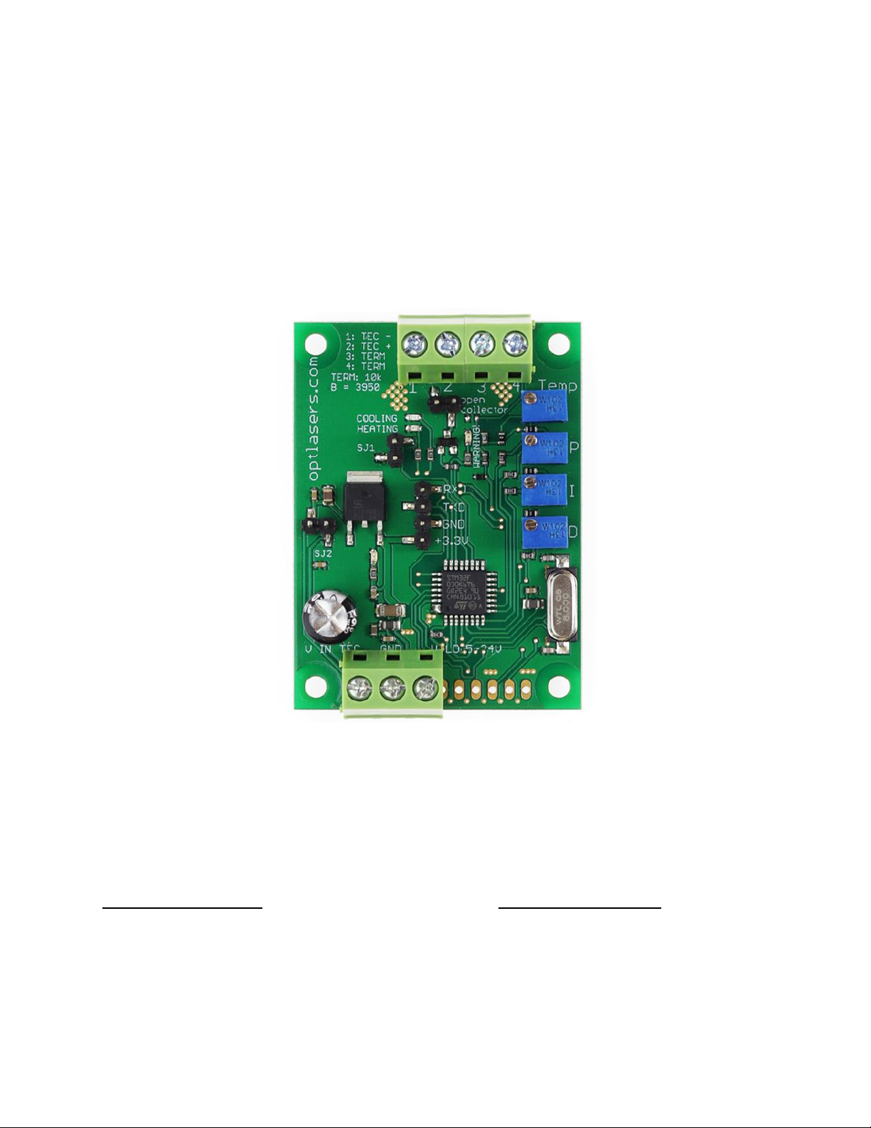
TEC-8A-24V-PID-HC
Operating Manual
Contact and Shipping:
Company Information:
Tomorrow's System Sp. Z o.o.
Tomorrow's System Sp. Z o.o.
Okulickiego 7/9 hala G39
Pułaskiego 125/35
05-500 Piaseczno
15-337 Białystok
Poland
Poland
tel.: +48 515 180 752
NIP: PL5423238556
Page 2

Table of content
Product Description 3
Technical Data 4
Pinout 5
Electrical Wiring 6
Advanced Program 9
Opened/Not connected SJ1 jumper mode 9
Closed/Connected SJ1 jumper mode 10
Connectivity 11
Serial Protocol 12
Configuration command 12
Single byte commands 12
How to connect PC to TEC 8A-24V-PID 13
Communication via PuTTY: 15
Basic Program 18
Recommendations and Requirements 21
Protection 21
Related products 22
Page 3

Product Description
TEC-8A-24V-PID-HC is improved digital temperature controller. The present
version can heat and cool without changing any jumpers. The controller is available
in two versions of the program: Basic and Advanced. Beyond the basic functionality,
Advanced version offers the possibility to set various parameters of the controller
using UART.
TEC-8A-24V-PID-HC has an open collector output which allows to use it as a
signal for other devices. Open collector will indicate when the measured
temperature is out of the Tmin/Tmax range. In addition to open collector, warning
LED will indicate this also. The indication LEDs show heating or cooling activity.
Also, the dimensions of the PCB are smaller and mounting holes were added.
You can use UART to read the temperature setpoint, actual temperature and
PID parameters values. To read accurately the value of the temperature use a
thermistor with BETA value of 3950 for basic and advanced versions and for
advanced ±100°C version you need a P0K1.202.3FW.B.007 thermistor.
Its small size, simplicity of regulation and versatility make it widely used in
many areas. It is dedicated to work with 12 V thermocouples (Peltier modules) yet
it does well with all modules whose supply voltage falls in the range of 5 to 24 V.
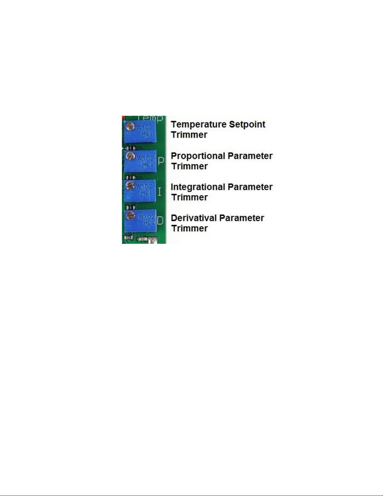
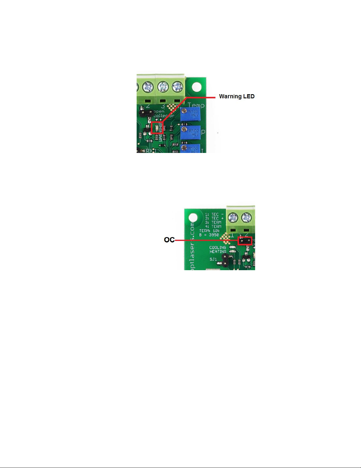
With the use of four trimmers, the temperature setpoint as well as values of
the PID controller parameters can be set. The controller operates in PWM mode
(Pulse Width Modulation) and can control currents of up to 8 A. For the temperature
sensor, it uses a standard 10k NTC B=3950 thermistor for basic and advanced
version and for advanced ±100°C version it uses a P0K1.202.3FW.B.007
thermistor. By default, the temperature setpoint is set to 25 degrees Celsius.
Due to the possibility to set the parameters of a PID controller, the driver can
be adapted to almost any system. Depending on the inertia of the system, properly
adjusted driver is able to maintain the desired temperature with an accuracy better
than ±0.05°C.
The current flowing through the Peltier cell depends on the supply voltage
used. Most of the common modules should be supplied with the voltage of 5 to 24V,
and the maximum current that flows through them is defined by a cell symbol.
The driver is working in TTL 3.3V standard.
Page 4

Technical Data
RS232 Programmable
Temperature
Controller ±100°C
(Advanced)
RS232 Programmable
Temperature
Controller
(Advanced)
Temperature
Controller (Basic)
Maximum current
8A
Input Voltage (V LOG)
5 – 24 V
Input Voltage (V TEC)
5 – 24 V
Serial Interface
3.3V Logic, 1 start bit = 0, 8 data bits, no parity, 1 stop bit = 1
Serial Transmission
Yes
Serial Reception
Yes
No
Temperature
Stabilization Accuracy
±2°C*
±2°C
±2°C
Temperature Tracing
Accuracy
±0.05°C
Cooling or heating
work
Yes
Temperature sensor
P0K1.202.3FW.B.007
10k NTC B=3950
Temperature range
Tmin and Tmax
-100 to +100°C
0 to +50°C
0 to +50°C
Heat sink required
No
Dimensions
45 x 60 mm
Mounting holes
37 x 52 mm
Mounting holes
diameter
3.2 mm
* Applicable for the range ±50°C. For the range ±100°C accuracy is ±3°C
Page 5

Pinout
Electrical Wiring
Page 6
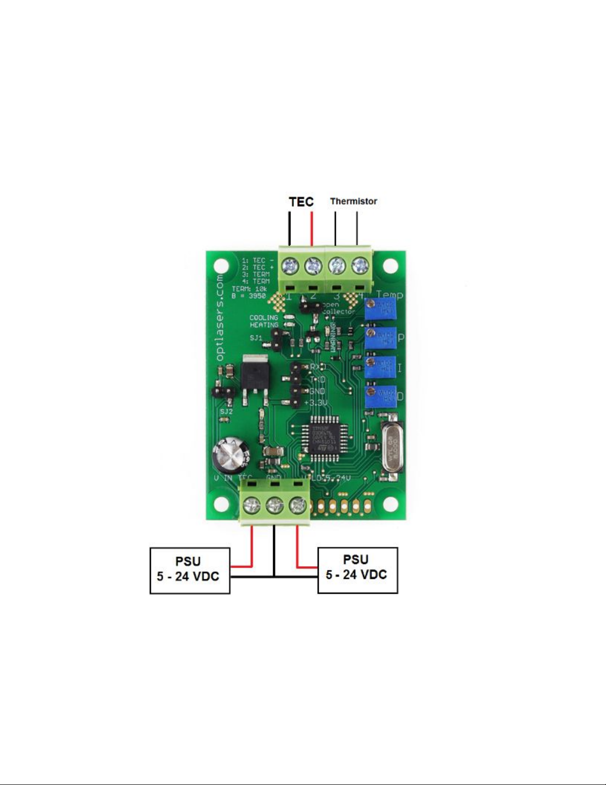
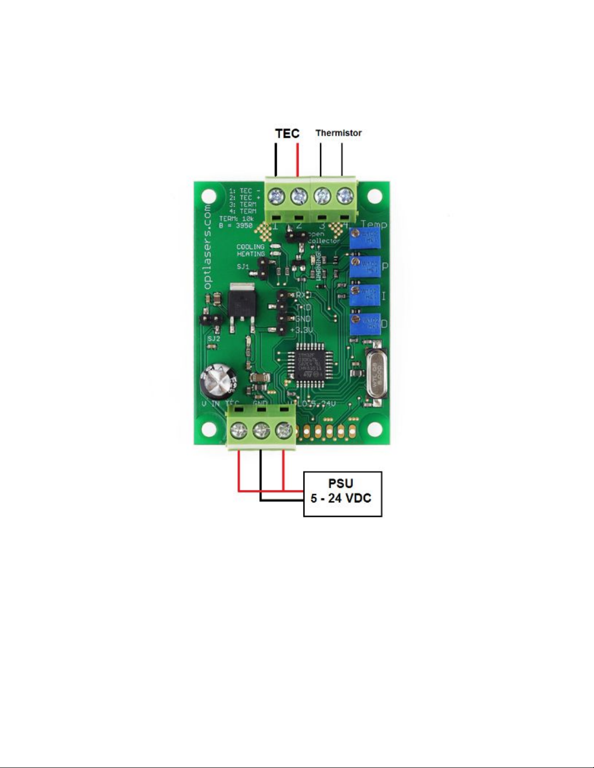
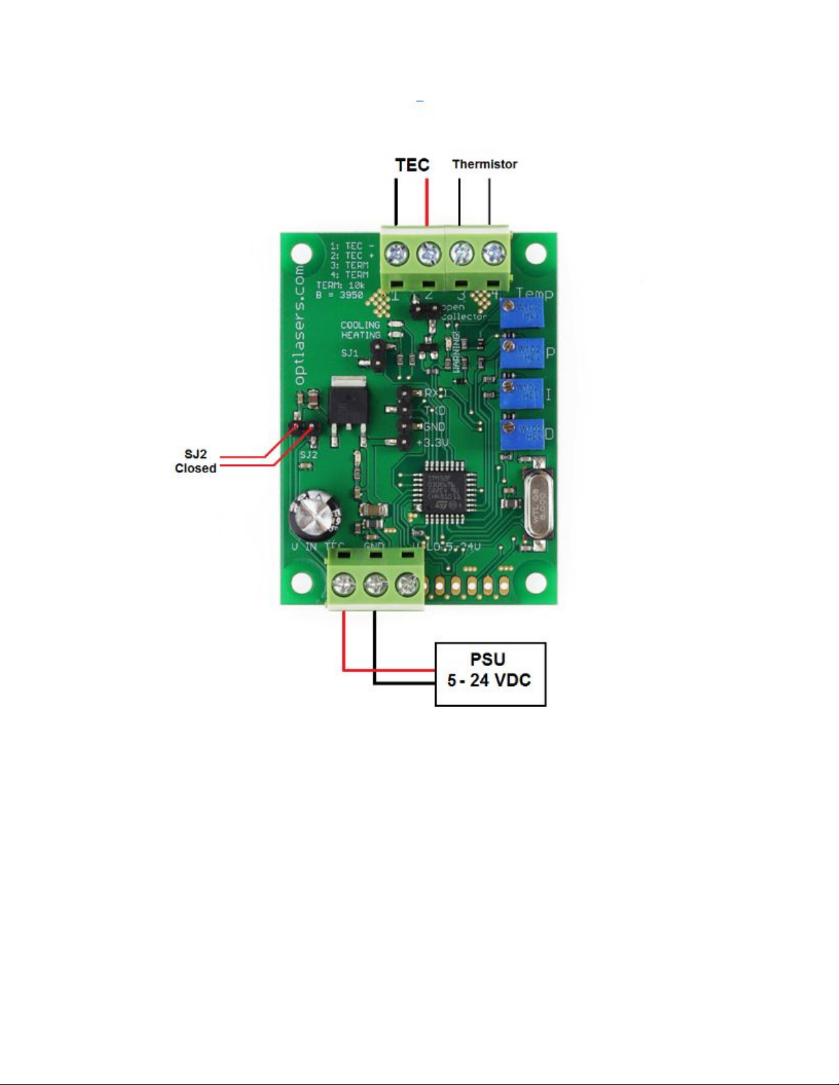
The TEC-8A-24V-PID-HC driver can be power supplied in three different ways.
1. Using two PSUs:
2. Using one PSU:
Page 7
3. Using one PSU with closed SJ2:
Page 8
Page 9
Advanced Program
Opened/Not connected SJ1 jumper mode
1. Adjustment with the use of four trimmers. Trimmers allow to set PID
parameters, as well as the temperature setpoint.
2. The system detects a lack of connection with the thermistor and then
switches WARNING LED on. As long as the connection is lost, the driver will
not take any action and the open collector output is grounded.
3. If the measured temperature exceeds an overriding limit of +70°C in the NTC
10k versions (+120°C in the Advanced -100/+100 version), the Peltier
module is switched off.
4. If the measured temperature is out of Tmin...Tmax range, the WARNING LED
is ON and the open collector output (OC) is connected to ground. The PID
regulator works normally (unless the overriding limit mentioned before is
exceeded). In the Advanced versions, when the SJ1 jumper is open, Tmin
and Tmax have fixed values: 0°C and 70°C respectively in the Advanced NTC
10k version, and -120°C and +120°C respectively in the Advanced
-100/+100 version. In the Advanced versions, Tmin and Tmax can be set by
the user (through the serial connection) and the settings become valid when
the SJ1 jumper is closed.
Page 10
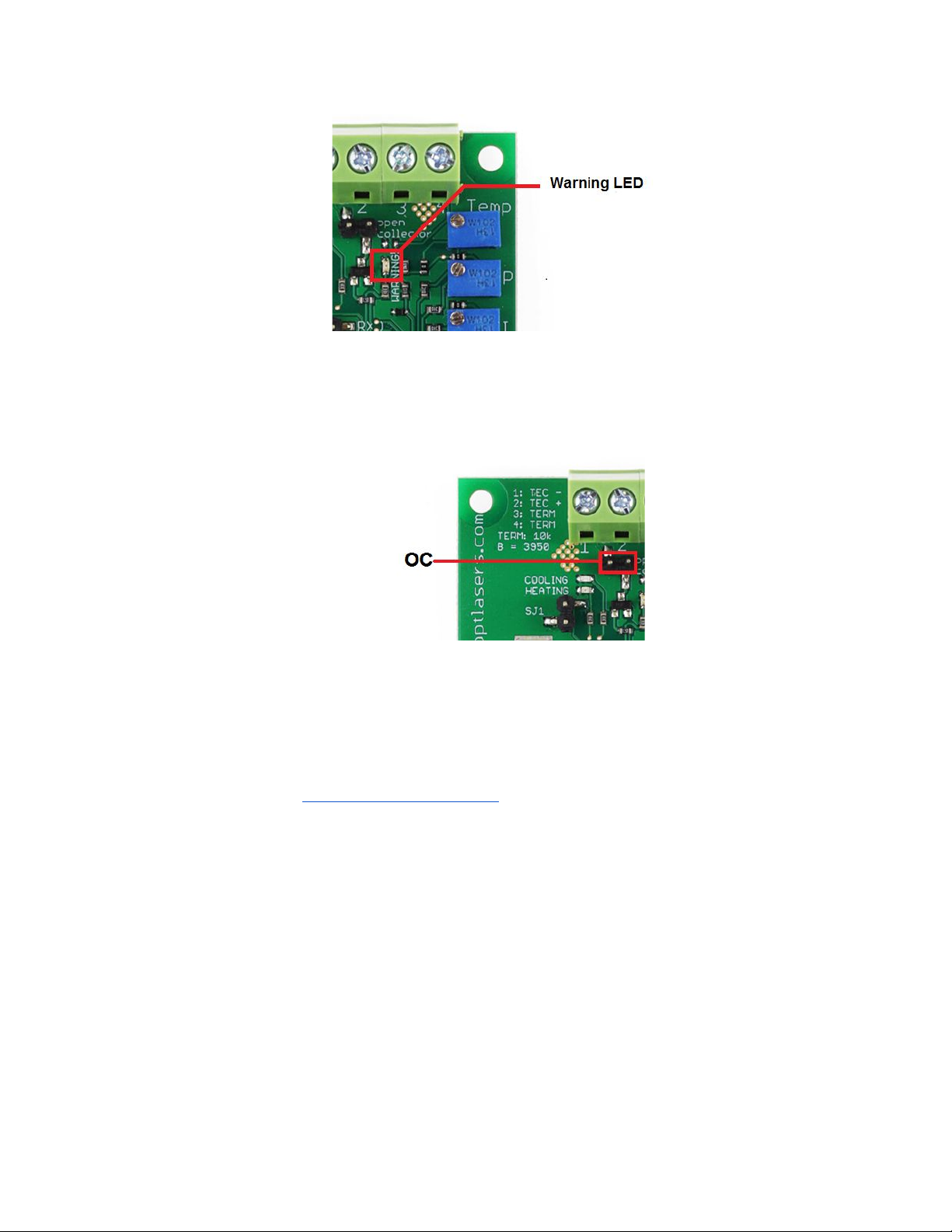
5. If the measured temperature lies between +45°C and Tmax, the WARNING
LED is flashing. The open collector output (OC) is not connected to ground.
The PID regulator works normally (unless the overriding limit mentioned
before is exceeded).
Closed/Connected SJ1 jumper mode
1. Adjustment with use of UART port
Using PC and USB to TTL converter it is possible to send (valid only for
advanced version) and read parameters to/from the regulator. While using this
mode, trimmers are not working, and user gets control via USB to TTL
communications which allows of automatization of cooling and heating process.
Additionally, it is possible to set Tmax and Tmin values which are checked by the
driver (OC and Warning LED).
Page 11
Connectivity
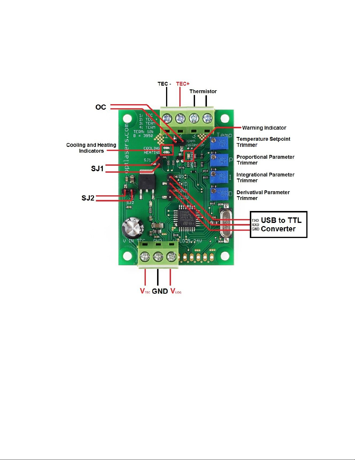
Figure 1. TEC 8A-24V-PID Connection scheme
UART parameters:
● 38400 bits / second
● 8 data bits
● even parity: No parity
● stop bits: 1
● flow control: No
Page 12

Communication with the device requires terminal software installed on the
PC. User can use his favourite terminal software. This guide contains example how
to set up a connection with the device using PuTTY software with Windows 7
operating system.
Serial Protocol
Protocol allows user to set configuration parameters of the device or acquire
measured data using commands specified below. Each command is a set of ASCII
characters which may be followed by <CR> and/or <LF>.
Configuration command
Command template: <T
setpoint
P I D T
min
T
max
>
T
setpoint
[°C] – target temperature value. The device checks output temperature via
thermistor and manages output current to reach temperature setpoint.
P – PID proportional coefficient (in range from 0.0 to 20.0)
I – PID integral coefficient (in range from 0.0 to 20.0)
D – PID derivative coefficient (in range from 0.0 to 20.0)
T
min
[°C] - lower threshold which is checked by the driver (OC)
T
max
[°C] - upper threshold which is checked by the driver (OC)
Example: <10 4.5 1 30.6 0 60.7>
Single byte commands
These are single character commands without additional parameters:
o – print single readout
R – turn ON cyclic print (print every second).
r – turn OFF cyclic print
A - switch ON TEC supply
a - switch OFF TEC supply
Page 13

Template of readout: <T
setpoint
P I D T
min
T
max
T
measured
OC PWM>
T
setpoint
[°C] – target temperature value set by user
P – set PID proportional coefficient (in range from 0.0 to 20.0)
I – set PID integral coefficient (in range from 0.0 to 20.0)
D – set PID derivative coefficient (in range from 0.0 to 20.0)
T
min
[°C] - lower threshold which is checked by the driver (OC)
T
max
[°C] - upper threshold which is checked by the driver (OC)
T
measured
[°C] - instantaneous value of measured temperature
OC - status of the open collector (0 – disconnected from GND or 1 – connected to
GND)
PWM [%] - Negative values indicate cooling phase and positive ones indicate
heating phase. The absolute value of the parameter inform about intensity.
How to connect PC to TEC 8A-24V-PID
After setting up connections (Figure 1) and powering up the TEC 8A-24V-PID
we should check if the converter has been recognized and installed in system
(Figure 2). In our case USB to UART converter driver has been installed without
problems.
If you experience any problems with driver installation you should check the
official website of the manufacturer of the converter device you use.
Page 14
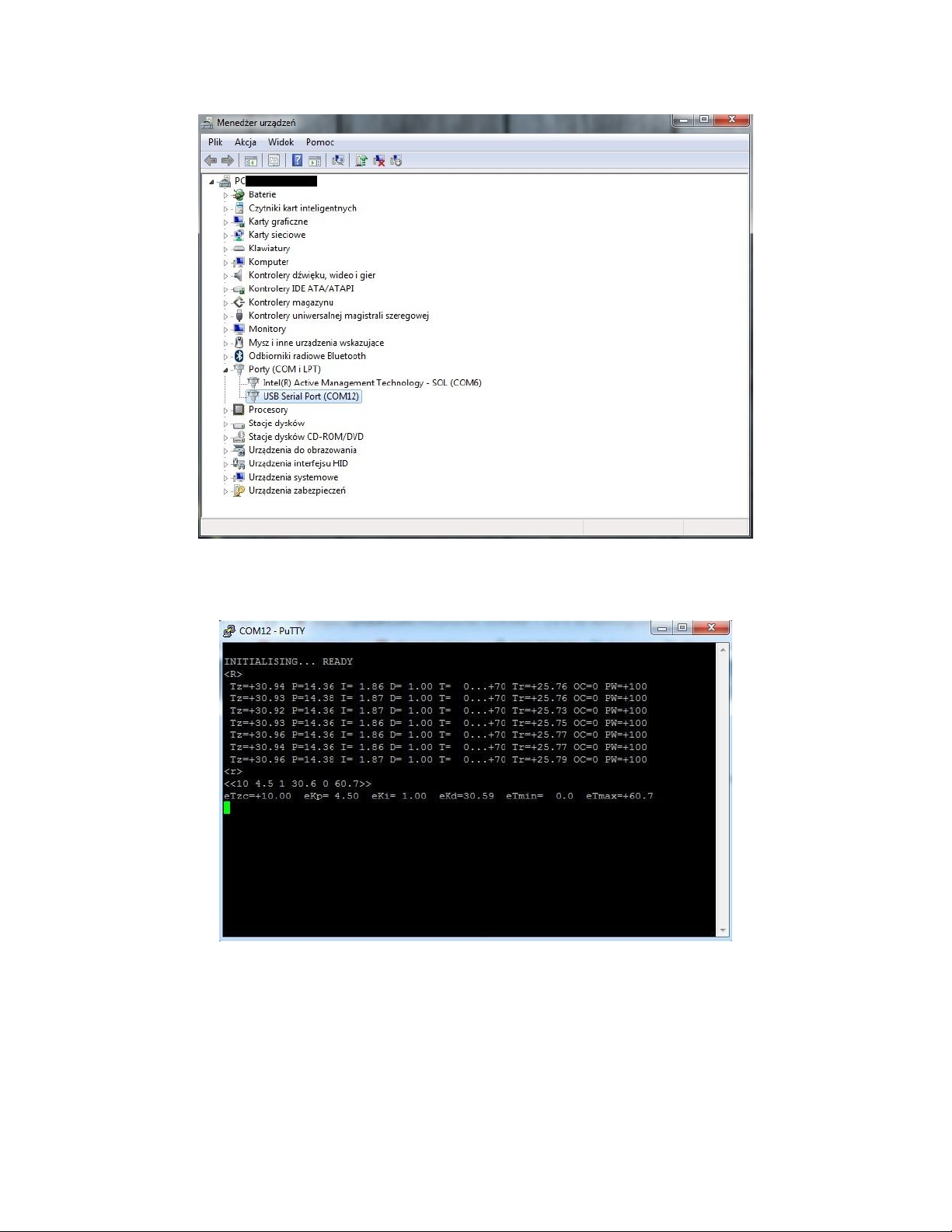
Figure 2. Device Manager – USB to UART converter driver is installed (COM12)
Page 15
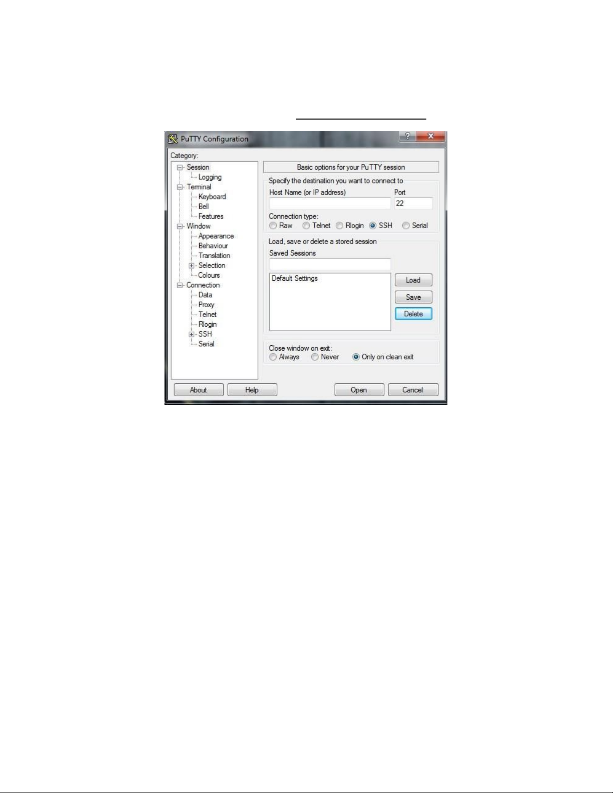
Communication via PuTTY:
1. Download and open PuTTY. (Visit https://www.putty.org/ for details)
2. Open category Connection->Serial. Make sure transmission parameters are
set properly (look for chapter TEC 8A-24V-PID Connectivityand check
parameter values). In field Serial line to connect to write the name (COM)
of the USB to UART converter shown in the device manager operating system
(Figure 2.)
Page 16

3. Open category Session and switch connection type to Serial. Value in the
field Serial line and Speed should update. There is an option to save
configuration. You can name configuration in field under Saved sessions
then press the Save button. The list will update. To use one of saved
configurations simply check one from the list then press Load button.
Page 17
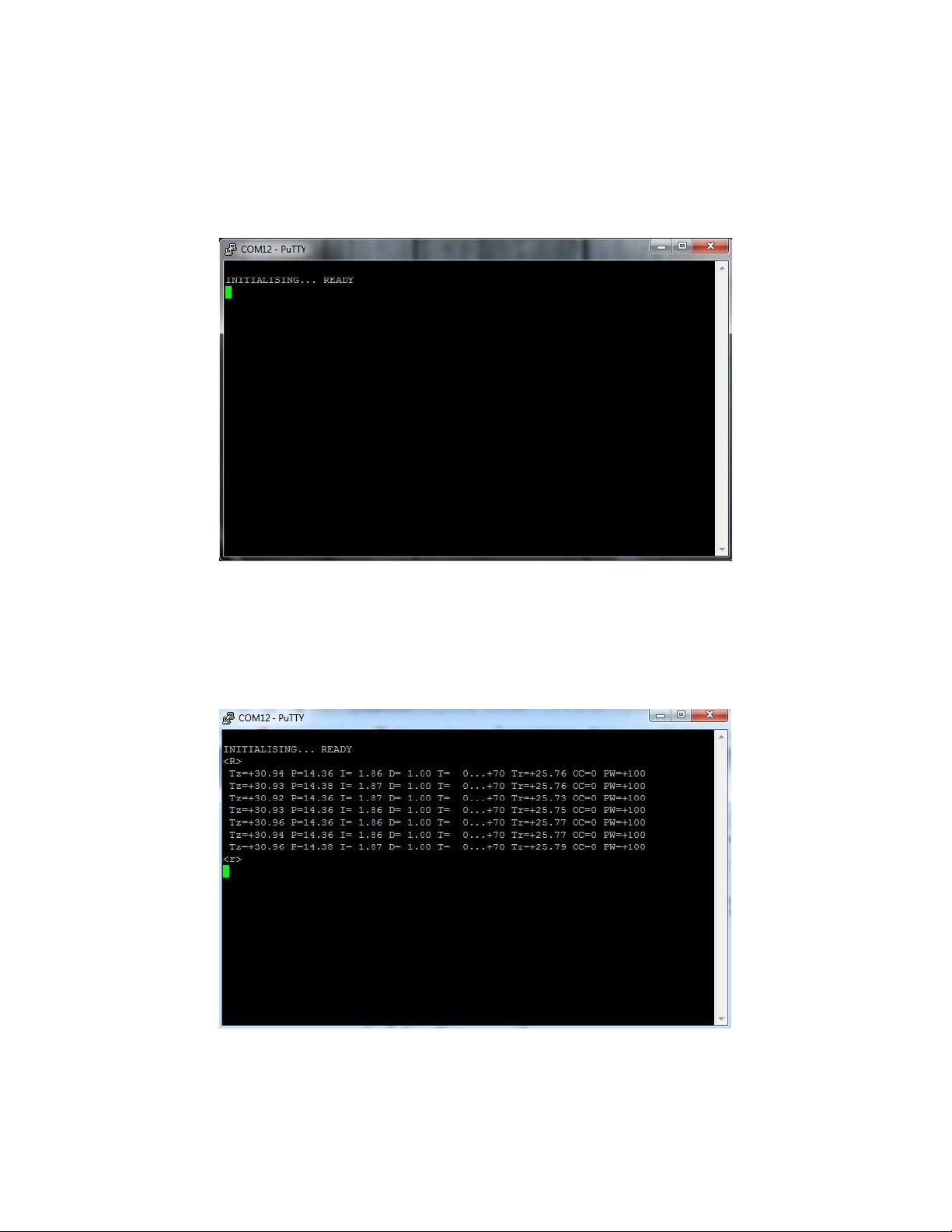
4. After setting up the session parameters click the Open button. The terminal
window will show up. If you want to make sure TEC 8A-24V-PID is connected
properly you can reset the device. Simply disconnect it from the power
supply and after couple seconds connect again. You will receive initialization
info from the device (shown below).
5. Now we are able to send commands to the device. Single byte commands
can be send by hand. Type R and after couple of seconds type r.
6. To send a configuration command you should write it first in any text editor,
copy it and press the right mouse button on the terminal window. This is an
Page 18
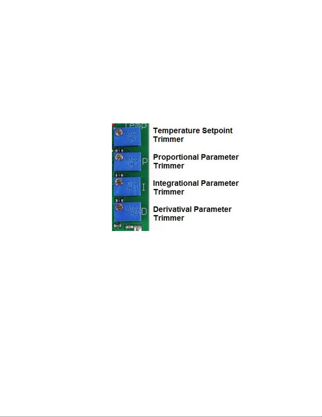
inconvenience that is improved in other software (RealTerm, Hyper Terminal
etc.).
Basic Program
1. Adjustment with the use of four trimmers. Trimmers allow to set PID
parameters, as well as the temperature setpoint.
2. The system detects a lack of connection with the thermistor and then
switches WARNING LED on. As long as the connection is lost, the driver will
not take any action and the open collector output is grounded.
3. If the measured temperature exceeds an overriding limit of +70°C in the NTC
10k versions (+120°C in the Advanced -100/+100 version), the Peltier
module is switched off.
4. If the measured temperature is out of Tmin...Tmax range, the WARNING LED
is ON and the open collector output (OC) is connected to ground. The PID
regulator works normally (unless the overriding limit mentioned before is
exceeded). In the Basic version, Tmin and Tmax are 0°C and 70°C
Page 19
respectively. In the Basic versions, Tmin and Tmax cannot be set by the user
(through the serial connection).
5. If the measured temperature lies between +45°C and Tmax, the WARNING
LED is flashing. The open collector output (OC) is not connected to ground.
The PID regulator works normally (unless the overriding limit mentioned
before is exceeded).
6. In the Basic version SJ1 is not working;
7. Open collector (OC) is grounded, Warning LED is ON and Peltier current is
OFF at more than 70 degrees Celsius;
8. When temperature drops below 70 degrees, the driver goes back to normal
work;
9. The parameters exchanged with UART:
Tz - Temperature setpoint
Tr - Temperature measured
P - proportional parameter 0.0 - 20.0
I - integral parameter 0.0 - 20.0
D - derivative parameter 0.0 - 20.0
Example:
Page 20

Recommendations and Requirements
We recommend the use of power cables with a minimum cross-section of
0.5mm2.
TEC-8A-24V-PID-HC uses serial port (COM) to communicate with PC. There
are a lot of desktop applications which can be used to read out data, sending from
the controller and to write in parameters (Advanced version). Below, there are only
a few examples:
● RealTerm (Windows)
● Minicom (Linux)
● PuTTY
If you are able to program, you can also write your own application. There
are a lot of libraries for serial communication in any programming language.
Protection
The system detects a lack of connection with the thermistor and then
switches WARNING LED on. As long as the connection is lost, the driver will not
take any action and the open collector output is grounded.
If the measured temperature exceeds an overriding limit of +70°C in the NTC
10k versions (+120°C in the Advanced -100/+100 version), the Peltier module is
switched off.
If the measured temperature is out of Tmin...Tmax range, the WARNING LED
is ON and the open collector output (OC) is connected to ground. The PID regulator
works normally (unless the overriding limit mentioned before is exceeded). In the
Basic version, Tmin and Tmax are 0°C and 70°C respectively. In the Advanced
versions, Tmin and Tmax have fixed values when the SJ1 jumper is open: 0°C and
70°C respectively in the Advanced NTC 10k version, and -120°C and +120°C
respectively in the Advanced -100/+100 version. In the Advanced versions, Tmin
and Tmax can be set by the user (through the serial connection) and the settings
become valid when the SJ1 jumper is closed.
If the measured temperature lies between +45°C and Tmax, the WARNING
LED is flashing. The open collector output (OC) is not connected to ground. The PID
Page 21

regulator works normally (unless the overriding limit mentioned before is
exceeded).
Attention: This temperature controller has no reverse polarity protection.
Reverse polarity at power supply will permanently damage the temperature
controller.
Related products
● TEC-8A-24V-PID-HC-RS232 Programmable Temperature Controller -100
+100*C
● TEC-8A-24V-PID-HC-RS232 Programmable Temperature Controller
● TEC-8A-24V-PID-HC Temperature Controller
 Loading...