

Optivisus DKM01B, DKM1BT, VDKM01BR User Manual
DVI KVM & USB, RS232 , IR ,Analog Audio CAT5 Extender over IP
ITEM NO: DKM01B (DKM1BT+VDKM01BR) DVI KVM & USB, RS232 , IR, Audio CAT5
Extender over IP
The DKM01B DVI KVM, USB with Analog audio, RS232, and IR CAT5 extender design for extends and
distribute all signals over one CAT5e up to 150 meters, with local HDMI monitor output. It provides
superior video quality up to 1920 x 1200 resolutions, and using cost effective Cat5e cable, instead of DVI,
RS232 cables, for an easy, neater and reliable installation. The local and remote units can be connected
together for a Point-to-Point connection via CAT5e/6 cable or a Point-to-Many connection via a managed
network switch. It is optimized for applications at broadcasting system, multimedia display and multi-data
sharing, digital signage, home network integration, and industrial control, hospital, education, security, Matrix
network system and system control over RS232 and equipment control over IR.
Features:
Extend and distribute DVI signal with bi-directional RS232, USB signal,IR and analog audio signals
over LAN.
Supports resolutions up to 1080p Full HD and 1920 x 1200 (WUXGA) 32bpp@ 60 Hz
Transmission range up to 150M over CAT5e, 180M over CAT6.
Support window based management software, using PC computer for easy setting input/output
link.
Support Android/iOS APP control.
Receiver input source select could be from IR remote control or front panel button.
Built in RS232 distribution function, to send RS232 signal from one TX to multiple RX.
Supports 2-way RS232 commands at baud rate 115200 (control software on a PC, or other
automated control system hardware) to control devices attached to the matrix using RS232. Full
Duplex data communication.
Built in Bi-Directional analog audio transmission (only in point to point mode ).
Built in Bi-Directional IR.
DKM01BT transmitter unit built in DVI local loop output.
VDKM01BR receiver unit with 4 ports USB devices (1 port USB 1.1 & 3 Port USB 2.0), to extend
USB peripheral devices, such as flash disk, hard disk, keyboard, mouse, etc.
Use IGMP and Jumbo frame protocol Gigabit Switch Hub to do HD signal distribution and transmission.
Support point to point and multiple source devices to multi-display connections via Gigabit network
switch.
The system could be works with any combination on HDMI, DVI, VGA transmitters and receivers.
Support total of transmitter unit up to 16 pieces, receiver unit over 254 pieces based on the number of
ports on your network switch.
Perfect for large scale remote HD content access and security monitoring systems, digital signage
applications.
Optional model:
SR01: Signal repeater for longer distance application.
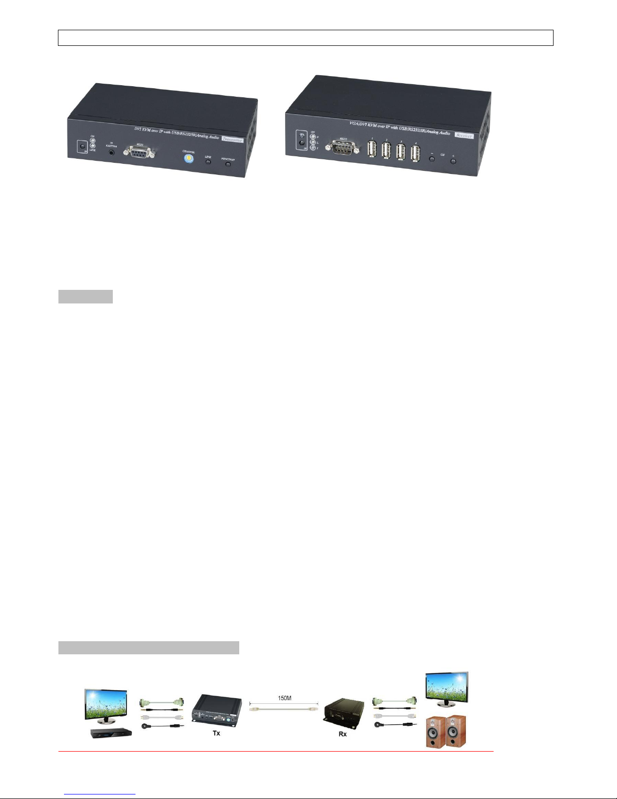
Application and Installation View:
Point to Point Direct Connection: (Extender)
2
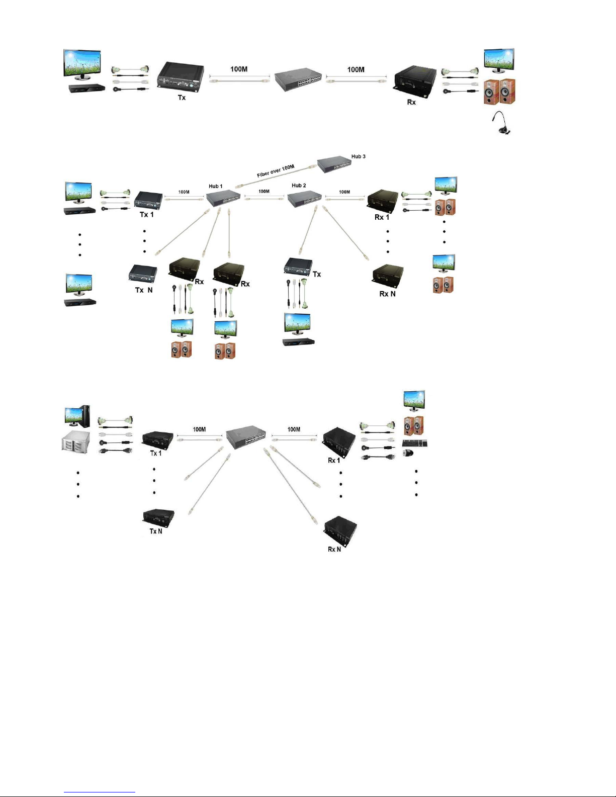
Point to Point With Switch Hub Connection: (Extender over LAN)
Multiple TX to Multiple RX via Switch Hub Connection
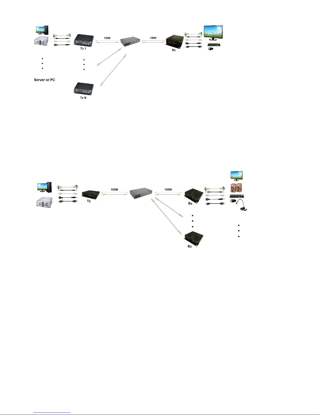
Multiple TX to Multiple RX Connection: (Matrix Switcher)
Multiple TX to One RX r Connection: (KVM Switcher over IP)
3
One TX to Multiple RX Connection: (Splitter)
Optional Model: (order separately)
SR01 Signal Repeater
Extend data signal for an additional 120meters.
Application for DKM01B signals for extra long range transmission.
Ability to cascade connection with multiple SR01 for long range transmission
Built in LED status indication.
External power required.
Plug and play for easy installation.

4
5
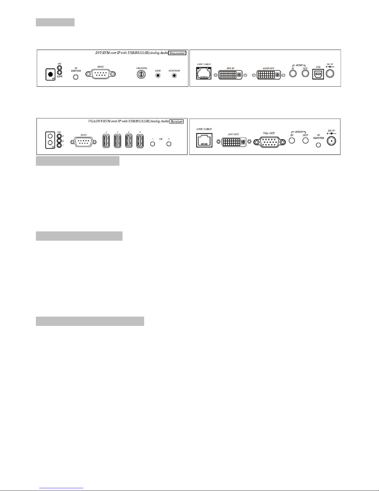
Panel View:
Transmitters
DKM01BT
Receivers
VDKM01BR
Video Output Setting:
VDKM01BR support both DVI and VGA output, default is DVI output only.
To change the output setting please press below button 5 seconds till power LED flash, it will
reboot automatically ( about 30 seconds to reboot).
[CH-]: VGA output only
[CH+]: DVI output only
[CH-] and [CH+]: DVI and VGA output both
Notice: in both mode the DVI monitor must be connected and power on.
LED Indication Status:
Power (Green LED): Flash Booting
ON Boot completed
Link (Blue LED): Flash Connecting or connected but no HDMI input
ON Transmitter connected with Receiver
Receiver IR (Red LED): On Received IR signal
Flash IR signal status / Enter IR learning mode
RJ45 LED Indication Status:
Green Flash Data transmission
Orange On Ethernet connected
6
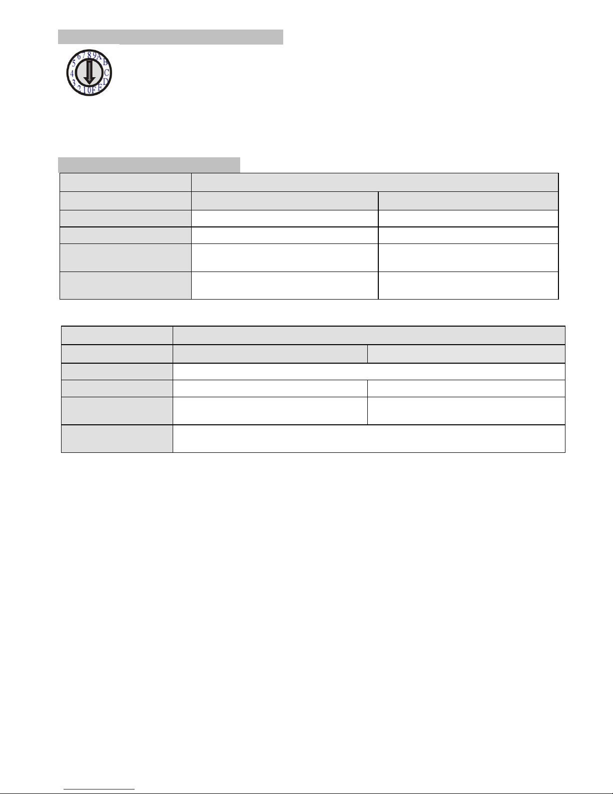
Back Panel Rotary Switch Function:
Transmitter and receiver must setting at same channel in order to do mutual transmission.
Rotary switch to be follow 16 HEX, could switch “ 0 ~ F “ total 16 channels, A = channel 10, B = channel 11,
others channel same as 16 hex conversion.
Transmitter channel setting must be unique to avoid conflict with any other transmitters.
Front Panel Button Function:
ITEM
TRANSMITTER
Button
LINK
FUNCTION
Short Press
Remote output (on / off)
Video Mode / Graphic Mode
Long Press (3 seconds)
Loop output (on / off)
Anti-Dither (1/2/off)
Press to power on (Hold until
Green LED Flash)
N/A
Update EDID from loop output
Press to power on (Hold until
Green and Blue LED Flash)
RESET to Default
N/A
Above “bold font” part as the default
ITEM
RECEIVER
Button
CH. -
CH. +
Press together
Confirm / Enter menu
Short Press
Reduce the numbers of Channel/Menu/Value
Increase the numbers of Channel/Menu/Value
Press 5 seconds
(VDKM01BR only)
VGA output only
DVI output only
Press 5 seconds together
(VDKM01BR only)
DVI and VGA output both
(DVI monitor must be connected and power on)
Above “bold font” part as the default

7
RJ45 pin define:
Link Cable (TIA/EIA-568-B)
1. Orange-white Data 1 +
2. Orange Data 1 -
3. Green-white Data 2 +
4. Blue Data 3 +
5. Blue-white Data 3 -
6. Green Data 2 -
7. Brown-white Data 4 +
8. Brown Data 4 -
Cable & Transmission Distance:
Link Cable use high quality Cat.5e UTP/STP/FTP or Cat.6 UTP cable
Transmission distance will be affected by equipment (Switch HUB), cable quality…etc. When
using CAT.5e the max. Transmission distance up to 150M, using CAT.6 cable up to 180M.
You can also use model no: SR01 repeater for extended longer distance or using Gigabit Switch
hub which support IGMP protocol and Jumbo Frame 8K for signal distribution or extend distance.
System Default Settings:
Transmitter / receiver support Unicast and Multicast two mode, default is Multicast.
In Multicast mode it could be one to one, one to multi, multi to on or multi to multi applications.
The analog audio output of transmitter and input of receiver will be off in this mode, analog audio
only from transmitters send to receivers.
Analog audio bi-direction transmission only in Unicast mode, please refer to the web setting
chapter: Casting Mode
System default IP setting is Auto IP, it will assign 169.254.X.X (submask 255.255.0.0) to
transmitters and receivers, you could also set to DHCP or Static IP, please refer to web setting
chapter: IP Setup.
 Loading...