

DVI KVM & USB, RS232 , IR ,Analog Audio CAT5 Extender over IP
ITEM NO: DKM01B (DKM1BT+VDKM01BR) DVI KVM & USB, RS232 , IR, Audio CAT5
Extender over IP
The DKM01B DVI KVM, USB with Analog audio, RS232, and IR CAT5 extender design for extends and
distribute all signals over one CAT5e up to 150 meters, with local HDMI monitor output. It provides
superior video quality up to 1920 x 1200 resolutions, and using cost effective Cat5e cable, instead of DVI,
RS232 cables, for an easy, neater and reliable installation. The local and remote units can be connected
together for a Point-to-Point connection via CAT5e/6 cable or a Point-to-Many connection via a managed
network switch. It is optimized for applications at broadcasting system, multimedia display and multi-data
sharing, digital signage, home network integration, and industrial control, hospital, education, security, Matrix
network system and system control over RS232 and equipment control over IR.
Features:
Extend and distribute DVI signal with bi-directional RS232, USB signal,IR and analog audio signals
over LAN.
Supports resolutions up to 1080p Full HD and 1920 x 1200 (WUXGA) 32bpp@ 60 Hz
Transmission range up to 150M over CAT5e, 180M over CAT6.
Support window based management software, using PC computer for easy setting input/output
link.
Support Android/iOS APP control.
Receiver input source select could be from IR remote control or front panel button.
Built in RS232 distribution function, to send RS232 signal from one TX to multiple RX.
Supports 2-way RS232 commands at baud rate 115200 (control software on a PC, or other
automated control system hardware) to control devices attached to the matrix using RS232. Full
Duplex data communication.
Built in Bi-Directional analog audio transmission (only in point to point mode ).
Built in Bi-Directional IR.
DKM01BT transmitter unit built in DVI local loop output.
VDKM01BR receiver unit with 4 ports USB devices (1 port USB 1.1 & 3 Port USB 2.0), to extend
USB peripheral devices, such as flash disk, hard disk, keyboard, mouse, etc.
Use IGMP and Jumbo frame protocol Gigabit Switch Hub to do HD signal distribution and transmission.
Support point to point and multiple source devices to multi-display connections via Gigabit network
switch.
The system could be works with any combination on HDMI, DVI, VGA transmitters and receivers.
Support total of transmitter unit up to 16 pieces, receiver unit over 254 pieces based on the number of
ports on your network switch.
Perfect for large scale remote HD content access and security monitoring systems, digital signage
applications.
Optional model:
SR01: Signal repeater for longer distance application.
Application and Installation View:
Point to Point Direct Connection: (Extender)
2
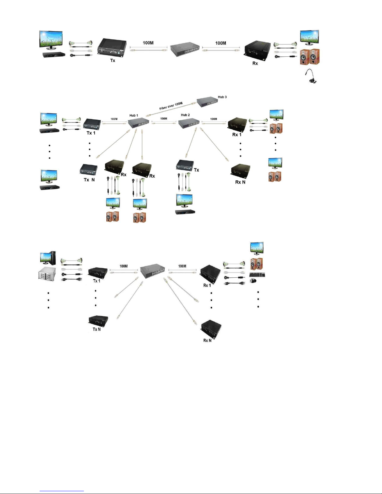
Point to Point With Switch Hub Connection: (Extender over LAN)
Multiple TX to Multiple RX via Switch Hub Connection
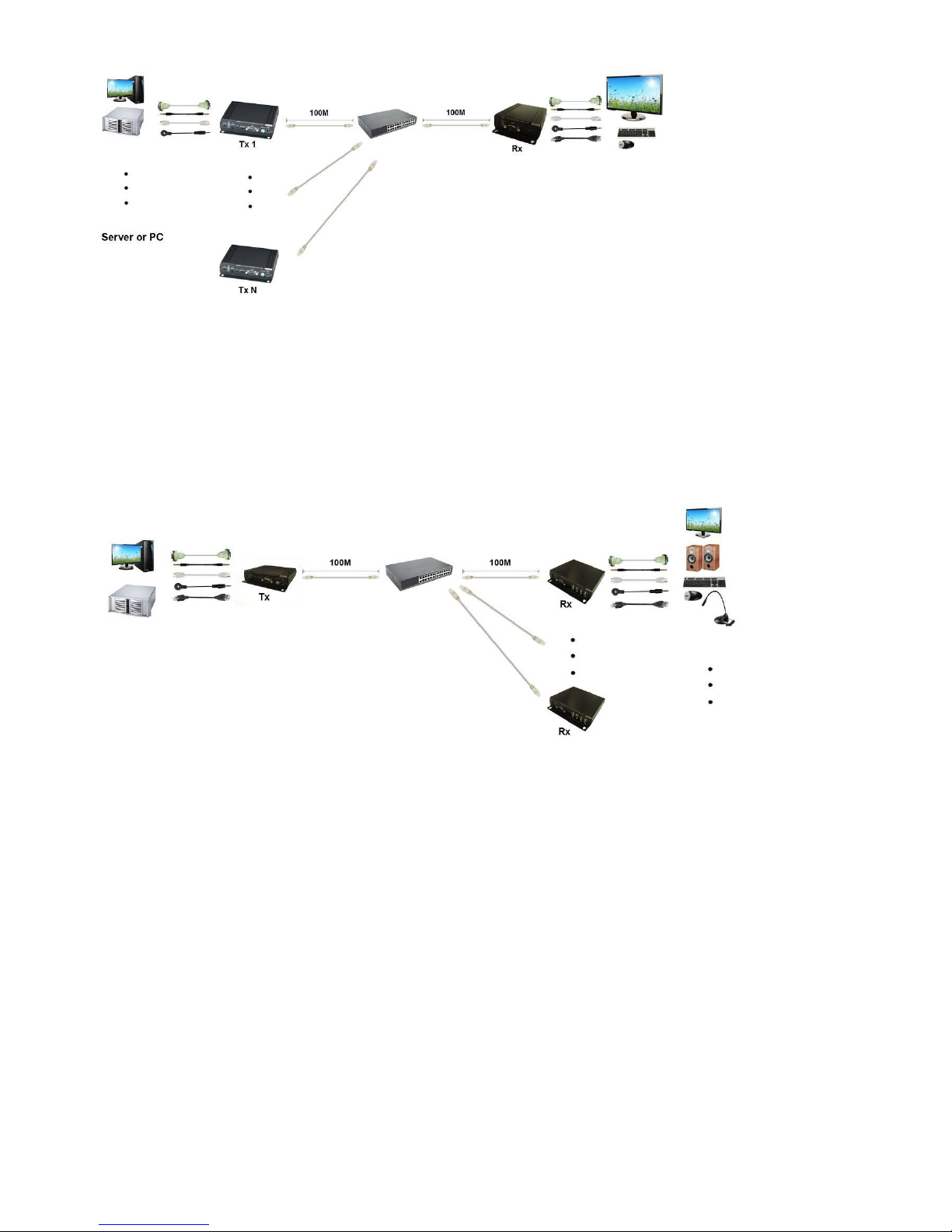
Multiple TX to Multiple RX Connection: (Matrix Switcher)
Multiple TX to One RX r Connection: (KVM Switcher over IP)
3
One TX to Multiple RX Connection: (Splitter)
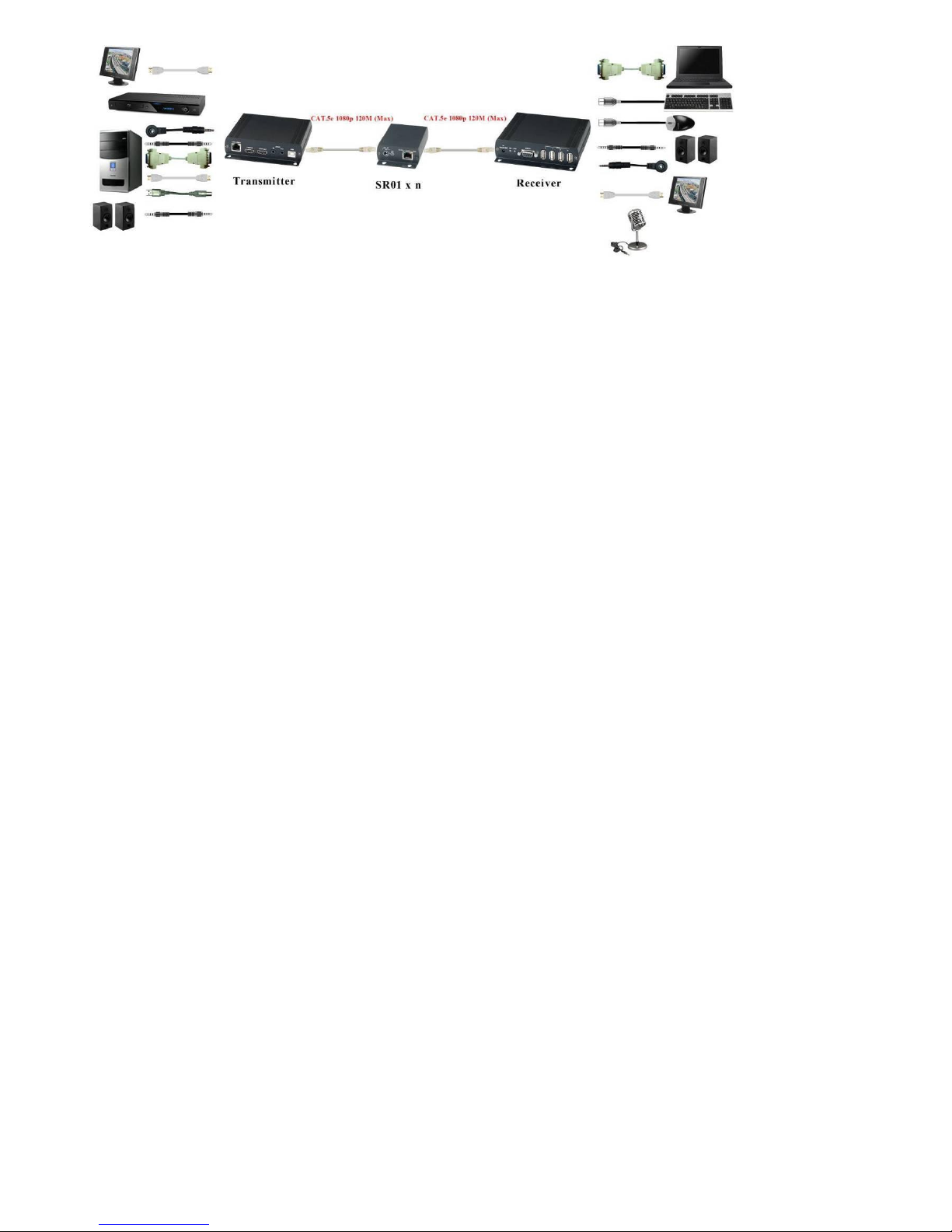
Optional Model: (order separately)
SR01 Signal Repeater
Extend data signal for an additional 120meters.
Application for DKM01B signals for extra long range transmission.
Ability to cascade connection with multiple SR01 for long range transmission
Built in LED status indication.
External power required.
Plug and play for easy installation.
4
5
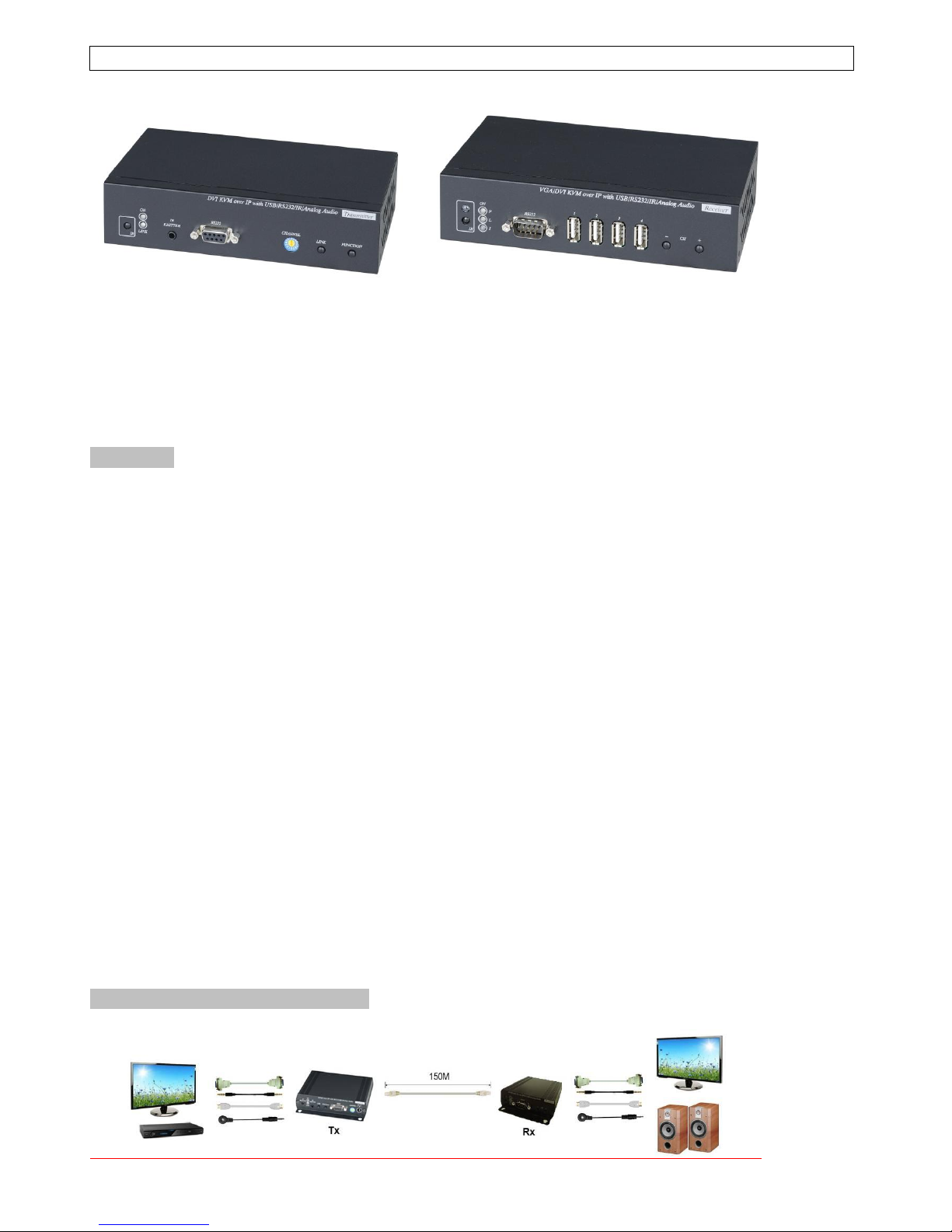
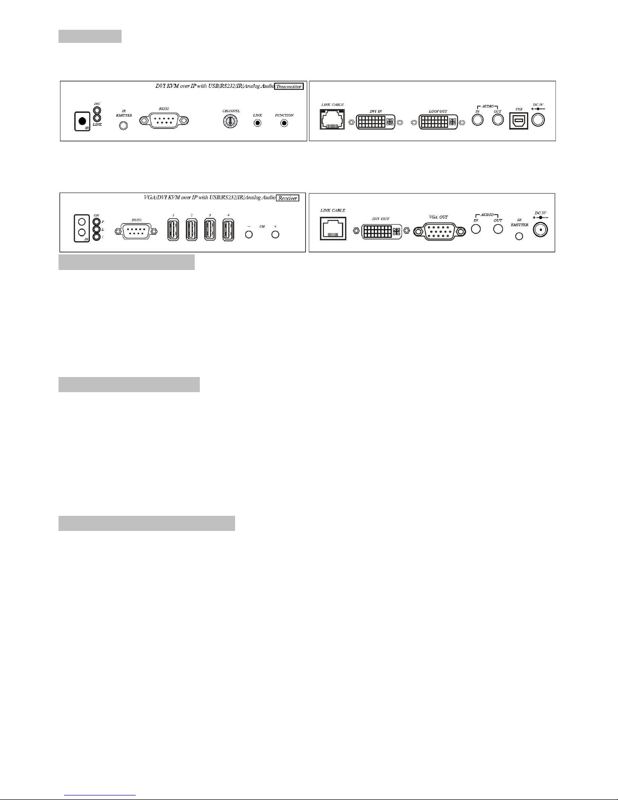
Panel View:
Transmitters
DKM01BT
Receivers
VDKM01BR
Video Output Setting:
VDKM01BR support both DVI and VGA output, default is DVI output only.
To change the output setting please press below button 5 seconds till power LED flash, it will
reboot automatically ( about 30 seconds to reboot).
[CH-]: VGA output only
[CH+]: DVI output only
[CH-] and [CH+]: DVI and VGA output both
Notice: in both mode the DVI monitor must be connected and power on.
LED Indication Status:
Power (Green LED): Flash Booting
ON Boot completed
Link (Blue LED): Flash Connecting or connected but no HDMI input
ON Transmitter connected with Receiver
Receiver IR (Red LED): On Received IR signal
Flash IR signal status / Enter IR learning mode
RJ45 LED Indication Status:
Green Flash Data transmission
Orange On Ethernet connected
6
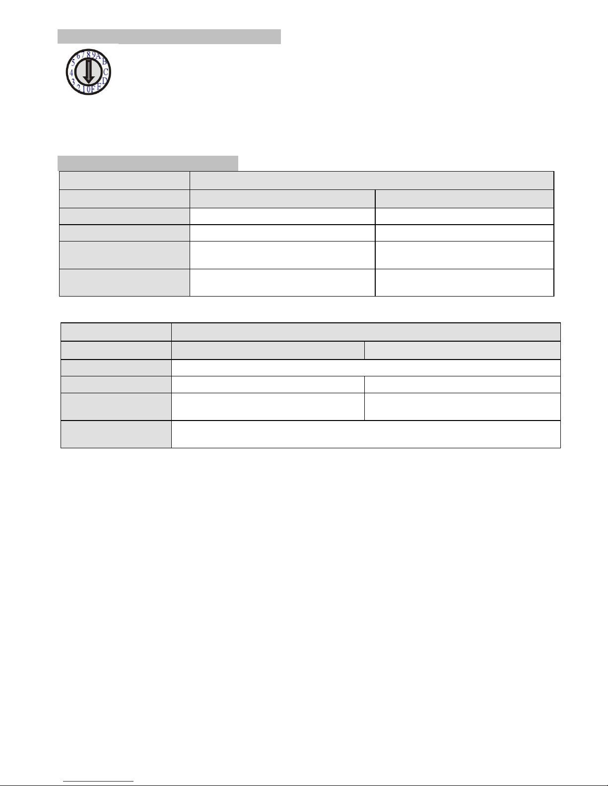
Back Panel Rotary Switch Function:
Transmitter and receiver must setting at same channel in order to do mutual transmission.
Rotary switch to be follow 16 HEX, could switch “ 0 ~ F “ total 16 channels, A = channel 10, B = channel 11,
others channel same as 16 hex conversion.
Transmitter channel setting must be unique to avoid conflict with any other transmitters.
Front Panel Button Function:
ITEM
TRANSMITTER
Button
LINK
FUNCTION
Short Press
Remote output (on / off)
Video Mode / Graphic Mode
Long Press (3 seconds)
Loop output (on / off)
Anti-Dither (1/2/off)
Press to power on (Hold until
Green LED Flash)
N/A
Update EDID from loop output
Press to power on (Hold until
Green and Blue LED Flash)
RESET to Default
N/A
Above “bold font” part as the default
ITEM
RECEIVER
Button
CH. -
CH. +
Press together
Confirm / Enter menu
Short Press
Reduce the numbers of Channel/Menu/Value
Increase the numbers of Channel/Menu/Value
Press 5 seconds
(VDKM01BR only)
VGA output only
DVI output only
Press 5 seconds together
(VDKM01BR only)
DVI and VGA output both
(DVI monitor must be connected and power on)
Above “bold font” part as the default

7
RJ45 pin define:
Link Cable (TIA/EIA-568-B)
1. Orange-white Data 1 +
2. Orange Data 1 -
3. Green-white Data 2 +
4. Blue Data 3 +
5. Blue-white Data 3 -
6. Green Data 2 -
7. Brown-white Data 4 +
8. Brown Data 4 -
Cable & Transmission Distance:
Link Cable use high quality Cat.5e UTP/STP/FTP or Cat.6 UTP cable
Transmission distance will be affected by equipment (Switch HUB), cable quality…etc. When
using CAT.5e the max. Transmission distance up to 150M, using CAT.6 cable up to 180M.
You can also use model no: SR01 repeater for extended longer distance or using Gigabit Switch
hub which support IGMP protocol and Jumbo Frame 8K for signal distribution or extend distance.
System Default Settings:
Transmitter / receiver support Unicast and Multicast two mode, default is Multicast.
In Multicast mode it could be one to one, one to multi, multi to on or multi to multi applications.
The analog audio output of transmitter and input of receiver will be off in this mode, analog audio
only from transmitters send to receivers.
Analog audio bi-direction transmission only in Unicast mode, please refer to the web setting
chapter: Casting Mode
System default IP setting is Auto IP, it will assign 169.254.X.X (submask 255.255.0.0) to
transmitters and receivers, you could also set to DHCP or Static IP, please refer to web setting
chapter: IP Setup.

8
Bandwidth Chart:
The bandwidth will be varied based on different resolution. Higher resolution may not request
bigger bandwidth. Below Chart is the resolution and bandwidth status for reference.
Resolution (@60Hz)
Average Bandwidth (Mbps)
1080p
77 (24 ~ 91)
720p
46 (29 ~ 150)
480p
63 (36 ~ 73)
1600x1200 (UXGA)
59 (24 ~ 73)
1280x1024 (SXGA)
58 (31 ~ 76)
1024x768 (XGA)
118 (56 ~ 138)
800x600 (SVGA)
83 (64 ~ 107)
System scalability is limited only by uplink and stacking connector bandwidths but can
accommodate up to 16 Full HD video sources at once.
For example under Gigabit Ethernet network, the total flow must not exceed 1000Mbps to avoid
any delay on video streaming. If the video play with 1080p resolution, the transmitter allow
maximum up to 10pcs for simultaneous video streaming.
Above bandwidth chart not include USB transmission, it cost up to 50 Mbps when transferring mass
data.
USB Hot Key Function:
In multicast mode support multi USB keyboard and mouse in each receivers, just plug and play, but
only one USB FLASH drive / hard disk could be used at same time.
You have to click “Pause/Break” key three times of the keyboard on the receiver to establish USB
FLASH drive /hard disk connection.

9
Remote Control Function:
If you do not use PC computer management to setup receiver, then you could use
the IR infrared remote control to preset channel selection. Using the IR remote
control to the front of receiver will be ok.
Initial at first time use the remote control or after change battery of remote control,
the IR remote control and the equipment Remote ID must be using same ID. The
default Remote ID is 8.
To setting the Remote ID, Press and hold power button, then press button 8 to
complete the setting. + .(for example)
Remote Control Button Function:
Symbol Function
Power Temporarily turn off the screen output /setup remote control Remote ID
MENU Menu selection, input numbers after press menu button
LEFT Previous channel
RIGHT Next channel
UP Previous quick Menu selection
DOWN Next quick Menu selection
ENTER Confirmation / display the current channel
1 Number 1
2 Number 2
3 Number 3
4 Number 4
5 Number 5
6 Number 6
7 Number 7
8 Number 8
9 Number 9
0 Number 0
* Cancel / exit
# Clear input number
A No function
B No function

10
Remote Control Operation:
Select Channel:
Mode 1: use or select channel, if no any action after 3 seconds then it is the select
channel or press immediately to confirm the input channel.
Mode 2: select the channel number and press to confirm the input channel.
Select Function:
Mode 1: use or select function, press to confirm.
Mode 2: press , then input function number as below , press to confirm.
Basic Menu Number:
0 MAC Address Display equipment MAC Address.
1 IP Address Display equipment IP Address
2 Host IP Address Display current connected Host IP Address
3 Enable advance menu Enable advance menu
4 Disable advance menu Disable advance menu
Advance Menu Number:
5 Device No Display device number
6 Group No Display group number
7 Party No Display party number
8 Remote ID Display current Remote ID setting
9 System Version Display system version
10 Restart Link Reconnect with Host
11 Stop Link Stop the connection with Host
12 Video or Graphic Mode Switch Host Video (default) or Graphic Mode
13 Anti-Dithering Switch Host Video Anti-Dithering define, default is off
15 Set Device No Set device number to 0~999
16 Set Group No Set group number to 0~99
17 Set Party No Set party number to 0~99
18, Set Remote ID Set Remote ID to 0~9
20 Enable Channel Button Enable Channel Button
21 Disable Channel Button Disable Channel Button
22 Enable IR Remote Enable IR Remote
23 Disable IR Remote Disable IR Remote
24 Enable IR Extender Enable IR Extender
25 Disable IR Extender Disable IR Extender
26 Enable RS-232 Assign Mode Enable RS-232 Assign Mode, auto reboot after setting
27 Disable RS-232 Assign Mode Disable RS-232 Assign Mode, auto reboot after setting
System Maintains Menu Number:
300 Force Update EDID of a Target Client Set host EDID from current monitor
333 Reset to Factory Default Reset to Factory Default
999 Reboot Restart the system

11
RS-232 Assign Mode:
System default setting of RS-232 is extender, the connection topology same as the channel
connection. RS232 ports of receivers only connect to the transmitter with same channel ID.
You could enable RS232 assign mode to fix the connection of RS232 without channel setting.
After the receivers and transmitter you want to keep RS232 connection established then press IR
remote button to enable RS-232 assign mode.
If IP address of transmitter has been changed you have to enable RS232 assign mode for recovers
again.
To disable RS232 assign mode press IR remote button
RS-232 Control command:
User could use RS-232 port of transmitters at baud rate 115200bps (8-N-1) to operate/setup the
receivers at same channel
Command format: >CMD_Address> Command Parameters
All accord receivers will run the command and parameters, we also add 3 kinds of user defined
numbers except MAC & IP (Device No、Group No、Party No) for flexible application:
Mxxxx The last 4 digits of MAC Address e.g.: 221868860123 = M0123
Ixxxx The last 2 column of IP Address (HEX) e.g.: 169.254.012.034 = I0C22
Dxxxx Device No e.g.: Device No 1234 = D1234
Gxx Group No e.g.: Group No 12 = G12
Pxx Party No e.g.: Party No 34 = P34
CHx Channel No (HEX) e.g.: Channel 12 = CHC
ALL All receivers
Response format: <ACK_Address< Response character
Receivers will response message to transmitter as above format, if multiple receivers operate at
the same time they will not response to the transmitter by default.
To enforce response function please add “!” before commands and receivers will respond in
sequence by device number X 15ms.
Command and Parameters List:
Command
Function
Parameters
Response
CHANNEL
Select Channel
0 ~ 15 (Channel No.)
? (display setting)
OK = Setting successful
ERROR = Setting fail
REMOTE_ID
Set Remote ID
0-9 (Remote ID No.)
? (display Remote ID
No.)
OK = Setting successful
ERROR = Setting fail
BUTTON
Set button
ON
OFF
? (display setting)
OK = Setting successful
ERROR = Setting fail
IR_REMOTE
Set IR remote
ON
OFF
? (display setting)
OK = Setting successful
ERROR = Setting fail
IR_EXTENDER
Set IR Extender
ON
OFF
? (display setting)
OK = Setting successful
ERROR = Setting fail
DEVICE
Set Device Number
0 ~ 9999 (Device No.)
? (display setting)
OK = Setting successful
ERROR = Setting fail
GROUP
Set Group Number
0 ~ 99 (Group No.)
? (display setting)
OK = Setting successful
ERROR = Setting fail

12
PARTY
Set Party Number
0 ~ 99 (Party No.)
? (display setting)
OK = Setting successful
ERROR = Setting fail
OSD_ON
Display character on
screen 60 seconds
Character (alphabet
and numbers)
OK = Setting successful
ERROR = Setting fail
OSD_OFF
Turn off the OSD
0 ~ 60000 (Delay
time , based on ms)
OK = Setting successful
ERROR = Setting fail
SCREEN
Turn on/off screen
ON
OFF
OK = Setting successful
ERROR = Setting fail
REBOOT
System reboot
N/A
SYSTEM REBOOT
※ The maximum of OSD_ON is 30 characters, not support comma sign「,」, some characters must use \x##
format to display, ## means the characters number in ASCII 16 code
e.g.: \x0a is change to next line, \x28 is ( brackets sign, \x22 is “ sign
e.g.:
>CMD_M1234> CHANNEL 12 ( Set receivers which last 4 digits MAC Address is 1234 to Channel 12 )
<ACK_M1234< OK (Receiver which last 4 digits MAC Address is 1234 response OK)
>CMD_D123> BUTTON OFF (Turn off the button function of the receiver which Device number is 123)
<ACK_D123< OK (Receiver which Device number is 123 response OK)
>CMD_P5> !IR_KEY 31 All receivers which Party number is 5 send IR Key 31 and response.
<ACK_M0219< OK Receiver which last 4 digits MAC Address is 0129 response OK
<ACK_M021B< NO LEARN Receiver which last 4 digits MAC Address is 021B response NO LEARN
>CMD_ALL> !OSD_ON Hello! \x28123\x29 \x22ABC\x22 Show「Hello! (123) “ABC”」to all monitor and
send response
<ACK_M0219< OK Receiver which last 4 digits MAC Address is 0129 response OK
<ACK_M021B< OK Receiver which last 4 digits MAC Address is 021B response OK
<ACK_M021C< OK Receiver which last 4 digits MAC Address is 021C response OK
>CMD_ALL> OSD_OFF 10000 All receiver turn off OSD after 10 seconds

13
Caution:
1. Not recommend to work with general LAN connection to avoid large video, data transmission or multicast
packets to slow down your other LAN devices.
2. Gigabit switch hub muse use support IGMP protocol and Jumbo Frame over 8K Ethernet Switch Hub in
order to achieve the best transmission quality
3. If monitor shows green screen or video not smooth, please check if the switch running under gigabit and
Jumbo Frame function enabled.
4. Using computer or mobile APP management the IP address should be set in same network segment.
5. Computer software operation, please refer to software operating instruction.

14
Web Setting Function:
Transmitter/receiver provide detail settings over web browser, you have to know the IP address
before setting.
There are three ways to get the IP address of receiver:
1.Local IP shows on right bottom screen when booting.
2.Press remote control button (IP Address)
3.Install Internet explorer plug-in: Bonjour , click device name to enter web setting page to get the
IP address(please refer software installations manual)
There are two ways to get the IP address of transmitter:
1.Connect a transmitter and receiver and set in the same channel, press remote control button
at receiver side (Host IP Address), it will shows the transmitter IP Address on
screen(must remove the HDMI cable of transmitter or turn off the video source).
2. Install Internet explorer plug-in: Bonjour , click device name to enter web setting page to get the
IP address(please refer Bonjour plug-in installation)
System default IP setting is Auto IP, it will assign 169.254.X.X (subnet mask 255.255.0.0) to
transmitters and receivers, you could also set to DHCP or Static IP.
You computer must set in same subnet mask to enter the web setup page.
If you do not sure the IP address of transmitters/receivers you could reset the transmitters and
receiver to default.
For transmitters: press the LINK button to power on (Press and hold until Green and Blue LED
Flash) to reset to default.
For receivers: press remote control to reset to default.

15
Bonjour plug-in installation:
a. Click “BonjourSDKSetup.exe” to install Bonjour plug-in for Internet Explorer.
b. Click “Next” to continue.
c. Click “I accept the terms in the license agreement” to continue.
d. Click “Next” to continue.

16
e. Click “Install” to start installation.
f. Click “Finish” to exit installation.
g. Right click on “My Network Place” “Properties” then right click on “Local Area Connection”
“Properties” then double click on “Internet Protocol (TCP/IP)” to setting as below:
(IP address 169.254.111.111, sub mask 255.255.0.0)

17
Login in to the web setting:
Use CAT5 cable to connect transmitter/receiver RJ45 port to PC LAN port, open IE browser then
select View Explorer Bars Bonjour.
Double click on “HTTP on ast-gateway(transmitter)” or “HTTP on ast-client (receiver)”, it will pop up
web setup in Bonjour windows as below:
Click Network page you will see the IP address of transmitter/receiver
You could also input the IP address of transmitter / receiver at link column of browser if you know
the exact IP address of them.

18
System Menu:
Version Information Firmware version information
Update Firmware Update system firmware
Utilities System tools
Factory Default Set system to factory default
Reboot Reboot system
Default EDID Set EDID to default
Console API Command Run Console API command
Statistics System status

19
Network Menu:
IP Setup:
IP Mode could be Auto IP, DHCP, Static three mode, default is Auto IP
Casting Mode : could be Multicast, Unicast mode, default is Multicast,
When using Multicast mode, please check the “Auto select USB operation mode per casting
mode” box

20
Functions Menu:
For transmitter:
Video over IP:
This function setup the video signals send from network, default is checked.
Please note it will turn off HDMI output of receivers in same channel if this function be
disabled, only analog audio output
For Receiver:
Video over IP:
This function setup the video signals send from network, default is checked.
Please note it will turn off HDMI output of receiver if this function be disabled, only analog
audio output
Copy EDID from this Video Output:
Check this box will auto copy EDID from the TV connected to receiver when receiver booting,
default is not checked.
In multiple connections transmitter will use default EDID 1080p with 2 channel audio, to
prevent EDID conflict recommend check this box in Unicast mode only.

21
USB over IP Setup:
This function setup the USB signals send from network, default is checked.
Operation Mode:
USB device operation setting, default is “Auto select mode”
In Unicast mode recommend set to “Active on link”.
In Multicast mode recommend set to “Active per request”.

22
Serial over IP:
This function setup Serial (RS232) signal sends from network
Operation Mode:
Default is “Type 2 (Recommended. Dumb redirection.)”
Baudrate Setting for Type 2 : default is 115200, 8, None, 1

23
DKM01BT Package Include:
Transmitter x 1
USB A to B cable x 1
IR emitter cable x 1
DC 5V 2Amp power adapter x 1
Software CD x1
VDKM01BR Package Include:
Receiver x 1
IR emitter cable x 1
IR remote control x1
DC 5V 2Amp power adapter x 1
Specification:
ITEM NO.
DKM01BT
Support Resolution
480i / 480p / 720p / 1080i / 1080p @ 24Hz、25Hz、30Hz、50Hz、60Hz
Transmission Distance
CAT.5e:150M / CAT.6:180M (Max)
USB Connector
USB Type B x 1
RS232 Connector
DB9 (Female) x 1
Video Input Connector
DVI-I x 1 (29 Pin) Digital Only
Video Loop Output
Connector
DVI-I x 1 (29 Pin) Digital Only
Link Connector
RJ45 x 1
Audio Connector
3.5 mm Phone Jack x 2 (10KΩ / 1Vpp)
IR Receiver (Internal)
30-60Khz / ±45° / 5M
IR Emitter (External)
3.5mm Stereo Phone Jack
Power Supply
DC 5V 2A
Power Consumption
750mA (Typical) / 1000mA (Max)
Temperature
Operation: 0 to 55℃, Storage: -20 TO 85℃, Humidity: up to 95%
Dimensions mm
167x105.5x40
Weight g
470
ITEM NO.
VDKM01BR
Support Resolution
480i / 480p / 720p / 1080i / 1080p @ 24Hz、25Hz、30Hz、50Hz、60Hz
Transmission Distance
CAT.5e:150M / CAT.6:180M (Max)
USB Connector
USB Type A x 4
RS232 Connector
DB9 (Male) x 1
Video Output Connector
DVI-I x 1 (29 Pin) Digital Only /15-pin Mini D-sub
Link Connector
RJ45 x 1
Audio Connector
3.5 mm Phone Jack x 2 (10KΩ / 1Vpp)
IR Receiver (Internal)
30-60Khz / ±45° / 5M
IR Emitter (External)
3.5mm Stereo Phone Jack
Power Supply
DC 5V 2A
Power Consumption
750mA (Typical) / 1000mA (Max) Without USB Power Consumption
Temperature
Operation: 0 to 55℃, Storage: -20 TO 85℃, Humidity: up to 95%
Dimensions mm
167x105.5x40
Weight g
480
Rev. A
 Loading...