

Page 1
DVR Server Manual ver.5.05/rel.092507
I
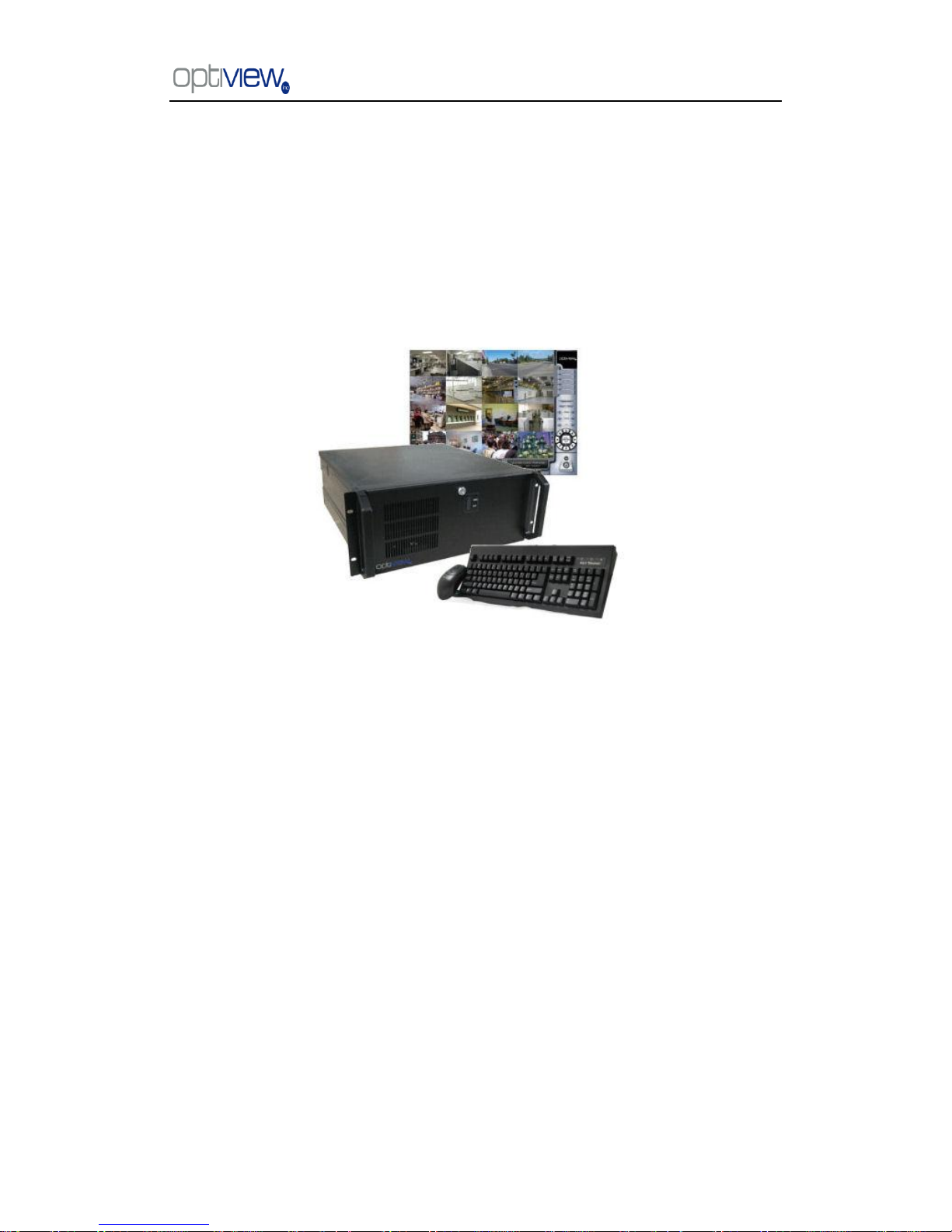
VR Enterprise DVR System
DVR Server (ver.5.05)
User Manual
Page 2

DVR Server Manual ver.5.05/rel.092507
II
Contents
Chapter1 Start up and Main Interface ··························································· 2
1.1 Start up ····················································································································· 2
1.2 Main Interface ·········································································································· 2
1.2.1 Show tips ··············································································································· 2
1.2.2 Screen menu ·········································································································· 2
1.2.3 Interface description ····························································································· 5
1.2.4 System Menu ········································································································· 7
1.2.5 Network panel ····································································································· 13
1.2.6 PTZ Control panel ······························································································ 14
1.2.7 Color and Audio adjustment ··············································································· 17
1.2.8 Matrix & display ································································································· 17
1.2.9 DI/DO Control ···································································································· 18
Chapter2 Local setup ·················································································· 19
2.1 System setup ·········································································································· 20
2.1.1 System setup ········································································································ 20
2.1.2 Network setup ······································································································ 21
2.1.3 Boot setup ············································································································ 23
2.2 Camera setup ·········································································································· 24
2.2.1 Camera setup ······································································································ 24
2.2.2 Group setup ········································································································· 27
2.3 Sensor setup ··········································································································· 29
2.3.1 Sensor setup ········································································································ 29
2.3.2 Group setup ········································································································· 29
2.4 PTZ & Linkage setup ····························································································· 31
2.4.1 PTZ protocol setup ······························································································ 31
2.4.2 Motion detection relay & remote client alert ······················································ 31
2.5 E-mail setup ··········································································································· 33
2.5.1 SMTP setup ········································································································· 33
2.5.2 E-Mail setup ········································································································ 34
2.6 Digital matrix setup ································································································ 34
2.6.1 Matrix setup ········································································································ 34
2.6.2 Display setup ······································································································· 35
2.7 User setup ··············································································································· 36
2.7.1 User information ································································································· 36
2.7.2 User right setup ··································································································· 37
Page 3

DVR Server Manual ver.5.05/rel.092507
III
Chapter3 IP Camera Setup ·········································································· 38
3.1 Functional buttons ·································································································· 38
3.2 Server setup ············································································································ 39
3.3 Channel setup ········································································································· 40
3.3 PTZ Control Setup ································································································· 41
3.4 Channel setup ········································································································· 42
3.5 Sensor setup ··········································································································· 43
3.6 Alarm setup ············································································································ 45
Chapter4 Local playback ············································································· 46
4.1 Main interface ········································································································ 46
4.2 Select playback channel ························································································· 46
4.3 Play file and related operations ·············································································· 47
4.4 Capture picture ······································································································· 49
4.5 Create clip file ········································································································ 49
4.5.1 Create file clip ····································································································· 49
4.5.2 Backup by time: ··································································································· 50
4.5.3 View Backup file ·································································································· 52
4.6 Search captured picture ·························································································· 54
4.7 Fast search ·············································································································· 55
4.8 Camera status ········································································································· 55
4.9 Show files ··············································································································· 57
Chapter 5 IE client ························································································ 59
5.1 Functions of IE Client ···························································································· 59
5.2 Main interface ········································································································ 59
5.2.1 Connection operations ························································································ 59
5.2.2 Connection/Record status ··················································································· 60
5.2.3 Partition mode ···································································································· 60
5.2.4 PTZ Control ········································································································ 60
5.2.5 Quit program ······································································································· 60
5.3 Local search ··········································································································· 61
5.4 Remote search ········································································································ 62
5.4.1 Fast download record data ················································································· 62
Chapter6 Mobile Client ················································································ 64
Page 4

DVR Server Manual ver.5.05/rel.092507
IV
Chapter7 Appendixes ·················································································· 68
7.1 Appendix A: Fast key reference ············································································· 68
7.2 Appendix B: Audio preview ··················································································· 69
7.3 Appendix C: Update drivers of compressed card ·················································· 70
7.4 Appendix D: How to use “Copy File” folder. ························································ 71
7.5 Appendix F: Frequent Asked Questions ································································ 72
7.6 View the DVR via Internet····················································································· 74
7.7 How to turn ON Automatic Windows Login ························································· 76
7.8 DVR System Recovery Procedure ········································································· 78
Refer to the Tutorial video for other selected topic illustrated in video format.
The tutorials are small video file that can be played from the local DVR system.
It will illustrate many of the common task involved in working with your DVR system.
Please follow the link from the desktop ―Click here for Technical Support and Serial number‖.
Page 5

DVR Server Manual ver.5.05/rel.092507
1
Thank you for purchasing VR Enterprise series DVR system. This User manual is designed to
inform you how to setup the DVR system and explain each function for you to make the most out of
the system professionally and meet your security recording needs.
IMPORTANT! Operators of the VR Enterprise series DVR system must thoroughly read this
manual prior to using the system.
VR Enterprise Series: DVR System Overview
The VR Enterprise series DVR system is fully designed with flexibility, reliability and
performance. This DVR system gives you greater option to customize the system settings.
You have the leverage and flexibility on the DVR depending on your specific Digital Video Recoding
requirements.
Cost Efficient – Uses IP infrastructure, so there is no need for costly dedicated cables
between sites and servers and manage the data, videos, audio, and other files efficiently. Uses
H.264 technology, which maximizes the use of the space on your HDD.
Leverage - Centralize control of setup parameters, scheduled alerts and maintenance of those
individual digital image devices like DVR, DVS, etc.
Straightforward Application and Management - Supports centralized network recording
management, flexible storage and HDD coverage and usage. Password-protected application
with multi-level user rights assignment per user.
System Features
Hardware support for H.264 compression, therefore giving you low HDD cost and excellent
video quality
Remote access via Internet web browser or through client software.
Computer Network support with High speed Internet.
connection is highly recommended.
Real-time, full-motion video capture & display (Max. 48 channel video input)
Real-time high-speed recording: Max. 30 frames/sec per channel
Synchronous audio recording (optional)
Motion detect (Whole area or max. 12 detection zones per channel)
Normal continuous recording and event recording (Motion detection or Optional external
sensor)
Electronic Map pop-up when there is an alarm event (optional)
System operation and alarm logging
Alarm-before recording, Auto send an alarm message
Remote recording
Alarm image auto send to email box as attachment
Matrix display and group display
Pan, tilt, zoom, focus & speed dome control
Search/playback by date/time directory (random-access), Duplex mode (Recording while
playback)
Page 6
DVR Server Manual ver.5.05/rel.092507
2
Chapter1 Start up and Main Interface
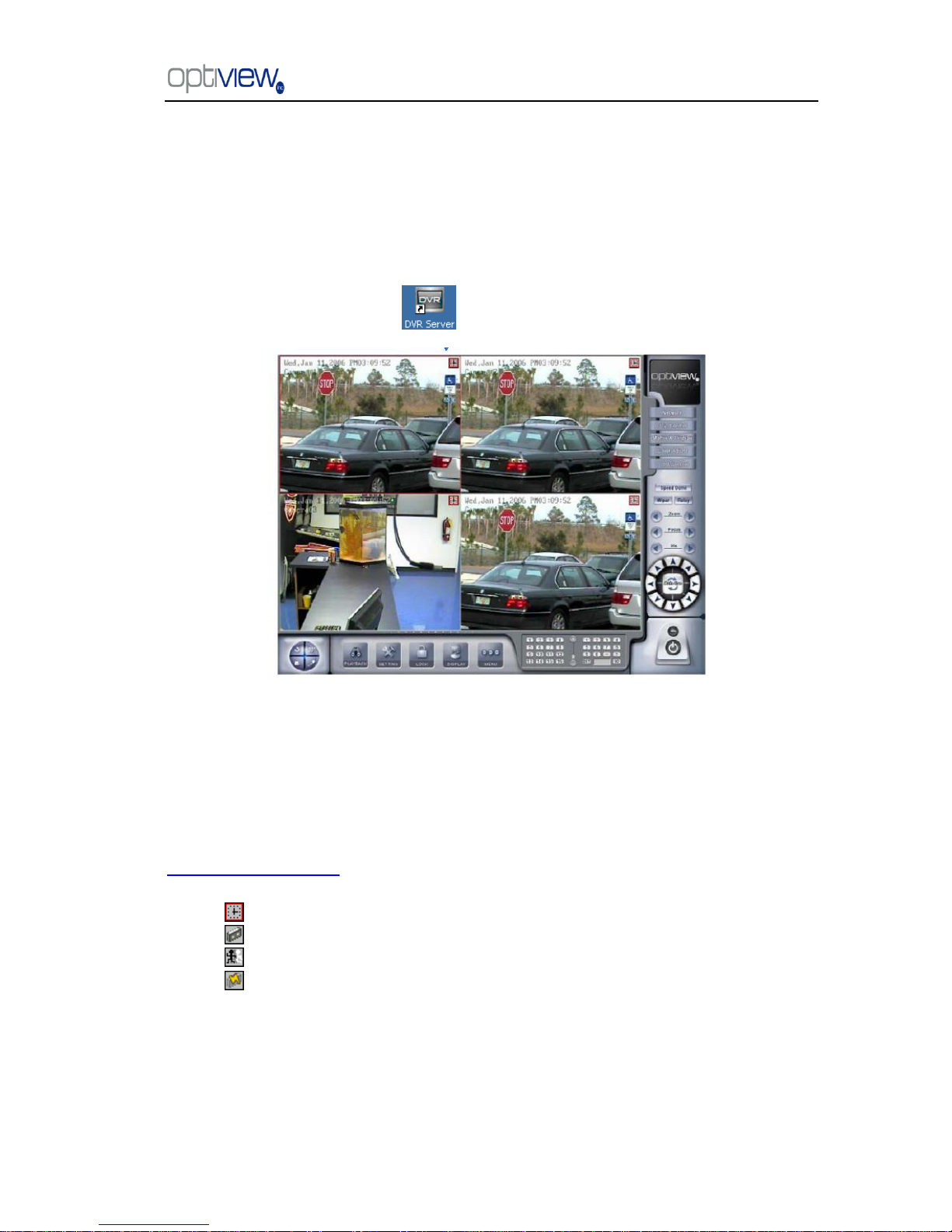
1.1 Start up
1).Before you run the DVR server, please make sure all devices are firmly connected.
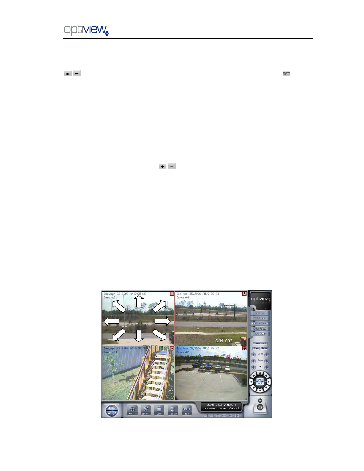
Left-Double-Click shortcut icon to start it. The main interface is as follows:
1.2 Main Interface
1.2.1 Show tips
1. When the mouse moves closely or stops above a button, a text tip will be shown to interpret
its function.
2. Zoom in/out video image: Left-Double-Click a camera window to zoom in/out video image (or
press F11 on the keyboard).
3. Recording status: (an icon found at the top right corner of the video screen)
a. This icon means the system is recording normally.
b. This icon means the system is recording manually.
c. This icon means the system is recording in motion detection.
d. This icon means the system is recording in sensor detection.
1.2.2 Screen menu
Press TAB key or Page UP (select next camera window) and Page Down (select previous
camera window) key on keyboard to select one live camera window.
Page 7
DVR Server Manual ver.5.05/rel.092507
3
1. Full screen
Single-Right- Click image area, it will popup a menu, then select ―full screen‖ to change the
display mode to full screen (or press F12 on the keyboard). When you want to resume normal mode,
you should Single-Right- Click image area and select ―Restore display‖.
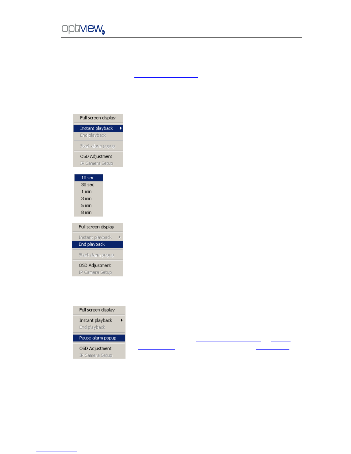
2. Instant playback
3. Alarm popup
Single-Right-Click desired camera window and select
―Instant playback‖. However, IP Camera‘s instant playback can
only be done doing a right click on a currently unused video
display window.
A submenu will be shown for you to choose a preset length
of time of instant playback .
The window that is playing back video data will indicate a
yellow border to be different from the live windows.
In the course of the instant playback, you can press Space
key to switch the play/pause status or direction key → and ←
to play next and previous frame.
If you want to stop the instant playback, you can
Single-Right-Click the play backing window, and select ―End
playback‖.
First, enable ―Alarm camera pop-up interval‖ in System Setup‖
menu by selecting the time interval in seconds. Single-Right-Click
video image area at the main interface and select ―Start alarm
popup‖. After setting up all these configurations, when there is a
motion detection alarm (set in PTZ & Linkage setup and Motion
detection setup) or an alarm triggered by sensor (set in Sensor
setup), system will display alarm cameras in sequence. When you
want to end this function, you can Single-Right-Click video image
area and select ―Pause alarm popup‖. (This functionality does not
apply IP camera through the IP Video Server, even IP camera have
alarms, their images will not pop up).
Page 8
DVR Server Manual ver.5.05/rel.092507
4
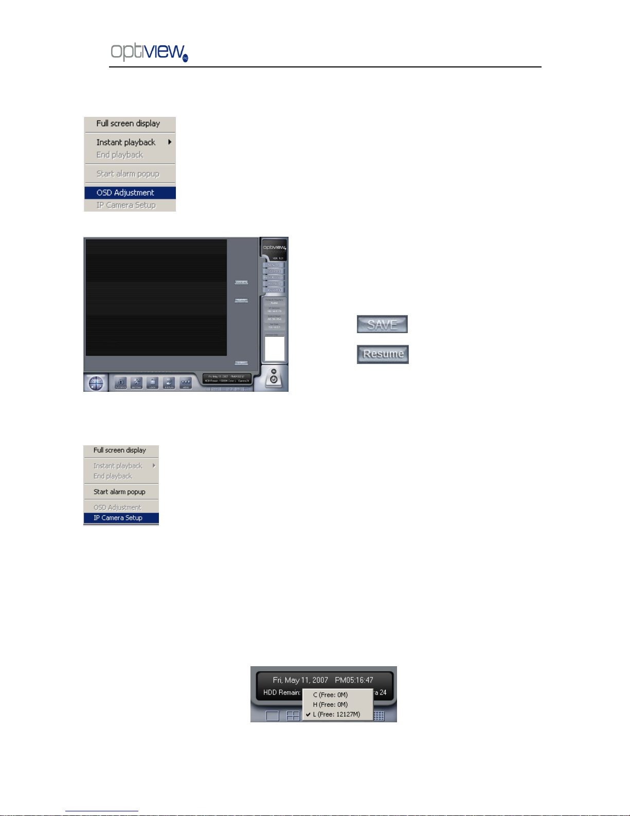
4. OSD Adjustment
5. IP Camera setup
6. Change record disk
From the information display panel you can see the current recording disk, and when you Single-Click
the corresponding panel, it will show the available disk with its total free spaces. Also you can change
the recording disk by selecting the disk directly. The system will check the disk per 10s, and it is
recommended that you change the recording disk to local disk when system is writing data into
removable disk before you remove it.
When the capacity of HDD is not enough or there has been some errors while recording, the
Single-Right-Click video image area in main interface and select ―OSD
Adjustment‖ to adjust the position of OSD (IP Camera does not have this
function; you can set the OSD position in IP Camera setup remotely).
OSD includes time and channel name.
In this screen you can press time or
channel name and drag them to where you
want directly, after that, you can press
button to save and press
button to resume time and
channel name to default position.
This function is only available when you Right-single-Click an image of
IP camera Other information will be discussed in IP Camera Setup.
Page 9
DVR Server Manual ver.5.05/rel.092507
5
DVR system will pop up information to inform you of the failure of recording and the corresponding
camera will stop recording.
1.2.3 Interface description
1. Partition mode
button to set the window‘s partition mode of the main screen. There are many types of
partitions. The available partition is determined by the total channels of the card. You can select
the suitable partition according to the number of video inputs; the partition number which is
bigger than total channel is not available with gray.
2. Videos-play-in-sequence mode switch
Press button to switch between playing all cameras in current windows in sequence and
not when the current partition number is smaller than the total channels of the card.
3. Emergency recording button
Press button to trigger recording of all cameras for 30 seconds even if they have
been set to record by any other modes. This function is useful to deal with emergency
situation where quick response is required.
4. Image capture
Press button to save a still image of selected camera to local hard disk for
reviewing or print.
5. Manual record switch
Press button to record manually and press it again to stop manual recording for
selected camera.
6. Information display panel
This panel shows day of the week, current date, current time, total free hard disk space, current
Page 10
DVR Server Manual ver.5.05/rel.092507
6
record disk and description of selected camera.
7. Local setup submenu
Press button to enter Local setup submenu.
8. Local playback submenu
Press button to enter Local playback submenu to search local video/audio data.
9. System lock
Press button to prevent unauthorized user to operate system. Press this button
again; the unlock dialog box will be displayed. Input your User ID and password then press OK to
unlock it.
Default User ID is ―admin‖, with no password.
Note: If the DVR system is not configured as User Manage Mode ( Use Password is disabled) , the lock
button will be unusable and will allow any client access
10. Minimize button
Press button to minimize the main window (or press WIN + Z on keyboard).
Page 11
DVR Server Manual ver.5.05/rel.092507
7
11. Exit program
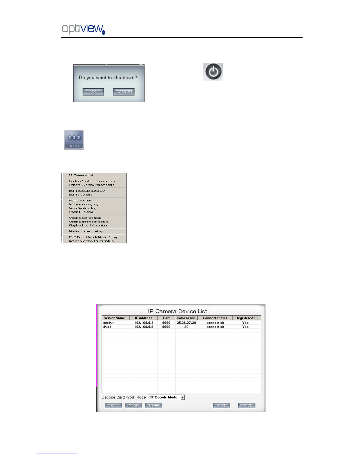
1.2.4 System Menu
opens up your option to go to other features menu such as remote voice chat,
Windows Explorer, electronic map, write working log, view system log and motion setup as shown
below:
1.2.4.1 IP Camera Device List
Press this bar to add an IP Module to the DVR system. For resource limitation, you can add
max 16 IP Modules, including Digital video Server (DVS). However, each device can only add
one channel to the DVR system.
Press button to exit program.
After clicking this button, a dialog will display.
Click ―OK‖ to quit DVR system.
Page 12
DVR Server Manual ver.5.05/rel.092507
8
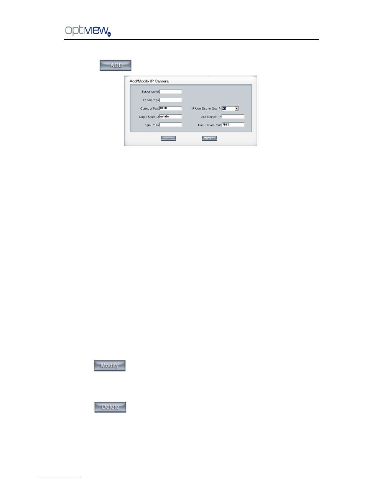
1.2.4.1.1 Add IP camera device
Press button to add an IP Camera device:
Figure2— 1
【Server Name】Set a name for the new IP camera device.
【IP Address】Input the address of the IP Camera, it is an IP address or IP alias of an IP camera
which is connected through DNS Server.
【Connect Port】Set the port through which connects to IP Camera.
【Login user ID/Login Pass】When the user wants to visit IP Camera and the server has used
the function of rights management, login user ID and password will be checked. If the user has no
rights to visit that camera, the connection will be shut down automatically.
【Using DNS to get IP】Select whether to use DNS to get IP or not, if the server end is the
dynamic IP address, users need to use the DNS to get the server‘s IP.
【DNS Server IP】Set IP address of DNS server host.
【DNS Server Port】DNS server host‘s port, which is provided to connect DNS software.
Note:
1. Currently our DVR server allows a maximum of 16 channels for IP cameras. For each device, the system allows you to
connect a maximum of 4 cameras.
2. After you add IP cameras to the DVR system, they will be assigned sequence numbers followed on local board cards.
The sequence numbers of the IP camera change dynamically according to the total numbers of local board cards and the
sequences of the IP cameras to be added. For example, if there are 32 channels local board card, and you add 2 IP cameras,
they will be assigned 33 and 34 as their sequence number. Then if you add another board card (4 channels), the sequence
number of them will change to 37and 38 dynamically.
1.2 .4.1.2 Modify IP Camera
Press button to modify/edit the IP camera‘s information.
1.2.4.1.3 Delete IP camera device
Press button to delete connected server. When system is in processing to add IP
camera device (―connecting…‖indicated in connect status column), user can not delete that IP
camera device.
Page 13

DVR Server Manual ver.5.05/rel.092507
9
1.2.4.1.4 Decode card work mode
DVR system supports playing video of IP Camera to TV wall directly, then it uses the hard
decoding function of decoder, so you should set the work mode of decoder. If you don‘t use hard
decoding, you can‘t output video of IP Camera real-time, user can only play back recording data to
TV monitor by selecting Playback to TV Wall function.
Note:
Each NV4002MD card can decode 2 channels D1 or 4channels CIF.
Each NV4004MD card can decode 4 channels D1 or 8 channels CIF.
When you select the work mode, system will send out corresponding channels of IP camera
from the first IP camera. It will not influence soft decoding for cameras of local board cards.
2. Backup System Parameters
Select this function to export system configurations.
3. Import System Parameters
Select this function to import system configurations.
4. Burn backup data CD
Select this function to burn video data to CD, it is same to burn CD function in Local Playback.
5. Burn DVD disc
Burn DVD disc by invoking other professional burning software.
6. Remote chat
Select this function to connect a remote Client or Server for a live chatting via IP address. You
must have an audio card and Microphone installed in each PC.
7. Write working log
This is useful to record events that occur during the operator‘s shift.
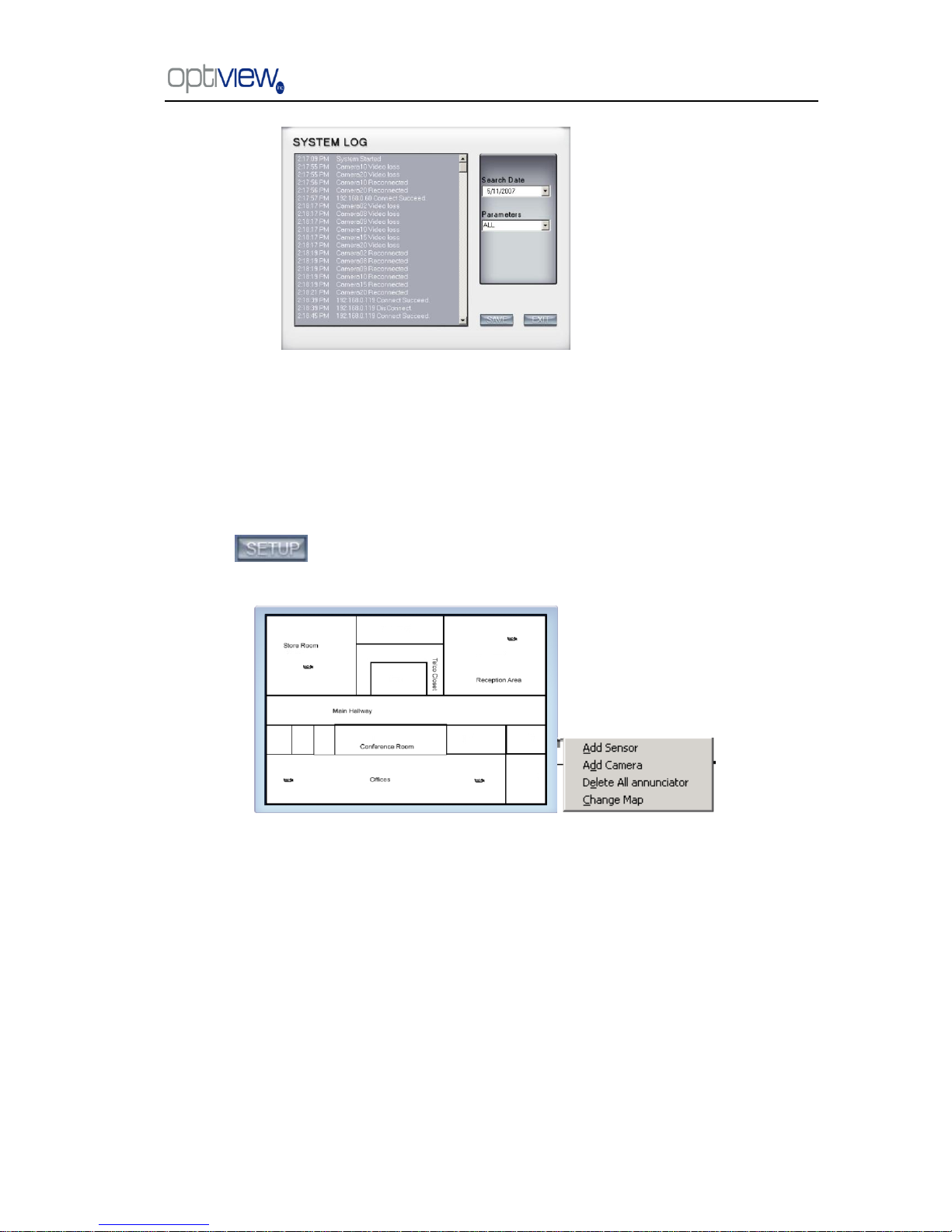
8. View System log
Select this function to view all actions of recording as well as operations. System log keeps a
record of system events such as program startup and shutdown, changing camera setup and all
operator or system daily activities sorted according to time and date. Users can view log by date and
system parameters. System parameter includes operations, system prompts, alarms and other
activities.
Page 14
DVR Server Manual ver.5.05/rel.092507
10
9. Open Explorer
When keyboard is locked, Users can operate window resource via explorer.
10. Open electronic map
Select this function to set E-map,
Click icon and then Right-Single-Click on the map, the setting picture will appear.
You can add or delete sensors and cameras that are pointed by the arrow or change the digital map.
If it is set to appear automatically, when the sensor is triggered, the map will appear
automatically and the sensor being triggered will be marked. For triggered camera, user can
Left-Double-Click it to view its video.
11. Open Screen Keyboard
This function allows the user to use soft keyboard, you can press this bar to open the screen
keyboard. Also, in the setup interface you can Left-Double-Click the blank to open this keyboard.
User can close this keyboard manually.
Page 15
DVR Server Manual ver.5.05/rel.092507
11
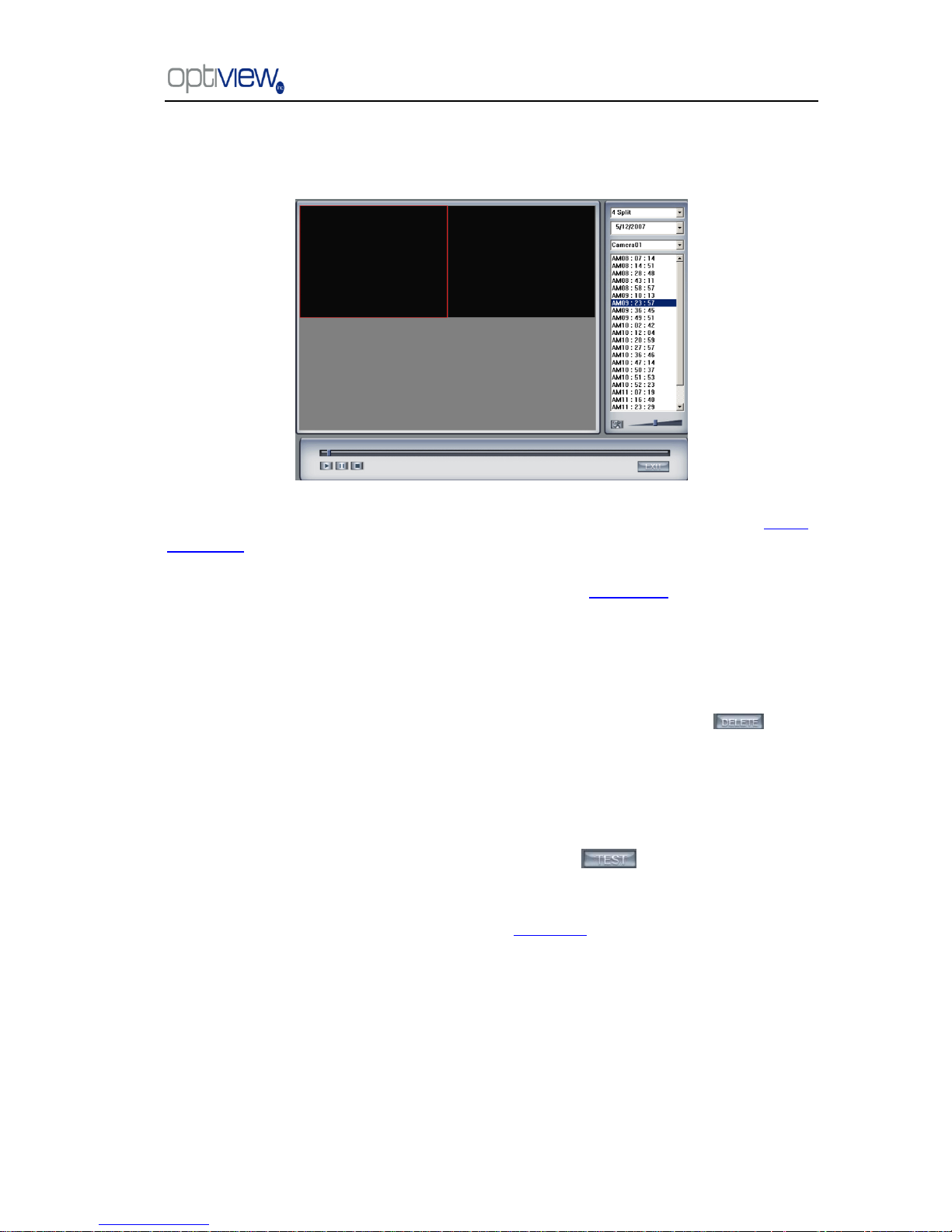
12. Play back to TV monitor
In DVR system, the recording data can be transmitted to TV monitor via Matrix card.
When system runs the ―Playback to TV Wall‖ process, the Matrix card will output recording data.
If this process does not run, matrix decode card will output real-time video according to your matrix
board setup. Otherwise, when you use matrix card to decode video data from IP Camera, you can‘t
use this function to play back recording video data to TV Monitor but only output real-time video of
local board and IP Camera to TV Wall according to you setting in Matrix setup. In this process, you
can play back record file by date and camera, and the record file will be played automatically.
13. Motion Detect setup
By default, the entire screen is set as motion detection area where it is indicated with green
border around the image. To have a specific area for motion detection, you can click button
to cancel the full screen detection border; then Left-Single-Click and drag a rectangle. A green
rectangle will mark the area. The DVR will now detect motion only in the area inside the green
border line. You can set as many areas as you want. Any activities in the motion detection areas
(meaning any motion inside the green border line) will trigger recording, depending on the reaction
mode and alarms that may be generated along with electronic map icons flashing in alert mode or
whatever settings you have set on the DVR configuration. Click button to test the
sensitivity of motion detection. The sensitivity can be adjusted by dragging the slider bar below the
motion detection window.
Notice: motion sensitivity value will affect the accuracy of smart search
Page 16
DVR Server Manual ver.5.05/rel.092507
12
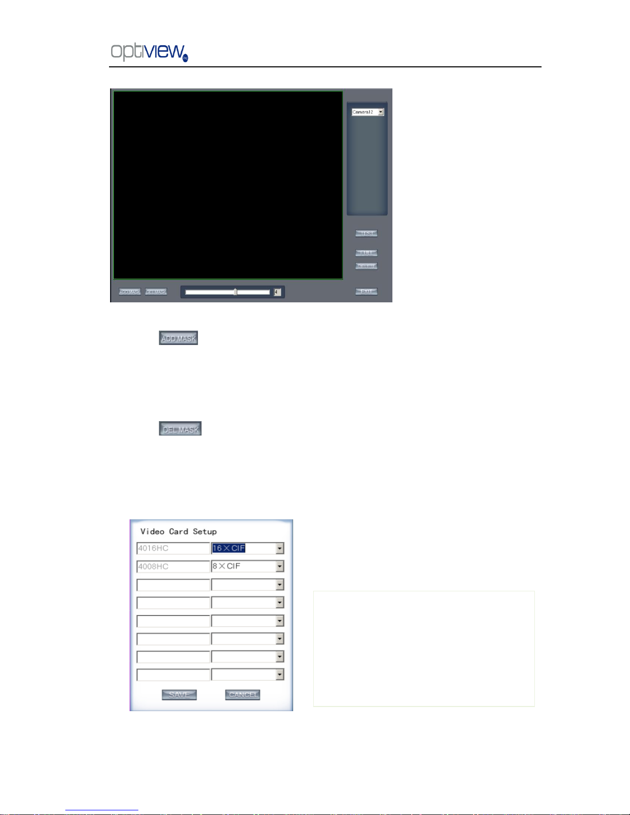
1. Add mask/Delete mask
Press button to set the area to be covered with a black mask. If there are some areas
that you don‘t want to show, you can draw those areas with the mouse until they change to black.
You can set several cover areas. Press this button again when finish adding. This must not be used
as masking for motion detection. This is often used on ATM machine or bank vault when you do not
want the punching of PIN numbers recorded on the video for security purposes.
Press button to delete all cover areas.
14. DVR board work mode setup
Each DVR system supports a maximum of 8 PCs 400XHC (total channel is equal to 64) series
board, so user can set its work mode via this GUI.
For 4004HC, 4008HC, 4016HC series
board model, you can set its work mode. The
new DVR board work mode will only take effect
after rebooting DVR Server software.
Page 17

DVR Server Manual ver.5.05/rel.092507
13
15. Keyboard shortcuts setup
1.2.5 Network panel
This panel displays the network configuration of DVR system.
Information of network
adapter
IP address of the system
Subnet Mask
Default Gateway
(NetGate)
When client is linked, its IP
address will display in this window (the
current IP only).Press the right mouse
button to disconnect the client.
You can select from this setup which of the
keyboard shortcuts you do want to enable or
disable. These shortcuts allow you to use function
keys on your keyboard to run a command such as
zooming on a camera, run an auto tracking
cameras etc…
Page 18

DVR Server Manual ver.5.05/rel.092507
14
1.2.6 PTZ Control panel
1.2.6.1 Relay (On/Off)
Control the PTZ cameras internal relay (relay1) or the decoder‘s relay (relay 1).
Used to turn on a light or control an access gate.
1.2.6.2 Wiper (On/Off)
If using the PTZ cameras corresponding wiper control relay, this toggles the
relay/wiper on and off.
1.2.6.3 Zoom + / Zoom –
Controls the zoom function of the PTZ camera.
1.2.6.4 Focus + / Focus –
Overrides the auto-focus setup of the PTZ camera, adjust focus the image.
1.2.6.5 Iris + / Iris –
Overrides the PTZ cameras auto-iris and brighten or darken the image.
Pressing this button initiates the connected PTZ camera to do an automatic
tour of 360, but for speed domes, many PTZ factory forbid this command. This
may not be available to some PTZ cameras
By pressing and holding these buttons, the PTZ camera will move up,
down, right and left as well as other directions.
In DVR system, there are three ways to operate the
PTZ;
a. Panel operate;
b. Operate in video area directly ;
c. Keyboard operate
Page 19
DVR Server Manual ver.5.05/rel.092507
15
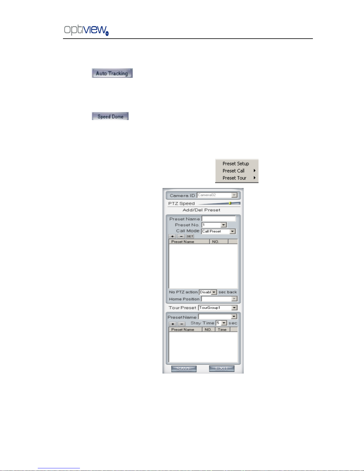
1.2.6.6 Auto tracking (On/Off)
Press button to use the PTZ camera tracking the floating object automatically.
1.2.6.7 Speed Dome
Press button to operate the speed dome, including Preset Setup, Preset Call
and Preset Tour:
1.2.6.7.4 Preset Setup
In this screen you can set the preset position:
PTZ speed setup
Press and drag the slider bar to adjust the speed of PTZ.
Page 20
DVR Server Manual ver.5.05/rel.092507
16
Add/Delete preset
In this section you can set the preset name with its sequence number, then you can press
/ button to add/delete a preset. When you want to modify the preset you can press button
to confirm your modification. For different cameras, they have different commands to open and set,
so you can choose the call mode in the drop-list for different cameras.
Home position
You can set a home position for the PTZ. When there are no PTZ actions after the setting time,
the system will return the PTZ to the home position.
Tour preset
In this section you can set the tour schedule. First you can choose a group, and then set the
track for this schedule; you can press / button to add/delete a preset to it. After you choose
the preset name you can set the time to keep on.
1.2.6.7.5 Preset call
When you select this function, system will show all the preset names you set in Preset Setup
menu; you can click one to move to it.
1.2.6.7.6 Preset Tour
When you select this function, system will show the entire tour groups you set in Preset Setup
menu; you can click one to execute it.
1.2.6.8 Control PTZ via video window
You can press the mouse and drag it to a direction to move the PTZ camera.
Page 21
DVR Server Manual ver.5.05/rel.092507
17
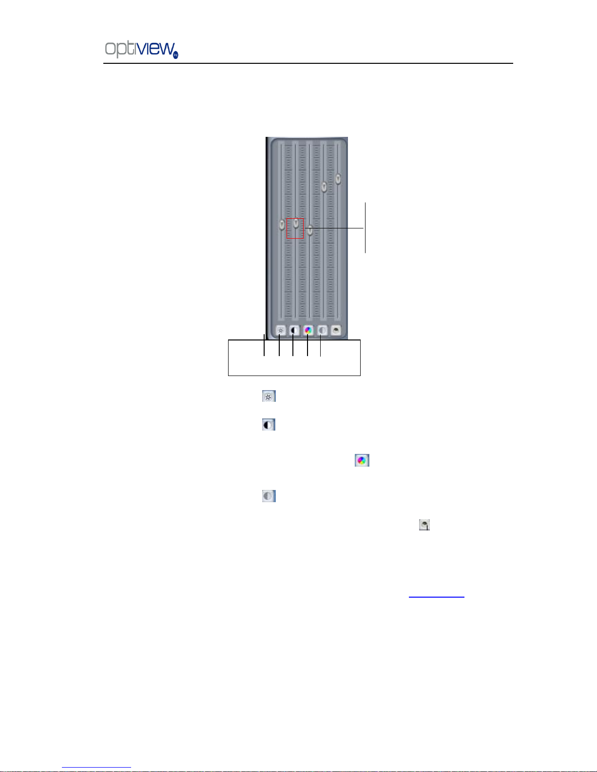
1.2.7 Color and Audio adjustment
① Press the first button and drag to adjust the brightness of the image that you selected. You
can reset its default value by pressing .
②Press the second button and drag it to adjust the contrast of the image that you selected. You
can reset its default value by pressing .
③Press the third button and drag it to adjust the hue of the image that
you selected. You can reset its default value by pressing .
④Press the fourth button and drag it to adjust the saturation of the image that you selected. You
can reset its default value by pressing .
⑤Press the fifth button to switch sound of the audio that related to the image you selected and
drag the bar to adjust the volume. You can reset its default value by pressing .
1.2.8 Matrix & display
This panel includes matrix group and display group. Each group includes 16 numeric buttons;
each button denotes one type of matrix or display. This will be described in System setup.
↑Increase
↓Decrease
① ② ③ ④ ⑤
Page 22

DVR Server Manual ver.5.05/rel.092507
18
1.2.9 DI/DO Control
1.2.9.1 DI control
Press number button to forced a sensor to activate or deactivate and overide the current
settings in sensor setup. The channel of DI and DO is determined by the setup of DI/DO device you
set in System setup. The status of DI has three types:
Input channel 1 is deactivated.
Input channel 1 is activated.
Input channel 2 has an alarm.
When there is no alarm, user can press number button to enable sensor forcibly. Press the
button again to stop the DVR in checking the sensors all the time, then the DVR system checks
sensor according to configurations set at the Sensor setup. When there is an alarm, the
corresponding button will show the alarm with green color.
1.2.9.2 DO control
Press number to open/close alarm device relay switch manually. The status of DO are show
below:
Output channel 1 is close.
Output channel 2 is open.
When no alarms are triggered out, user can press the number button to output alarm forcibly
and the button will show it with green, press it again and the output will be closed.
Page 23

DVR Server Manual ver.5.05/rel.092507
19
Chapter 2 Local setup
The DVR System Configuration Menu include 7 groups of configuration setup:
System setup Camera setup
Sensor setup PTZ & linkage setup
Email setup Matrix & display setup
User setup
Refer to the Tutorial video for other selected details about this topic. The tutorials are small video file that can be played from
the local DVR system. It will illustrate many of the common task involved in working with your DVR system.
Please follow the link from the desktop ―Click here for Technical Support and Serial number‖.
Page 24
DVR Server Manual ver.5.05/rel.092507
20
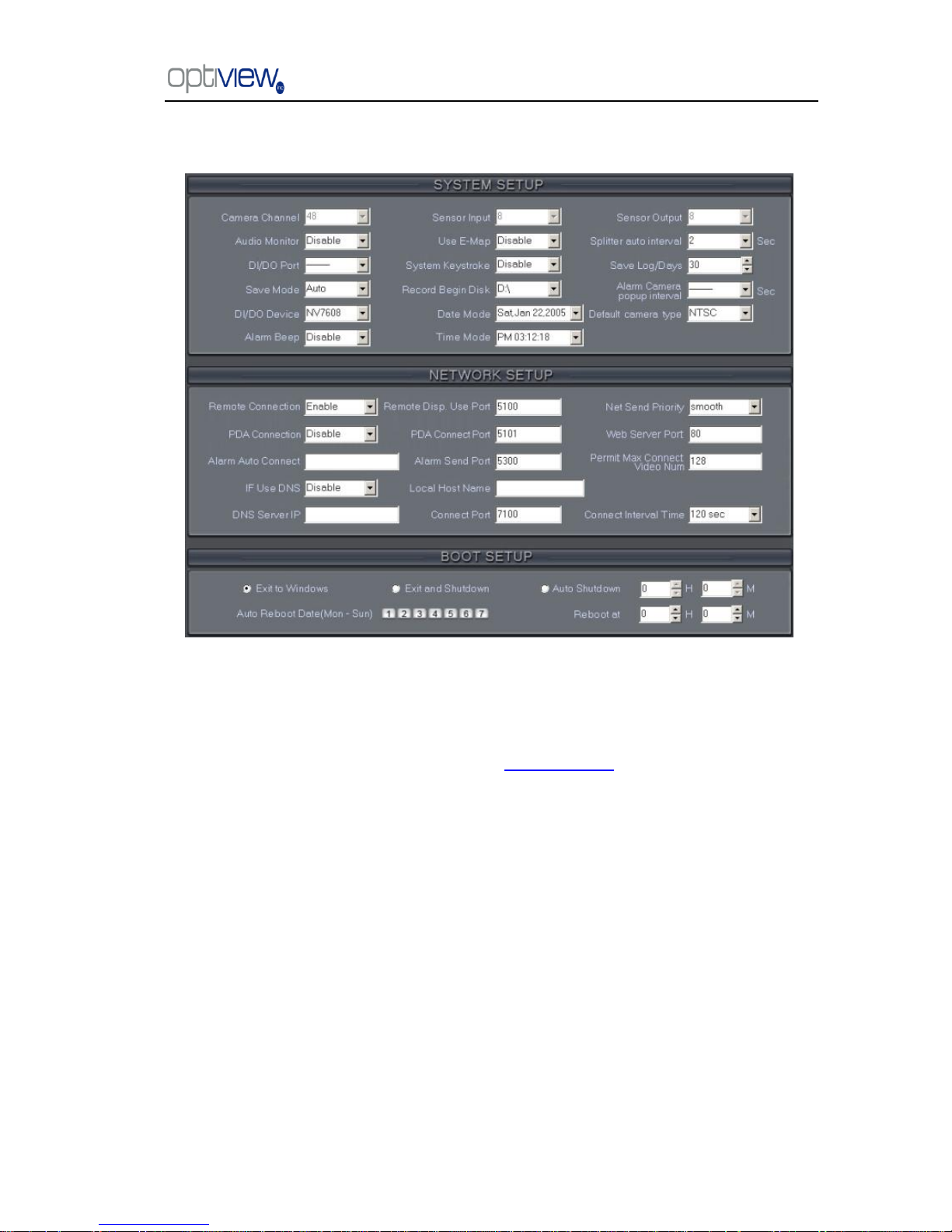
2.1 System setup
2.1.1 System setup
【Camera Channel】Displays the number of total channel on the DVR system. This information
is non-changeable and it is based on the DVR card installed on the system.
For IP Camera, you should set it separately at IP Camera setup.
【Sensor Input】 Display number of sensors (DI).
【Sensor output】Display the number of alarms(DO).
【Audio Monitor】Select real-time monitoring audio.
【Use E-Map】Select use Electronic Map or not.
【splitter auto interval】Set auto-split changing interval time.
【DI/DO Port】Select sensor/alarm driver connecting port, it must be different from PTZ Port. If
you do not use alarm input, you can close this function. To avoid conflicts to the PTZ port, you should
set and use the different ports for these two functions.
【System Keystroke】System keystroke. When it is enabled, functions of some Window
system keys will be disabled, e.g. minimize (Ctrl+Alt+Del included).
【Save Log for/Days】Log save days(max 100 days).
【Save Mode】The way the DVR will handle recording on the hard drive can be set on this setting.
“Overwrite” will auto-delete the oldest recorded data when there is not enough or no more hard drive
space available during recording. “Stop Recording” will cause the DVR to stop recording when the hard
drive is full and it will give a warning message. (Notice: each disk will reserve 1000M space).
Page 25

DVR Server Manual ver.5.05/rel.092507
21
【Record Begin Disk】Select the first disk from which the DVR system saves data. The
prior disks before the selected drive will not be used to store video files and it will not be checked by
the system. When the capacity of HDD is not enough or there are some mistakes while recording,
system will inform the failure of recording and the corresponding camera will stop recording.
【Alarm camera popup interval】Set the interval of alarm camera, if you select‖—―,you
can‘t select function ‖Start alarm popup‖.
【DI/DO Device】Select receive alarm device type. When you change the type of alarm
device, you should reboot the system to update the device information in DI/DO control panel.
Note: Currently, system support following NV serials DI/DO devices: NV7608, NV7609, NV7616, NV7616B,
NV7632 and NV7632B. NV7632 includes two NV7616 (or combination of NV 7608 and NV 7616), and
NV7632B includes two NV7616B. When you select these two selections you must set their decoder address as
1 and 2, and they should connect with PC through RS 485 converter after they connect parallel with each other.
【Date Mode】Select the way to display the date. It assigns the date display mode of the
DVR system, including the information panel on the main screen, the date panel of the playback
window and OSD date in video.
【Alarm Beep】Select disable or enable from drop-down list. If you select ―enable‖, when
there is an alarm, system will make beep sound.
【Time Mode】Select time format from the drop-list. After you change the format it will
affect the OSD format, information in information display panel and file lists.
【Default Camera type】Set the default mode of video from PAL and NTSC. It is available
when the input video is lost and for the decoder to playback local video to TV Wall.
2.1.2 Network setup
【Remote Connection】Select to allow remote connection or not. If you select ―disable‖, it will
not permit any client to connect this DVR system.
【Remote Disp Use Port】Select remote connection port for Clients.
【Net Send Priority】There are three items selected."smooth‖ sets the system to have a large
buffer."realtime"sets the system to have enough bandwidth. Otherwise, the data off and on when
it is sent from the network.
【PDA Connection】Select whether allow PDA connect to DVR system. If you select ―disable‖,
it will not permit any PDA device connect this DVR system. Note:
To use PDA connection normally, the board card should support dual compression and user must set dual
setting in local setup (can’t set remote image same as recording).
【PDA Connect Port】Select remote connection port for PDA device.
【Alarm Auto Connect】Assign a network client to receive alarm message when there is an
alarm. The alarm channel image will auto display in the client software. But user must be sure that
client is running on that IP address.
Note:
Alarm auto connection to IP is used to input alarm automatically. When sensor, normal or motion record
is set to input and there is an IP address, the system will check if the client has connected with this
system. If there is no connection, the system will try to connect with it through Port 5300(preset). While
it cannot be connected, the system will keep trying till the connection is OK.
Page 26

DVR Server Manual ver.5.05/rel.092507
22
So please ensure that your client’s program is in use, Port 5300 is listening and the network is in good
condition. If not so, the system will not be stable.
【Alarm Send Port】This is the alarm message connecting port, which is used to send alarm
from DVR Server to Client.
【Web Server Port】The IE client connecting port. Default value is 80 for http access; but for
some windows XP editions, it shields 80 port. In this case, user should modify this port to other port,
such as 1280. The user must reboot DVR server to activate the port changes, then user can access
DVR server via IE Client as follows: http://IP: 1280 (IP can be a static IP or dynamic domain name).
【If Use DNS】 Select use DNS or not, support dynamic IP.
【Local Host Name】Input the name description for DNS Server identification.
【DNS Server IP】DNS server host IP.
【DNS Connection Port】DNS server host port, it is used to connect DNS server.
DNS server work mode:
1. If your DVR is dynamic IP, you should set your DVR system as follows:
2. DNS server will get domain name and current IP of your DVR, NVR Client can connect DVR
server through this domain name.
Page 27

DVR Server Manual ver.5.05/rel.092507
23
3. NVR Clients get IP of DVR through DNS server according to its domain.
4. NVR Clients visit DVR through the IP that it obtains from the DNS server.
【Interval Connection Time】Set the interval time to connect DNS automatically.
【Permit Max Connect Video Num】The maximum number of client connections that the DVR
will allow. The number of connections will depend on the network bandwidth. The maximum remote
client connections are 256. For example: one DVR server is using a 2Mbit network bandwidth if all
video channels are compressed based on CIF resolution (max data bit rate is 500Kb).It is
recommended to set it to allow four client connections
2.1.3 Boot setup
【Exit to Windows】 User can exit DVR program and go to windows desktop.
【Exit and Shutdown】User can exit DVR program and shut down computer.
【Auto Shut Down】Set the time to shut down the computer .
【Auto Reboot Date(Mon-Sun)】Pre-set the date and time for the PC to reboot.
【Reboot at】Set auto-reboot time.
Page 28

DVR Server Manual ver.5.05/rel.092507
24
2.2 Camera setup
2.2.1 Camera setup
【Selected Camera】Select from the drop-down list a camera number you would like to
configure. Any setting changes on the selected camera will only affect the camera number selected,
unless explicitly specified at the option called ‗Copy to Setup to: All cameras‖ (which will be
discussed later on this chapter). IP Cameras are not included. For IP Camera, you should set it
separately in IP Camera setup.
【Camera Description】You can label your camera at your own choice of name, such as warehouse
door 1, main lobby etc.
【Camera Type】Select camera type from drop-down list. Users can choose from PAL and
NTSC.
【Camera】Enable or disable selected camera.
【Remote Frame Rate(fps)】Set the frame rate of the client.
【Bit Rate】Set recording mode. Variable Bit Rate (VBR) or Constant Bit Rate (CBR) Recording.
VBR allows each frame to be recorded at a dynamic bit rate depending on the image
complexity, activity and color.
CBR allows each frame to be recorded at fixed bit rate, regardless the scene activity. In
many cases, this limits detail (resolution). The benefit of CBR is its ability to accurately estimate the
total video capacity.
【Frame Rate(fps)】Set the recording rate for selected camera. For Frames per Second (fps),
Page 29

DVR Server Manual ver.5.05/rel.092507
25
the frame rate should be from 1 to 30 fps. While image size is set ―704*576‖, the frame rate should
be set around 1 to 15 frame.(only for HC Series)
【Remote Image size】Select image resolution to be transmitted to clients. When you set the
【Image Size】as 4CIF(704*576), this configuration is not available, the program will select it as CIF
automatically because the DVR board does not support dual stream when it records with 4CIF
resolution. (only for HC Series)
【Image Quality】Sets the quality of the image to be recorded. Select from Poorest, Poor,
Medium, Very good and Best.
Click this button to make advanced setup for video quality, you can set I P B frame and
maximum bit rate.
(Note: If you don‘t familiar with those features, we advise you NOT to revise them)
Recommend setup:
For CIF:
Image
I frame
P frame
B frame
Max bps
Best
12
12
17
900000
Good
15
15
20
750000
Medium
18
18
23
600000
Low
21
21
26
450000
Lowest
24
24
29
300000
For DCIF:
Max bps = (Maxbps/3)*5 Note: Maxbps is the CIF‘s value with the same configuration(IPB)
For D1:
Maxbps = (Maxbps/3)*8 Note: Maxbps is the CIF‘s value with the same configuration(IPB)
【Alarm Adjust fps】Select enable or disable, If you select ‖enable‖, and an alarm occurs, the
camera will record with real-time frame rate (25fps or 30fps) ,even though 【Frame Rate(fps)】 has
been set other values(eg:5fps).
【Remote Quality】Set the image quality of the clients to be recorded from Poorest, Poor,
Medium, Very good and Best.
Click this button to enable users to make advanced setup for video quality of client end,
also can setup I P B frame and adjust maximum bit rate according to the network bandwidth.
.
Page 30

DVR Server Manual ver.5.05/rel.092507
26
【Image Size】Set the resolution for local record. There is an item ―704*576‖, each channel can
be set ―704*576‖, but not real time, system will select frame rate automatically around to
12-15fps(only for HC Series)。To get the best effect, you should set the resolution of local record
according to your CPU configuration. See the referenced configuration sample as below:
Computer configuration:
CPU: Intel Pentium 4 or Higher
Motherboard: ECS 848P-A or better
Graphic Card: ATI 9550 128MB,
Memory: 512MB
HDD: 120G (IDE)
Recommended resolution configuration for different channels:
DVR Board Channels
Recommended Resolution
Remark
64
CIF
Continuous recording is not
recommended
48
CIF
40
DCIF
CIF
32
DCIF
CIF
24
DCIF
CIF
Less or Equal to16
4CIF
DCIF
CIF
【OSD Date】Select whether to display the OSD date on the screen or not. When you select
―Not‖, the date will not display on the screen of corresponding channel.
【Masking Bitmap File】Watermark function, the logo picture must be edited ad 128*128 pixels
file size and saved as .bmp format.
【Record Days】This section allows users to determine how long the record data of each
camera should be kept by the system. The maximum duration for on-line storage is 120 days. Users
can select the exact number of days, or select ―auto‖ mode. If you select ―auto‖, the system will
auto-delete the recorded data of the earliest days when there is not enough space.
*NOTE: If there is not enough space of HDD, the system will delete the recorded data according to
the length of saving time of each camera. Eg: there are four cameras, the 1st camera saves 2 days,
the 2nd camera saves 5 days, the 3rd camera saves 10 days, and the 4th camera we will set to―auto‖
mode. If there is enough space, the 4th camera‘s record data will save in HDD, when there is not
enough space, the system will delete data automatically. If the 4th camera‘s record data has been
saved more than 10days, the system will delete the 4th camera‘s data. If the 4th camera‘s record data
has been saved less than 10 days, but the 3rd camera‘s data is more than 10 days, the system will
delete the 3rd camera‘s data. So, even if you set the 3rd camera‘s record data saving to10 days, the
data that is saved can be less than 10 days. The system will delete the record data from the earliest
date.
Page 31

DVR Server Manual ver.5.05/rel.092507
27
【OSD Contrast】Set OSD displaying brightness & position. An ―auto‖ item in the OSD
Contrast‘s drop-down list will make OSD suit the background‘s color automatically.
【Copy Setup to】Set other cameras with the same setup.
Notes:
1. If less than 64 cameras are used,disable all unused or inactive camera channels.
2. The unit of the swap file should be MB. The range is 2 to 50.
3. Set the position and contrast of the date shown on the screen. Sometimes the date cannot be
clearly seen for its color is similar with the background. You can change its position or color when
this happens.
4. Image size is the format used when recording. Remote image size is the format used when these
images are transmitted to client sides.
5. Remote Frame Rate, Remote Image Size and Remote Quality are the parameters of the client
side. When the server‘s image size is set as ―704*576(12fps)‖, these three items are not in effect,
and client‘s parameters will be same as server. When the server‘s resolution is set as others (except
―704*576(12fps)‖), if Remote image size is set as ―Same as Rec‖, Remote Frame Rate (fps) and
Remote Quality are not in effect and the client‘s parameters will be the same as the server.
6. Variable digital rate table
Image quality
record environment
occupied disk space (/cam/hour)
Poorest
low action, indoor
about 50Mb
high action, road
about 100Mb
medium
low action, indoor
about 75Mb
high action, road
about 190Mb
best
low action, indoor
about 175Mb
high action, road
about 350Mb
Variable digital rate recording is recommended.
2.2.2 Group setup
Note: If you set a camera into several groups, only the last setup is available.
【Selected Group】Select group number.
【Swap File(M)】Sets the increment of the video files size when it is saved on the hard drive..
For easy backup, don‘t set a large file size. Up to 512M can be set, but 30M is recommended.
【Selected Cameras】 Select the camera that has the same work mode with group. Cameras
include local board card and IP module
【Pre-Event Record】 Select the start time to record prior to an alarm. When the DVR system
is in the Motion Detect mode or the Sensor Detect mode, it can record video before the alarm is
trigged.
【Post Record Time】Select the end time to record after there an alarm. When the system is in
Motion Detect mode or Sensor Detect mode, it can record video after the alarm ends.
【Record Mode】Selects whether program records audio data or not, this setting is not
available for IP Cameras, for stream type of IP Camera, you should set it remotely in IP Camera
setup.
Page 32

DVR Server Manual ver.5.05/rel.092507
28
Recording Schedule Setup (setting for cameras of local board cards and IP Modules.)
Tips: One block of pane means half an hour. First, click record mode icon , then click
schedule diagram, hold down the mouse and move it to select the corresponding area to
record. (Drag & Drop).
1. Normal Record (Green): DVR System is always recording video. (e.g. Sun. Fri. Sat.)
2. Motion Detect (Blue): DVR System begins to record video only when it detects moving objects.
(e.g. Mon.)Click "Motion Detect" icon, then select your schedule time by drag & drop. For example,
the above picture means: on Monday it is set to motion detect record, on Sunday it is set to normal
record, but on TUE, WED and THU from 3:30 to 11:00 it is set to sensor record, from 14:00 to
22:30 it changes to both motion detect record mode and sensor detect record mode, the remaining
time is set normal record.
3. Sensor Record (Red): DVR System begins to record video only when there is a sensor alarm.
(3:30 to 11:00 in Tue. Wed. Thu.)
Note: The time setup must be correspond with Check Alarm setups in Sensor setup otherwise it will
not work properly.
4. Motion or Sensor Record (yellow): Combine with above 2 and 3 function.
5. Not Record (gray): DVR System does not record video.
Page 33

DVR Server Manual ver.5.05/rel.092507
29
2.3 Sensor setup
2.3.1 Sensor setup
【Select Sensor】Select the sensor from the drop-down list in order to set the parameters for it.
【Sensor】 Select this sensor port to use or not.
【Sensor Position】Enter the description of your sensor location for easy identification.
【Speed Dome Preset】 Select linkage of Speed Dome preset number . Speed Dome will
move to this preset number automatically when there is an alarm. (Speed Dome installation
needed).
【Alarm Play sound】 Select a sound of (.wav file) for a sensor, if there is an alarm, the sound
file will play.
【Tied to Cameras】Select camera that is related to this sensor alarm.
2.3.2 Group setup
Sensor group setup is very similar to the group setup of camera recording.
【Selected Group】Select group number.
【Sensor Type】Select NC or NO alarm type.
【Alarm Write log】Select write alarm log or not.
Page 34

DVR Server Manual ver.5.05/rel.092507
30
【Alarm Action】Select system alarm linkage mode when an alarm stops. ―Stop Immediately‖
means the system will stop the alarm immediately after the alarm driver stops an alarm.
―Do Not Stop‖ means the system will not stop the alarm after the alarm driver stops an alarm.
―Wait‖ means the system will stop the alarm at your setting time after the alarm driver stops an
alarm.
【Sensor input】Add sensor to selected group.
【Tie to cameras】Set cameras to be related to this sensor group. They will start recording and
connect remote network client automatically when there is an alarm. The cameras just include the
cameras of local board card; IP Cameras are not included. For IP Camera, you should set it remotely
in IP Camera setup.
【Tie to Relay Output】Add alarm devices (alarm out port) to this group such as siren, light. All
connecting devices will send alarm message when there is an alarm.
Schedule Setup (Example for below figure)
1. Check Alarm (Red): DVR System responds with sensor during this time. (00:30 to 12:00 from Sun.
to Sat.)
2. Do Not Check (gray): DVR System doesn‘t respond with sensor in this time.
Note: If you set a camera in several groups, only the last setup is available. This means if one
camera is used and configured on more than one group, the last settings configured using that
camera will be used and the previous settings will be overwritten by the latest settings.
Page 35

DVR Server Manual ver.5.05/rel.092507
31
2.4 PTZ & Linkage setup
2.4.1 PTZ protocol setup
【Selected Camera】Select the camera from the drop-down list to set the parameters. The
cameras just include the cameras of local board card; IP Cameras are not included. For IP Camera,
you should set it remotely in IP Camera setup.
【PTZ Port】Select PTZ connecting port, when you do not use PTZ port, please choose ―------‖.
【PTZ Protocol】Selects the PTZ protocol for the PTZ camera.
【PTZ Address】Set the camera ID number of the PTZ camera being controlled.
Note: The PTZ camera has a dip switch to set the PTZ address. The PTZ camera ID number must
match the number of this dip switch. The actual Dip switch settings from the PTZ camera must
match the settings on this PTZ menu, otherwise the PTZ will not be able to communicate properly
thereby it would fail to pan, tilt or zoom. PTZ configuration changes on this menu will not change the
actual PTZ dip switch settings on the PTZ camera.
【PTZ Baud rate】Select PTZ Baud rate for the PTZ camera.
【PTZ Position】 Select the installation mode of the PTZ according to its installation mode.
Notes:
1. PTZ position will influence PTZ control. E.g.: if you set it as obverse and press left, then it will turn
left. If you set it as inverse and press left, then it will turn right.
2. If there is (H) after the PTZ protocol, it has the high speed of Preset function. If there is no (H), it
only has ordinary functions.
3. The PTZ address will be sent as a message option. Take care that some address begins from 0.
That is to say,when the address number is 1, the real address is 0. So we must set it according to
their relations.
Page 36

DVR Server Manual ver.5.05/rel.092507
32
2.4.2 Motion detection relay & remote client alert
【DO Port】 & 【DO Description】Select a DO port and set its name to identify the various DO
port. It will be shown as a tip when the mouse moves closely or above the DO button in DVR Server
or NVR Client.
【Select Camera】Selects camera to be set from drop-down list.
【Alarm Send To Network】Select sending alarm to network clients or not.
【Motion Alarm Play Sound 】 Press button to selects a ―.wav‖ sound File for a motion
alarm. If there is a motion alarm, the sound file will be played. Also, you can test it by pressing
button.
【Video Loss Alarm Play Sound 】 Press button to select a ―.wav‖ sound File for a video
loss alarm. If there is a video loss alarm, the sound file will be played. Also, you can test it by
pressing button.
【Camera Alarm DO Output】Selects which DO ports will be triggered by above camera
alarms.
Schedule Setup (setting for cameras of local board cards, IP Cameras are not included.)
1. Motion & Video Loss (Red): DVR System responds with Motion Detection and Video Loss
alarm in a specified time.
2. Motion Alarm (Blue): DVR System only responds with Motion Detection alarm in a specified
time.
3. Video Loss (Yellow): DVR System only responds with Video Loss alarm in a specified time.
4. Not Check (gray): DVR System doesn‘t respond with any alarms in specified time.
Note:
Check Alarm Setup (including Motion & Video Loss, Motion Alarm and Video Loss) does not affect
the Motion Detect Record. It only applies to Motion Detect Alarm out and Motion Detect Alarm to the
network.
Page 37

DVR Server Manual ver.5.05/rel.092507
33
2.5 E-mail setup
Note: Before you configure the E-mail setup, you should pay attention to several points as
mentioned below:
The alarm to trigger E-mail sending includes two types: Camera-related alarms (Motion
detection alarm & Video loss alarm) and Sensor-related alarms.
For Camera-related alarms, you should set Motion detection area & Cover setup and to check
alarm in Motion detection relay & remote client alert. For Sensor-related alarms, you should set to
check sensor and select cameras to be triggered in Sensor setup.
When you enable system capture image as attachment of E-mail, the system will capture a still
picture of camera for Camera-related alarms or related camera for Sensor-related alarms to be sent
as an attachment with E-mail.
2.5.1 SMTP setup
【SMPT Server】SMTP server address, eg: mail.mycompany.com,
【SMPT Port】SMTP listen TCP‘s port for connect request.
【Auth.Type】Logon mailbox, operator will select SMTP authentic type. Or select ―simple login‖.
【Login User ID】Mailbox‘s ID.
【Login Pass】 Mailbox‘s password.
After you have finished the user setup, press to test the function.
Page 38

DVR Server Manual ver.5.05/rel.092507
34
2.5.2 E-Mail setup
【Send To】Set E-mail address of recipient (where E-mail is to be sent).
【Copy To】Set additional Email address of recipient to whom system sends E-mail.
【User Email】 Enter email address of sender.
【Email Title】Enter title of the E-Mail to be sent.
【Grab Picture As Attachment】When there is an alarm, the system will grab picture, operator
can select whether to send the picture as an attachment of the E-mail.
【Alarm Send Email Cameras(Screenshot From Alarm Camera)】Operator can select the
cameras, which will trigger to send E-mail when they have alarms. The cameras you can select are
only the cameras of the local board card, IP Cameras are not included.
【Alarm Send Email Sensors(Screenshot From Linked Camera)】Operator can select the
sensor, which will trigger to send an E-mail when they have alarms.
*NOTE: If you select to send the grab picture as the attachment, you should check the alarm of the
camera or the sensor, and set ―alarm send to network‖ to be enabled.
2.6 Digital matrix setup
2.6.1 Matrix setup
【Matrix Group】System operator can set groups of video images to be sent out through the
matrix decode card. Each group has a different display mode. You can set up to 16 groups.
【Video Out Port】Select the output port of the Matrix card that you want to set, the total
number of channels is decided by Matrix Decoder card.
【Video Out Standard】Set Matrix video out to standard, you can select from PAL and NTSC.
Page 39

DVR Server Manual ver.5.05/rel.092507
35
【Video Split Mode】Select video output display mode, there are 1split , 2split ,
4split , 9split , 13split and 16 split .
【Video Window】 & 【Display Camera in the window】After selecting video split mode, there
will be a corresponding display video window. Select one camera or several cameras to show in the
window. The Video cameras allowed to be used can be any cameras from the local board card and
IP Cameras. For cameras from the local board card, the system uses soft decoding to play to TV
Wall. The total number of channels is not influenced by decoding channel. For IP cameras, the
system uses hard decoding; the total number of channels is influenced by decoding channels. For
different work mode (set in IP Camera list. If you disable hard decoding by setting in IP Camera list,
you can‘t output real-time video of IP camera to TV Wall.
*Note: one camera is only showed in one window once.
【Switch Video Interval(sec)】When there is more than one camera selected you can set the
interval to display the cameras in a circular fashion.
2.6.2 Display setup
【Display Group】 System operator can set groups of cameras to display for fast preview,
including its display mode and cameras. Up to 16 groups can be set.
【Video Split Mode】Set the split mode, the split mode is same as main window‘s display split
mode. There are1, 4,9,13,16,20,25,28,33,36,40,49 and 64 partition modes.
【Video Window】 & 【Display Camera in the window】After selecting video split mode, there
will be corresponding windows, select one camera show per window. The cameras include 64
cameras, when the total channels (cameras of local board card and IP Cameras) are less than 64,
some channels do not have image with black window.
*Note: One camera is only showed in one window once, but each camera can display any window
discretionarily. E.g.: The 1st camera has been displayed in window1, and the 2nd camera has been
displayed in window2. When the 1st camera was reconfigured to be displayed in window2, the 2nd
camera will be exchanged in window 1 automatically.
Page 40

DVR Server Manual ver.5.05/rel.092507
36
2.7 User setup
2.7.1 User information
【Local Password】 Check to enable User Manage mode for local PC DVR, and activate the
lock button in main window. Only authorized users can log into Optiview System at User
Manage Mode.
【Auto lock time】Select a time to enable system to lock automatically when there are no
activity such as a user doing a playback or changing configurations of the software.
【Network Password】 Check to enable User Manage mode for Client. When you enable this
function, client must pass the authentication to connect with PC DVR.
【User Name】Input new User ID in this box when adding a new user to system.
【Auth. Level】Select user type. Only an Administrator can enter the User Manage Window and
have the power for editing the user management menu.
【Password】Set new user or selected user ‘s password.
【Password Confirm】 Confirm password again.
【Note】Input your description of this user.
【New User】Press button to edit the user you want to add in the 【User Name】
blank. Input User Name, Note Name, Password, and Confirm Password. Select Manage Right
(Administrator or Operator), and then click Add User to save.
Page 41

DVR Server Manual ver.5.05/rel.092507
37
【Add User】Up to15 users can be added to system except Admin. Click icon to
add new user you edited to user list.
【Modify User】 Select a user from user list, then click button to modify it.
【Delete User】 Select a user from user list, then click button to delete it.
2.7.2 User right setup
【Select setup items】Select an item from the drop-list and then choose the cameras for the
users. These items include【Camera View Right】, 【Camera Playback Right】,【Camera Audio Right】,
【PTZ Control Right】.
【Camera View Right】Select cameras that can be viewed by the user you are setting up. The
cameras you can select include the cameras from the local board card and IP Cameras. By default,
every user is granted access to all live images. To deny access, you can click the desired cameras
button and the color will change from blue to gray (by default, user ―admin‖ is super user, you can‘t
modify its rights, it has fixed access rights).
【Camera Playback Right】Select the cameras to have playback rights by the user you are
setting. The cameras you can select include the cameras of the local board card and IP Cameras.
By default, every user is granted to playback video data of all cameras. To deny access, you can
click the desired camera button and the color will change from blue to gray.
【Camera Audio Right】 Select cameras whose audio can be heard by the user you are
setting. The cameras you can select include the cameras of the local board card and IP Cameras.
By default, every user is granted to check audio of all cameras. To deny access, you can click the
desired camera button and the color will change from blue to gray.
【PTZ Control Right】 Select the cameras that the selected PTZ can be controlled by the user
you are setting. The cameras you can select include the cameras of the local board card and IP
Cameras.
【Operation Right】Select operational tasks, granting or denying rights. Operational tasks are
normally reserved for administrative, privileged accounts. Operators are rarely granted rights to
adjust camera color, exit program, explore files etc.
【Setup Right】
Select setup rights to grant or deny user privileges.
Page 42

DVR Server Manual ver.5.05/rel.092507
38
Chapter 3 IP Camera Setup
Note: for IP camera setup, its alarm and related setup will only be available when you set it
remotely; the Local setup of PC DVR is not available for IP Cameras except Recording Schedule in
Camera Setup
Functional buttons
There are 5 buttons in each page located at the bottom. They are Upgrade, Restart, Time
adjustment, Save and Exit.
The system can upgrade to the server remote. Click this button, and select the
right file.
Some settings will only come into effect after the device reboots.
Adjust date and time of DVR or EMDVR. The new date and time will be copied
from NVR client computer.
After setup is finished, click this button to save the setup.
Exit setup.
Remote setup for DVS including Server, Channel, PTZ, Sensor and Alarm.
Page 43

DVR Server Manual ver.5.05/rel.092507
39
3.1 Server setup
Press button to set server parameters remotely:
In the server window, some blanks‘ background are gray. Those parameters are read from
foreside server, you can‘t modify them. Other blanks whose background is white, can be set
remotely.
【Server Name】Enter the name description for easy identification. This name delegates the
foreside server. If use DNS to get IP, this name will be used.
【IP configuration and related】
【Server IP】
【Port】
【Subnet Mask】
【Net Gate】
【Net Cable Type】
【Connection configuration and related parameter】
【Use PPPOE】
【PPPOE Login Name】
【PPPOE Login Pass】
【User Pass】Set the user password of DVS remotely, after that operation you should change
the Login Pass to corresponding value in Add / Modify server. Otherwise, you can‘t connect the DVS
correctly.
These are network configurations; you can set LAN or
Internet IP according to your own LAN settings.
If system uses PPPOE to connect with web, please
select it and input the PPPOE login ID and password.
Page 44

DVR Server Manual ver.5.05/rel.092507
40
【DNS Server IP】If use DNS, input the DNS host IP address.
【Remote manage】
【Remote manage IP】
【Remote manage port】
3.2 Channel setup
Press button to set channel parameters.
This section contains the parameters to designate a name for every camera connected, to
enable or disable show LOGO and OSD, and to set display type of OSD & LOGO as well as record
resolution, record type, record quality and frame rate, etc.
【Camera】Select the camera to be set from the drop- list.
【Camera Name】Enter a name description for easy identification.
【Show LOGO/ OSD/ Week】If you check this box, the system will show corresponding
information on screen.
【Position】Set the position of OSD or Logo by entering the X and Y coordinates directly.
【OSD】Set the display attribute of the OSD & LOGO. There are four types of display modes:
Clarity-Glitter, Clarity-Not Glitter, Not Clarity-Glitter and Not Clarity-Not Glitter.
【OSD Type】Select the type of OSD for the Week.
【Privacy Mask】You can check this box to set the privacy mask on the below image directly,
and you can clear some privacy masks by pressing button.
【Video Setup】:
Set the IP address and port of host server who
will receive the message upload from foreside
server
Page 45

DVR Server Manual ver.5.05/rel.092507
41
【Frame Rate】Select the record rate of camera from drop-list.
【Resolution】Set the resolution at which the video files will be recorded. Choices are DCIF,
CIF, QCIF, 2CIF and 4CIF. The higher the resolution, the more disk space will be used.
【Stream Type】Select video and audio or only video record.
【Image】Set the quality of the image to be recorded. Select from worst, worse, normal,
good and best.
【Bit Rate Type】Select bit rate type from Variable Bit Rate (VBR) and Fixed Bit Rate (FBR)
record:
VBR range= Poorest, Poor, Medium, Good, Best.
FBR range = 45 Megabytes/Hour to 400 Megabytes/Hour.
【Max Bit Rate】Select the maximum bit rate for Variable Bit Rate (VBR) record.
3.3 PTZ control
Press button to set PTZ
In this screen, you can define the PTZ protocol and set the Preset Position as well as the plan to
execute them automatically.
【Camera】Select the camera to be set from the drop- list.
【Baud rate】Set baud rate according to PTZ protocol from the drop- list.
【PTZ Protocol】Select the communication protocol for the PTZ camera from drop-list.
Page 46

DVR Server Manual ver.5.05/rel.092507
42
【PTZ Address】Set the address of the PTZ camera, which must be matched with the value of
dip switch in the PTZ.
【Preset position & schedule setup】Define preset position and set time to call preset position
automatically. System can add and delete plan time.
【Copy to】After finishing one channel, if you want to set any other channels‘ configuration the
same as this camera, you can select the channel number from drop-list, and press button.
3.4 Sensor setup
Press button to set sensor parameters.
Page 47

DVR Server Manual ver.5.05/rel.092507
43
【Sensor NO】Select one sensor to be set.
【Sensor Name】Enter the name description of the sensor.
【Type】Select alarm type (sensor type) from ―NO‖(Normally Open) or ―NC‖(Normally Close).
【Policy】Selecting ―Sensor Alarm Handling‖ firstly, handling policies will be available as
follows:
Audible warning—Indicates the alarm with voice.
Upload to DVR Server—Update the alarm information to DVR system.
Trigger alarm out—Trigger alarm box to output the alarm.
【Trigger record camera】Set cameras to record when triggered by an alarm. You can select
one or more channels. When there is an alarm input, the cameras will be triggered to record (the
record type of the channel is Alarm Record), and the monitor will switch to preview the cameras
(warning on monitor is enabled).
【Preset】Set camera that will move to its one preset position when the alarm occurs.
【Schedule】Set alarm input precaution time first, then set the time segment according to the
sequence. The time of each segment should not overlap the others and no skips are allowed. After
the precaution time of a certain day is set, you can copy the parameter to other dates by selecting a
day and pressing the copy button.
【Copy to】After finishing one channel, if you want to set any other channels‘ configuration as
the same as this camera, you can select the channel number from drop-list, and press
button.
Page 48

DVR Server Manual ver.5.05/rel.092507
44
3.5 Alarm setup
Press button to set alarm parameters.
【Camera】Select a camera to be set from the drop-list and you can copy the configuration to
the other cameras by clicking copy button.
【Alarm Type】Select alarm type: Motion detect, Tempering alarm and Video Loss.
【Level】Select sensitivity levels from 0 (the lowest level) to 5 (the highest level) for the alarm.
【Set motion detection areas】Left-click mouse and drag it on the screen to select motion
detect area. You can select the whole area or many areas. Also, you can clear one or entire
area by pressing the button clear and test the effect by clicking test button.
【Policy】Selecting ―Handling current alarm‖ first, handling policies will be available as follows:
Audible warning—Indicates the alarm with voice.
Upload to DVR Server—Update the alarm information to center.
Trigger alarm out—Trigger alarm box to output the alarm.
【Trigger record camera】Set cameras to record triggered by the alarm. You can select one or
more channels. When there is an alarm input, the cameras will be triggered to record (the
record type of the channel is Alarm Record), and the monitor will switch to preview the cameras
(warning on monitor is enable).
【Schedule】Set alarm input precaution time. Select date firstly, then set time segment
according to the sequence. The time of each segment should not overlap the others and no
skips are allowed. After the precaution time of a certain day is set, you can copy the parameter
to other dates by selecting a day and pressing the copy button.
Page 49

DVR Server Manual ver.5.05/rel.092507
45
【Copy to】After finishing one channel, if you want to set any other channels‘ configuration as
the same as this camera, you can select the channel number from drop-list, and press
button.
Page 50

DVR Server Manual ver.5.05/rel.092507
46
Chapter 4 Local playback
Main interface
Click button in the main interface to enter the local playback interface.
4.1 Select playback channel
Directly click the number button in the top right screen corner. The DVR system will play back
recorded data from the beginning of today.
Blue channel number means that channel has recorded data. Click channel number to select
search camera.
Tips: Right click the picture to perform digital zoom function.
Select one window (the 1st one is default), click the channel number and the playing will begin.
Different color will show information of all cameras. You can see all kinds of record, their time and
length according to the color. You can choose to play some record data by clicking its time.
Page 51

DVR Server Manual ver.5.05/rel.092507
47
4.2 Play file and related operations
Press this button to set partition mode of Window, there are 1,4,9and 16 splits. To
reduce the load on the CPU and to get the best effect, you should select the partition mode
according to the record channels amount and resolution. There is a referenced configuration sample
below:
Computer configuration:
CPU: Intel Pentium 4 2.4GHz or better
Motherboard: ECS 848P-A or better
Graphic Card: ATI 9550 128MB or better
Memory: 512MB or higher
HDD: 120G(IDE) or better
Recommended channel configuration for playback:
DVR Board
Channels
Record Resolution
Recommended Playback
Channels
64
CIF
4
48
CIF
4
40
DCIF
4
CIF
4
32
DCIF
4
CIF
9
24
DCIF
9
CIF
16
Less or Equal
to16
4CIF
4
DCIF
9
CIF
16
Refer to the Tutorial video for other
details about this topic. The tutorial
video can be played from the local
DVR system. Please follow the link
from the desktop ―Click here for
Technical Support and Serial
number‖.
Page 52

DVR Server Manual ver.5.05/rel.092507
48
4.2.1 Press this button to open all playback windows in sequence according to the
order of the cameras.
4.2.3 Press this button to close all playback windows.
4.2.4 / Previous / Next frame: press these two buttons to look at the previous or
next frame.
4.2.5 Reverse play: press this button continuously to play video reversely, the speed is
determined by the following playing speed adjustment bar.
4.2.6 / Play/Pause: This button will alternate between Play and Pause. When it
is playing, it will show and press it to stop, and then the button will show . When you
select reverse playing, it will show to play by pressing it.
4.2.7 Stop: press this button to stop playing.
4.2.8 First frame of that day, previous minute, Next minute
and last frame of that day.
4.2.9 Image zooms out. Press this button, Left-Single-Click an image; quarter of the
image will be enlarged. Right-Single-Click the image again, it will resume to normal.
4.2.10 Adjust the voice: drag the bar to adjust the voice and click
the left button to clear the voice.
4.2.11 Adjust playing speed: drag the bar to adjust the playing
speed and click the left button to resume normal playing speed.
*Note: It is not suggested that multi-channel (more than 10 channels) record or playback
simultaneously unless your PC has an advanced configuration, because the data throughput of HDD
is huge in that case. Multi-channel search in client and server are the same except for their paths. In
client, they are in local; in remote search, it searches among the record data in server in the local
network.
Page 53

DVR Server Manual ver.5.05/rel.092507
49
4.3 Capture picture
Click capture button to capture a still picture. When one is captured, a dialog box will
appear to select a file name. After your confirmation, you will be asked to input the save path.
*Note: the size of the image is that of the playing window.
4.4 Create clip file
Click button ,there are three items to be selected as below.
4.4.1 Create file clip
Press to create file clip.
【Select channel and save path】Select channel and save path of the backup file on the top of
the interface.
【File list and attribute】Select a file and double-click it to play and its attribute will display
below the list , including start time, end time, file size, resolution, frame rate, etc.
Page 54

DVR Server Manual ver.5.05/rel.092507
50
【Play control button】User can press and drag slider on to
control the player time.
【Beginning and stop position setup】After you select a time, press button to set it as
the beginning time, and then drag the bar to select another time and press button to set it as
the end time. When you are finished, the file attribute on the left will show the size of the file to be
created.【Save file】After you set the beginning and end time, press button to save the file,
and it will ask for the file name you created.
【Voice control】Click to control voice, press it to clear voice.
4.4.2 Backup by time:
Press to enter backup by time feature.
Page 55

DVR Server Manual ver.5.05/rel.092507
51
【Save Path】Select path for the backup file, User can backup record file to CD using CD-RW
disc.
【Backup Camera】Select the backup camera. User can select more than one camera at one
time.
【Select begin time】【 Select end time】Select the beginning time and end time of the file to
backup.
【Unite File】Select unite file enable or disable. If you select enable, all record files of one
camera will be united to one file. Otherwise, it won‘t unite all files of one camera to one file. And you
can set the maximum value of the united file in【Backup File Max Value】.
【Backup File Max Value】Set the maximum value of the united file. If the size of the file to
backup is bigger than this value, the system will split the file. You can check the file‘s value by
pressing button to show its total value. 【Backup Data Size】 shows the size of the
backup file. If you backup the recording file directly to CD-RW disc, the file size should not exceed
650M.
NOTE: If user backup recording file to CD-RW disc directly, the system disk volume‘s(C volume in
general) free space should not be less than twice of the backup date size. The system volume will be
used to buffer an area when you burn a CD-RW. For example, if the backup date size is 450M, the
Windows system volume‘s free space should more than 900M. Windows system volumes refers to
the C: drive space availability. The C: drive is used as a temporarily as a buffer space.
The process of burning CD:
1, Select the CD-RW as backup path, and select the camera and time.
2, Check the backup file value.
3. Backup the file to the temporary file in the last volume if there is enough free space.
Otherwise, write the backup file to the second volume.
4, Write data to buffer.
5. Write CD.
6. Delete buffer and temporary file.
Page 56

DVR Server Manual ver.5.05/rel.092507
52
4.4.3 View Backup file
a.【Select channel】 Select camera channel you want to view.
b.【Save Path】Select path of the backup file. This is the drive where you saved your video
backup file on the local PC.
c. Select one file from File List and Double-Click it, this
file will be played. The united file is named by ―date + begin time‖ and ―date + end time‖.
d. Capture a picture.
e. Burn CD
Page 57

DVR Server Manual ver.5.05/rel.092507
53
Area ①:File directory.
Area ②:File list.
Area ③:The File directory and list of will be burned to CD.
Icon ④: Create a new directory in area ③.
:Add all the file from area ② to area ③.
:Add selected file from area ② to area ③.
:Delete selected file from area ③.
【Burn CD drive】 Select CD-ROM driver.
【Volume label】 Set the CD‘s label.
【Total file size】Show the size of all files will be burned to CD.
When you finish your setup, click this button to write file to CD.
① ② ③
④
Page 58

DVR Server Manual ver.5.05/rel.092507
54
4.5 Search captured picture
Click to enter the search captured picture window:
【Select pictures from directory and file list】You can select a captured picture from directory
list and file list on the local disk and the file name will show in the top of the window.
Note:
If you want to save the reworked picture in another file, you can change its name and path
here, with BMP or JPG as suffix. Then click the button .
【Related operations】
Save the reworked picture.
Refer to the Tutorial video for other details about this topic. The tutorial video can be played from the local DVR
system. Please follow the link from the desktop ―Click here for Technical Support and Serial number‖.
Page 59

DVR Server Manual ver.5.05/rel.092507
55
Functional buttons for picture editing.
Sets the adjustments back to the default setting.
Print picture, if the image is wider than 400 pixels, it will be printed smaller.
When it‘s bright, with the mouse moving, part of the picture will be enlarged.
Delete current file or delete all files.
4.6 Fast search
Click button to show the date:
The green date is the current date. The gray dates indicate no data. Only those blue and green
ones can be selected and when they are selected the camera window will appear automatically to
show which cameras has record data.
Click or to change month and year of search data.
4.7 Camera status
Click button to show the camera‘s state. If the number is bright, it means there is
recorded data on this channel.
4.7.1.1 Synchronized playback
Click button to synchronize all playback channels at the same time. Select the
camera window then click on ―Synchro‖. All the windows doing a playback will adjust their video
playback time frame based on the first selected camera prior to clicking the ―synchro‖ button.
Page 60

DVR Server Manual ver.5.05/rel.092507
56
4.7.1.2 Smart search
4.7.1.2.1 Function introduction:
This function allows users to draw a zone on a video image and do a search for any motions,
missing objects, or unattended object events that occurred in that zone. It can help you find recorded
video you are interested.
Notice: Smart Search accuracy is decided by sensitivity value in Motion Setup
4.7.1.2.2 Operation and example
Press button, then select a search area, the system will play all motion that
occurred within this area from the previous 3 seconds to the next 3 seconds when the motion
occurred. Pressing this button again will end smart search.
1.There is a telephone on the desk (Picture ①).
2.But it disappeared now (Picture ②).
3.If you want to know where the telephone is, you can select this area on the image to do a
smart search when playback the video.
①
②
Page 61

DVR Server Manual ver.5.05/rel.092507
57
Note:
1. If you press synchronic button while smart search is running, system will end smart search.
2. The sensitivity of the smart search is the same as in the motion detection. If you set a high
sensitivity, system will perform a search even though there is no motion in the specified area. In
contrast, if you set a low sensitivity, it is possible that the system will not search when there is some
small range of motion in specified area. You should set the sensitivity according to the surroundings.
4.8 Show files
Click button to show all the
files of current cameras.
Last frame, Start, Pause, Stop and Next frame
First frame of that day, Last min., Next min. and Last frame of that day.
Page 62

DVR Server Manual ver.5.05/rel.092507
58
Image zoom out. Press this button, single click the left mouse button on an image; a
quarter of the image will be enlarged. Single click right mouse button on the image and it will return
to its normal size.
This slider adjusts the voice level.
This slider adjusts the playing speed; click the button to resume
normal playing speed.
*Note:
1.It is not suggested that multi-channel(more than 10 channels) record and playback
co-instantaneous unless your PC has a great hardware configuration, because the data throughput
of HDD is huge. Multi-channel search in client and server are the same except their paths. In client
there are local and LAN search. In LAN search, it searches among the record data in the local
network of server.
Page 63

DVR Server Manual ver.5.05/rel.092507
59
Chapter 5 Internet Explorer - Client Access
The client user can view video of the DVR Server through Internet Explorer, The default web
server port is 80; if the user changes its to another port number, the user should add this port
number after domain name when viewing the video of Server through Internet Explorer. E.g.:
http://192.168.0.119:1280.
5.1 Functions of IE Client
1. Video display and video storage;
2. Audio input;
3. Searching and playback video image locally or remotely;
4. Control PTZ and speed demo remotely;
5.2 Main interface
When you connect to the server successfully, you should input a valid User ID and password to
acquire rights to play video and other operations.
5.2.1 Connection operations
Press to connect the DVR Server‘s camera video from or
press to disconnect all connections.
Page 64

DVR Server Manual ver.5.05/rel.092507
60
First, select the number of display partition from the main screen: . Note that
each partition represent the number of camera you will be connected into the DVR server. Maximum
connection is 16 cameras. It is limited due to the fact that your local PC‘s CPU will be processing all
these live video streams and could slow down your local PC performance.
If the total number of the DVR Server‘s channel (camera capacity) is more than that of the
channels that you currently selected in partition mode, you can use button to display DVR
Server‘s video in sequence. Pressing button will switch full screen mode and
Right-Single-Click image can back to normal mode.
5.2.2 Connection/Record status
This icon indicates the current connection and their record status:
Gray: Not connected;
Navy blue: Connected with no recording;
Green: Connected with recording of video on your local hard drive.
You can change the record status by pressing corresponding number button or change status of
all connections at the same time by pressing button.
5.2.3 Partition mode
You can set the partition mode by pressing corresponding button on the right of main interface.
It has follow partition modes:
——1partition mode; ——4partition mode;
——6partition mode; ——9partition mode;
——10partition mode; ——16partition mode.
5.2.4 PTZ Control
Most functions of PTZ control are the same as the PTZ Control panel in DVR Server.
5.2.5 Quit program
Press button to shut down the IE Client.
Page 65

DVR Server Manual ver.5.05/rel.092507
61
5.3 Local search
Press button to enter local search:
5.3.1.1 Display setup and data information
In this area, you can select display partition mode, date, video channel and its video file named
according to time.
5.3.1.2 Playing operation area
In this area, you can operate video playing:
【Video-playing time adjustment】Press and drag slider bar
to adjust video-playing time
【Information display panel】Display current window name, camera name and record data
information.
Display setup and
data information
Playing operation area
Page 66

DVR Server Manual ver.5.05/rel.092507
62
【Playing-control buttons】 : Play, Pause, Stop.
【Single frame play】 : Previous frame, next frame
【Playing speed control】 Slowly play Fast play
5.4 Remote search
Most functions and operations of Remote search are same as Local playback; the difference
feature is that remote search has an added download feature
When you playback remotely, you click button, system will save video of current channel
you selected on your local hard drive. After finishing it, system will inform the save path.
5.4.1 Fast download record data
In the playback mode, select one camera that has record data, open file list panel, select one
record data file, and click button, the selected data file will download fast.
Page 67

DVR Server Manual ver.5.05/rel.092507
63
NOTE:
When using IE client to view the DVR server and you connect successfully, a four partition blue
window will appear. If you are unable to connect, the possible reasons are:
①. The Web server port has been used by other programs.
②. Your computer didn‘t download the player plug normally. The reason may be the jurisdiction of
your computer is too high, or your computer has plug filter.
Page 68

DVR Server Manual ver.5.05/rel.092507
64
Chapter 6 Mobile Client
5.5 Recommended Mobile Telephone Requirements
① Before you run Mobile Client, please check if your mobile phone supports JAVA and comply
with following applicable standards:
CLDC version: CLDC-1.0
MIDP version: MIDP-2.0
② Your mobile telephone should have GPRS or CDMA to transport data.
③ Set Internet as the access point of your phone call.
④ Select ―Enable‖ to allow the PDA to connect to DVR server in the network setup of the DVR
system.
⑤ To use PDA connection normally, the DVR board should support dual compression and user
must open sub channel compress in camera setup. User should select ―CIF ‖ or ―QCIF‖ but not
―same as recording‖ for remote 【Remote Image size】.
Note: GPRS is charged by data flow, so shut down the MobileDVR application if you do not need to
view cameras.
Page 69

DVR Server Manual ver.5.05/rel.092507
65
5.6 Download software
Here are following methods to download our mobile client software:
1) Download through wireless technology (in Wireless LAN) such as Blue tooth, infrared.
2) Copy mobile client software to phone directly through data cable.
3) Download mobile client software through OTA (in WAN), it will describe as follow:
Enter ―http://IP:PORT/mobiledvr ‖ in the address bar of the mobile telephone internet explorer to
download the setup package of the Mobile Client.
Note:
IP: the IP address of the DVR server.
PORT: the Port of the IE client of the DVR server.
When you download mobile client software on WAN, you must be sure that your mobile phone will
connect with Internet correctly.
5.7 Install and connect
5.7.1 Installation
You can install the mobile client as install java games in your smart phone, install mobile client in
your smart phone directly (downloaded the program in WAN or LAN) or use the application supplied
by the manufacture of your smart phone to install mobile client.
5.7.2 Connection
After you installed the mobile client in your smart phone, you should be sure that your smart
phone connects the with Internet correctly. Currently, mobile providers support WAP and WEB
access point, mobile client must use Internet as access point (AP) to access DVR Server remotely.
5.8 Login Interface
After you downloaded and installed the MobileDvr software, you can run it on your smart phone
to enter the login interface. (IP address shown on this example is only for illustration purposes only).
【Addr】Fill the IP address or domain name of the DVR server.
【Port】Fill the port through which connects to DVR Server.
Page 70

DVR Server Manual ver.5.05/rel.092507
66
【User】/【Pass】Fill the valid user with its password to visit server from MobileDvr. And the
server has enabled rights management, login user ID and password from client will be checked. If
the user has no rights to visit that camera, the connection will be cut down automatically.
Press ‖Login‖ button to connect the DVR server.
5.9 Camera List
The MobileDvr will enter the Camera List after you connect the DVR server successfully.
Select the Camera you want to browse and press the ―preview‖ button to get the image from the
server.
→
Page 71

DVR Server Manual ver.5.05/rel.092507
67
5.10 PTZ control
Press the ―Options‖ button and select the ―PTZ‖ button to enter the PTZ control interface.
【Orientation control】: Select the button and press ―OK‖,it will change into .
After that, by pressing and holding the up, down, right and left buttons, the PTZ camera will move up,
down, right and left.
Note: Please try ―5‖button on your phone if pressing ―OK‖ does not work..
【Zoom + / Zoom –】: Control the zoom function of the PTZ camera.
【Focus+/ Focus –】: Overrides the auto-focus setup of the PTZ camera, adjust focus
the image.
【Iris on/off】: Overrides the PTZ cameras auto-iris and brighten or darken the image.
Note: Technical Support is limited only for the Mobile Client due to a wide variety of mobile
phone models and features in the market.
Page 72

DVR Server Manual ver.5.05/rel.092507
68
Chapter 7 Appendixes
7.1 Appendix A: Fast key reference
Please refer to shortcuts keyboard setup
This color key denotes PTZ control.
This color key is other function control.
PTZ control:
Key
Function
↑
Up
↓
Down
←
Left(in the status of preview)
Play last frame(in the status of instant playback)
→
Right(in the status of preview)
Play next frame(in the status of instant playback)
Home
Zoom-
End
Zoom+
Insert
Focus-
Delete
Focus+
C、—、 Num0-9G、
Enter
Presets Control OperationCall preset
C、—、 Num0-9
Presets Control Operation
Page 73

DVR Server Manual ver.5.05/rel.092507
69
Other controls:
Key
Function
F1
System Help
Tab
Switch the camera channel
Page Down
Next screen
Page UP
Previous screen
F9
All cameras recording 30 Sec emergency
F11
Zoom in/out the single camera view
F12
Switch to Full screen mode (Equivalent to pressing space key
except Instant Playback mode)
Ctrl + 0
Enter local playback
Ctrl + 1-9
Instant playback minutes
Shift + 1-8
Select screen partition 1,4,9,16,25,36,49,64
WIN+ Z
Minimize the Main System window
7.2 Appendix B: Audio preview
First, connect the card use the cable, as follows:
NOTE: Sometimes there is no preview sound, Solution: double click the volume control of in the
taskbar, open the properties dialog box, and check AUX control.
Page 74

DVR Server Manual ver.5.05/rel.092507
70
7.3 Appendix C: Update drivers of DVR card
If you first install the card or upgrade the DVR software, you should install or update the card
driver. The steps are as follows:
1) Find the driver folder, and run ―driver Install‖ program.
2) A dialog will show on the screen.
3) Click ―Install or Update Driver‖ button, a prompt UI will inquire you, click ―yes‖, the program will
continue the installation.
Page 75

DVR Server Manual ver.5.05/rel.092507
71
4) If the driver installed successfully, the program will show you a prompt, click OK, the install
driver program finished.
7.4 Appendix D: How to use “Copy File” folder.
In installation CD, there is a file named ―CopyFile‖
If you want to replace some files in installation directory, you can copy new files into ―CopyFile‖,
when you finished the installation, the new files will replaced the old files.
If you want to replace some files in sub directory of installation directory, you can create the
same directory in ―CopyFile‖ folder with the installation directory.
Page 76

DVR Server Manual ver.5.05/rel.092507
72
Thus, when you finished the installation, the all files which in ―CopyFile‖ will replace the old files.
Note: If you replace the image, the new image‘s size and name should be same with old image.
7.5 Appendix F: Frequent Asked Questions
1) IE client does not find the server.
Possible reasons: The Web Server port was shielded or has been used by other program.
2) One card in the PC can run the server program, but if you install more cards you can‘t run the
server program.
Possible reasons: PC Motherboard compatibility issue, please check the Intel chipset,
motherboard and display card.
3) Can‘t view image of cameras
Possible reason: To reduce the load of the CPU, we use overlay as the display mode; it outputs
the data from the graphic card to the monitor directly, please check whether the graphic card supports
overlay.
4) Refer to the Technical Support web page on the DVR system for other technical support
questions and tutorial video for common DVR task. Click the link ―Click here for Technical
Support…..‖ from the desktop screen and follow all links listed on the page.
Page 77

DVR Server Manual ver.5.05/rel.092507
73
7.6 Requirements to View a DVR remotely via Internet
On a local network, you should be able to readily access your DVR system remotely via web
browser or the remote client software by using the local IP address of the DVR system.
Note: This information is provided as a courtesy only. Optiview Inc. does not provide technical support for routers, similar network devices
and/or problems in configuring your local area network. If you encounter problems, please contact your network device manufacturer,
Internet Service Provider, your local IT support representative or Microsoft for technical support.
1. It is highly recommended to use static public IP address if you need to have the DVR available
online (Internet).
2. Configure a static local IP address on your DVR.
Step to assign static local IP address:
Close the DVR software program
Click on “Start” – RUN – on the OPEN box, type in ncpa.cpl, then click OK.
Right click on Local Area Connection, then select Properties
Double-click Internet Protocol (TCP/IP)
Enter your local IP information according to your LAN IP scheme settings
For Stand-alone / Embedded DVR:
Please refer to your DVR manual how to go into the Network (LAN setup) or TCP/IP
Setup.
The port number used for the web interface and video transmission are usually found
on the same Network or TCP/IP Setup menu. See the table below for Port numbers
used.
3. Configure port forwarding or any similar functionality on your local router and enable/open the
port numbers needed for the communication. See the List of Port Numbers below.
Page 78

DVR Server Manual ver.5.05/rel.092507
74
Internal/External Ports Used per DVR System
DVR System
Port Numbers Used*
VR Enterprise Series
80 – Web
5100 – Remote client
5300 – Alarm **
7100 – DNS **
DVR: 1000 - 4000 series
80 – Web
3000 – Video
3001 – PTZ control
3003 – Setting changes
3005 – Event Notification
Default Pswd: admin/admin
Mini DVR System
80 – Web and Client Software
DVRM & DVRMR Series
80 – Web and Client Software
DVR-R Series
80 – Web
4000 – Remote Client
* required for remote connection ** not required for remote connection
+ TCP is used as communication protocol for all DVR systems.
Port number used on selected DVR systems can be changed to other port numbers.
Page 79

DVR Server Manual ver.5.05/rel.092507
75
7.7 How to turn on automatic logon in Windows XP
View products that this article applies to.
Article ID
:
315231
Last Review
:
June 23, 2005
Revision
:
4.2
This article was previously published under Q315231
Important This article contains information about modifying the registry. Before you modify the registry, make sure to
back it up and make sure that you understand how to restore the registry if a problem occurs. For information about how to
back up, restore, and edit the registry, click the following article number to view the article in the Microsoft Knowledge
Base:
256986 (http://support.microsoft.com/kb/256986/) Description of the Microsoft Windows Registry
INTRODUCTION
This article describes how to configure Microsoft Windows XP to automate the logon process by storing your password and
other pertinent information in the registry database. This feature permits other users to start your computer and to use the
account that you establish to automatically log on.
Important If you turn on autologon, using Windows XP becomes more convenient. However, using this feature can pose a
security risk.
MORE INFORMATION
Warning If you use Registry Editor incorrectly, you may cause serious problems that may require you to reinstall your
operating system. Microsoft cannot guarantee that you can solve problems that result from using Registry Editor incorrectly.
Use Registry Editor at your own risk.
If you set a computer for automatic logon, anyone who can physically gain access to the computer can also gain access to
everything that is on the computer, including any network or networks that the computer is connected to. Additionally, if
you turn on automatic logon, the password is stored in the registry in plain text. The specific registry key that stores this
value is remotely readable by the Authenticated Users group. Therefore, only use this setting if the computer is physically
secured and if you make sure that users who you do not trust cannot remotely see the registry.
You can use Registry Editor to add your log on information. To do this, follow these steps:
1.
Click Start, click Run, type regedit, and then click OK.
2.
Locate the following registry key:
HKEY_LOCAL_MACHINE\SOFTWARE\Microsoft\WindowsNT\CurrentVersion\Winlogon
3.
Using your account name and password, double-click the DefaultUserName entry, type your user name, and then click
OK.
4.
Double-click the DefaultPassword entry, type your password under the value data box, and then click OK.
If there is no DefaultPassword value, create the value. To do this, follow these steps:
a.
In Registry Editor, click Edit, click New, and then click String Value.
Page 80

DVR Server Manual ver.5.05/rel.092507
76
b.
Type DefaultPassword as the value name, and then press ENTER.
c.
Double-click the newly created key, and then type your password in the Value Data box.
If no DefaultPassword string is specified, Windows XP automatically changes the value of the AutoAdminLogon registry
key from 1 (true) to 0 (false) to turn off the AutoAdminLogon feature.
5.
Double-click the AutoAdminLogon entry, type 1 in the Value Data box, and then click OK.
If there is no AutoAdminLogon entry, create the entry. To do this, follow these steps:
a.
In Registry Editor, click Edit, click New, and then click String Value.
b.
Type AutoAdminLogon as the value name, and then press ENTER.
c.
Double-click the newly created key, and then type 1 in the Value Data box.
6.
Quit Registry Editor.
7.
Click Start, click Restart, and then click OK.
After your computer restarts and Windows XP starts, you can log on automatically.
If you want to bypass the automatic logon to log on as a different user, hold down the SHIFT key after you log off or after
Windows XP restarts. Note that this procedure applies only to the first logon. To enforce this setting for future logoffs, the
administrator must set the following registry key:
HKEY_LOCAL_MACHINE\SOFTWARE\Microsoft\WindowsNT\CurrentVersion\Winlogon
Value:ForceAutoLogon
Type: REG_SZ
Data: 1
You can also use turn on automatic logon without editing the registry in Microsoft Windows XP Home Edition and in
Microsoft Windows XP Professional on a computer that is not joined to a domain. To do this, follow these steps:
1.
Click Start, and then click Run.
2.
In the Open box, type control userpasswords2, and then click OK.
Note When users try to display help information in the User Accounts window in Windows XP Home Edition, the help
information is not displayed. Additionally, users receive the following error message:
Cannot find the Drive:\Windows\System32\users.hlp Help file. Check to see that the file exists on your hard disk drive. If
it does not exist, you must reinstall it.
3.
Clear the "Users must enter a user name and password to use this computer" check box, and then click Apply.
4.
In the Automatically Log On window, type the password in the Password box, and then retype the password in the
Confirm Password box.
5.
Click OK to close the Automatically Log On window, and then click OK to close the User Accounts window.
Page 81

DVR Server Manual ver.5.05/rel.092507
77
7.8 VR Enterprise Series: DVR System Recovery Procedure
1. Reboot the PC by turning off the PC and turning it back ON.
2. When it begins to boot up (Black screen), press DEL key on the keyboard. It should bring you up
on the blue screen with top heading saying: CMOS Setup Utility.
3. Press arrow down on the keyboard till it is highlighting the Advanced BIOS Features then press
Enter key on the keyboard.
4. Press arrow down until it points to First Boot Device:
5. Press ―Page Down‖ key on the keyboard until it selects CDROM
6. Insert the System Recovery DVD into the DVR-RW device.
7. Press F10 then press Enter key on the keyboard.
8. The system will reboot, watch the bottom line on the screen. When you see ―Boot to CD‖, press
Enter key on the keyboard.
9. There will be another prompt ―Press any key to boot to CD‖, then press enter key on the keyboard
again.
10. Wait until it finish loading the program, then press Enter when you see OK on the front page of
the program (About Ghost…….).
11. Press L for local
12. Press D for disk
13. Press F for from image
14. Press arrow down on the keyboard 8 times, then press enter on the keyboard. You should be at
the ―Look in‖ at this time. When you have pressed the enter key, you should be able to select or
highlight the CD-RW drive.
15. When CD-RW is highlighted, press enter key.
16. Press Alt – O or press tab key on the keyboard 3 times to highlight the ―Open‖
17. Press Enter
18. Press Enter, password is 0ptiview1 or 0ptiview , 0 is the number zero
19. Type 8000
20. Press tab key and then enter key
21. Press left arrow to highlight ―Yes‖, then press enter key.
22. When it is done loading the image, restart the PC twice.
23. Using the CD for the drivers and software, go to the DVR server folder and open the Driver
folder to run the Driver Install program.
24. Run the ―Driver Install‖ twice and then reboot the PC.
25. Go to DVR server folder on the CD and install the DVR server software by running the
setup.exe.
 Loading...