

Page 1
10X Mini Speed Dome Camera
Instruction Manual
MINI SPEED DOME CAMERA
Rev 1.01 dated on Dec.04, 2006
Page 2

2
CONTENTS
3
3
4
5
6
7
8
9
10
11
16
18
19
20
21
22
23
24
25
26
27
28
29
Warning & Caution
What’s in the Box?
General Features
Names of Each Part
Installation
A. Connection Methods
B. Ceiling Mount Type
C. Embedded Mount Type
Quick Operating Keys
Diagnostic
OSD Menu Setting
A. OSD Menu Table
B. DOME SET
C. CAMERA SET
D. PRESET
E. AUTO SCAN
F. TOUR SET
G. PRIVACY SET
H. PATTERN SET
I. ALARM SET
J. SECTOR SET
DIP Switch Setting
A. ID Setting (DIP SW1)
B. Protocol/ Baud Rate Setting (DIP SW1-9~10)
Trouble Shooting
Specification
Dimension
Page 3
3
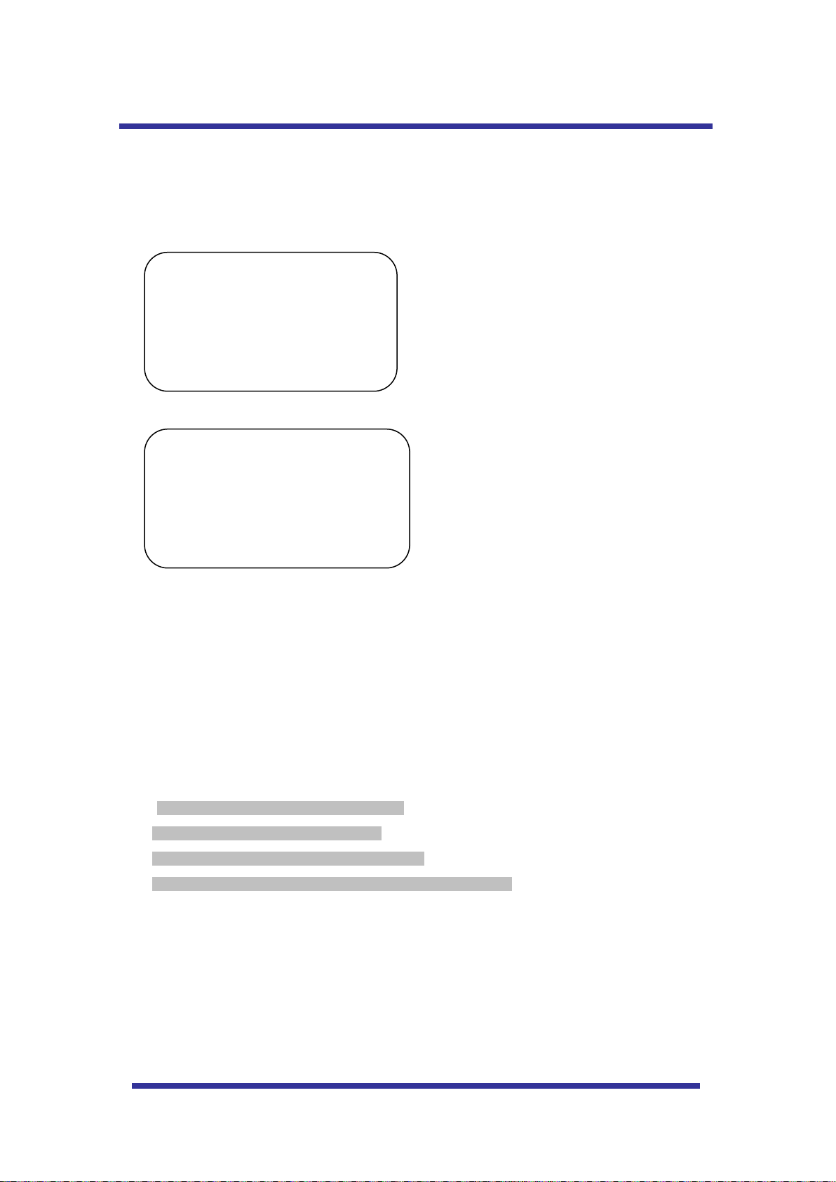
WARNING & CAUTION
If you fail to read this information and
handle the product incorrectly, death or
serious injury may occur.
1. Camera
2. Screws ( Ø4x16 screw 5EA )
3. Terminal block (5pin 2EA)
4. Manual
5. Screw Cap (2 EA)
The unit should be installed by the trained
Always stop using when the product emits
smoke or abnormal heat.
Never install the product in area exposed to
water, oil or gas.
Never install the product on a ceiling that
cannot hold its weight.
Never touch the power cord with wet hands.
Clean only with dry cloth.
Never install the product in extreme high or
low temperature.
Never drop hit strongly nor vibrate the
product.
Never expose the product to direct sunlight
or severe ray.
Never touch the front glass of the product.
Never install the product in areas exposed to
rain or water
What’s in the Box ?
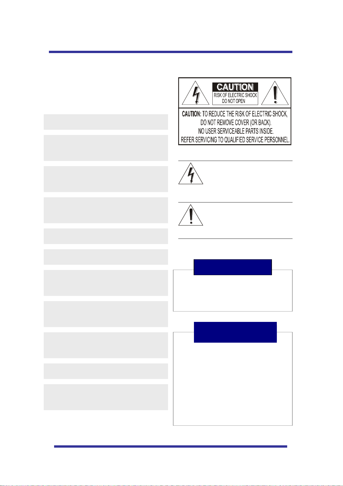
This symbol is intended to alert the user to
the presence of un-insulated “dangerous
voltage” within the product’s enclosure that
may be of sufficient magnitude to
constitute a risk of electric shock to
persons.
This symbol is intended to alert the user to
the presence of important operating and
maintenance (servicing) instructions in the
literature accompanying the appliance.
Never move Pan/Tilt by hands. It may
causes serious damage to the camera.
Warning
Page 4

4
GENERAL FEATURES
100X Zoom Mini Speed Dome
10X Optical Zoom with 10X digital zoom
±0.02° dome system accuracy with 1/4
micro step
With 0.1° technical accuracy, camera provides excellent
sensitive and delicate controlling on preset mode by
adapting 1/4 micro step and twin gear system
360° Endless Rotation
10X mini speed dome is capable of endless rotation of 360
degrees
Compensation function: preset position
The function provides absolute preset position even if the
camera is moved by low-frequency vibration, wind and any
impact.
Over 200°/Sec Preset Speed
The 360° full pan function moves through a maximum of
200°/sec., enabling you to quickly pinpoint the spot you
want to watch. Tilt speed provides through a maximum
200°/sec on preset.
Polarity Protection of Power (DC12V)
This protection function prevents the power board from
being out and trouble when power source falsely connects
to the power terminals.
Filter changeable True Day/Night
Surveillance with optimum picture is possible owing to filter
changeable Day/Night (ICR block filter) function and DSS.
Auto IR cut filter removable function is auto controlling the
operation such as color picture plus infrared cut filter during
the day and black and white picture plus filter elimination at
night.
Indoor / Outdoor applications
Compact and minimize dome size provides various install
application to big shop, shopping center, airport, highway
and so on.
Quick Operation Keys
This camera provides quick functional keys in other to be
easily controlled by any other controller or DVR.
Various Surveillance Functions
Auto Scan repeats pan and tilt between two preset
positions with different speed and dwell time.
8 Group Tour up to 8 Programmable Group tours
available and each group is consisting up to 60 presets
step with different speed and dwell time with 16
characters.
165 Preset positions up to 165 programmable
preset positions are available with 16 characters
8 Patterns up to 8 programmable user-defined patters
are available with 16 characters and each one is
consisting 50 seconds, total 400 seconds.
8 Sectors up to 8 programmable user-defined sectors
are available with 16 characters
4 Privacy Masking Zones up to 4 programmable
user-defined privacy masking zones are available with
16 characters
4 Alarm input up to 4 alarms activate with preset,
tours, patterns.
150°/S – Manual speed
This camera provides up to 150°/sec of manual speed
and it’s adjustable from 100°/sec to 150°/sec by each
10°/sec
1/4” Sony Super HAD CCD
Equipped with Sony Super HAD CCD technology, these
particular camera provide excellent sensitivity and low
smear levels.
Intelligent Pan/Tilt Controlling
Intelligent Pan/Tilt function is continually decreases pan
and tilt speeds in proportion to zoom.
Aluminum case and PC cover
Elegance designed aluminum body and Poly
Carbonated dome cover prevent weather proofed install
environment (IP66 Rated)
.
Password Protection
Page 5
5
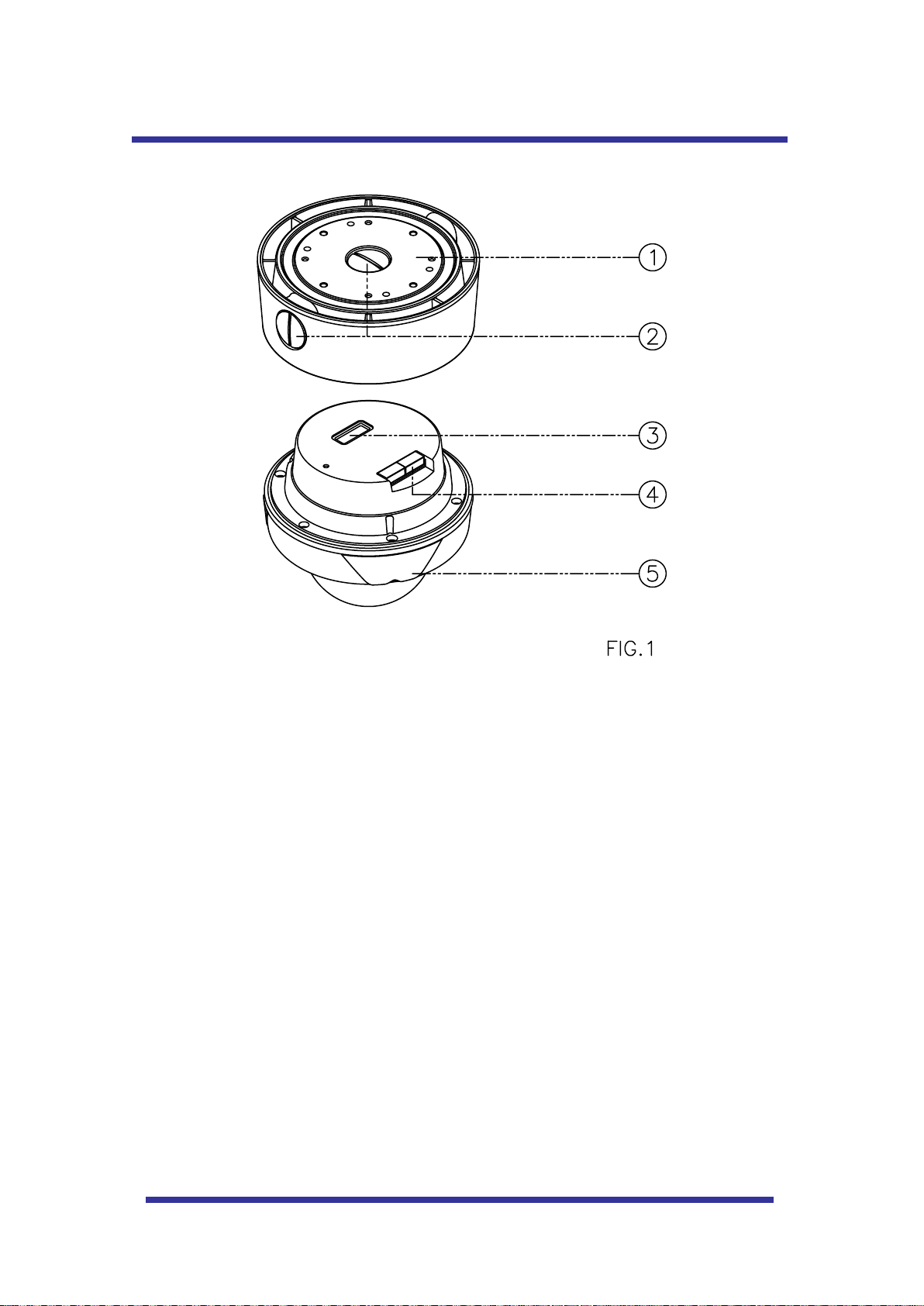
NAMES OF EAC H PAR T
1. Surface Mount Adaptor
2. Cap Screw ( PT3/4 , 2EA )
3. Dip Switch
4. Terminal Block
5. Main body
Page 6
6
INSTALLATION
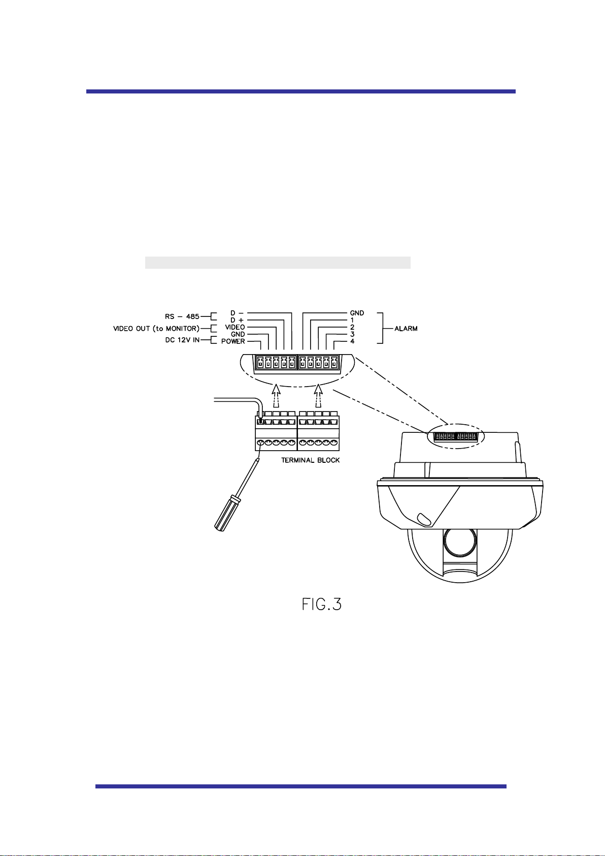
A. CONNECTION MATHOD
A-1
1. Loose the screws on the domes cover and remove it from the base.
(Screws won’t be removed)
2. Loose the screws which connect mount cover and Main base and separate dome cover from the
main base. (Screws won’t be removed)
3. Connect power (DC12V 1.5 A) to Power and GND.
4. Connect video to Video and GND.
5. Connect communication cable to RS-485 connectors.
6. Connect alarm cable to GND like 1 and GND, 2 and GND, 3 and GND, 4 and GND.
(You can use both N.O / N.C methods.)
Don’t screw too tightly. It can be the cause of defect.
Page 7
7
INS TALLATION
INSTALLATION
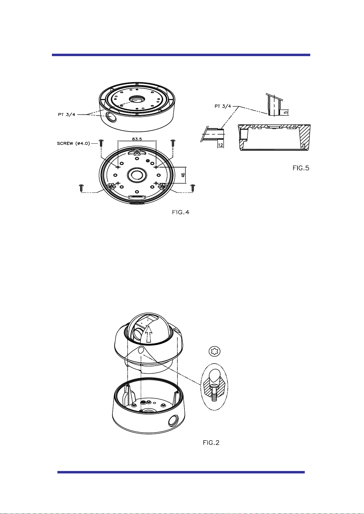
B. CEILING MOUNT TYPE
1. Fix the surface mount adaptor with 4pcs of screws on the place where you want to
install. (FIG.4)
2. When you use pipe, please note the standard size of pipe. (FIG.5)
3. You can re-assemble the domes.
Page 8
8
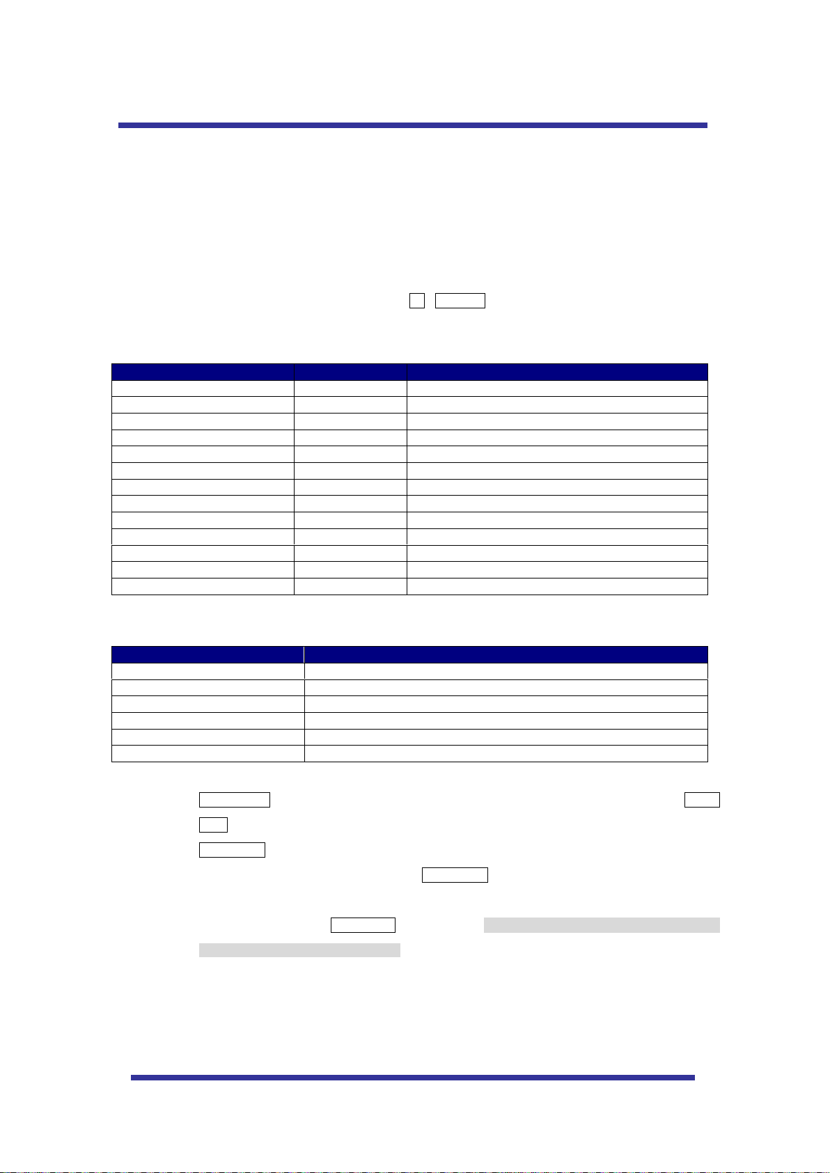
Number
Note
Function
1 ~ 64, 100~200 +Preset
PRESET
Executing Preset 1 ~ 64
65 + Preset
PRESET STATUS
Display Preset Status
66 +Preset
AUTO SCAN
Executing Auto Scan
67 +Preset
AUTO FLIP
Selectable On/Off/Auto in Auto Flip function
71~78 +Preset
GROUP TOUR
Executing Group Tour #1 ~ #8
81~88 +Preset
PATTERN
Executing Pattern #1 ~ #8
91 + Preset
ZERO POSITION
Searching Pan / Tilt Zero Position
92 + Preset
FREEZE
Select Freeze image when camera is working
93 + Preset
BLC MODE
Selectable On/Off in BLC function
94 + Preset
D/N MODE
Selectable Day/Night Mode (Auto/Day/Night Mode)
95 + Preset
OSD MAIN MENU
To enter OSD Main Menu
96 + Preset
FOCUS ADJUST
Focus adjusting
97 +Preset
ALARM
Selectable Enable/Disable all Alarms
Menu
Function
Tilt Up / Down
Sub menu cursor moves up / down
Pan Left / Right
Enter to the sub menu or status change or decrement
Focus Near
Using for Enter key when user select YES or NO
Focus Far
Using for function changing keys when set coordinate
Zoom Tele
Status cursor to the right
Zoom Wide
Status cursor to the left
QUICK OPERATING KEYS
This dome provides three protocols mainly as Pelco D, Pelco P.
These protocols are able to use with other DVR or Controller if the equipment has the above protocols.
Default setting of this dome is Pelco D / P (auto detection) with 2400 bps (baud rate).
As the merit of this product, it has lots of function keys to support the following functions.
1-64 + preset and 100~200 + preset are used for preset and 65-99 + preset used for functions.
For example, to enter OSD MENU, press the button 95 +PRESET.
<Quick Operation Key Table 1, Pelco - D, P>
<Quick Operation Keys Table 2> Use these function keys if controller has these keys>
65 + preset:” Status Report” is displayed, if user wants to remove this screen, press Focus
Near button.
92 + preset: This feature is possible to freeze the current monitoring image during tour, auto
scan or pattern operation. When press 92 + preset button, the image is suddenly freeze but
the camera is still working as per operation such as tour, pattern or auto scan. To return
operating image, press 92 + preset button again. This feature is operating by preset number
but not included in OSD main menu.
Due to Zoom camera module, OSD Menu provides not every feature. In this case, “Not
available” is displayed on the monitor.
Page 9
9
DIAGNOSTIC
CAMERA ID : 001
BAUD RATE : 2400 BPS
WAITING………
PAN ORIGIN TEST OK
TILT ORIGIN TEST OK
TX CONNECTION TEST OK
CAMERA COMM TEST OK
QUICK OPERATING KEYS
When Power on, DIAGONOSTIC is operated.
The following messages are displayed on the monitor.
A. Pan Origin Test
Zero point of Pan is founded after Panning test.
B. Tilt Origin Test
Zero point of Tilt is founded after Tilting test.
C. TX connection Test
Countdown from 60 seconds for TX Connection Test,
During 60 seconds, the camera must receive a signal from any keys of controller or DVR s.
When received the correct signal, OK is displayed after TX CONNECTION TEST.
* If “No Tested” is displayed on the monitor,
- Camera did not receive the any signal.
- Camera did receive the signal but not correct it.
- User should check protocol, baud rate and RS-485 connection.
D. Camera Comm. Test
Communication test with the camera is automatically checked.
OK should be displayed in these four tests before installation.
If all the above Tests are OK, “NOW EEPROM CHECKING” and “ALL DATA INITIALIZING” is displayed
and the camera is ready to operate.
Page 10
10
OSD MENU SETTING
MAIN MENU
DOME SETUP
CAMERA SET
AUTO SCAN
TOUR
PRAVACY
PATTERN
ALARM
SECTOR
EXIT
DOME SET
CAMERA ID : CAM1□□□□□□□□□□□□
RECOVER : OFF
MANUAL SPEED : 100°/S
AUTO FLIP : OFF
ZOOM SPEED : FAST
ALARM : DISABLE
LANGUAGE : ENGLISH
[NEXT PAGE]
SAVE AND EXIT
CAMERA SET
FLICKER : OFF/ON
MIRROR : OFF/ON
D ZOOM : OFF/ON
WB MODE : AWB MODE
PIC FLIP : OFF/ON
BLC : OFF/ON
D/N MODE : AUTO
DSS MODE : OFF/ON
EXIT
PRESET SET
PRESET NO: 001
PRESET ID: PRESET01□□□□□□□□□
PAN:XXX.X.XX.X TILT:XXX.X.XX.X
SAVE
EXIT
AUTO SCAN SET
START ANGLE : XXX.X.XX.X
END ANGLE : XXX.X.XX.X
DIRECTION : CW
ENDLESS : OFF/ON
SPEED : QUICK
DWELL TIME : 03
SAVE AND EXIT
EXIT
SECTOR SET
SECTOR NO : 01
SECTOR ID : SECTOR01□□□
SECTOR START: XXX.X.XX.X
SECTOR END : XXX.X.XX.X
SAVE
EXIT
PATTERN SET
PATT NO. : 01
PATT TITLE PATTERN01□□□
DATA FILL : 100%
SAVE
EXIT
ALARM SET
ALARM NO. : 01
ALARM INPUT : OFF
ALARM ACT : 01
SAVE
EXIT
PRIVACY SET
PRIVACY NO. : 01
DISPLAY
ACTION
SAVE
EXIT
TOUR SET
TOUR NO. : 01
TOUR TITLE : TOUR01□□□□□□
TOUR STEP : 01
PRESET NO : 01
DWELL TIME : 10
SPEED : 200°/S
SAVE AND EXIT
EXIT
NEXT PAGE
[OSD DISPLY]
[SYSTEM STATUS]
[INITIALIZATION]
[PREVIOUS PAGE]
[INITIALIZATION]
[TOUR CLEAR]
[PRESET CLEAR]
[SECTOR CLEAR]
[PRIVACY CLEAR]
[PATTERN CLEAR]
[LOAD OPTIMIZED DEFAULT
[REVIOUS PAGE]
[SYSTEM STATUS]
PROTOCOL : PELCO D,P
BAUD RATE: 2400BPS
FIRMWARE VER.:2.00
UPGRADED DATE: 06.28,06
CAMERA MODULE: SDM100
[PREVIOUS PAGE]
OSD DISPLAY
CAMERA ID: OFF/ON
PRESET ID: OFF/ON
SECTOR ID: OFF ON
COORDINATE:ON/OFF
[PREVIOUS PAGE]
A. OSD MENU TABLE
Page 11

11
DEFAULT SETTING
MAIN MENU
DOME SETUP
CAMERA SET
AUTO SCAN
TOUR
PRAVACY
PATTERN
ALARM
SECTOR
EXIT
DOME SET
CAMERA ID : CAM1□□□□□□□□□□□□
RECOVER : OFF
MANUAL SPEED : 100°/S
AUTO FLIP : OFF
ZOOM SPEED : FAST
ALARM : DISABLE
LANGUAGE : ENGLISH
[NEXT PAGE]
SAVE AND EXIT
EXIT
OSD MENU SETTING
To enter OSD Menu, press the button 95 + PRESET.
* Use the joystick “up down” to move the position and “left right” to make selection
B. Dome Setup
In order to enter Dome setup, the joystick move to right direction when cursor on dome setup.
B-1. DOME SET - CAMERA ID
To set camera ID, select up to 16 characters using Joystick to the left or right.
Press ZOOM TELE button to move to the next character from left to right direction and
ZOOM WIDE button to move to the next character from right to left direction
(Space displays when appears)
Page 12

12
OS D MENU S ETTING
DOME SET
SYSTEM LOCK: : OFF
[PASS WORD]
[OSD DISPLAY]
[SYSTEM STATUS]
[INITIALIZATION]
[PREVIOUS PAGE]
DEFAULT SETTING
B-2. DOME SET - RECOVER
This feature allows the dome to work from the last setting before you use the dome manually
(Auto scan, group tour, preset, pattern or sectors), after the set time, even power shut down and it
turns on again. Recover time can be programmed from 15 second to 99 seconds. The default
setting is OFF.
B-3. DOME SET - MANUAL SPEED
Manual Speed of Pan/Tilt is selectable from 100°/sec up to 150°/sec. The default setting is
100°/sec
B-4. DOME SET - AUTO FLIP
Auto Flip is available and the default setting is OFF. Move joystick “right or left” to select ON or
OFF. The default setting is OFF. This function can be recalled by pushing 67+ preset button.
B-5. DOME SET – ZOOM SPEED
Zoom speeds are selectable FAST or SLOW mode. Move joystick to the right direction for
selecting FAST or SLOW. The default setting is FAST.
B-6. DOME SET – ALARM
All alarms are available after set as ENABLE Mode. Move joystick to right or left direction for
selecting ENABLE/DISABLE. The default setting is DISABLE. This function can be recalled by
pushing 97 + preset button.
B-7. DOME SET - LANGUAGE
Multiple languages are selectable here including English, Italian and Polish. Move joystick to the
right or left direction to select language. The default setting is ENGLISH.
B-8. DOME SET – [NEXT PAGE]
B-8-1. DOME SET – [NEXT PAGE] – SYSTEM LOCK
Password protection provides keeping memorized data. It cannot be adjusted by anybody without
password. In order to enter [PASS WORD] page, system lock status is must set as ON. Move
joystick to right or left direction to select ON. The default setting is OFF.
Page 13

13
OSD MENU SETTING
ENTER PASSWORD
BY ENTERING PRESET CODE
PASSWORD ***
CONFIRM ***
ENTER PASSWORD
BY ENTERING PRESET CODE
PASSWORD ***
CONFIRM ***CANCELLED
ENTER PASSWORD
BY ENTERING PRESET CODE
PASSWORD ***
CONFIRM ***CONFIRMED
B-8-2. DOME SET – [NEXT PAGE] – [PASSWORD]
To enter this page to set a password, move joystick to the right direction. The password must be set
by preset number from 001 to 255 (Default 99)
A. OSD MAIN MENU TABLE (PAGE 14) default setting is BLANK.
Press any number from 001~255 with preset button on password blank and again it on confirm
blank. Then “CONFIRMED” is displayed on the monitor and the menu will go back to the previous
page automatically.
<CONFIRMED> <CANCELLED>
If user press wrong preset number between PASSWORD and CONFIRM, “CANCELLED” is
displayed on the monitor and the menu will return to the previous page automatically if user failed 3
times.
* After set a Password, the operator must press memorized password in order to enter OSD MAIN
MENU, or to change the data which is memorized originally.
* The operator must remember the password for the operation and manufacturer provides not
memorized password.
B-8-3. DOME SET – [NEXT PAGE] – [OSD DISPLAY]
OSD ID displayed after set ON in here and it can be hiding if selected OFF. Move joystick to the
right or left direction in order to select OFF/ON when the cursor is located each item.
Page 14

14
OSD DISPLAY
CAMERA ID : OFF
PRESET ID : OFF
SECTOR ID : OFF
COORDINATE : ON
[PREVIOUS PAGE]
DEFAULT SETTING
SYSTEM STATUS
PROTOCOL : PELCO D, P
BAUD RATE : 2400 BPS
FIRMWARE VER. : 1.05
UPGRADED DATE : 06.12.04
CAMERA MODULE : SDM100
[PREVIOUS PAGE]
INITIALIZATION
[TOUR CLEAR]
[PRESET CLEAR]
[SECTOR CLEAR]
[PRIVACY CLEAR]
[PATTERN CLEAR]
[LOAD OPTIMIZED DEFAULT]
[PREVIOUS PAGE]
DEFAULT SETTING
OSD MENU SETTING
B-8-4. DOME SET – [NEXT PAGE] – [SYSTEM STATUS]
This page shows the information of this camera.
- Protocol and baud rate are shown according to the dip switch setting
(Refer to page 29, 30 and 31)
- Firmware version and upgraded date will be changed if upgraded.
- Below camera modules can be set as follows.
SDM100 : SAMSUNG 10X ZOOM CAMERA MODULE.
EN300 : OPTICAL 3X MODULE (PAN FOCUS)
B-8-5. DOME SET – [NEXT PAGE] – [INITIALIZATION]
To clear all memorized data for tour, preset, sector, privacy or pattern, move joystick to the right
direction when the cursor is on [INITIALIZATION]
Page 15

15
TOUR CLEAR
ARE YOU SURE? YES NO
TOUR CLEAR
LOAD OPTIMIZED DEFAULT
ARE YOU SURE? YES NO
ALL DATA INITIALIZING
OSD MENU SETTING
- To clear memorize any data, move joystick to the right direction when cursor is on each
item.
Press FOCUS NEAR button when the cursor is at YES in order to clear memorized data. Then
flickered each item such as tour, preset, sector and so on is displayed on the monitor about 2~3
seconds. After this process, the menu is returned to the previous page.
* [PRESET CLEAR], [SECTOR CLEAR], [PRIVACY CLEAR], [PATTERN CLEAR] are same as
[TOUR CLEAR].
- To clear all data and wants returning to factory default, move joystick to the right direction when
cursor is at [LOAD OPTIMIZED DEFAULT] to enter the above page.
- Move joystick to the right or left direction in order to select YES, press FOCUS NEAR button.
- Then “ALL DATA INITIALIZING” is displayed about 5~7 seconds and then the menu are returned
to the previous page automatically.
B-9. DOME SET – [NEXT PAGE] – SAVE AND EXIT
To saving the memorized data and escape this page, move joystick to the right direction
when cursor is at SAVE AND EXIT.
B-10. DOME SET – [NEXT PAGE] – EXIT
In order not to save any data and wants to escape this page, move joystick to the right
direction when cursor is at EXIT
Page 16

16
CAMERA SET
FLICKER : OFF
MIRROR : OFF
APERTURE : 10
D ZOOM : OFF
WB MODE : AWB MODE
PIC FLIP : OFF
BLC : OFF
D/N MODE : AUTO
DSS MODE : OFF
EXIT
OSD MENU SETTING
CAMERA SET
FLICKER : OFF
BLC : OFF
EXIT
C. CAMERA SET
<10X > < 3X >
C-1. CAMERA SET - FLICKERLESS
Flickerless feature is selected between 50Hz and 60Hz. The default setting is OFF (NTSC: 60Hz /
PAL: 50Hz). Set flicker mode ON when power source is in discord with frequency. The default
setting is OFF
C-2. CAMERA SET - MIRROR
This feature shows left and right exchanged picture image like mirror. The default setting is OFF.
C-3. CAMERA SET – APERTURE
Aperture enhances picture details by increasing gain of the caemra and sharpens the edges in the
picture. The default seeting is 10. (the aperture level is from 01 ~ 15)
C-4. CAMERA SET – D ZOOM
Move joystick to the right direction in order to set as ON, if Digital Zoom is necessary at install field.
The default setting is OFF.
C-5. CAMERA SET – WB MODE
White balance functions have 4 modes according to the condition of exterior lighting. The default
setting is AWB and it may change the mode option accoding to the lighting conditions as below.
AWB Mode – 3,200°K to 6, 000°K (Default)
Indoor – up to 3,200°K
Outdoor – up to 5,800°K
ATW Mode - 2,000°K to 10, 000°K
Page 17

17
OSD MENU SETTING
C-6. CAMERA SET – PIC FLIP
Picture flip feature provides the top and down exchanged picture image horizontally. Move joystick to
the right or left direction to select OFF/ON. The default setting is OFF.
C-7. CAMERA SET – BLC (Back Light Compensation)
The default setting is OFF and BLC modes can be OFF/ON.
OFF – Backlight compensation is not activated.
ON – Back light compensation is activated.
This function can be recalled by pushing 93 + preset button.
C-8. CAMERA SET – D/N MODE
ICR filter is changeable according to the lighting, AUTO – NIGHT MODE – DAY MODE.
The default setting is AUTO MODE. This function can be recalled by pushing 94 + preset button.
C-9. CAMERA SET – DSS MODE (DIGITAL SLOW SHUTTER)
If DSS turns on, digital slow shutter is working. Per second, the electronic shutter will remain open
to receive some more lighting.
The default setting is OFF.
C-10. CAMERA SET – EXIT
To escape this page, move joystick to the right direction.
Page 18

18
PRESET SET
PRESET NO :001
PRESET ID :PRESET001------PAN :XXX.XX TILT : XXX.XX
SAVE
EXIT
DEFAULT SETTING
OSD MENU SETTING
D. PRESET SET
To enter PRESET SET, move joystick to the right direction.
D-1. PRESET – PRESET NO.
Up to 165 numbers of preset positions are available. Move joystick to the right or left direction to
select preset no.
D-2. PRESET – PRESET ID
To set preset ID, select up to 16 characters using Joystick to the left or right.
Press ZOOM TELE button moves to the next character from the left to the right direction and
ZOOM WIDE button moves to the next character from the right to left direction
(Space displays when appears)
D-3. PRESET – PAN: XXX.X TILT: XX.X
Press FOCUS FAR button in order to set preset position then, use the joystick to the position
where memorized preset no. is needed. Then press FOCUS FAR button again after setting a
preset location.
D-4. PRESET – SAVE
Move joystick to the right direction when the cursor is at SAVE and then the cursor will be located
on Preset ID for the continuous preset No. setting.
D-5. PRESET – EXIT
To escape this page, move joystick to the right direction.
Page 19

19
OSD MENU SETTING
AUTO SCAN SET
START ANGLE : XXX.X.XX.X
END ANGLE : XXX.X.XX.X
DIRECTION : CW
ENDLES : OFF
SPEED : 10°/S
DWELL TIME : 03
SAVE AND EXIT
EXIT
DEFAULT SETTING
E. AUTO SCAN SET
* 66 + preset button is working as AUTO SCAN after setting.
E-1. AUTO SCAN – START ANGLE
To set start angle, press FOCUS FAR button then move joystick to the starting angle which is needed
memorized. To press FOCUS FAR button again is to escape.
E-2. AUTO SCAN – END ANGLE
To set end angle, press FOCUS FAR button then move joystick to the starting angle which is
needed memorized. To press FOCUS FAR button again is to escape.
E-3. AUTO SCAN – DIRECTION
Auto Scan directions are available with two direction as CW or CCW by joystick to the right or left
direction
CW: Clock wise direction (Default)
CCW: Count Clock Wise Direction.
E-4. AUTO SCAN – ENDLESS
Auto Scan can use endless rotation, move joystick to the right direction in order to select ON.
Otherwise, the default setting is OFF.
E-5. AUTO SCAN – SPEED
User can use auto scan speed from 05°/S up to 35°/S and the default setting is 10°/S.
E-6. AUTO SCAN – DWELL TIME
To select dwell time, move joystick to the left or right direction in order to adjust dwell time. Possible to
set from 01 second to 30 seconds and the default setting is 03 seconds.
E-7. AUTO SCAN – SAVE AND EXIT
To saving the memorized data and escape this page, move joystick to the right direction
when cursor is at SAVE AND EXIT.
E-8. AUTO SCAN – EXIT
To escape this page, move joystick to the right direction.
Page 20

20
OSD MENU SETTING
TOUR SET
TOUR NO : 01
TOUR TITLE : TOUR01□□□□□□□□□□
TOUR STEP : 01
PRESET NO. : 01
DWELL TIME : 03
SPEED : 200°/S
SAVE
EXIT
DEFAULT SETTING
F. TOUR SET
8 Programmable tours can be set and each tour is available to set up to 64 preset steps. After setting
the data to the each tour group, 71~78 + preset buttons are working as group tour # 1~8
F-1. TOUR SET – TOUR NO.
Max. 8 group tour no. set by the joystick are available.
F-2. TOUR SET – TOUR TITLE
To set tour title, select up to 16 characters using Joystick to left or right.
Press ZOOM TELE button to move the next character from the left to the right direction and ZOOM
WIDE button to move the next character from the right to left direction (Space displays when
appears) Tour title is not displayed on the monitor, but only for the reference of user.
F-3. TOUR SET – TOUR STEP
Each tour group consists of up to 60 preset steps with different dwell time and speed. It is possible
to match any preset # for each tour step.
F-4. TOUR SET – PRESET NO.
The decided tour step #1 ~64, it is possible to select any preset no. up to 64. The default setting
is BLK
F-5. TOUR SET – DWELL TIME
Dwell time provides up to 99 seconds from 01 second. The default setting is 03 seconds.
F-6. TOUR SET – SPEED
Each tour step can be set with different tour speed up to 200°/S and it is selectable from 10°/S.
Move joystick to the right or left direction to select tour speed. The default setting is 200°/S.
F-7. TOUR SET – SAVE
To save the memorized data and escape this page, move joystick to the right direction when
cursor is at SAVE
F-8. TOUR SET – EXIT
To escape this page, move joystick to the right direction
Page 21

21
OSD MENU SETTING
PRIVACY SET
PRIVACY NO : 01
DISPLAY : OFF
ACTION : MOVE
SAVE
EXIT
DEFAULT SETTING
OSD MENU SETTING
G. PRIVACY SET
4 Privacy masking zones are available to block out areas of security.
G-1. PRIVACY SET – PRIVACY NO.
It provides up to 4 privacy masking zones
G-2. PRIVACY SET – DISPLAY.
Move joystick to the right or left direction to set ON in order to show the selectable block in the
center of the monitor. This block appears as a translucent square with blue color after set ON.
The default setting is OFF.
G-3. PRIVACY SET – ACTION (MOVE / ADJUST)
To set the blocking area, press FOCUS FAR button when the MOVE MODE is appeared. Then
use the joystick to the user defined area in order to set blocking area. Then press FOCUS FAR
button again to escape from MOVE MODE.
To adjust size of blocking area, move joystick to the right or left direction when the cursor is on
ACTION. After changed to ADJUST MODE, press FOCUS FAR button in order to adjust the size of
blocking area. The size of blocking area can be adjustable by using joystick up down or left right.
After adjusting size of blocking area, press FOCUS FAR button to escape ADJUST mode.
ADJUST: You can change the masking size by using joystick to the left or right direction
MOVE: You can move the masking area by using joystick to the left or right direction (Default)
G-4. PRIVACY SET – SAVE
After setting the privacy masking zone, to save the data, move joystick to the right direction when
the cursor is on SAVE. After saving the data, the cursor moves to PRIVACY NO.2 automatically to
prepare the next privacy masking zone.
G-5. PRIVACY SET –EXIT
To escape this page, move joystick to the right direction
H. PATTERN SET
Page 22

22
PATTERN SET
PATT NO : 01
PATT TITLE: PATTERN01□□□□□□□
DATA FILL : 0%
SAVE
EXIT
DEFAULT SETTING
OSD MENU SETTING
8 programmable patterns are available with 16 characters of title.
After setting the data to each pattern # 1~8, 81~88+ preset buttons are working as Pattern # 1~8.
H-1. PATTERN SET –PATT NO.
Up to 8 programmable user-defined patterns set by the joystick are available.
H-2. PATTERN SET –PATT TITLE
To set PATTERN TITLE, select up to 16 characters using Joystick to the left or right.
Press ZOOM TELE button moves to the next character from the left to the right direction and
ZOOM WIDE button moves to the next character from the right to left direction (Space displays
when appears) Pattern title is not displayed on the monitor, but only for the reference of user.
H-3. PATTERN SET –DATA FILL
To fill the programming data, press FOCUS FAR button in order to start the data fill up. Filling data
is programmed according to the joystick movement. Press FOCUS FAR button again in order to
escape.
H-4. PATTERN SET –SAVE
To saving the filling data, move joystick to the right direction when the cursor is on SAVE. Then the
cursor moves to the PATT NO.02 in order to prepare next pattern no.
H-5. PATTERN SET –EXIT
To escape this page, move joystick to the right direction
I. ALARM SET
Page 23

23
ALARM SET
ALARM NO : 01
ALARM INPUT: OFF
ALARM ACT : 001
SAVE
EXIT
DEFAULT SETTING
4 Alarm inputs are available and each alarm is activating to presets, group tours or patterns.
I-1. ALARM SET – ALARM NO.
Up to 4 alarms are selectable by using joystick to the right direction when cursor is on ALARM NO.
I-2. ALARM SET – ALARM INPUT
Input alarm ways provide two different ways as NC (Normal Close) or NO (Normal Open)
The default setting is OFF
I-3. ALARM SET – ALARM ACT
Alarm activates various surveillance modes with Preset number up to 165, Group tour up
to 8, Pattern up to 8. Move joystick to the right or left direction to select any preset
number, group tour no. or pattern no.
I-4. ALARM SET – SAVE
After setting the alarm input ways and activation, to save the data, move joystick to the right
direction when the cursor is on SAVE. After saving the data, the cursor moves to Alarm NO.2
automatically to prepare the next alarm.
I-5. ALARM SET –EXIT
To escape this page, move joystick to the right direction
* Before activating Alarm, user must set ALARM ENABLE at DOME SET – ALARM – ENABLE
(Refer to page 15)
Page 24

24
OSD MENU SETTING
SECTOR SET
SECTOR NO : 01
SECTOR ID: SECTOR01□□□□□□□□
SECTOR START: XXX.X.XX.X
SECTOR END : XXX.X.XX.X
SAVE
EXIT
DEFAULT SETTING
Start Position
End Position
J. SECTOR SET
Up to 8 programmable sectors are available with 16 characters.
This feature is useful to memory the certain location such as parking zone or so on.
When camera goes through this area, it shows the letter you memorized.
J-1. SECTOR SET – SECTOR NO.
Up to 8 programmable sectors set by the joystick are available.
J-2. SECTOR SET – SECTOR ID
To set SECTOR ID, select up to 16 characters by using Joystick to the left or right.
Press ZOOM TELE button to move to the next character from the left to the right direction and
ZOOM WIDE button to move to the next character from the right to left direction (Space displays
when appears)
J-3. SECTOR SET – SECTOR START
To set SECTOR START angle, press FOCUS FAR button then move joystick to the left or right
direction to set the position. To press FOCUS FAR button again is to escape.
J-4. SECTOR SET – SECTOR END
To set SECTOR END angle, press FOCUS FAR button then move joystick to the left or right
direction to set the position. To press FOCUS FAR button again is to escape.
J-5. SECTOR SET – SAVE
After setting the SECTOR position, to save the data, move joystick to the right direction when the
cursor is on SAVE. After saving the data, the cursor moves to SECTOR NO.2 automatically to
prepare the next SECTOR.
J-6. SECTOR SET –EXIT
To escape this page, move joystick to the right direction
K. EXIT
To escape OSD Main Menu, move joystick to the right or left direction then this camera is
ready to operate.
Page 25

25
DIP SW
ID VALUE
DIP SW
ID VALUE
DIP SW
ID VALUE
100000XXXX
1
111010XXXX
23
101101XXXX
45
010000XXXX
2
000110XXXX
24
011101XXXX
46
110000XXXX
3
100110XXXX
25
111101XXXX
47
001000XXXX
4
010110XXXX
26
100011XXXX
48
101000XXXX
5
110110XXXX
27
100011XXXX
49
011000XXXX
6
001110XXXX
28
010011XXXX
50
111000XXXX
7
101110XXXX
29
110011XXXX
51
000100XXXX
8
011110XXXX
30
001011XXXX
52
100100XXXX
9
111110XXXX
31
101011XXXX
53
010100XXXX
10
000001XXXX
32
011011XXXX
54
110100XXXX
11
100001XXXX
33
111011XXXX
55
001100XXXX
12
010001XXXX
34
000111XXXX
56
101100XXXX
13
110001XXXX
35
100111XXXX
57
011100XXXX
14
001001XXXX
36
010111XXXX
58
111100XXXX
15
101001XXXX
37
110111XXXX
59
000010XXXX
16
011001XXXX
38
001111XXXX
60
100010XXXX
17
111001XXXX
39
101111XXXX
61
010010XXXX
18
000101XXXX
40
011111XXXX
62
110010XXXX
19
100101XXXX
41
111111XXXX
63
001010XXXX
20
010101XXXX
42
101010XXXX
21
110101XXXX
43
011010XXXX
22
001101XXXX
44
DIP SWITCH SETTING
Termination
Protocol
ID Set
Baud rate
A-1. DIP SW SETTING
Mini Speed Dome camera provides up to 63 cameras ID and it’s an adjustable ID with 1st~6th of Dip
switch.
Open the camera case to set ID using DIP SW1.
* Factory default: Camera ID = 1, PELCO-D Baud Rate: 2400bps
A-2. ID SETTING (1-ON, 0-OFF) (110)
Page 26

26
DIP SW1- 7
DIP SW1- 8
OFF
OFF
Pelco-D or Pelco-P
DIP SW1 9th
BAUD RATE
OFF
2400
ON
9600
DIP SWITCH SETTING
A-3. PROTOCOL
7th~8th dip switches are used for Protocol Setting.
Factory Default: Pelco-D or Pelco-P (Auto detection)
A-4. BAUD RATE SETTING
The 9th Dip Switch is used for BAUD RATE setting.
DIP SW can be changeable to 2400bps, 9600bps.
Factory Default: 2400bps.
.
A-5. 485 TERMINATIONS
10th Dip Switch is used for 100Ω termination.
Set on 10th Dip Switch only for the last looped camera from the controller.
Even in case of only one camera, set on 10th Dip Switch of the cameras.
Page 27

27
PROBLEM
SOLUTION
No operating
Check if the power supply is DC12V.
Check if RS-485 communication cable is connected correctly.
Check camera ID setting.
Check the termination.
No picture
Check if all the cables are connected correctly.
Check if the monitor is adjusted correctly.
Check if video signal line is cut.
Dark screen
Adjust the monitor status.
Abnormal camera
Operation status
Check if voltage level is out of the specification.
Check the termination.
Screen not clear
Check if there is dust on the lens.
Adjust the monitor status.
If excessive light is seen on a screen, change the camera
angle or location.
Adjust the lens focus again.
TROUBLESHOOTING
If you have trouble in operating in your camera, refer to the following.
Page 28

28
MODEL
10X A/F CAMERA MODULE
3X PAN FOCUS MODULE
PAN /TILT
Pan Rotation Angle
360˚ Endless
Pan Speed
Manual
100˚ ~ 150˚/sec
Preset
Max 200˚ /sec
Tilt Rotation Angle
0˚ ~ 90˚
Tilt Speed
Manual
100˚ ~ 150˚/sec
Preset
Max 200˚ /sec
System Accuracy
0.02˚
FUNCTIONS
Presets
165 positions with a 16-character label available for each position
with different speed steps
Group Tour
Max. 8 Programmable group tours (each one consisting of up to 60 preset steps
with different steps)
Auto scan
Programmable Auto scan
Pattern
8 Programmable Patterns (total 480 seconds)
Privacy Zone
4 privacy zones
-
Sector
8 selectable Sectors with 16 characters
Password Protection
Yes
Alarm Input
4 alarms OFF/NC/NO (with various programmable states)
Alarm Actions
Activate preset, Group scanning or Patterns
Auto Flip
ON / OFF
OSD Menu
Multiple Languages on screen
Communication
RS-485
Protocol
Pelco D/P
POWER
Consumption (12V DC)
9W Max (Heater Type 15W)
Consumption (24V AC)
18W Max (Heater Type 30W)
Power Supply(12V DC)
DC12V 750mA (Heater Type DC12V 1.2W)
Power Supply(24V AC)
AC 24V 650mA (Heater Type AC24V 1.3W)
OTHERS
Construction
die-casting , Anti-vandal dome cover
Dimensions
158.8φ (D) * 163.0mm(H)
Weight
1.5 kg
Motor Type
Stepper Motor
Micro Steps
1/4 Step
Storage Temperature
-10℃ ~ 60℃
Operating Temperature
0℃ ~ 50℃
Certifications
CE, FCC
CAMERA
MODULE
Image Sensor
1/4" Sony Super HAD CCD
Total
Image
Pixels
NTSC
811(H) * 508(V) 410K
PAL
795(H) * 596(V) 470K
Number Of
Effective
Pixels
NTSC
768(H) * 494(V) 380K
PAL
752(H) * 582(V) 440K
Horizontal resolution
More Than 500TV Lines
More Than 520TV Lines
Lens
Optical
10x Optical Zoom
(F=3.8 to 38mm)
3x Optical Zoom
(F=1.9~2.8, f=4.1~7.3mm)
Digital
10x (100x with optical)
-
Day & Night (ICR)
Auto/ Day/ Night
-
Min. Shooting Distance
0.35m(Wide)/0.8m(Tele)
0.32m(Wide)/1.5m(Tele)
Digital Slow Shutter
2/4/8/16/24/32/64/128/ OFF
-
Min.
illumination
Normal
mode
0.7Lux (50IRE)
1.0Lux (50IRE)
Night
mode
0.02Lux (ICR On)
Luminance S/N Ratio
More than 50dB
Video Output
VBS:1.0Vp-p/75 Ohm
BLC
ON / OFF
Flickerless
NTSC
ON / OFF (1/100)
PAL
ON / OFF (1/120)
WHITE BALANCE
AWB/ATW/INDOOR/ OUTDOOR
AWB only
SPECIFICATIONS
Page 29

29
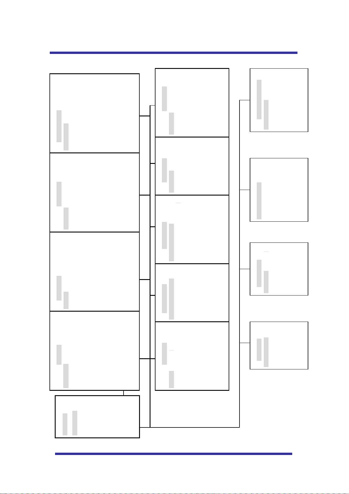
DIMENSIONS
Page 30

30
General Information
Limited Warranty
At Discount Security Cameras (DSC) we take pride in offering only the highest quality reliable products.
In the rare event that a defect does occur we offer the following warranty:
All products are warranted by Discount Security Cameras for 1 year from date of purchase, except for
Clearance items, which are warranted for 30 days. If a product is defective we will repair or replace it.
The customer is responsible for the shipping to send the product to us. We will cover the freight to return
the product back to the customer.
After 1 year we will continue to service your products for the standard labor rate (currently $45 per hourminimum 2 hours) plus parts or phone technical support for $50.00/hour.
The following situations void the product warranty: 1. Opening the housing of any camera with a fixed
lens; 2. Cutting the connectors off any equipment; 3. Adding 3rd party software to a DVR without prior
approval from our technical support department; 4. Damage caused by nature such as water flooding,
winds, lightning and other similar events; the fault of the installer or customer (for example dropping or
breaking the product, improper voltage, or improper installation) and failing to follow safety tips as
previously mentioned above.
RMA: All returns and warranty services require a valid Returned Merchandise Authorization Number
(RMA#) issued by Discount Security Cameras. Merchandise will not be honored and will be returned to
customer without RMA#. You must provide the Optiview Serial number of the unit when calling for
technical service or Return Material Authorization (RMA) number.
All returns and warranty services require a valid Returned Merchandise Authorization Number (RMA#)
issued by Optiview. RMA numbers are only valid for 14 days from date of issuance.
Technical Support
You will need to contact the vendor, where you originally purchase this Mini PTZ Camera, if you need
technical support. The Serial number of the Camera is located at the bottom of the main internal dome
camera which can be access by opening up the clear acrylic dome cover. You will need to have this ready
prior to calling our Optiview Technical support group to avoid delay or denial of support for this product.
You may also use your Order number or Invoice number as your reference prior to calling us for technical
support. You can contact us at 904-855-1121 or email us at tech@videodvr.com.
Page 31

31
Return Policy
Merchandise may be returned for a refund or exchange for 15 days from day of receipt as long as the
equipment is still in "as new" condition. A 15% restocking fee may apply. Shipping costs are not
refundable (unless the product is defective - see warrantee below).
"As New" means that all items must be undamaged and in their original cartons and packaging along with
all accessories, documentation, and parts. No wires or pigtails can be cut. The product exterior must be
intact and unmarked. The original carton must be in another "shipping" box. No postmarks or labels shall
be on the original box. Cable must be unopened (or still on reel).
A Return Merchandise Authorization (RMA) number must be obtained from Optiview prior to the return
of any merchandise. An RMA number is only valid for 14 days (returned products must be received
within 14 days from issuance of the RMA number).
Return and Warranty information may be updated or changed without prior notice.
For complete and updated information on warranty and return policy, go to
http://www.optiviewpro.com/return_warranty.htm
Camera Serial #: __________
Invoice/Order#____________ Date of Purchase: __________
 Loading...