

Page 1
USER’S MANUAL
IRPTZ22: 22X Zoom Infrared PTZ Camera
Page 2

CONTENTS
Chapter 1 Precautions ................................................................................ 3
Chapter 2 Structure ...................................................................................... 5
Chapter 3 Dome Settings ............................................................................ 7
Chapter 4 Installation Guide ................................................................... 10
Chapter 5 Functions Description ......................................................... 13
5.1 Features ........................................................................................ 13
5.2 Function Instruction ................................................................ 14
Chapter 6 Operation instruction .......................................................... 18
Page 3

Chapter 1 Precautions
● Please read this manual carefully before installation.
● Handle with care
In transportation and storage process, we need to prevent stress, such as
severe vibration, and immersion to avoid any damage to the product. This
product must be carried disassembled and packaged, either in delivery to users
or in return delivery to the factory for repairing. Damage caused by assembled
transportation will not be covered by warranty.
● Install with care
Handle the product carefully and gently. Prevent such incorrect operations as
stress, severe vibration, or may lead to mechanical failure, affecting the overall
performance of product;
Under the cover are advanced optical devices, avoid direct hand touch, for the
sake of image quality;
The electrical installation must comply with safety standards, with use of
dedicated power adapter;
Control signals and video signals should maintain a sufficient distance from
high-voltage equipment or cables in the transmission process, if necessary, take
anti-lightning, anti-surge and other protective measures. Keep power off until the
completion of all installation.
● Do not dismantle parts
Do not dismantle internal parts, please turn to qualified maintenance
professionals to carry out repairs.
● Do not put any object into the product
Make sure that there is no metal object or flammable materials inside the
1
Page 4

product. Such objects or materials may lead to fire, short circuit or damage. If
water or liquid flow into the product, turn off the power and disconnect the
power cord immediately, and then negotiate with the company. Be careful to
protect the camera. Avoid the rain, sea erosion.
● Keep the product away from electric or magnetic fields
If the product is placed near TV, radio transmitters, electromagnetic devices,
electric motors, transformers, loudspeakers in the vicinity, the electromagnetic
fields generated by them would interfere the image.
● Do not point the camera at strong light
Regardless of power on/off status, do not point the camera at the sun or very
bright objects, do not point the camera at bright stationary objects for a long time,
otherwise it will cause unrecoverable damage to the camera CCD.
● Maintenance with care
It is advised to avoid collision or vibration. Do not use strong or abrasive
detergents to clean the dome body. When cleaning up dirt, use dry cloth. if dirt is
uneasy to remove, swab with a neutral detergent. If there is sticky dust on the lens,
please use the special lens paper.
● Working Environment
Power AC 220V/0.5A
Communication port RS485
Environmental temperature -25~50℃(IR off) -25~30℃(IR on)
Moisture <95%(Non-condensing)
Atmospheric pressure 86~106KPa
Note: make sure outdoor installation meets water-proof requirements.
2
Page 5
Module Specifications:
Model IRPTZ22
Image Sensor 1/4'' Sony Super HAD CCD
Pixels 795 (H) × 596 (V)
Resolution 540 TV Lines
Video Output 1.0Vp-p Composite Video (75Ω)
Sync System Internal / External (V-Lock)
Lens 3.4~77mm (auto focus)
Zoom 22X Optical / 12X Digital
Focus Auto / Manual
Infrared Range 350 ft. (72 IR LEDs)
Minimum Illumination 0.1 Lux (ICR On)
S/N Ratio 50dB
Backlight Compensation Auto
White Balance ATW / Indoor / Outdoor / Manual / AWB / One Push WB
Gain Auto / Manual
Pan Angle 360° continuous pan rotation
Tilt Angle 90° (auto flip)
Manual Speed 0.01° ~ 120° /s
Preset Speed 120° /s
Communication Interface RS-485
Protocols Pelco P, Pelco D
Baud Rate 2400, 4800, 9600 bsp
Mount Wall Mount Only
Operating Temperature 32°F - 122°F / 0°C - 50°C
Dimensions (Diam*H) 6.9'' × 7.9'' / 175mm × 200mm
Weight (with / without bracket) 12 lbs. (5.4kgs) / 16 lbs. (7.3kgs)
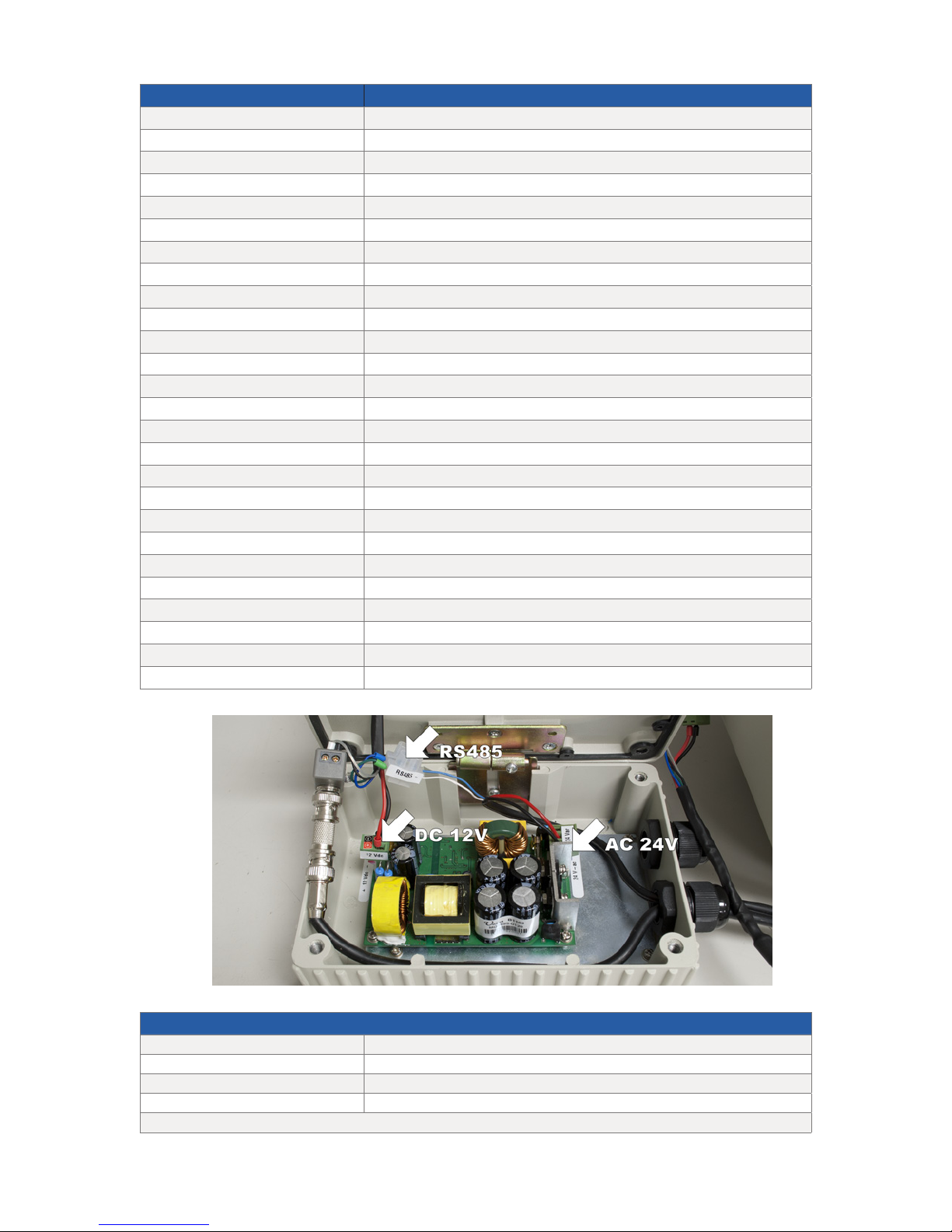
Power Supply DC 12V, 3A
Wire Harness
Gray Video+
Black Video-
Green RS485-
Blue RS485+
DIP Switch bank is located on the side of the camera labeled as “180°” cap
Page 6
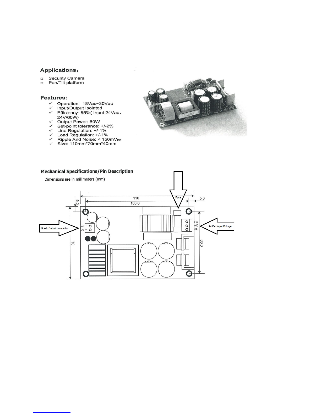
IRPTZ22 Low-voltage Power Supply
Input Voltage (in) > 18-30 V AC
Output:
Power = 60 W
Voltage = 12-18 Vdc
Line regulation = 1%
Load Regulation = 1%
Efficiency = 86%
Page 7
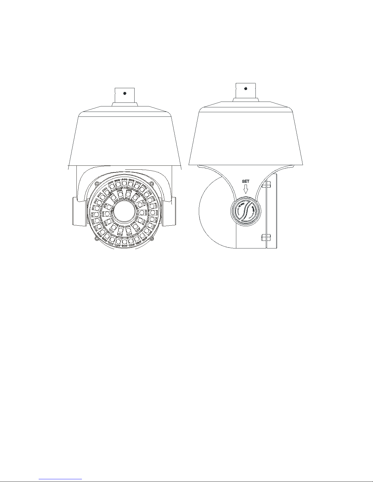
Chapter 2 Structure
Front view Side view
4
Page 8
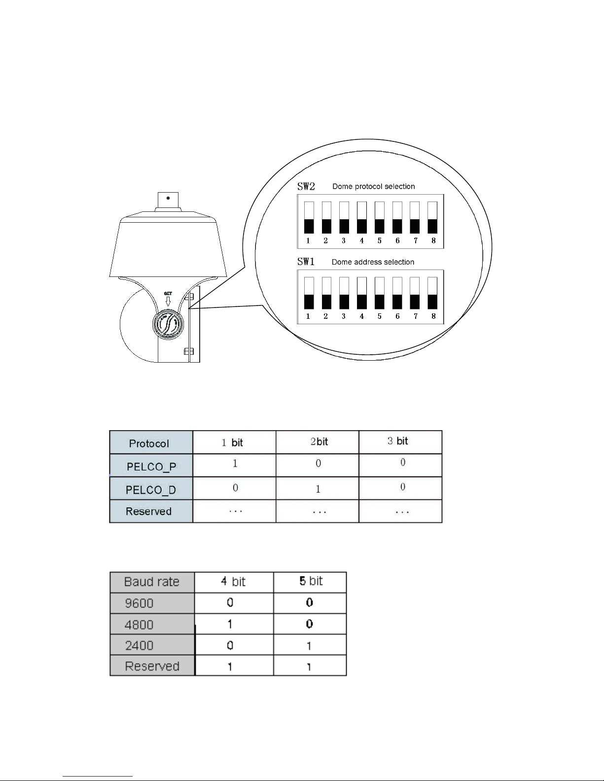
Chapter 3 Dome Settings
Protocol Setting
This product supports two protocols: PELCO-P、PELCO-D, and two baud rate:
9600BPS, 4800BPS, 2400BPS. Protocol dip switch is bit 1~3 of SW2.
Baud Rate Setting
Baud rate setting dip switch is bit 4~5 of SW2.
5
Page 9
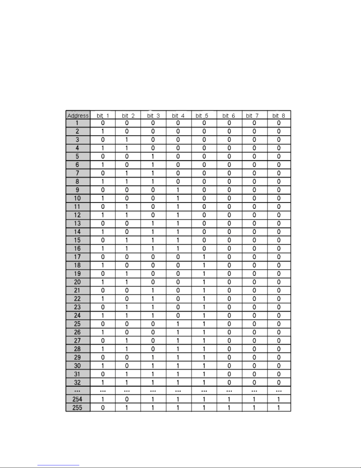
Dome Address Setting
8-bit dip switch (SW1)at dome side is for setting dome address. Dome setting
adopts binary system, the 8th bit is the highest, the 1st bit is the lowest. Total 255
dome addresses could be set.。
Dome address code table under protocol PELCO-P:
6
Page 10
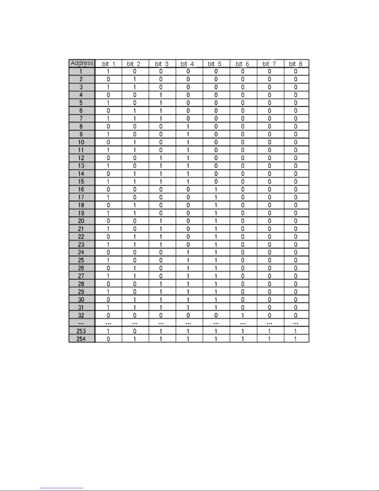
Dome address code table under protocol PELCO-D:
*Notice: 1. “1” means “on” status and “0” means “off” status.
2. Dip switch for protocol PELCO-P are the same, while dip switch for PELCO-D
is slightly different. PELCO_D protocol supports maximum 254 dome addresses.
7
Page 11
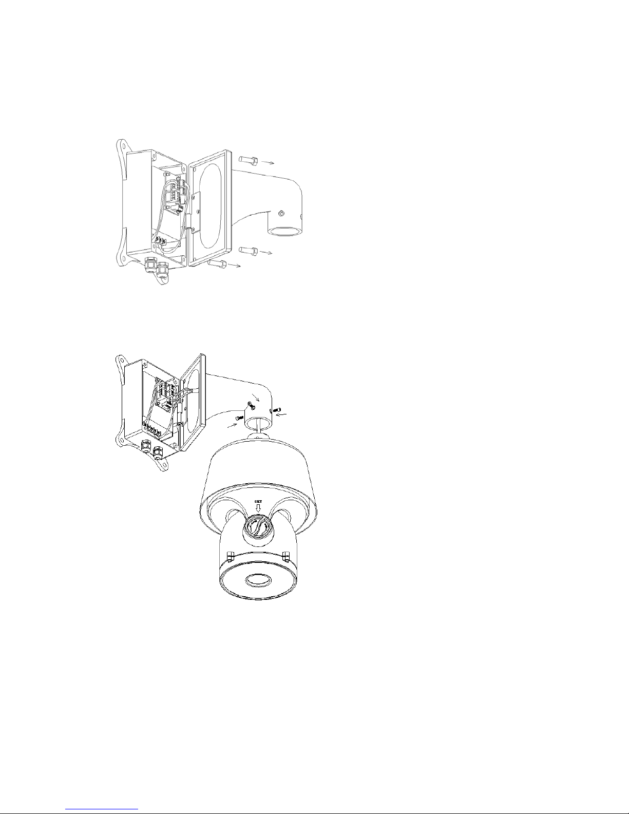
Chapter 4 Installation Guide
1、Take out the bracket and unscrew the power box from the bracket.
2、Thread cables across the bracket and connect them to the circuit board in the
power box.
Install the dome body to the bracket, screw up with 4 inner hexagon screws. If
necessary, apply water-proof glue to the joint gap.
3、unscrew the cover with the mark “SET”, set communication protocol and
addresses. Screw up again with care to avoid water.After the installation of dome
body, use two outer hexagon screws to tighten
bracket and power box.
8
Page 12
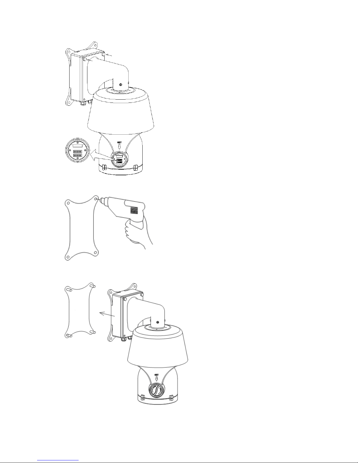
4、Attach the drill positioning paste to the wall, and drill according to the paste,
and install expansion bolts.
5、Install the dome body together with bracket and power box to the expansion
bolts, and tighten with screws.
9
Page 13

6、Remove two screws from the power box, and open it.
Thread power cable(AC220V)through the water-proof head on the left, and
RS485 and video cable through the water-proof head on the right.
Connect cables to the circuit board, double check order of connection to avoid
dam age from wrong connection.
After cable connection, tighten the two heads, if necessary, appl water-proof
glue to the heads.
7、close power box, tighten the bracket to the power box. Double check if there is
joint gaps, if necessary, apply water-proof glue.
10
Page 14

Chapter 5 Functions Description
5.1 Features
1. Built-in Decoder
● Power-off protection, no data loss
● Support both Chinese and English menu
● Support one week and eight hours each day timing operation
● Exact time display
● Built-in direction display function
● 220 programmable presets
● 8 cruising tracks, each cruising track has 32 preset positions
● 8 auto scan tracks, the left and right boundaries an scan speed can be set
● 8 privacy zones
● 4 pattern tours, each one with 180s memory
● 3D location function
● Guard location, the dome can operate preset, auto scan, cruising and pattern
tours functions after a short pause
● Support PELCO_P、PELCO_D protocols
● RS-485 bus
● Remote reset function
2. Integrated Universal Speed Change Rotator
● Delicate stepping motor, stable, sensitive and accurate
● 360°continuous pan without blind area
● Stepless speed change, auto zoom/speed matching
● Auto overturn function
● Manual Speed:0.01°~120°/s,Max cruising speed 120°/s
11
Page 15

3. Built-in High Definition Day/Night Camera
● Auto iris, auto back light compensation
● Auto/manual white balance
● Auto/manual focus
● Auto/manual brightness control
● Multiple kinds of camera for options
4. All-weather Outdoor Design
● Built-in heater
● Built-in fan, can operate in 60℃
● High Die-cast Aluminum Construction
● IP66 water proof
● 3000V lightning and surge current proof
5.2 Function Instruction
● Menu Function
Support Chinese and English menu operation
● Dome Address Setting
Support up to 256 dome addresses, and dome can be controlled by the order in
same address. The address can be set by the dial switch on decoder board.
● Privacy Protection Function
Set black areas to mask the privacy or security parts. The black areas location
can be set, and support up to 8 mask zones.
● Timing Running Function
Users can set speed dome operation task at different time during one week.
12
Page 16

● Direction Indication Function
Users can set North by themselves, and also can set indication area. When
speed dome turns to the area, the tilt will be displayed in screen.
● Motion Detection Function
For some special cameras, the dome can auto track the moving things.
● 3D Location Function
In dome effective zoom scope, can zoom in and out any area on screen, also
can move any point to center. Need work with our Matrix or DVR.
● Focus/Rotate Auto Match
Speed Dome can auto adjust pan and tilt rotation speed depending on the
focus distance.
● Auto Flip
The lens can auto flip when it rotates 180°
● Preset Position Setting and Calling
Preset function means the speed dome can memory current pan/tilt angel,
focus, zoom, ect. When need, it can be called upon directly. Our speed dome
support up to 220 preset positions.
● Auto Scan
Users can set the left and right boundaries by control keyboard. Then speed
dome can scan between it. It can set up to 8 groups scan path.
● Auto Cruising
Users can program some preset positions into auto cruising sequence, then the
13
Page 17

speed dome can track as it. Each cruising tracks has 32 preset positions.
● Pattern Tour
Speed Dome can memory 180s running path or 500 orders. When start
pattern tour, speed dome can track as recording path. It supports 4 groups pattern
tour.
● Guard Location
The dome will rotate back to preset position after a period of vacant time.
● Lens Control
1) Zoom Control
Users can control zoom by keyboard to get near or far images
2) Focus Control
System auto focus default. Also users can manually focus.
Note: can manually focus by keyboard and matrix, please refer to keyboard
or matrix user’s manual.
Camera can’t auto focus in following situation:
● Target is not in the center
● Can not guarantee clear images when watch near and far target at the same
time
● Target is light objects. Such as neon lighting, spotlights and other bright objects
● Target is behind the glass with droplets and dust.
● Target moves too fast
● Large area targets, such as walls;
● Target are too dark or inherently ambiguous;
14
Page 18

3) Auto Iris Control
Auto sense ambient light, and make quick adjustments.
4) Auto Back Compensation
In the bright background, auto compensate light for the target, and adjust the
back light.
5) Auto/Manual White Balance
Auto/Manual adjust depending on the environment light changes.
6)Day and Night Switch (Only for Day/Nigh Camera)
Speed dome camera can auto switch between color and black and white.
7)High Speed Dome Menu Setup (Only for camera with menu)
Call upon preset No.95 to enter into menu setup interface. Press “Focus” to
choose menu items and press “Iris” to set menu contents.
15
Page 19

Chapter 6 Operation instruction
The user can call upon preset position 95 to enter the setting interface of the OSD menu.
OSD Menu Tree
16
Page 20

Language
It supports two language option Chinese and English. Call upon preset
position 95 to enter the setting interface of the OSD menu and move to “language
setting”, push “ Iris on” to enter setting and move the joystick to switch
Chinese/English.
SYSTEM INFORMATION
A:DOME ID
B:DOME ADDRESS
C BAU DRAT E
D PROTOCAL
E:TV SYSTEM
F:INSIDE TEMP
DI SPLAY
Call upon preset position 95 to enter the setting interface of the OSD menu
17
Page 21

and move joystick, select “display” enter submenu of “display”.
A:DOME
Press “Iris on” to set DOME SETTING and with “ON/OFF” option.
B:PRESET
Press “Iris on” to set PRESET SETTING and with ON/OFF/2SEC/5SEC/10SEC
option.
C:AUTO
Press “Iris on” to set AUTO SETTING and with ON/OFF/2SEC/5SEC/10SEC
option.
D:ZONES
Press “Iris on” to set ZONES SETTING and with ON/OFF/2SEC/5SEC/10SEC
option.
E:DATE/TIME
Press “Iris on” to set DATE/TIME SETTING and move joystick to select
ON/OFF/2SEC/5SEC/10SEC option.
F:PAN/TILT
Press “Iris on” to set PAN/TILT SETTING and move joystick to select
ON/OFF/2SEC/5SEC/10SEC option.
Display position of setting contents on screen
Move cursor to DISPLAY POSITION and press “Iris on” to enter submenu of
18
Page 22

DISPLAY POSITION
A:DATE/TIME
Press “Iris on” to set DATE/TIME SETTING and move joystick to adjust
DATE/TIME until get best position. Press “Iris on” to confirm.
B:DOME
Press “Iris on” to set DOME SETTING and move joystick to adjust DOME until get
best position. Press “Iris on” to confirm.
C:ZONES
Press “Iris on” to set ZONES SETTING and move joystick to adjust ZONES until get
best position. Press “Iris on” to confirm.
D:AUTO
Press “Iris on” to set AUTO SETTING and move joystick to adjust AUTO until get
best position. Press “Iris on” to confirm.
E:PAN/TILT
Press “Iris on” to set PAN/TILT SETTING and move joystick to adjust PAN/TILT
until get best position. Press “Iris on” to confirm.
DOME SETTINGS
Call upon preset position 95 to enter the setting interface of the OSD menu
and move joystick to “DOME” press “Iris on” enter submenu of “DOME”.
A:IR LED SETTINGS
19
Page 23

Move the cursor to “IR LED”, and press iris open to submenu.
A1:Open Control Type
Move the cursor to “Open Control Type”, and press iris open to select IR light
control type; move the joystick to set IR light control type as “External
synchronization Auto/ Internal Synchronization Auto /Time
Schedule/Open/Close”.
Instruction of five control types:
1:External synchronization Auto:Open or close of IR LED will depend on light
sensor completely, and dome will control the day/night switch. When the light
sensor detected that the environmental light is lower than the threshold of IR LED
open, IR LED will turn on, and camera switch from color to black/white;When the
environmental light is higher than the threshold of IR LED close, IR LED will turn
off, and camera switch from black/white to color.
2:Internal Synchronization Auto: IR LED will turn on to the auto switch of
camera from
color to black/white, and turn off according to the light sensor control. When the
environmental light is higher than IR LED threshold value, IR LED will turn off and
D/N of camera recover to auto.
3:Time:IR LED will turn on or offer according to the open and close time set by
user ( 00:
00 can be set in the time period). For example:( Open time is set as 19:00,and
close time as
06:00, then the IR LED will turn on at 19:00,and close at 06:00 in the next
20
Page 24

morning)
4:Open:IR LED always on.
5:Clo s e:IR LED always off.
Note:
D/N AUTO of camera is valid, unless the dome is set as “Internal
Synchronization Auto”.
B1:Environment Threshold Value
User can adjust the environment light threshold value as to different
application locations. In External synchronization Auto type, default value is
1~2lux(there may be slight difference because of the direction of IR LED. IR LED
is on in light condition. Threshold value can be set from 1 to 10. 1 means that the
light is weak and 10 means that the light is strong.
C1:Sensitivity Setup
When the IR LED is on, environment light threshold to close IR LED delays, 1
stands for high sensitivity, and related delay range is narrow, IR LED on and off
may switch frequently in a certain light condition; 10 stands for low sensitivity,
and related delay range is wide, there is a huge light difference when IR LED on
and off. Default value is 5.
D1:Open Time
Press iris on to enter open time setup, and move joystick leftward or
rightward to select the time value you want to change and upward or downward
to change the value.
E1: Close time
Press “Iris on” to set close time and move joystick from left and right to select
clock bit, move joystick from up and down to change value.
Note: It is effective to set start time and close time of IR LED in the timing mode of
IR LED control.
F1:Zoom match
Press “Iris on” to set zoom match. When select open, illumination and power
21
Page 25

of IR LED are matched with irradiation distance of camera. With different zoom,
IR LED at its best control and adjust power automatically. When select close, start
IR LED will depends on illumination set by user and it can’t adjust automatically.
It is suggest selecting open zoom match.
G1: Illumination of light group 1
Light group 1 is outside lane long distance IR LED, press “Iris on” to set
illumination value.
H1: Illumination of light group 2
Light group 2 is centre circle medium distance IR LED, press “Iris on” to set
illumination value.
I1:Illumination of light group 3
Light group 3 is inside lane short distance IR LED, press “Iris on” to set
illumination value. When close zoom match, user should adjust irradiation
distance by himself.
Note: When open zoom match, it can’t adjust illumination of Light group 1,
Light group 2 and Light group 3 manually.
B:STANDBY SETTINGS
Move cursor to STANDBY SETTINGS and press “Iris on” to submenu of STANDBY
SETTINGS.
A1:STANDBY TIME
Move cursor to STANDBY TIME and press “Iris on” to setup time, move
22
Page 26

joystick and time can be set: 30sec/2min/5min/10min. Press “Iris on” to confirm.
B1:STANDBY MOTION
Move cursor to STANDBY MOTION and press “Iris on” to setup motion,
move joystick and motion can be set:: preset 1/scan 1/crusing tour 1/pattern
tour 1/no control. Press “Iris on” to confirm.
C:PRIVACY MASK
A1. PRIVACY MASK
Move cursor to PRIVACY MASK and press “Iris on” to setup. Move joystick to
select privacy mask and it supports 8 masks in total.
B1.ENABLE
Move cursor to ENABLE and press “Iris on” to setup switch of privacy mask. Move
joystick to select the state: on and off.
C1.SETUP
Move cursor to SETUP and press “Iris on” to setup the position of privacy mask,
press “Iris on” to confirm. Move cursor to the privacy mask, press “Iris on” to
enter the privacy size setting and move joystick to adjust size. Press “Iris on” to
confirm.
D1. CANCEL
Move cursor to CANCEL and press “Iris on” to cancel selected privacy mask.
D: CLOCK
23
Page 27

Move cursor to CLOCK and press “Iris on” to enter the submenu of CLOCK.
A1:DATE SETTING
Move cursor to DATE SETTING and press “Iris on” to setup date. Right/left shift
joystick to setup position and Upper and down shift joystick to setup increase and
decrease of date. Press “Iris on” to confirm.
B1:TIME SETTING
Move cursor to TIME SETTING and others same with DATE SETTING. Move
cursor to SAVE SETTING and press “Iris on” to confirm. If cancel current setting,
move cursor to BACK, press “Iris on” back to the last submenu and cancel setting.
E:MANUAL CONTROL
A1.SETUP LEFT LIMIT
Move cursor to LEFT LIMIT and press “Iris on” to setup.
B1. SETUP RIGHT LIMIT
Move cursor to RIGHT LIMIT and press “Iris on” to setup.
C1. MANUAL CONTROL
Move cursor to MANUAL CONTROL and press “Iris on” to setup. Move joystick to
24
Page 28
select on/off.
F:PASSWORD SETTINGS
A1.Modify Password
Move cursor to “Modify password”, and press iris open button to password
modification mode. Input old password first, and the default password is
“111111”.
B1.Password protection
Move the cursor to “password protection”, and press iris open button to password
switch setup; move the joystick upward and downward to open or shut password
protection. When password protection is open, input password before opening
the menu.
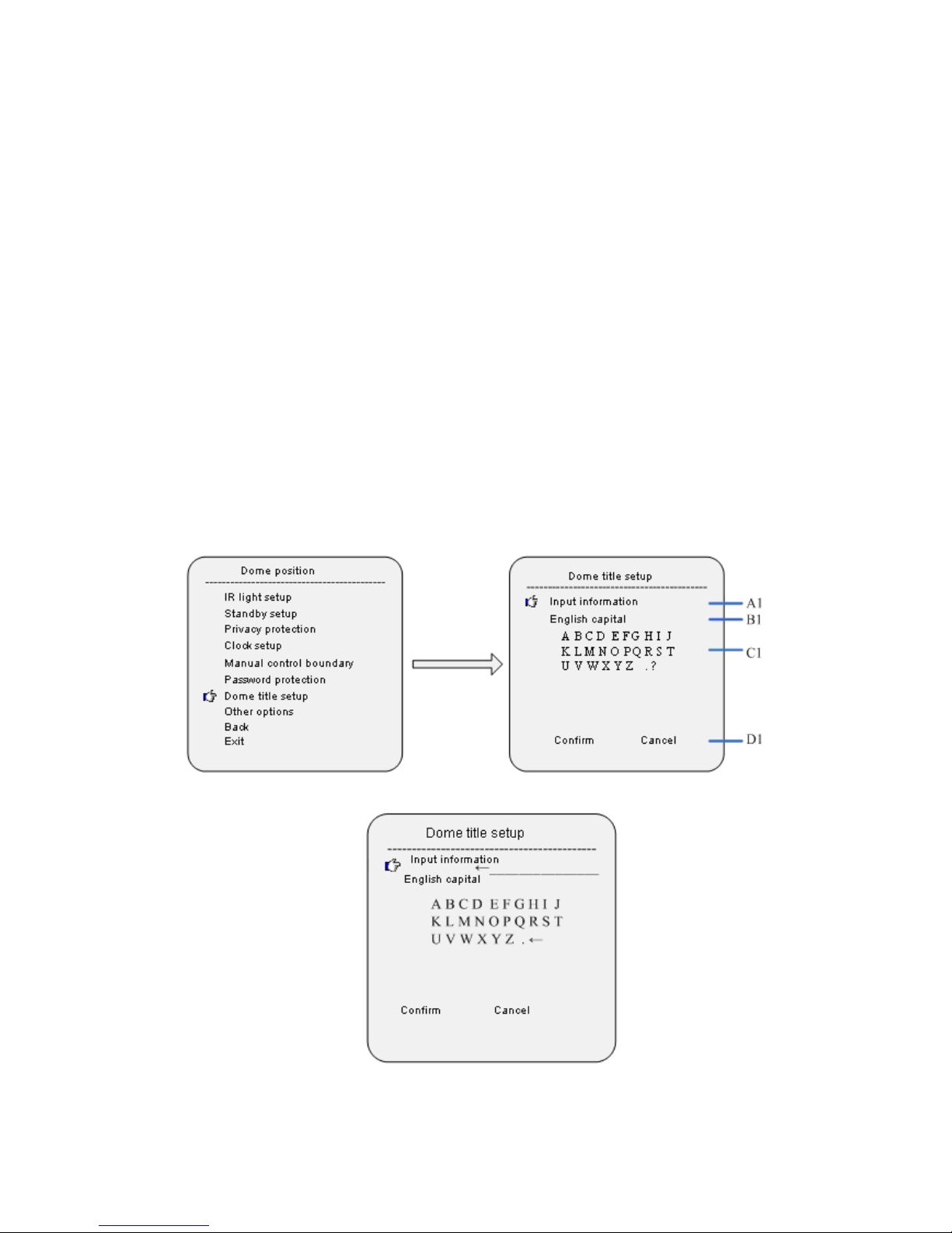
G:Dome Title Setup
25
Page 29

26
Page 30

Input method instruction:
1. Move the cursor to “input information”, and press iris open to information
edit mode. Move the joystick left and rightward to move the cursor “ ←”,
and press iris on to delete the character by the cursor and press iris off to
exit edit mode.
2. Move the cursor to input method option which is one line below “Input
Information”, and press iris on to input method setup mode. Move the
joystick upward and downward to chose the input methods, which contain
“English Capital/English lower case /Chinese/Number/Special
character/”.
3. Move the cursor to one line below input method option, and press iris on
to character input mode. Now selected character twinkles, and move the
joystick to select characters; press iris on to input the twinkling character
to the position of “←”in the “Input information” block.
H:Other Options
27
Page 31

Move the cursor to “other options”, and press iris on to its submenu.
A1:Temperature Control Mode
Move the cursor to temperature control mode, and press iris on to temperature
control setup. Use the joystick to select “Cooling/Auto/Heating/Off”, and press
iris on to confirm input.
With IR LED on, fans will be set as always on mode.
B1:Preset Freeze
In calling preset setup menu, move the cursor to “Preset Freeze”, and press iris
on to make setup. Move the joystick to set “On/Off”, and press iris on to confirm.
C1:Auto Flip
When dome rotates to 90° in vertical direction, and the user wants to
continue vertical rotation, dome will automatically rotate by 180°horizontally in
2 seconds. Press iris on to make this function as “On/off”.
D1.Auto Pause time
Auto pause time means the time period in which the dome does not receive
any pause code and after that, dome will pause automatically, and 5、15、30、60
seconds option.
E1.Menu shut time
With menu on, menu will automatically shut after a period of vacant time.
Move the cursor to “menu shut time”, and press iris on to setup mode; move the
joystick upward or downward to set time as“1 min/2 mins/5 mins/10 mins”
F1.Directi Zero Position
Move the cursor to “Direction Zero Setup”,and press iris on to direction zero
position setup mode. It shows “press iris on to confirm...”, and now you can control
dome to zero position horizontally (North),press iris on to set this position as
zero position.
28
Page 32

Camera Setup
Camera Setup
Auto Focus: auto/manual/one push/zoom trigger
Digital Zoom: off/on
BackLight Compensation: off/on
Picture Freeze: off/on
Vertical Mirror Image: off/on
Zoom Speed: low/normal/high
Day/Night: auto/day/night
Advance Option
Back
Exit
Remarks:
Auto Focus includes 4 operating modes: auto/manual/one push/zoom trigger.
In auto mode, the camera is running under auto focus condition, it is
recommended to use this mode for normal use. In manual m o de , auto focus
condition will be disable, the image would be breezing if changing scenes. If the
camera have to adjust the focus frequently in some special scenes that may cause
breezing on the image, it is recommended to use one push mode or zoom trigger
m o de . One push mode is for preliminary adjustment; zoom trigger for advanced
adjustment. Function description: when zooming, the camera will automatically
focus clearly; once zooming stopped, the camera will fix the focus. ( It is designed
some special scenes with many illuminations that will force the camera to keep
adjusting the focus and lead to unclear image)
2.Day/Nigh: Disable the function of IR Led lights activate the D/N function of the
camera for special use.
29
Page 33

A. Auto Focus
Move the cursor to “Auto Focus”,and press iris on to focus mode setup menu;
move the joystick upward and downward to select focus mode selection.
B. Digital Zoom
Move the cursor to “Digital Zoom”,and press iris on to digital zoom switch
setup. Move the joystick upward and downward to switch on/off digital zoom
C. Backlight Compensation
Switch setup: when the picture illumination is low, open backlight
compensation to higher it.
D. Picture freeze.
Move the cursor to “picture freeze”,and press iris on to picture freeze switch
setup. Move the joystick upward and downward to open or shut this function
E. Vertical Mirror Image
Move the cursor to “Vertical mirror image”,and press iris on to enter vertical
image switch setup. Move joystick upward and downward to select on/off.
F. Zoom Speed
Move the cursor to “Zoom Speed”,and press iris on to zoom speed setup
mode. Move joystick to select camera zoom speed, which can be set as“Low
speed”, “moderate speed” and “high speed”.
G:Advanced option
30
Page 34

A1. white balance mode
Move the cursor to“white balance mode”, and press iris on to enter setup
mode. Move
the joystick upward and downward as“Auto/Manual/Indoor/outdoor”.
Note:For different cameras, the setup options might be different.
B1.R Gain
Move the cursor to“R gain”,and press iris on to setup mode. Move joystick
upward and
downward to set the R gain value.
Note: Only if the white balance is set as manual, setup is available.
C1. B gain
Move the cursor to “B gain”, and press iris on to setup mode. Move the
joystick upward and downward to set B gain value.
Note: Only if white balance is set as manual, setup is available.
D1.Illumination
Move the cursor to “illumination”, and press iris on to enter setup mode.
Move the
joystick upward or downward to set illumination value.
E1.Exposure mode
Move the cursor to“exposure mode”,and press iris on to setup mode. Move
the joystick
upward and downward to select parameters, which can be set
as“Auot/Manual/Sutter priority/iris priority/Illumination priority”.
Note:For different cameras, the mode options might be different.
F1.Shutter Speed
Move the cursor to “Shutter speed”, and press iris on to enter setup mode.
Move joystick upward and downward to set shutter speed value.
G1.Wide Dynamic
Move the cursor to “wide dynamic”, and press iris on to enter setup mode.
31
Page 35

Move joystick
upward and downward to select parameters as“Low/Moderate/high”.
Note: For cameras without wide dynamic function, this option setup is not
available.
H1. Initiation Setu p
Move joystick to“initiation setup”,and press iris on to recover camera
parameters as default.
Operation Setup
A: Preset
A1. Preset Position Number
Move joystick to“preset position number”, and press iris on to setup mode.
Move joystick
upward and downward to set number. This dome supports 220 preset
positions,1-64,100-255.
32
Page 36

B1. Title Setup
Move cursor to“title setup”, and press iris on to setup submenu to make
preset position
title setup.
C1.Call
Move cursor to“call”, and press iris on to call related preset position.
D1.Setup
Press iris on to preset position setup mode, and it shows ”Press iris on to
confirm…”. User can make operation to dome, and press iris on to save current
position.
E1.Delete
Move cursor to“delete”, and press iris on to related preset position.
B:Auto Scan
A1.Scan Number
Move the cursor to“scan number”,and press iris on to setup mode. Move
joystick upward
and downward to set scan number. This dome supports 8 auto scans.
B1. Title Setup
Move cursor to “Title Setup”,and press iris on to enter scan title setup
submenu to set the
title.
C1.Start Scan
33
Page 37

Move cursor to“start scan”,and press iris on to start related scan.
D1.Left Boundary Setup
Move cursor to “Set left boundary”,and press iris on to setup mode, it
shows ”press iris on to confirm…”. User can make operate dome to expected
position, and press iris on to save current position as left boundary.
E1. Right boundary setup
Move the cursor to “set right boundary”, and press iris on to enter setup
mode,it shows ”press iris on to confirm…”. User can make operate dome to
expected position, and press iris on to save current position as right boundary.
F1.Scan speed
Move cursor to “scan speed”,and press iris on to enter setup mode. Move the
joystick
upward and downward to set the speed level as 1-30.
C:Sequence
A1.SEQ NO.
Move the cursor to SEQ NO. and press the key IRIS ON(key on control keyboard)
to enter the edition mode of sequence No., move the joystick upward and
downward to select number. Then press IRIS ON to confirm.
B1. TITLE
Move the cursor to TITLE and press IRIS ON to enter the edition mode of
sequence title.
34
Page 38

C1.START
MOVE the cursor to START and press IRIS ON to start the current sequence.
D1.<SEQUENCE SET>
Press IRIS ON to enter into the sequence setting
Move the cursor to EDIT and press IRIS ON to enter edition mode. Move the
joystick rightward and leftward to select item.
a. When the < > is on the item NO., move joystick upward and downward to select
the NO.of the preset in a sequence. There are up to 32 presets in a single
sequence.
b. When the < > is on the item PRESET, move the joystick upward and downward
to select the preset NO. you want to add in the sequence.
c.When the < > is on the item INS, move the joystick upward and downward to
select edition mode as “insert”, “ok” and “delete”.
d. Press IRIS OFF to quit the edition.
E1. Delete
Move cursor to“delete”,press Iris On to delete related sequence.
35
Page 39

D. PATTERN
A1. PATTERN NO.
Move the cursor to PATT and press the key IRIS ON(key on control keyboard) to
enter the edition mode of sequence No., move the joystick upward and downward
to select number. Then press IRIS ON to confirm.
B1. TITLE
Move the cursor to TITLE and press IRIS ON to enter the edition mode of
sequence title.
C1.START
MOVE the cursor to START and press IRIS ON to start the current Pattern.
D1. <SET>
Move the cursor to SET and press IRIS ON the enter pattern setting mode. Then
the sentence “PRESS IRIS ON TO CONFIRM”will appear on the screen. Move the
joystick to do PTZ move and press IRIS ON to confirm.
E1.DELETE
Move the cursor to DELETE and press IRIS ON to delete the current pattern.
36
Page 40

E.<ZONES>
A1.ZONE INFORMATION
B1.ZONE NO.
Move the cursor to ZONE NO. and press the key IRIS ON(key on control keyboard)
to enter the edition mode of zone No., move the joystick upward and downward to
select number. Then press IRIS ON to confirm.
C1. TITLE
Move the cursor to TITLE and press IRIS ON to enter the edition mode of zone
title.
D1.<LEFT LIMIT>
Move the cursor to <LEFT LIMIT> and press IRIS ON to start setting the left limit
of the current zone. Then the sentence “PRESS IRIS ON TO CONFIRM” will appear
on the screen. Move the joystick and press IRIS ON to confirm.
E1. <RIGHT LIMIT>
Move the cursor to <RIGHT LIMIT> and press IRIS ON to start setting the right
limit of the current zone. Then the sentence “PRESS IRIS ON TO CONFIRM” will
appear on the screen. Move the joystick and press IRIS ON to confirm.
F1.DELETE
Press IRIS ON to delete the current zone.
37
Page 41

F.TIMING ACTION
TIMING ACTION:The user could set up the required functions during the
designated time periods. These functions include presets, cruising track,pattern
tours and scanning.
Mover the cursor to the time duration to be set, and press “ Iris Open” to
enter the setting mode. Move the joystick (Left/ Right? to choose the option of
exact time of Start, Stop and Motion. Move the joystick (Up/Down) to edit the
content and the press “ Iris On” to confirm the operation.
A1. SCHEDULE NO.
The schedule of the timing action covers 7 days 1 week and 8 time periods 1 day.
B1.START
C1.STOP
D1.MOTION
Timing action modes: PRESET 1-8, SCAN 1-4, SEQUENCE 1-4, PATTERN 1-4
E1:ON/OFF
Press IRIS ON to enable or disable the timing action
F1:COPY
User can copy a schedule to other 6 days in a week.
38
Page 42
G1. BACK
Go back to upper menu
Note:
The settings of each time periods can not overlaid, and the time period can not
be allowed to exceed 00:00
If the use tries to control the dome during the TIMING ACTION, then the
operation
will be stopped and if there is no operation after 25 seconds, then the dome will
resume the timing action.
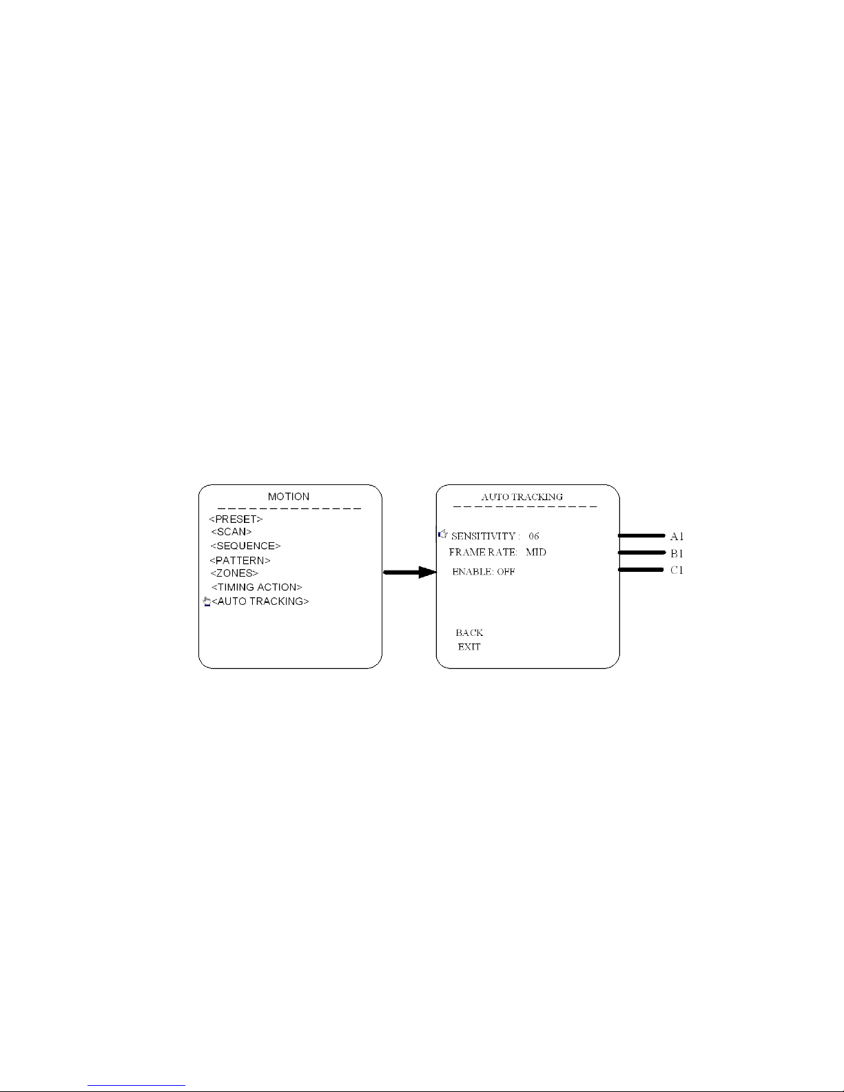
G:AUTO TRACKING
A1.SENSITIVITY
Move the cursor to the option of SENSITIVITY and mover the joystick up and
down to adjust the sensitivities. Sensitivity of auto tracking funtion. Scale from1
to 15. The smaller the value is, the higher the sensitivity is.
B1.FRAME RATE
Setting of the frame inspection rate (LOW/MID/HIGH).
39
Page 43

C1. ENABLE
Enabel or disable the auto tracking function.
*Notice: The auto tracking function is only for the speed dome with the camera
module which supports auto tracking.
RESTART
Press “Iris Open” to restart the dome.
FAC TORY DEFAULTS
Press “Iris Open” to resume all the setting to factory default settings
40
Page 44

HELP
Press “Iris Open” to check all the HELP information about the menu settings.
41
 Loading...