

Optiview HDVR4/8/16-Q2, HDVR8/161080-Q2, HDVR32-Q4, HDVR32-Q8, HDVR161080-Q8 User Manual
...Page 1

Page 2

i
Table of Contents
1
FEATURES AND SPECIFICATIONS ..................................................... 1
1.1
Overview .................................................................................................................. 1
1.2
Features ................................................................................................................... 1
1.3
Specifications ........................................................................................................... 2
1.3.42
1.3.43
1.3.44
1.3.45
1.3.46
1.3.47
1.3.48
4 Megapixel Tribrid Series .................................................................................. 98
HDVR4/8/16-Q2 ................................................................................................ 126
HDVR8/161080-Q2 ........................................................................................... 133
HDVR32-Q4 ...................................................................................................... 136
HDVR161080-Q4 .............................................................................................. 138
HDVR32-Q8 ...................................................................................................... 140
HDVR161080-Q8 .............................................................................................. 142
Page 3

ii
2
OVERVIEW AND CONTROLS ........................................................... 145
2.1
Front Panel ............................................................................................................ 145
2.1.1
2.1.2
2.1.3
2.2
2.2.30
2.2.31
2.2.32
2.2.33
2.3 Connection Sample ............................................................................................... 228
2.3.1
2.3.2
2.3.3
2.4 Remote Control ..................................................................................................... 235
2.5 Mouse Control ....................................................................................................... 237
1U Series ............................................................................................................... 150
1.5U Series ............................................................................................................ 151
2U Series ............................................................................................................... 153
Rear Panel ............................................................................................................ 155
1U Series……………………………………………………………………… 202
General 4MP 1U Series .................................................................................... 214
1.5U Series ....................................................................................................... 215
2U Series .......................................................................................................... 223
1U Series ............................................................................................................... 232
1.5U Series ............................................................................................................ 233
2U Series ............................................................................................................... 234
2.6 Virtual Keyboard & Front Panel .............................................................................. 239
2.6.1
2.6.2
Virtual Keyboard .................................................................................................... 239
Front Panel ............................................................................................................ 239
3 INSTALLATION AND CONNECTIONS ............................................... 240
3.1
Check Unpacked DVR ........................................................................................... 240
3.2
About Front Panel and Real Panel ......................................................................... 240
3.3
HDD Installation ..................................................................................................... 240
3.3.1
3.3.2
3.3.3
Smart Box Series .................................................................................................. 240
Smart 1U Series .................................................................................................... 241
Compact 1U and Mini 1U Series ........................................................................... 242
Page 4

iii
3.4
3.5
3.3.4
3.3.5
3.3.6
3.3.7
1U Series ............................................................................................................... 243
1.5U series ............................................................................................................ 244
2U series ............................................................................................................... 244
Rack Installation .................................................................................................... 245
Connecting Power Supply ...................................................................................... 245
Connecting Video Input and Output Devices .......................................................... 245
3.5.1
3.5.2
3.6
3.6.1
3.6.2
3.7
3.7.1
3.7.2
3.7.3
3.8 RS485 ................................................................................................................... 250
3.9 Other Interfaces ..................................................................................................... 250
Connecting Video Input ......................................................................................... 245
Connecting Video Output ...................................................................................... 246
Connecting Audio Input & Output, Bidirectional Audio ............................................ 246
Audio Input ............................................................................................................ 246
Audio Output ......................................................................................................... 246
Alarm Input and Output Connection ....................................................................... 247
Alarm Input and Output Details ............................................................................. 247
Alarm Input Port .................................................................................................... 248
Alarm Output Port ................................................................................................. 249
4 OVERVIEW OF NAVIGATION AND CONTROLS ............................... 251
4.1
Boot up and Shutdown ........................................................................................... 251
4.1.1
4.1.2
4.1.3
4.1.4
4.2
4.2.1
4.2.2
4.3
4.4
Boot up .................................................................................................................. 251
Shutdown .............................................................................................................. 251
Auto Resume after Power Failure ......................................................................... 251
Replace Button Battery ......................................................................................... 251
Set/Reset Password .............................................................................................. 251
Set Password ........................................................................................................ 252
Reset Password .................................................................................................... 253
Startup Wizard ....................................................................................................... 253
Live Viewing .......................................................................................................... 259
Page 5

iv
4.5
Right-Click Menu ................................................................................................... 261
4.5.1
4.5.2
4.5.3
4.5.4
4.5.5
4.5.6
4.5.7
4.5.8
4.5.9
4.5.10
4.5.11
4.5.12
4.5.13
4.6
4.6.1
4.6.2
4.6.3
4.6.4
4.6.5
4.6.6
4.6.7 PTZ ........................................................................................................................ 272
4.6.8
4.6.9
4.6.10
4.6.11
4.6.12
4.6.13
4.6.14
4.6.15
Window Switch ...................................................................................................... 262
Previous Screen/Next Screen ............................................................................... 263
PTZ Control ........................................................................................................... 263
Auto Focus ............................................................................................................ 268
Color ...................................................................................................................... 268
Display ................................................................................................................... 270
Face Search .......................................................................................................... 271
Search ................................................................................................................... 271
Record Control ...................................................................................................... 271
Alarm Output ..................................................................................................... 271
Remote Device ................................................................................................. 271
Video Matrix ...................................................................................................... 271
Main menu ........................................................................................................ 271
Navigation Bar ....................................................................................................... 271
Main Menu ............................................................................................................. 272
Output Screen ....................................................................................................... 272
Previous/Next Screen............................................................................................ 272
Tour ....................................................................................................................... 272
Favorites ................................................................................................................ 272
Channel ................................................................................................................. 272
Color ...................................................................................................................... 272
Search ................................................................................................................... 272
Alarm Status ..................................................................................................... 272
Channel Info ...................................................................................................... 273
Remote Device ................................................................................................. 273
Network ............................................................................................................. 273
HDD Manager ................................................................................................... 273
USB Manager ................................................................................................... 273
4.7 USB Device Auto Pop-up ....................................................................................... 274
4.8 Main Menu ............................................................................................................. 274
4.9 Operation............................................................................................................... 275
4.9.1
4.9.2
4.9.3
4.9.4
Search ................................................................................................................... 275
Human Face Search ............................................................................................. 284
Backup .................................................................................................................. 285
Shut Down ............................................................................................................. 287
Page 6

v
4.10 Information ............................................................................................................ 288
4.10.1
4.10.2
4.10.3
4.10.4 Log .................................................................................................................... 298
4.11 Setting ................................................................................................................... 300
4.11.1
4.11.2
4.11.3
4.11.4
4.11.5
System Info ....................................................................................................... 288
Event ................................................................................................................. 295
Network ............................................................................................................. 295
Camera ............................................................................................................. 300
Network ............................................................................................................. 318
Event ................................................................................................................. 338
Storage ............................................................................................................. 370
System .............................................................................................................. 383
5 WEB OPERATION ............................................................................. 409
5.1
Network Connection .............................................................................................. 409
5.2
Login ..................................................................................................................... 409
5.3
LAN Mode ............................................................................................................. 411
5.4
Real-time Monitor .................................................................................................. 413
5.4.1 Fisheye de-warp .................................................................................................... 414
5.5 PTZ ....................................................................................................................... 416
5.6
Image/Relay-out .................................................................................................... 417
5.7
5.6.1
5.6.2
Image .................................................................................................................... 417
Relay output .......................................................................................................... 417
WAN Login ............................................................................................................ 418
5.8
Setup ..................................................................................................................... 419
5.8.1
5.8.2
5.8.3
5.8.4
Camera .................................................................................................................. 419
Network ................................................................................................................. 429
Event ..................................................................................................................... 445
Storage .................................................................................................................. 467
Page 7

ix
5.9
5.8.5
Setting ................................................................................................................... 471
Information ............................................................................................................ 489
5.9.1
5.9.2 Log ........................................................................................................................ 490
5.9.3 Online User ........................................................................................................... 491
5.9.4 HDD ....................................................................................................................... 491
5.10
5.10.1
5.10.2
5.10.3
5.10.4
5.10.5
5.11
5.12
5.13
Version .................................................................................................................. 489
Playback ................................................................................................................ 491
Search Record .................................................................................................. 492
File List .............................................................................................................. 493
Playback ........................................................................................................... 494
Download .......................................................................................................... 494
Load more ......................................................................................................... 495
Face Search .......................................................................................................... 497
Alarm ..................................................................................................................... 498
Log out .................................................................................................................. 499
5.14
Un-install Web Control ........................................................................................... 500
6 PROFESSIONAL SURVEILLANCE SYSTEM ..................................... 501
7 FAQ ................................................................................................... 502
APPENDIX A HDD CAPACITY CALCULATION ...................................... 510
APPENDIX B COMPATIBLE BACKUP DEVICES ..................................... 512
Appendix B-1 Compatible USB list ................................................................................... 512
Appendix B-2 Compatible SD Card list ............................................................................ 513
Page 8

x
Appendix B-3 Compatible Portable HDD list .................................................................... 513
Appendix B-4 Compatible USB DVD List ......................................................................... 513
Appendix B-5 Compatible SATA DVD List ........................................................................ 513
Appendix B-6 Compatible SATA HDD List ....................................................................... 514
APPENDIX C COMPATIBLE CD/DVD BURNER LIST ............................ 518
APPENDIX D COMPATIBLE DISPLAYER LIST ...................................... 519
APPENDIX E COMPATIBLE SWITCHER ................................................. 520
APPENDIX F COMPATIBLE WIRELESS MOUSE LIST .......................... 521
APPENDIX G EARTHING ....................................................................... 522
Page 9

xi
Welcome
Thank you for purchasing our 5-WAY DVR!
This user’s manual is designed to be a reference tool for the installation and operation of
your system.
Here you can find information about this series standalone DVR features and functions, as
well as a detailed menu tree.
Before installation and operation please read the following safeguards and warnings
carefully!
Page 10

xii
Important Safeguards and Warnings
1.Electrical safety
All installation and operation here should conform to your local electrical safety codes.
The product must be grounded to reduce the risk of electric shock.
We assume no liability or responsibility for all the fires or electrical shock caused by
improper handling or installation.
2.Transportation security
Heavy stress, violent vibration or water splash are not allowed during transportation,
storage and installation.
3.Installation
Keep upwards. Handle with care.
Do not apply power to the DVR before completing installation.
Do not place objects on the DVR.
4.Qualified engineers needed
All the examination and repair work should be done by the qualified service engineers.
We are not liable for any problems caused by unauthorized modifications or attempted
repair.
5.Environment
The DVR should be installed in a cool, dry place away from direct sunlight, inflammable,
explosive substances and etc.
6. Accessories
Be sure to use all the accessories recommended by manufacturer.
Before installation, please open the package and check all the components are included.
Contact your local retailer ASAP if something is broken in your package.
7. Lithium battery
Improper battery use may result in fire, explosion, or personal injury!
When replace the battery, please make sure you are using the same model!
RISK OF EXPLOSION IF BATTERY IS REPLACED BY AN INCORRECT TYPE.
DISPOSE OF USED BATTERIES ACCORDING TO THE INSTRUCTIONS.
CAUTION
FOR YOUR OWN SAFETY, PLEASE CHANGE SYSTEM DEFAULT PASSWORD
AFTER YOU FIRST LOGIN!
Page 11

1
1 FEATURES AND SPECIFICATIONS
1.1 Overview
The standalone series DVR is an excellent digital monitor product designed for security
field.
It adopts embedded Linux OS to maintain reliable operation. Popular H.264 compression
algorithm and G.711 audio compression technology realize high quality, low bit stream.
Unique frame by frame play function is suitable for detailed analysis. It has various
functions such as record, playback, monitor at the same time and can guarantee audio
video synchronization. This series product has advanced technology and strong network
data transmission function.
This series device adopts embedded design to achieve high security and reliability. It can
work in the local end, and at the same time, when connecting it to the professional
surveillance software (PSS), it can connect to the security network to realize strong
network and remote monitor function.
This series product can be widely used in various areas such as banking,
telecommunication, electric power, interrogation, transportation, intelligent resident zone,
factory, warehouse, resources, and water conservancy.
1.2 Features
This series product has the following features:
Real-time surveillance
Support VGA port and HDMI port. Realize the surveillance through displayer. Support
HDMI, VGA, and TV output at the same time.
Storage function
Special data format to guarantee data security and can remove the risk of the vicious data
modification. Support digital watermark.
Compression format
Support multiple-channel audio and video. An independent hardware decodes the audio
and video signal from each channel to maintain video and audio synchronization.
Backup function
Support backup operation via USB port (such as U disk, portable HDD, burner)
Client-end user can download the file to local HDD to backup via network.
Record & playback function
Page 12

2
Support each channel real-time record independently, and at the same time it can support
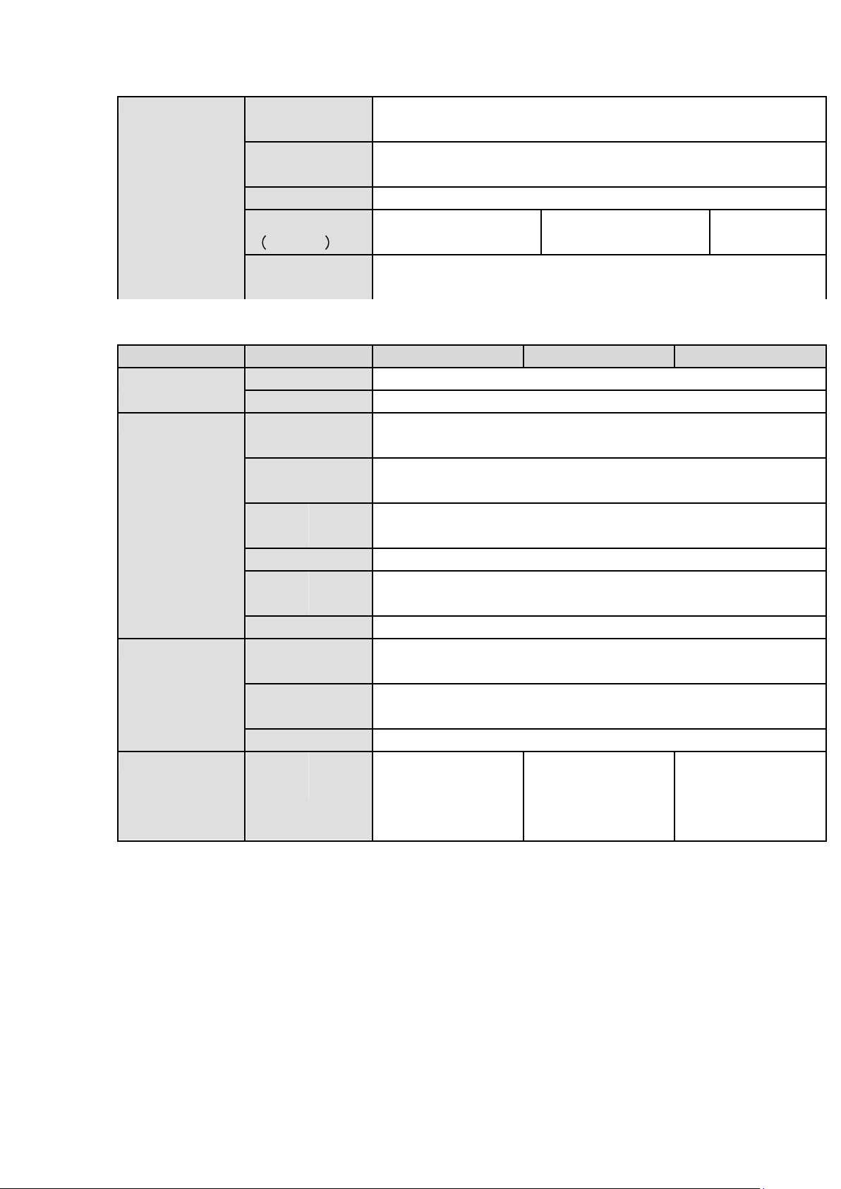
Model
Parameters
4-ch
8-ch
16-ch
System
Main Processor
Industrial embedded micro controller
OS
Embedded LINUX
Video
Parameters
Video Encode
Standard
H.264+/H.264
Encode
Resolution
Main stream:
2K(2560*1440)/1080P/720P/960H/D1/HD1/BCIF/CIF/QCIF
Sub stream: D1/CIF/QCIF
Video Frame Rate
2K resolution: PAL:1~15f/s;NTSC:1~15f/s
Other resolutions: PAL:1~25f/s;NTSC:1~30f/s
search, forward play, network monitor, record search, download and etc.
Support various playback modes: slow play, fast play, backward play and frame by frame play.
Support time title overlay so that you can view event accurate occurred time
Support customized zoom function during the preview.
Network operation
Support network remote real-time monitor, remote record search and remote PTZ control.
Alarm activation function
Several relay alarm outputs to realize alarm activation and on-site light control.
The alarm input port and output has the protection circuit to guarantee device safety.
Communication port
RS485 port can realize alarm input and PTZ control.
RS232 port can connect to keyboard to realize central control, and can also connect to PC COM
to upgrade system and realize maintenance, and matrix control.
Standard Ethernet port can realize network access function.
The dual-network port has the multiple-access, fault-tolerance, load-balance setup mode.
PTZ control
Support PTZ decoder via RS485.
Intelligent operation
Mouse operation function
In the menu, support copy and paste setup function
UPNP (Universal Plug and Play)
Establish mapping connection between LAN and WAN via UPNP protocol.
Slight function differences may be found due to different series.
1.3 Specifications
1.3.1
General 4MP 1U Series
Page 13

3
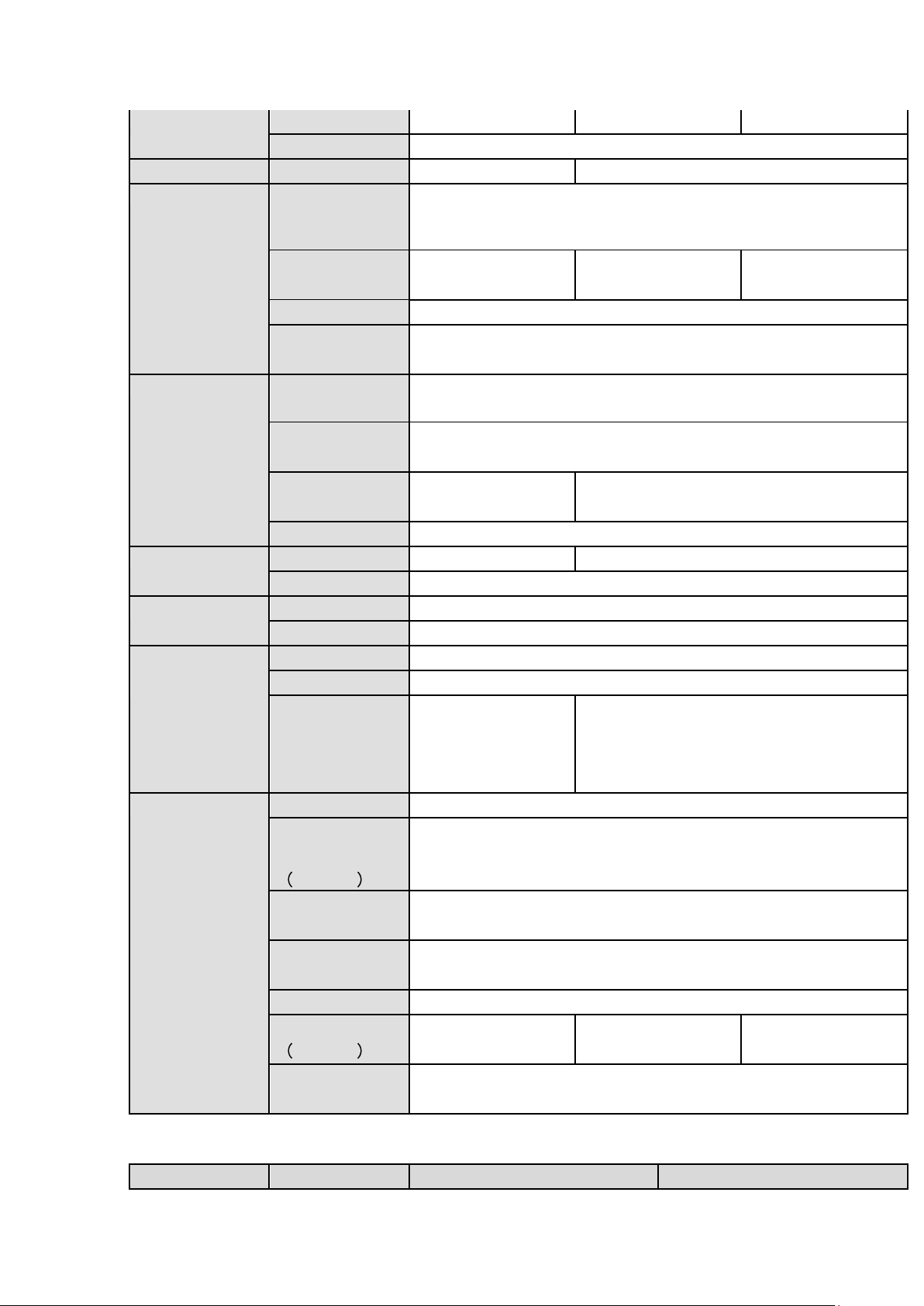
Video Frame Rate
32Kbps-6144Kbps,
For 720P: default setup is 2Mbps,max supports 4Mbps.
For 1080N: default setup is 4Mbps,max supports 6Mbps.
For 2K: non realtime default setup is 4Mbps,max supports 6Mbps.
Bit Stream Type
Video stream/composite stream
Dual-Stream
Support
Audio
Parameters
Encode Standard
G.711A/G.711U/PCM
Audio Sampling
Rate
8KHz,16Bit
Audio Bit Rate
64Kbps
Video Port
Analog Video
Input
4-ch BNC port
(5-WAY /CVBS)
8-ch BNC port
(5-WAY /CVBS)
16-ch BNC port
(5-WAY /CVBS)
Network Video
Input
Max add 2 IP
channel
connection.
Analog
/digital channel
switch. Max 6 IP
channel
connections
Connection
Max add 4 IP
channel
connection.
Analog
/digital channel
switch. Max 12
IP channel
connections
Connection
Max add 8 IP
channel
connection.
Analog
/digital channel
switch. Max 24 IP
channel
connections
Connection
Page 14

4
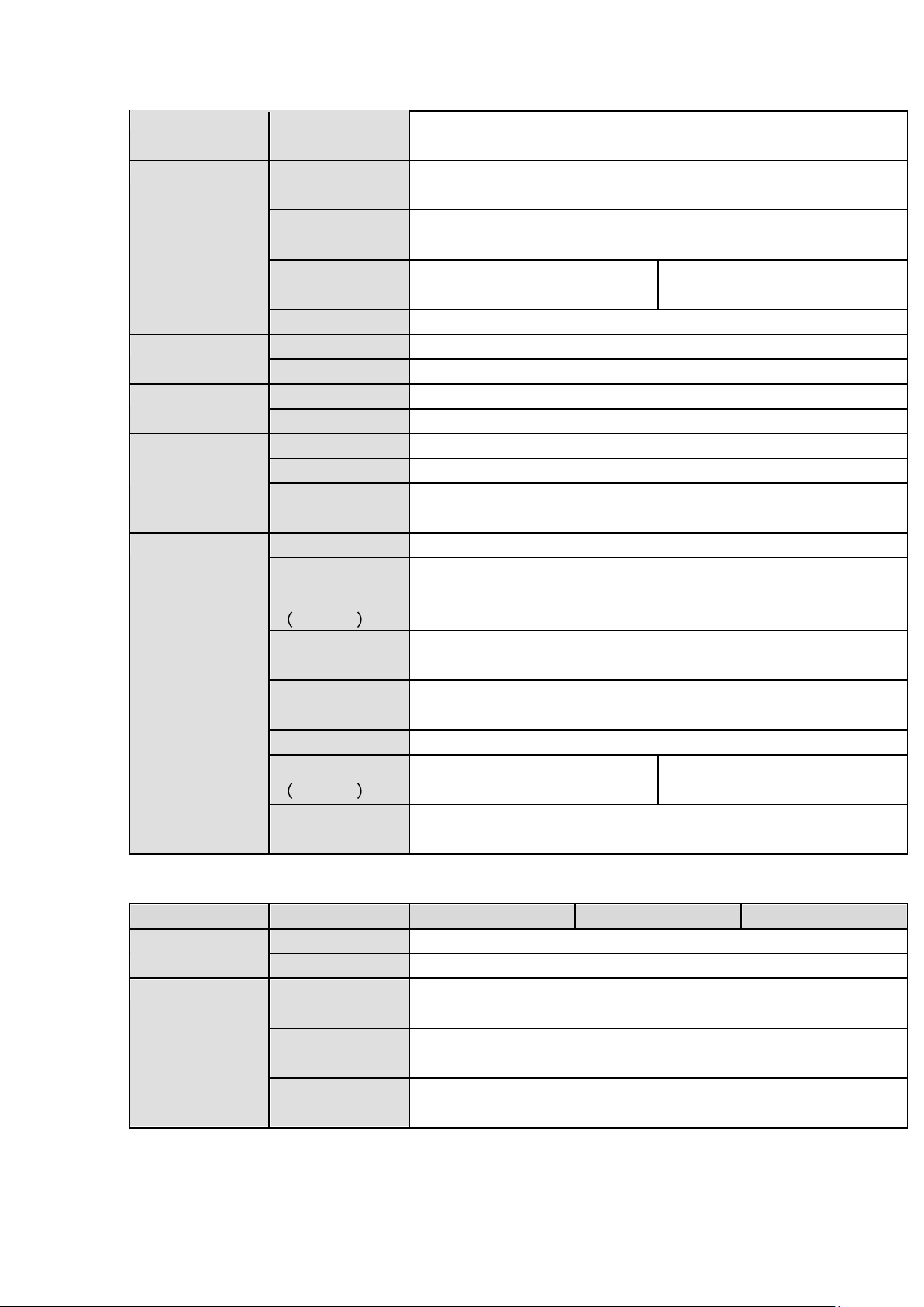
Model
Parameters
4-ch
8-ch
16-ch
bandwidth:8Mbp
s-24Mbps
bandwidth:16
Mbps-48Mbps
bandwidth:32Mbps-
96Mbps
Video Output
1-channel VGA output,
1-channel HDMI output, max 4K(3840*2160)@30f
HDMI/ VGA video output at the same time (of the same video source
or different video source).
Loop Output
N/A
Matrix Output
When the HDMI and VGA are outputting different video, system
supports one matrix output.
Audio Port
Audio Input
1-channel RCA port.
Coaxial Audio
Input
N/A
Audio Output
1-channel RCA port.
Bidirectional Talk
Input
Reuse the audio input/output port
Record
Record Mode
Schedule record/manual record/MD record/Alarm record/intelligent
record
Playback Mode
Instant playback, normal playback, event playback, mark playback,
smart playback
Playback Channel
4-channel
8-channel
16-channel
Backup Mode
HDD, burner, USB device, network backup
Alarm
Alarm Input
N/A
Alarm Output
N/A
HDD
HDD Port
2 SATA ports
One HDD Space
8T
Communication
Port
Network
1 RJ45 port, 1000Mbps Ethernet port
Communication
1 RS485 port
USB
2 USB ports(One USB2.0 port at the front panel and one USB3.0 port
at the rear panel)
Others
Power
DC12V
Power
Consumption (No
HDD)
≤12W
≤13W
≤20W
Working
Temperature
-10℃-+55℃
Working Humidity
10%~90%
Dimensions
1U case, 375mm(W)×280mm(D)×50mm(H)
Weight No HDD
≤1.60KG
≤1.60KG
≤1.75KG
Installation Mode
Desk
Page 15

5
1.3.2
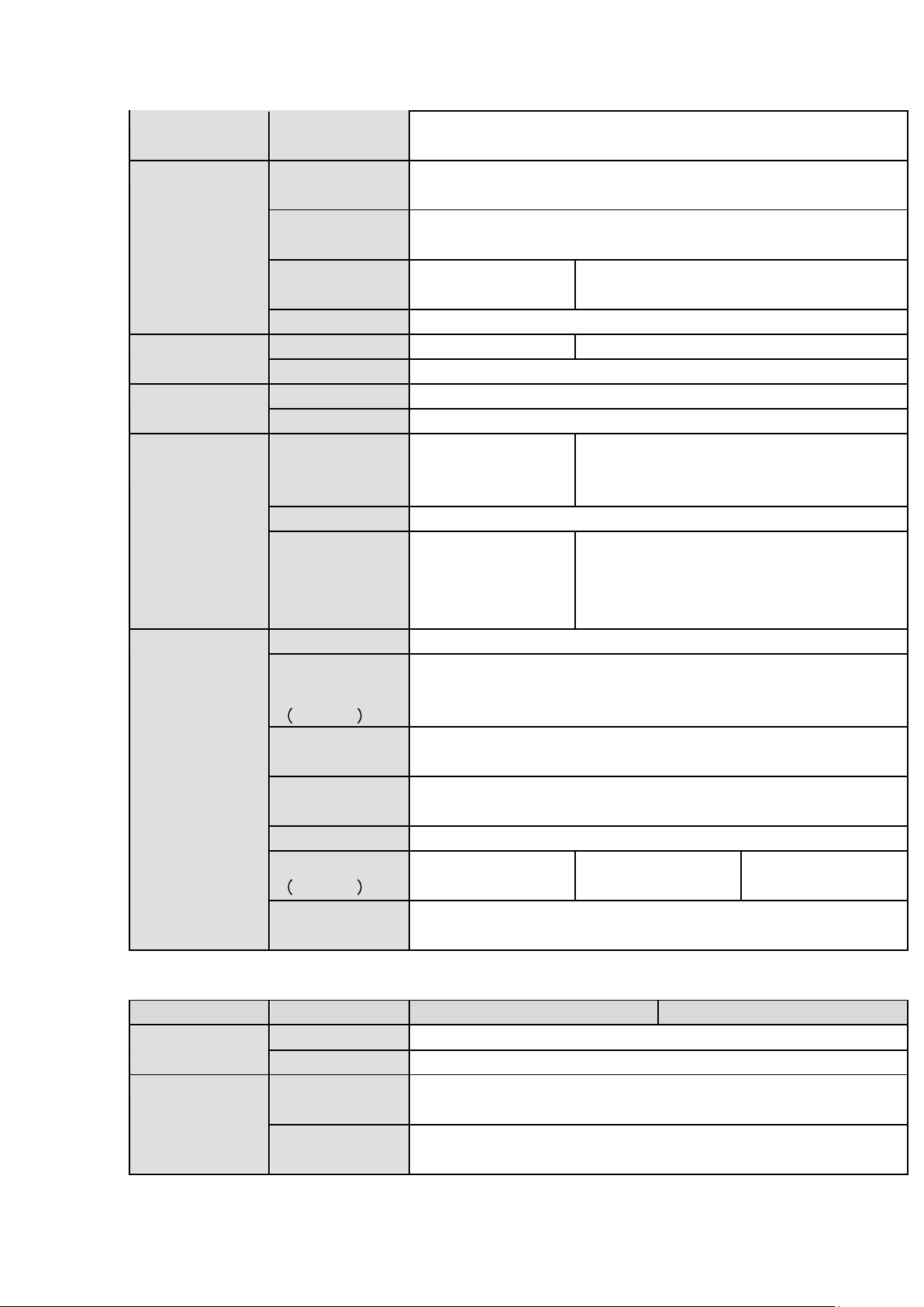
Model
Parameters
4-Ch
8-Ch
16-Ch
System
Main Processor
High-performance industrial embedded micro controller
OS
Embedded LINUX
Video
Video Encode
Standard
H.264
Encode
Resolution
1080P@15f/1080N/720P/960H/D1/HD1/2CIF/CIF
Video
Rate
Frame
PAL:1~25f/s;NTSC:1~30f/s
Video Bit Rate
32Kbps~6144Kbps
Bit
Type
Stream
Video stream/composite stream
Dual-Stream
Support
Audio
Encode
Standard
G.711A, G.711U, PCM
Audio
Sampling Rate
8KHz,16Bit
Audio Bit Rate
64Kbps
Video Port
Analog
Input
Video
4-ch BNC port
(CVBS/CVI/AHD /other
analog HD video selfadaptive)
8-ch BNC
port(CVBS/CVI/AHD
/other analog HD video
self-adaptive)
16-ch BNC
port(CVBS/CVI
/AHD /other
analog HD
video
self-adaptive)
HDVR4/8/16-Q2
Page 16

6
Network Video
Input
There is no IP
channel by default.
Max add 2 IP
channel
connections
Analog
/digital channel
switch. Max 6 IP
channel
connections
Connection
bandwidth:0Mbps24Mbps
There is no IP
channel by default.
Max add 4 IP
channel
connections
Analog
/digital channel
switch. Max 12 IP
channel
connections
Connection
bandwidth:0Mbps48Mbps
There is
no IP
channel
by default.
Max add 8
IP channel
connectio
ns
Analog
/digital
channel
switch.
Max 24 IP
channel
connectio
ns
Connectio
n
bandwidth
:0Mbps-96
Mbps
Page 17

7
Video Output
1-ch VGA output,
1-ch HDMI output,
HDMI/ VGA video output at the same time (VGA/HDMI of the same
video source)
Loop Output
N/A
Matrix Output
N/A
VGA/HDMI
optional
Audio Port
External
Audio Input
4-ch,RCA port,
Coaxial Audio
Input
N/A
Audio Output
1-ch RCA port
Bidirectional
Talk Input
Support(Reuse the audio port of the 1
st
channel)
Record
Record Mode
Auto record, manual record, motion detect record, alarm record
Playback Mode
Instant playback, normal playback, event playback, mark playback,
smart playback
Record
Playback
Max 4-ch playback
Max 8-ch playback
Max 16-ch
playback
Backup Mode
HDD, burner, flash disk, network backup.
Alarm
Alarm Input
8-ch alarm input
8-ch alarm input
16-ch alarm
input
Alarm Output
3-ch alarm output
HDD
HDD Port
2 SATA ports. Does not support eSATA port.
Space/HDD
6T
Communicatio
n Port
Network
1 RJ45 port, 100Mbps Ethernet port
1 RJ45 port,
1000Mbps
Ethernet port
Communicatio
n
RS485 port
USB
2 USB2.0 ports(One at the front panel and one at
the rear panel)
1 USB2.0 port
and 1 USB3.0
port (One
USB2.0 port at
the front panel
and one
USB3.0 port at
the rear panel)
Other
Power
DC12V
Power
Consumption
No HDD
≤7W
≤8W
≤10W
Page 18
8
Working
Temperature
-10℃-+55℃
Working
Humidity
10%~90%
Dimension
1U case,375mm(W)×280mm(D)×50mm(H)
Weight
No HDD
≤1.5KG
≤1.65KG
≤1.8KG
Installation
Mode
Desk installation
Model
Parameters
4-Ch
8-Ch
16-Ch
System
Main Processor
High-performance industrial embedded micro controller
OS
Embedded LINUX
Video
Video Encode
Standard
H.264
Encode
Resolution
1080P/720P/960H/D1/HD1/2CIF/CIF
Video
Rate
Frame
PAL:1~25f/s;NTSC:1~30f/s
Video Bit Rate
32Kbps~6144Kbps
Bit
Type
Stream
Video stream/composite stream
Dual-Stream
Support
Audio
Encode
Standard
G.711A, G.711U, PCM
Audio
Sampling Rate
8KHz,16Bit
Audio Bit Rate
64Kbps
Video Port
Analog
Input
Video
4-ch BNC port
(CVBS/CVI/AHD
/other analog HD
video self-adaptive)
8-ch BNC
port(CVBS/CVI/AHD
/other analog HD
video self-adaptive)
16-ch BNC
port(CVBS/CVI/AHD
/other analog HD
video self-adaptive)
1.3.3
HDVR8/161080-Q2
Page 19

9
Network Video
Input
There is no IP
channel by
default. Max
add 2 IP
channel
connections.
Analog
/digital channel
switch. Max 6
IP channel
connections
Connection
bandwidth:0Mb
ps-24Mbps
There is no IP
channel by
default. Max
add 4 IP
channel
connections
Analog
/digital channel
switch. Max 12
IP channel
connections
Connection
bandwidth:0Mb
ps-48Mbps
There is no IP
channel by
default. Max
add 8 IP
channel
connections
Analog
/digital channel
switch. Max 24
IP channel
connections
Connection
bandwidth:0Mb
ps-96Mbps
Video Output
1-ch VGA output,
1-ch HDMI output,
HDMI/ VGA video output at the same time (VGA/HDMI of the same
video source)
Loop Output
N/A
Matrix Output
N/A
VGA/HDMI optional
Page 20

10
Audio Port
External
Audio Input
4-ch,RCA port,
Coaxial Audio
Input
N/A
Audio Output
1-ch RCA port
Bidirectional
Talk Input
Support(Reuse the audio port of the 1
st
channel)
Record
Record Mode
Auto record, manual record, motion detect record, alarm record
Playback Mode
Instant playback, normal playback, event playback, mark playback,
smart playback
Record
Playback
Max 4-ch playback
Max 8-ch playback
Max 16-ch playback
Backup Mode
HDD, burner, flash disk, network backup.
Alarm
Alarm Input
8-ch alarm input
8-ch alarm input
16-ch alarm input
Alarm Output
3-ch alarm output
HDD
HDD Port
2 SATA ports. Does not support eSATA port.
Space/HDD
6T
Communication
Port
Network
1 RJ45 port,
100Mbps Ethernet
port
1 RJ45 port, 1000Mbps Ethernet port
Communication
RS485 port
USB
2 USB2.0 ports(One
at the front panel
and one at the rear
panel)
1 USB2.0 port and 1 USB3.0 port (One
USB2.0 port at the front panel and one
USB3.0 port at the rear panel)
Other
Power
DC12V
Power
Consumption
No HDD
≤8W
≤10W
≤15W
Working
Temperature
-10℃-+55℃
Working
Humidity
10%~90%
Dimension
1U case,375mm(W)×280mm(D)×50mm(H)
Weight
No HDD
≤1.5KG
≤1.65KG
≤1.8KG
Installation
Mode
Desk installation
Page 21

11
1.3.4
Model
Parameters
8-Ch
16-Ch
32-Ch
System
Main Processor
High-performance industrial embedded micro controller
OS
Embedded LINUX
Video
Video Encode
Standard
H.264H, H.264, H.264B
Encode
Resolution
1080P@15fps/1080N/720P/960H/D1/HD1/2CIF/CIF
Video
Rate
Frame
PAL:1~25f/s;NTSC:1~30f/s
Video Bit Rate
32Kbps~6144Kbps
( For 720P:default value is 2Mbps,max value is 4Mbps.
For 1080P:default value is 2Mbps,max value is 6Mbps)
Bit
Type
Stream
Video stream/composite stream
Dual-Stream
Support
Audio
Encode
Standard
G.711A, G.711U, PCM
Audio
Sampling Rate
8KHz,16Bit
Audio Bit Rate
64Kbps
Video Port
Analog
Video
8-ch BNC port
16-ch BNC
32-ch BNC
Input
(5-WAY HD
port(5-WAY HD
port(5-WAY HD
video/general
video/general
video/general
standard definition
standard definition
standard definition
video self-adaptive)
video self-adaptive)
video self-adaptive)
Network Video
Input
Support 4 IP
channels by
default.
Analog
/digital channel
switch. Max 12
IP channel
connections.
Connection
bandwidth:16M
bps-48Mbps
Support 8 IP
channels by
default.
Analog
/digital channel
switch. Max 24
IP channel
connections.
Connection
bandwidth:32M
bps-96Mbps
There is no IP
channel by
default.
Analog
/digital channel
switch. Max 16
IP channel
connections.
Connection
bandwidth:0Mb
ps-64Mbps
Video Output
1-ch VGA output,
1-ch VGA output,
1-ch VGA output,
1-ch HDMI output,
2-ch HDMI output,
2-ch HDMI output,
1-ch TV output,
1-ch TV output,
1-ch TV output,
HDMI/VGA/TV video
HDMI1/VGA/TV
HDMI1/VGA/TV
output at the same
video output at the
video output at the
time
same time
same time
( HDMI/VGA/TV of
(HDMI1/VGA/TV
(HDMI1/VGA/TV
the same video
of the same video
of the same video
HDVR32-Q4
Page 22
12
source)
source)
source)
Loop Output
N/A
Matrix Output
N/A
HDMI2 port support matrix output
Audio Port
External
Audio Input
4-channel BNC port,
Coaxial Audio
Input
8-channel
16-channel
32-channel
Audio Output
1-ch BNC port
Bidirectional
Talk Input
Support(Independent bidirectional talk port)
Record
Record Mode
Card number record, mark record, alarm record, motion detection
record, regular record, manual record, intelligent record.
Playback Mode
Instant playback, normal playback, event playback, mark playback,
intelligent playback(human face, motion detection)
Record
Playback
Max 8-ch playback
Max 16-ch playback
Backup Mode
HDD, burner, flash disk, network backup.
Alarm
Alarm Input
8-channel
16-channel
Alarm Output
6-channel
HDD
HDD Port
4 SATA ports. Support eSATA port.
Space/HDD
8T
Communication
Port
Network
1 RJ45 port, 1000Mbps Ethernet port
Communication
1 RS232 port, 1 RS422 port, 1 RS485 port
USB
3 USB ports(One at
the front panel and
two at the rear
panel)
3 USB ports(One at the front panel and two
at the rear panel. The rear panel supports
USB3.0)
Other
Power
AC100-240V 1.9A 50/60Hz
Power
Consumption
No HDD
30W (No HDD)
Working
Temperature
-10℃-+55℃
Working
Humidity
10%~90%
Dimension
1.5U case,440mm(W)×410mm(D)×70mm(H)
Weight
No HDD
≤7KG (No HDD)
≤7.2KG (No HDD)
≤7.5KG (No HDD)
Installation
Mode
Desk installation
Model
Parameters
8-Ch
16-Ch
1.3.5
HDVR161080-Q4
Page 23

13
System
Main Processor
High-performance industrial embedded micro controller
OS
Embedded LINUX
Video
Video Encode
Standard
H.264H, H.264, H.264B
Encode
Resolution
1080P/720P/960H/D1/HD1/2CIF/CIF/
Video Frame
Rate
PAL:1~25f/s;NTSC:1~30f/s
Video Bit Rate
32Kbps~6144Kbps
( For 720P:default value is 2Mbps,max value is 4Mbps.
For 1080P:default value is 4Mbps,max value is 6Mbps)
Bit Stream
Type
Video stream/composite stream
Dual-Stream
Support
Audio
Encode
Standard
G.711A, G.711U, PCM
Audio
Sampling Rate
8KHz,16Bit
Audio Bit Rate
64Kbps
Video Port
Analog Video
Input
8-ch BNC port (5-WAY HD
video/general standard
definition video self-adaptive)
16-ch BNC port(5-WAY HD
video/general standard
definition video self-adaptive)
Network Video
Input
Support 4 IP channels by
default.
Analog
/digital channel
switch. Max 12 IP channel
connections.
Connection
bandwidth:16Mbps-48Mbp
s
Support 8 IP channels by
default.
Analog
/digital channel
switch. Max 24 IP channel
connections.
Connection
bandwidth:32Mbps-96Mbp
s
Video Output
1- ch VGA output,
2- ch HDMI output,
1-ch TV output,
HDMI1/VGA/TV video output at the same time (HDMI1/VGA/TV
of the same video source)
Loop Output
N/A
Matrix Output
N/A
HDMI2 port support matrix output
Audio Port
External
Audio Input
4-channel BNC port,
Coaxial Audio
Input
8-channel
16-channel
Audio Output
1-channel BNC port
Page 24
14
Bidirectional
Talk Input
Support(Independent bidirectional talk port)
Record
Record Mode
Card number record, mark record, alarm record, motion detection
record, regular record, manual record, intelligent record.
Playback Mode
Instant playback, normal playback, event playback, mark playback,
intelligent playback(human face, motion detection)
Record
Playback
Max 8-ch playback
Max 16-ch playback
Backup Mode
HDD, burner, flash disk, network backup.
Alarm
Alarm Input
16-channel
Alarm Output
6-channel
HDD
HDD Port
4 SATA ports. Support eSATA port.
Space/HDD
8T
Communication
Port
Network
1 RJ45 port, 1000Mbps Ethernet port
Communication
1 RS232 port, 1 RS422 port, 1 RS485 port
USB
3 USB ports (One at the front panel and two at the rear panel. The
rear panel supports USB3.0)
Other
Power
AC100-240V 1.9A 50/60Hz
Power
Consumption
No HDD
30W (No HDD)
Working
Temperature
-10℃-+55℃
Working
Humidity
10%~90%
Dimension
1.5U case,440mm(W)×410mm(D)×70mm(H)
Weight
No HDD
≤7KG (No HDD)
≤7.2KG (No HDD)
Installation
Mode
Desk installation
Model
Parameters
8-Ch
16-Ch
32-Ch
System
Main Processor
High-performance industrial embedded micro controller
OS
Embedded LINUX
Video
Video Encode
Standard
H.264H, H.264, H.264B
Encode
Resolution
1080P@15fps/1080N/720P/960H/D1/HD1/2CIF/CIF
Video Frame
Rate
PAL:1~25f/s;NTSC:1~30f/s
1.3.6
HDVR32-Q8
Page 25

15
Video Bit Rate
32Kbps~6144Kbps
( For 720P:default value is 2Mbps,max value is 4Mbps.
For 1080P:default value is 2Mbps,max value is 6Mbps)
Bit Stream
Type
Video stream/composite stream
Dual-Stream
Support
Audio
Encode
Standard
G.711A, G.711U, PCM
Audio
Sampling Rate
8KHz,16Bit
Audio Bit Rate
64Kbps
Video Port
Analog Video
8-ch BNC port
16-ch BNC
32-ch BNC
Input
(5-WAY HD
port(5-WAY HD
port(5-WAY HD
video/general
video/general
video/general
standard definition
standard definition
standard definition
video self-adaptive)
video self-adaptive)
video self-adaptive)
Network Video
Input
Support 4 IP
channels by
default.
Analog
/digital channel
switch. Max 12
IP channel
connections.
Connection
bandwidth:16M
bps-48Mbps
Support 8 IP
channels by
default.
Analog
/digital channel
switch. Max 24
IP channel
connections.
Connection
bandwidth:32M
bps-96Mbps
There is no IP
channel by
default.
Analog
/digital channel
switch. Max 16
IP channel
connections.
Connection
bandwidth:0Mb
ps-64Mbps
Video Output
1-ch VGA output,
1-ch VGA output,
1-ch VGA output,
1-ch HDMI output,
2-ch HDMI output,
2-ch HDMI output,
1-ch TV output,
1-ch TV output,
1-ch TV output,
HDMI/VGA/TV video
HDMI1/VGA/TV
HDMI1/VGA/TV
output at the same
video output at the
video output at the
time
same time
same time
( HDMI/VGA/TV of
(HDMI1/VGA/TV
(HDMI1/VGA/TV
the same video
of the same video
of the same video
source)
source)
source)
Loop Output
N/A
Matrix Output
N/A
HDMI2 port support matrix output
Audio Port
External
Audio Input
8-channel BNC port,
Coaxial Audio
Input
8-channel
16-channel
32-channel
Audio Output
1-ch BNC port
Page 26
16
Bidirectional
Talk Input
Support(Independent bidirectional talk port)
Record
Record Mode
Card number record, mark record, alarm record, motion detection
record, regular record, manual record, intelligent record.
Playback Mode
Instant playback, normal playback, event playback, mark playback,
intelligent playback(human face, motion detection)
Record
Playback
Max 8-ch playback
Max 16-ch playback
Backup Mode
HDD, burner, flash disk, network backup.
Alarm
Alarm Input
8-channel
16-channel
Alarm Output
6-channel
HDD
HDD Port
8 SATA ports. Support eSATA port.
Space/HDD
8T
Communication
Port
Network
1 RJ45 port,
1000Mbps Ethernet
port
2 RJ45 ports, 1000Mbps Ethernet port
Communication
1 RS232 port, 1 RS422 port, 1 RS485 port
USB
4 USB ports(Two at
the front panel and
two at the rear
panel)
4 USB ports(Two at the front panel and two
at the rear panel. The rear panel supports
USB3.0)
Other
Power
AC100-240V 1.9A 50/60Hz
Power
Consumption
No HDD
35W (No HDD)
Working
Temperature
-10℃-+55℃
Working
Humidity
10%~90%
Dimension
2U case,440mm(W)×460mm(D)×89mm(H)
Weight
No HDD
≤9KG (No HDD)
≤9.2KG (No HDD)
≤9.4KG (No HDD)
Installation
Mode
Desk installation
Model
Parameters
8-Ch
16-Ch
System
Main Processor
High-performance industrial embedded micro controller
OS
Embedded LINUX
Video
Video Encode
Standard
H.264H, H.264, H.264B
Encode
Resolution
1080P/720P/960H/D1/HD1/2CIF/CIF/
1.3.7
HDVR161080-Q8
Page 27

17
Video Frame
Rate
PAL:1~25f/s;NTSC:1~30f/s
Video Bit Rate
32Kbps~6144Kbps
( For 720P:default value is 2Mbps,max value is 4Mbps.
For 1080P:default value is 4Mbps,max value is 6Mbps)
Bit Stream
Type
Video stream/composite stream
Dual-Stream
Support
Audio
Encode
Standard
G.711A, G.711U, PCM
Audio
Sampling Rate
8KHz,16Bit
Audio Bit Rate
64Kbps
Video Port
Analog Video
Input
8-ch BNC port (5-WAY HD
video/general standard
definition video self-adaptive)
16-ch BNC port(5-WAY HD
video/general standard
definition video self-adaptive)
Network Video
Input
Support 4 IP channels by
default.
Analog
/digital channel
switch. Max 12 IP channel
connections.
Connection
bandwidth:16Mbps-48Mbp
s
Support 8 IP channels by
default.
Analog
/digital channel
switch. Max 24 IP channel
connections.
Connection
bandwidth:32Mbps-96Mbp
s
Video Output
1- ch VGA output,
2- ch HDMI output,
1-ch TV output,
HDMI1/VGA/TV video output at the same time (HDMI1/VGA/TV
of the same video source)
Loop Output
N/A
Matrix Output
HDMI2 port support matrix output
Audio Port
External
Audio Input
8-channel BNC port,
16-channel BNC port,
Coaxial Audio
Input
8-channel
16-channel
Audio Output
1-ch BNC port
Bidirectional
Talk Input
Support(Independent bidirectional talk port)
Record
Record Mode
Card number record, mark record, alarm record, motion detection
record, regular record, manual record, intelligent record.
Page 28
18
Playback Mode
Instant playback, normal playback, event playback, mark playback,
intelligent playback(human face, motion detection)
Record
Playback
Max 8-ch playback
Max 16-ch playback
Backup Mode
HDD, burner, flash disk, network backup.
Alarm
Alarm Input
16-channel
Alarm Output
6-channel
HDD
HDD Port
8 SATA ports. Support eSATA port.
Space/HDD
8T
Communication
Port
Network
2 RJ45 ports, 1000Mbps Ethernet port
Communication
1 RS232 port, 1 RS422 port, 1 RS485 port
USB
4 USB ports (Two at the front panel and two at the rear panel. The
rear panel supports USB3.0)
Other
Power
AC100-240V 1.9A 50/60Hz
Power
Consumption
No HDD
35W (No HDD)
Working
Temperature
-10℃-+55℃
Working
Humidity
10%~90%
Dimension
2U case,440mm(W)×460mm(D)×89mm(H)
Weight
No HDD
9KG (No HDD)
Installation
Mode
9KG (No HDD)
9.2KG (No HDD)
Page 29
19
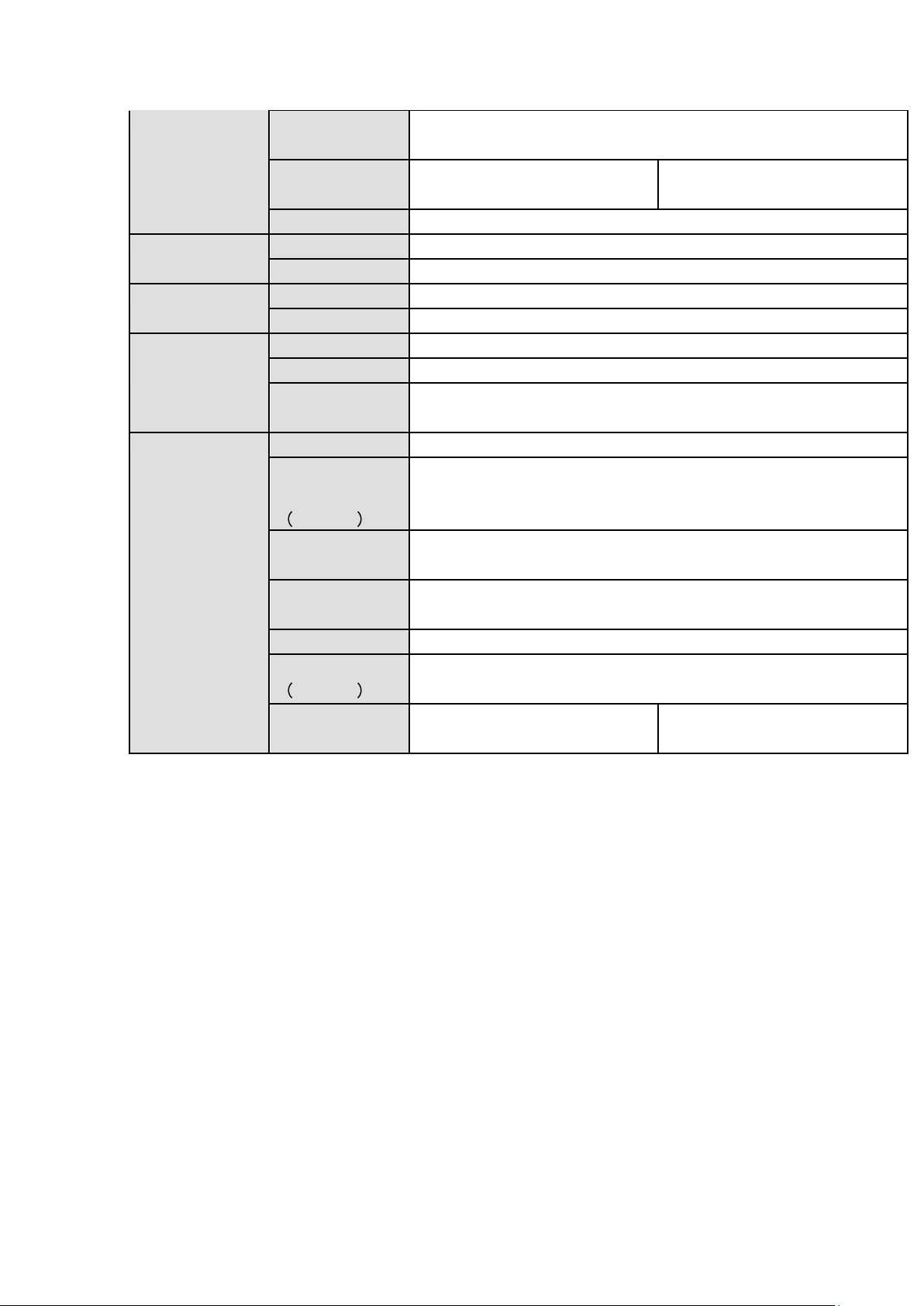
2 Overview and Controls
Icon
Name
Function
STATUS
Status indicator light
The blue light is on when the device is working
properly.
HDD
HDD status indicator
light
The blue light is on when the HDD is malfunction.
NET
Network status indicator
light
The blue light is on when the network connection is
abnormal.
POWER
Power status indicator light
The blue light is on when the power connection is
OK.
USB2.0 port
Connect to peripheral USB 2.0 storage device,
mouse, burner and etc.
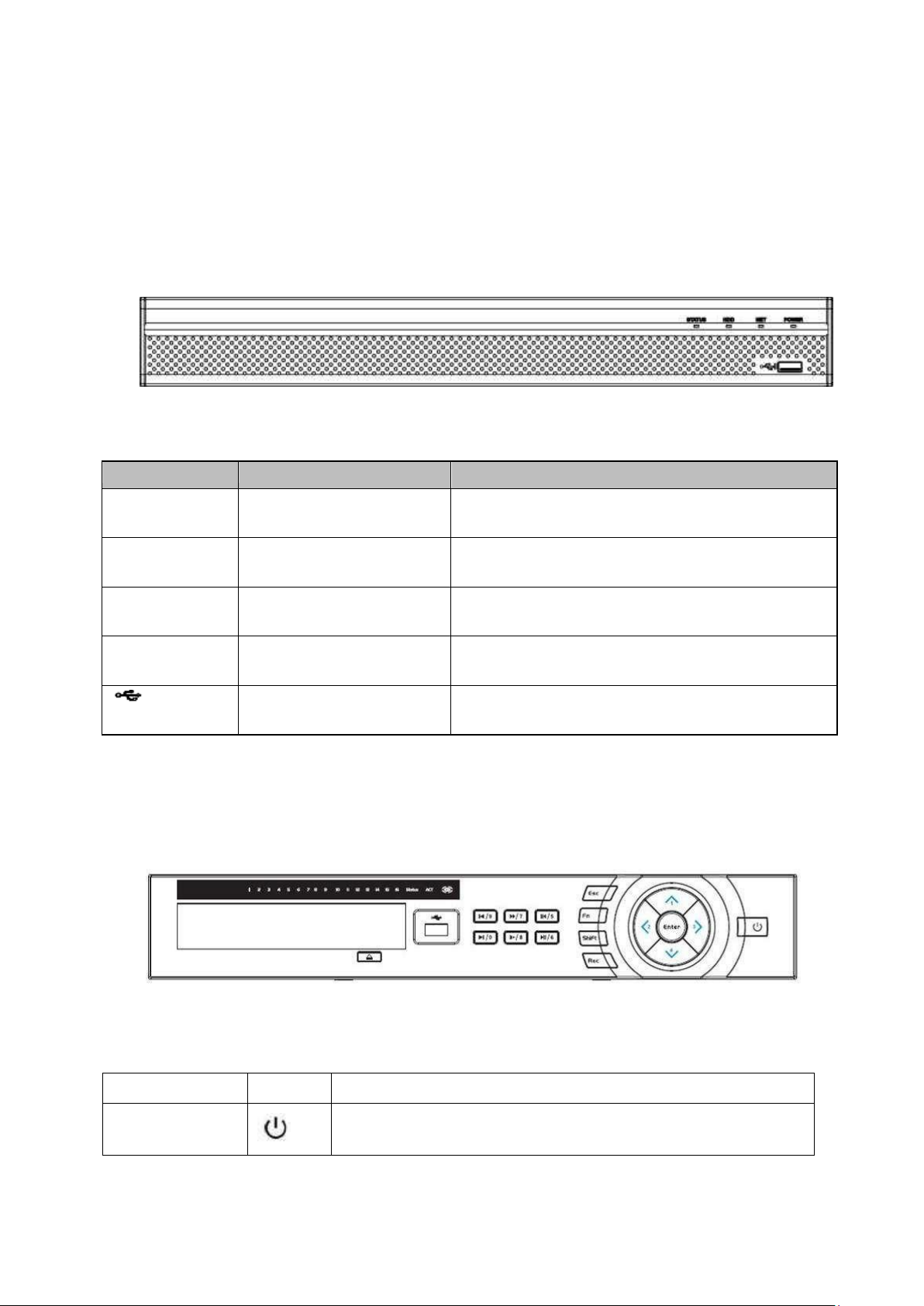
Name
Icon
Function
Power button
Power button, press this button for three seconds to boot up
or shut down DVR.
This section provides information about front panel and rear panel. When you install this series DVR
for the first time, please refer to this part first.
2.1 Front Panel
2.1.1
1U Series
The front panel is shown as below. See Figure 2-6.
Figure 2-6
Please refer to the following sheet for front panel button information.
2.1.2
The front panel is shown as in Figure 2-8.
Please refer to the following sheet for front panel button information.
General 1.5U Series
Figure 2-8
Page 30

20
Shift
Shift
In textbox, click this button to switch between numeral,
English(Small/Capitalized),donation and etc.
Up/1
Down/4
、
Activate current control, modify setup, and then move up and
down.
Increase/decrease numeral.
Assistant function such as PTZ menu.
In text mode, input number 1/4 (English character G/H/I)
Left/2
Right/3
Shift current activated control,
When playback, click these buttons to control playback bar.
In text mode, input number 2(English character A/B/C)
/3(English character D/E/F)
ESC
ESC
Go to previous menu, or cancel current operation.
When playback, click it to restore real-time monitor mode.
Enter
ENTER
Confirm current operation
Go to default button
Go to menu
Record
REC
Manually stop/start recording, working with direction keys
or numeral keys to select the recording channel.
Slow play/8
Multiple slow play speeds or normal playback.
In text mode, input number 8 (English character T/U/V).
Assistant
Fn
One-window monitor mode, click this button to display
assistant function: PTZ control and image color.
Backspace function: in numeral control or text control, press
it for 1.5seconds to delete the previous character before the
In motion detection setup, working with Fn and direction keys
to realize setup.
In text mode, click it to switch between numeral, English
character(small/capitalized) and etc.
Realize other special functions.
Fast play/7
Various fast speeds and normal playback.
In text mode, input number 7 (English character P/Q/R/S).
Play previous/0
|
In playback mode, playback the previous video
In text mode, input number 0.
Reverse/Pause/6
||
In normal playback or pause mode, click this button to
reverse
playback
In reverse playback, click this button to pause playback.
Page 31

21
Play Next/9
►│
In playback mode, playback the next video
In menu setup, go to down ward of the dropdown list.
In text mode, input number 9 (English character W/X/Y/Z)
Play/Pause /5
►||
In normal playback click this button to pause playback
In pause mode, click this button to resume playback.
In text mode, input number 5(English character J/K/L).
USB port
To connect USB storage device, USB mouse.
Network
abnormal
indication light
Net
Network error occurs or there is no network connection, the
light becomes red to alert you.
HDD abnormal
indication light
HDD
HDD error occurs or HDD capacity is below specified
threshold value, the light becomes red to alert you.
Record light
1-16
System is recording or not. It becomes on when system is
recording.
Icon
Name
Function
STATUS
Status indicator light
The blue light is on when the device is working
properly.
HDD
HDD status indicator
light
The blue light is on when the HDD is malfunction.
NET
Network status indicator
light
The blue light is on when the network connection is
abnormal.
POWER
Power status indicator light
The blue light is on when the power connection is
OK.
USB2.0 port
Connect to peripheral USB 2.0 storage device,
mouse, burner and etc.
2.1.3
General 2U Series
The front panel is shown as below. See Figure 2-10.
Figure 2-10
Please refer to the following sheet for front panel button information.
Page 32

22
2.2 Rear Panel
SN
Icon
Name
Function
1
VIDEO IN
Video input
port
Connect to analog camera, video input signal.
2
AUDIO IN
Audio input
port
Connect to microphone and etc to input signal.
3
HDMI
High definition
media
interface
High definition audio and video signal output port. It
transmits the same video signal as that of the VGA/TV or
different video signal from that of the VGA/TV(support
customized setup).
Support mouse operation.
4
Network port
1000M Ethernet port
5
VGA
VGA
VGA video output port
2.2.1
General 4MP 1U Series
The rear panel is shown as in Figure 2-83.
The following figure is based on the 8-channel series product.
Figure 2-83
Please refer to the following sheet for detailed information.
Page 33

23
SN
Icon
Name
Function
6
Power switch
Power on/off button.
7
GND
Power switch
Power on/off button.
8
AUDIO OUT
Audio output
port
Connect to sound box and etc to output audio signal.
9 A RS485
communicatio
n port
RS485_A port. It is the cable A. You can connect to the
control devices such as speed dome PTZ.
B
RS485_B.It is the cable B. You can connect to the control
devices such as speed dome PTZ.
10
USB3.0 port
Connect to mouse, USB storage media, USB-burner and
etc.
11
Power socket
Power input port
SN
Icon
Name
Note
1
Power switch
Power on/off button.
2
Power socket
Power socket
3
AUDIO IN
Audio input port
It is to receive the analog audio
signal output from the devices such
as microphone.
2.2.2
1.5U Series
The 8-channel 5-Way4-HDD 720P 1.5U rear panel is shown as below. See Figure 2-84.
Figure 2-84
Please refer to the following sheet for detailed information.
Page 34

24
SN
Icon
Name
Note
4
MIC OUT
Audio output port
Audio output port. It is to output the
analog audio signal to the devices
such as the sound box.
5
MIC IN
Audio input port
Bidirectional talk input port. It is to
receive the analog audio signal
output from the devices such as
microphone, pickup.
6
AUDIO OUT
Audio output port
Audio output port. It is to output the
analog audio signal to the devices
such as the sound box.
7
VIDEO OUT
Video output port
Connect to video output devices
such as TV.
8
1~8
Alarm input port 1~
8
There are two groups. The first
group is from port 1 to port 4;
the second group is from port 5
to port 8. They are to receive
the signal from the external
alarm source. There are two
types; NO (normal open)/NC
(normal close).
When your alarm input device
is using external power, please
make sure the device and the
NVR have the same ground.
NO1~NO5
Alarm output port
1~5
5 groups of alarm output ports.
(Group 1:port NO1~C1,Group
2:port NO2~ C2,Group 3:port
NO3 ~ C3, Group 4 : port
NO4~C4, Group 5: port NO5,
C5, NC5).Output alarm signal
to the alarm device. Please
make sure there is power to the
external alarm device.
NO: Normal open alarm output
port.
C: Alarm output public end.
NC: Normal close alarm output
port.
C1~C5
NC5
A
RS-485
communication port
RS485_A port. It is the cable A. You
can connect to the control devices
such as speed dome PTZ.
B
RS485_B.It is the cable B. You can
connect to the control devices such
as speed dome PTZ.
Page 35

25
SN
Icon
Name
Note
T+、T-、R+、R-
Four-wire full-duplex
485 port
Four-wire full-duplex 485 port. T+,
T- is the output wire.
R+,R- is the input wire.
CTRL 12V
Control power output
Controller 12V power output. It is to
control the on-off alarm relay
output.
12V
+12V power output
port
+12V power output port. It can
provide the power to some
peripheral devices such as the
camera or the alarm device. Please
note the supplying power shall be
below 1A.
G
Ground
Ground
9
RS-232
RS232 debug COM.
It is for general COM debug to
configure IP address or transfer
transparent COM data.
10
USB port
Connect to USB storage device,
mouse, burning DVD-ROM and etc.
11
eSATA
eSATA port
External SATA port. It can connect
to the device of the SATA port.
Please make sure there is power
supplying when there is peripheral
connected HDD.
12
HDMI 1
High Definition
Media Interface
High definition audio and video
signal output port. It transmits
uncompressed high definition video
and multiple-channel data to the
HDMI port of the display device.
13
VGA
VGA video output
port
VGA video output port. Output
analog video signal. Can connect to
the monitor to view ananlog video
output.
14
Network port
1000Mbps Ethernet port
15
VIDEO IN
Video input port
Connect to analog camera, video
input signal.
The 16-channel 5-Way4-HDD 720P 1.5U /8-channel 5-Way4-HDD 1080P 1.5U
/16-channel 5-Way4-HDD 1080P 1.5U rear panel is shown as below. See Figure 2-85.
Page 36

26
SN
Icon
Name
Note
1
AUDIO IN
Audio input port
It is to receive the analog audio
signal output from the devices such
as microphone.
2
MIC OUT
Audio output port
Audio output port. It is to output the
analog audio signal to the devices
such as the sound box.
3
MIC IN
Audio input port
It is to receive the analog audio
signal output from the devices such
as microphone.
4
AUDIO OUT
Audio output port
Audio output port. It is to output the
analog audio signal to the devices
such as the sound box.
5
VIDEO OUT
Video output port
Connect to video output devices
such as TV.
6
1~16
Alarm input port 1~
16
There are four groups. The first
group is from port 1 to port 4,
the second group is from port 5
to port 8, the third group is from
9 to 12, and the fourth group is
from 13 to 16. They are to
receive the signal from the
external alarm source. There
are two types; NO (normal
open)/NC (normal close).
When your alarm input device
is using external power, please
make sure the device and the
NVR have the same ground.
NO1~NO5
Alarm output port
1~5
5 groups of alarm output ports.
(Group 1:port NO1~C1,Group
2:port NO2~C2,Group 3:port
C1~C5
Figure 2-85
Please refer to the following sheet for detailed information.
Page 37

27
SN
Icon
Name
Note
NC5
NO3~C3, Group 4:port
NO4~C4, Group 5: port NO5,
C5, NC5).Output alarm signal
to the alarm device. Please
make sure there is power to the
external alarm device.
NO: Normal open alarm output
port.
C: Alarm output public end.
NC: Normal close alarm output
port.
A
RS-485
communication port
RS485_A port. It is the cable A. You
can connect to the control devices
such as speed dome PTZ.
B
RS485_B.It is the cable B. You can
connect to the control devices such
as speed dome PTZ.
T+、T-、R+、R-
Four-wire full-duplex
485 port
Four-wire full-duplex 485 port. T+,
T- is the output wire.
R+,R- is the input wire.
CTRL 12V
Control power output
Controller 12V power output. It is to
control the on-off alarm relay
output.
12V
+12V power output
port
+12V power output port. It can
provide the power to some
peripheral devices such as the
camera or the alarm device. Please
note the supplying power shall be
below 1A.
Ground
Ground
7
RS-232
RS232 debug COM.
It is for general COM debug to
configure IP address or transfer
transparent COM data.
8
eSATA
eSATA port
External SATA port. It can connect
to the device of the SATA port.
Please make sure there is power
supplying when there is peripheral
connected HDD.
9
USB port
Connect to USB storage device,
mouse, burning DVD-ROM and etc.
Page 38

28
SN
Icon
Name
Note
10
HDMI1
High Definition
Media Interface 1
High definition audio and video
signal output port. It outputs the
same video source as VGA/TV.
Support mouse operation and
control.
11
HDMI2
High Definition
Media Interface 2
High definition audio and video
signal output port. Support multiplewindow video matrix
output. Support tour function.
12
VGA
VGA video output
port
VGA video output port. Output
analog video signal. Can connect to
the monitor to view ananlog video
output.
13
Network port
1000Mbps Ethernet port
14
VIDEO IN
Video input port
Connect to analog camera, video
input signal.
15
Power switch
Power on/off button.
16
Power socket
Power socket
17
Ground terminal
Ground
The 32-channel 5-Way4-HDD 720P 1.5U rear panel is shown as below. See Figure 2-86.
SN
Icon
Name
Note
1
MIC OUT
Audio output port
Audio output port. It is to output the
analog audio signal to the devices
such as the sound box.
Figure 2-86
Please refer to the following sheet for detailed information.
Page 39

29
SN
Icon
Name
Note
2
MIC IN
Audio input port
Bidirectional talk input port. It is to
receive the analog audio signal
output from the devices such as
microphone, pickup.
3
VIDEO OUT
Video output port
Connect to video output devices
such as TV.
4
AUDIO OUT
Audio output port
Audio output port. It is to output the
analog audio signal to the devices
such as the sound box.
5
AUDIO IN
Audio input port
It is to receive the analog audio
signal output from the devices such
as microphone.
6
1~16
Alarm input port 1~
16
There are four groups. The first
group is from port 1 to port 4,
the second group is from port 5
to port 8, the third group is from
9 to 12, and the fourth group is
from 13 to 16. They are to
receive the signal from the
external alarm source. There
are two types; NO (normal
open)/NC (normal close).
When your alarm input device
is using external power, please
make sure the device and the
NVR have the same ground.
NO1~NO5
Alarm output port
1~5
5 groups of alarm output ports.
(Group 1:port NO1~C1,Group
2:port NO2~C2,Group 3:port
NO3~C3, Group 4:port NO4
~C4, Group 5: port NO5, C5,
NC5).Output alarm signal to
the alarm device. Please make
sure there is power to the
external alarm device.
NO: Normal open alarm output
port.
C: Alarm output public end.
NC: Normal close alarm output
port.
C1~C5
NC5
A
RS-485
communication port
RS485_A port. It is the cable A. You
can connect to the control devices
such as speed dome PTZ.
B
RS485_B.It is the cable B. You can
connect to the control devices such
as speed dome PTZ.
Page 40

30
SN
Icon
Name
Note
T+、T-、R+、R-
Four-wire full-duplex
485 port
Four-wire full-duplex 485 port. T+,
T- is the output wire.
R+,R- is the input wire.
CTRL 12V
Control power output
Controller 12V power output. It is to
control the on-off alarm relay
output.
12V
+12V power output
port
+12V power output port. It can
provide the power to some
peripheral devices such as the
camera or the alarm device. Please
note the supplying power shall be
below 1A.
Ground
Ground
7
VGA
VGA video output
port
VGA video output port. Output
analog video signal. Can connect to
the monitor to view ananlog video
output.
8
Power switch
Power on/off button.
9
Power socket
Power socket
10
Ground terminal
Ground
11
HDMI1
High Definition
Media Interface 1
High definition audio and video
signal output port. It outputs the
same video source as VGA/TV.
Support mouse operation and
control.
12
HDMI2
High Definition
Media Interface 2
High definition audio and video
signal output port. Support multiplewindow video matrix
output. Support tour function.
13
eSATA
eSATA port
External SATA port. It can connect
to the device of the SATA port.
Please make sure there is power
supplying when there is peripheral
connected HDD.
14
USB port
Connect to USB storage device,
mouse, burning DVD-ROM and etc.
Page 41

31
SN
Icon
Name
Note
15 RS-232
RS232 debug COM.
It is for general COM debug to
configure IP address or transfer
transparent COM data.
16
Network port
1000Mbps Ethernet port
17 VIDEO IN
Video input port
Connect to analog camera, video
input signal.
SN
Icon
Name
Note
2.2.3
The 8-channel 5-Way720P 2U rear panel is shown as below. See Figure 2-87.
2U Series
Figure 2-87
The 8-channel 5-Way1080P 2U/ 16-channel 5-Way1080P 2U rear panel is shown as
below. See Figure 2-88.
Please refer to the following sheet for detailed information.
Figure 2-88
Page 42

32
SN
Icon
Name
Note
1
Power switch
Power on/off button.
2
Power socket
Power socket
3
AUDIO IN
Audio input port
It is to receive the analog audio
signal output from the devices such
as microphone.
4
MIC IN
Audio input port
Bidirectional talk input port. It is to
receive the analog audio signal
output from the devices such as
microphone, pickup.
5
MIC OUT
Audio output port
Audio output port. It is to output the
analog audio signal to the devices
such as the sound box.
6
AUDIO OUT
Audio output port
Audio output port. It is to output the
analog audio signal to the devices
such as the sound box.
7
VIDEO OUT
Video output port
Connect to video output devices
such as TV.
8
1~8
Alarm input port 1~
8
There are two groups. The first
group is from port 1 to port 4;
the second group is from port 5
to port 8. They are to receive
the signal from the external
alarm source. There are two
types; NO (normal open)/NC
(normal close).
When your alarm input device
is using external power, please
make sure the device and the
NVR have the same ground.
NO1~NO5
Alarm output port
1~5
5 groups of alarm output ports.
(Group 1:port NO1~C1,Group
2:port NO2~ C2,Group 3:port
NO3 ~ C3, Group 4 : port
NO4~C4, Group 5: port NO5,
C1~C5
Page 43

33
SN
Icon
Name
Note
NC5
C5, NC5).Output alarm signal
to the alarm device. Please
make sure there is power to the
external alarm device.
NO: Normal open alarm output
port.
C: Alarm output public end.
NC: Normal close alarm output
port.
A
RS-485
communication port
RS485_A port. It is the cable A. You
can connect to the control devices
such as speed dome PTZ.
B
RS485_B.It is the cable B. You can
connect to the control devices such
as speed dome PTZ.
T+、T-、R+、R-
Four-wire full-duplex
485 port
Four-wire full-duplex 485 port. T+,
T- is the output wire.
R+,R- is the input wire.
CTRL 12V
Control power output
Controller 12V power output. It is to
control the on-off alarm relay
output.
12V
+12V power output
port
+12V power output port. It can
provide the power to some
peripheral devices such as the
camera or the alarm device. Please
note the supplying power shall be
below 1A.
G
Ground terminal
Ground
9
USB port
Connect to USB storage device,
mouse, burning DVD-ROM and etc.
10
eSATA
eSATA port
External SATA port. It can connect
to the device of the SATA port.
Please make sure there is power
supplying when there is peripheral
connected HDD.
11
HDMI 1
High Definition
Media Interface 1
High definition audio and video
signal output port. It outputs the
same video source as VGA/TV.
Support mouse operation and
control.
12
RS-232
RS232 debug COM.
It is for general COM debug to
configure IP address or transfer
transparent COM data.
Page 44

34
SN
Icon
Name
Note
13
VGA
VGA video output
port
VGA video output port. Output
analog video signal. Can connect to
the monitor to view ananlog video
output.
14
Network port
1000Mbps Ethernet port
15
VIDEO IN
Video input port
Connect to analog camera, video
input signal.
16
HDMI2
High Definition
Media Interface 2
High definition audio and video
signal output port. Support multiplewindow video matrix
output. Support tour function.
17
Ground terminal
Ground
The 32-channel 5-Way720P 2U rear panel is shown as below. See Figure 2-89.
SN
Icon
Name
Note
1
AUDIO OUT
Audio output port
Audio output port. It is to output the
analog audio signal to the devices
such as the sound box.
2
VIDEO OUT
Video output port
Connect to video output devices
such as TV.
3
MIC IN
Audio input port
Bidirectional talk input port. It is to
receive the analog audio signal
output from the devices such as
microphone, pickup.
4
MIC OUT
Audio output port
Audio output port. It is to output the
analog audio signal to the devices
such as the sound box.
Figure 2-89
Please refer to the following sheet for detailed information.
Page 45

35
SN
Icon
Name
Note
5
AUDIO IN
Audio input port
It is to receive the analog audio
signal output from the devices such
as microphone.
6
1~16
Alarm input port 1~
16
There are four groups. The first
group is from port 1 to port 4,
the second group is from port 5
to port 8, the third group is from
9 to 12, and the fourth group is
from 13 to 16. They are to
receive the signal from the
external alarm source. There
are two types; NO (normal
open)/NC (normal close).
When your alarm input device
is using external power, please
make sure the device and the
NVR have the same ground.
NO1~NO5
Alarm output port
1~5
5 groups of alarm output ports.
(Group 1:port NO1~C1,Group
2:port NO2~ C2,Group 3:port
NO3 ~ C3, Group 4 : port
NO4~C4, Group 5: port NO5,
C5, NC5).Output alarm signal
to the alarm device. Please
make sure there is power to the
external alarm device.
NO: Normal open alarm output
port.
C: Alarm output public end.
NC: Normal close alarm output
port.
C1~C5
NC5
A
RS-485
communication port
RS485_A port. It is the cable A. You
can connect to the control devices
such as speed dome PTZ.
B
RS485_B.It is the cable B. You can
connect to the control devices such
as speed dome PTZ.
T+、T-、R+、R-
Four-wire full-duplex
485 port
Four-wire full-duplex 485 port. T+,
T- is the output wire.
R+,R- is the input wire.
CTRL 12V
Control power output
Controller 12V power output. It is to
control the on-off alarm relay
output.
12V
+12V power output
port
+12V power output port. It can
provide the power to some
peripheral devices such as the
camera or the alarm device. Please
Page 46

36
SN
Icon
Name
Note
note the supplying power shall be
below 1A.
G
Ground
Ground
7
RS-232
RS232 debug COM.
It is for general COM debug to
configure IP address or transfer
transparent COM data.
8
VGA
VGA video output
port
VGA video output port. Output
analog video signal. Can connect to
the monitor to view ananlog video
output.
9
Power socket
Power socket
10
Power switch
Power on/off button.
11
Ground terminal
Ground
12
HDMI 1
High Definition
Media Interface 1
High definition audio and video
signal output port. It outputs the
same video source as VGA/TV.
Support mouse operation and
control.
13
HDMI2
High Definition
Media Interface 2
High definition audio and video
signal output port. Support multiplewindow video matrix
output. Support tour function.
14
USB port
Connect to USB storage device,
mouse, burning DVD-ROM and etc.
15
eSATA
eSATA port
External SATA port. It can connect
to the device of the SATA port.
Please make sure there is power
supplying when there is peripheral
connected HDD.
16
Network port
1000Mbps Ethernet port
17
VIDEO IN
Video input port
Connect to analog camera, video
input signal.
When connect the Ethernet port, please use crossover cable to connect the PC and use the straight
cable to connect to the switch or router.
Page 47

37
2.3 Connection Sample
2.3.1
Please refer to the following figure for detailed information. See Figure 2-94.
1U Series
Figure 2-94
Page 48

38
2.3.2
The connection sample is shown as below. See Figure 2-95.
The following interface is based on the 32-channel series product.
1.5U Series
Page 49

39
Figure 2-95
2.3.3
Please refer to the following figure for detailed information. See Figure 2-96.
The following interface is based on the 16-channel general 720P (V2) 2U series product.
2U Series
Page 50

40
Serial Number
Name
Function
1
Power button
Click it to boot up or shut down
the device.
2
Address
Click it to input device number, so
that you can control it.
F
i
g
u
r
e
2
9
6
2.4 Remote Control
The remote control interface is shown as in Figure 2-97.
Please note remote control is not our standard accessory and it is not
included in the accessory bag.
Figure 2-97
Page 51

41
3
Forward
Various forward speeds and
normal speed playback.
4
Slow play
Multiple slow play speeds or
normal playback.
5
Next record
In playback mode, playback the
next video.
6
Previous record
In playback mode, playback the
previous video.
7
Play/Pause
In pause mode, click this button
to realize normal playback.
In normal playback click this
button to pause playback.
In real-time monitor mode, click
this button to enter video search
menu.
Reverse/pause
Reverse playback pause mode,
8
click this button to realize normal
playback.
In reverse playback click this
button to pause playback.
9
Esc.
Go back to previous menu or
cancel current operation (close
upper interface or control)
10
Record
Start or stop record manually
In record interface, working with
the direction buttons to select the
record channel.
Click this button for at least 1.5
seconds, system can go to the
Manual Record interface.
11
Direction keys
Switch current activated control,
go to left or right.
In playback mode, it is to control
the playback process bar.
Aux function(such as switch the
PTZ menu)
12
Enter /menu key
go to default button
go to the menu
13
Multiple-window switch
Switch between multiple-window
and one-window.
14
Fn
In 1-ch monitor mode: pop up
assistant function : PTZ control
and Video color.
Switch the PTZ control menu in
PTZ control interface.
Page 52

42
In motion detection interface,
working with direction keys to
complete setup.
In text mode, click it to delete
character.
15
0-9 number key
Input password, channel or
switch channel.
Shift is the button to switch the
input method.
Left click
mouse
System pops up password input dialogue box if you have not logged in.
In real-time monitor mode, you can go to the main menu.
When you have selected one menu item, left click mouse to view menu
content.
Implement the control operation.
Modify checkbox or motion detection status.
Click combo box to pop up drop down list
2.5 Mouse Control
Page 53

43
In input box, you can select input methods. Left click the corresponding
button on the panel you can input numeral/English character
(small/capitalized). Here ← stands for backspace button. _ stands for
space button.
In English input mode: _stands for input a backspace icon and ←
stands for deleting the previous character.
In numeral input mode: _ stands for clear and ← stands for
deleting the previous numeral.
When input special sign, you can click corresponding numeral in the
front panel to input. For example, click numeral 1 you can input“/” , or
you can click the numeral in the on-screen keyboard directly.
Double left
click mouse
Implement special control operation such as double click one item in
the file list to playback the video.
In multiple-window mode, double left click one channel to view in fullwindow.
Double left click current video again to go back to previous
multiple-window mode.
Page 54

44
Right click
mouse
In real-time monitor mode, pops up shortcut menu: one-window, fourwindow, nine-window and sixteen-window, Pan/Tilt/Zoom, color
setting, search, record, alarm input, alarm output, main menu.
Among which, Pan/Tilt/Zoom and color setting applies for current
selected channel.
If you are in multiple-window mode, system automatically switches to
the corresponding channel.
Exit current menu without saving the modification.
Press
middle
button
In numeral input box: Increase or decrease numeral value.
Switch the items in the check box.
Page up or page down
Move
mouse
Select current control or move control
Drag
mouse
Select motion detection zone
Select privacy mask zone.
2.6 Virtual Keyboard & Front Panel
2.6.1
The system supports two input methods: numeral input and English character (small and
capitalized) input.
Move the cursor to the text column, the text is shown as blue, input button pops up on the
right. Click that button to switch between numeral input and English input (capitalized and
small), Use > or < to shift between small character and capitalized character.
2.6.2
Move the cursor to the text column. Click Fn key and use direction ke ys to select number
you wanted. Please click enter button to input.
Virtual Keyboard
Front Panel
Page 55

45
3 Installation and Connections
Note: All the installation and operations here should conform to your local electric
safety rules.
3.1 Check Unpacked DVR
When you receive the DVR from the forwarding agent, please check whether there is any
visible damage. The protective materials used for the package of the DVR can protect
most accidental clashes during transportation. Then you can open the box to check the
accessories.
Please check the items in accordance with the list. Finally you can remove the protective
film of the DVR.
Note
Remote control is not a standard accessory and it is not included in the accessory bag.
3.2 About Front Panel and Real Panel
The model in the front panel is very important; please check according to your purchase
order.
The label in the rear panel is very important too. Usually we need you to represent the
serial number when we provide the service after sales.
3.3 HDD Installation
Important
Shut down the device and then unplug the power cable before you open the case to
replace the HDD!
All figures listed below for reference only!
This series DVR has 1 to 8 HDDs (no limitation for capacity). Please use HDD of 7200rpm
or higher. Usually we do not recommend the HDD for the PC. You can refer to the
Appendix for recommended HDD brand.
Please follow the instructions listed below to install hard disk.
3.3.1
Please make sure the metal surface of the HDD is facing up when you are installing!
This series product has only one 2.5-inch SATA HDD.
Please follow the instructions below to install HDD.
Smart Box Series
Page 56

46
3
Pu
t the
1
○
Draw ou
t the
HDD bracke
t
2 M
ake
s
ure
○
surface is facing up and then put
the HDD into the bracket
horizontally. After the HDD is in
the proper position, the columns
on the two sides can lock the
screw holes of the HDD to secure
it.
the
HDD
metal
○
device.
HDD in
When you remove the HDD, please refer to the following figure to pull the spring up and
then remove the HDD.
to th
e
3.3.2
The series DVR has one SATA HDD.
1 .
○
cover and side panel.
Smart 1U Series
Loosen
the sc
rew
s of the
upper
2 Fix fo
○
(Turn just three rounds).
ur screw
s in the
HDD
3
Place
○
accordance with the four holes in
the bottom.
the
HDD
in
Page 57

47
4 T
urn
○
then turn the screws in firmly.
7 P
○
the clip and then place the upper cover
back.
3.3.3
the device ups
u
t the cov
er in accordance wi
Compact 1U and Mini 1U Series
The series DVR has one SATA HDD.
ide down and
th
5 Fix t
○
8
○
he HDD firml
Secure the
sc
y.
rews in
6
Conne
○
power cable.
the r
ear panel and the side panel
ct the
HDD cable and
.
①Loosen the screws of the upper cover
and side panel.
②Fix four screws in the HDD (Turn
just three rounds).
③Place the HDD in accordance
with the four holes in the bottom.
Page 58

48
④Turn the device upside down and
then turn the screws in firmly.
⑤Fix the HDD firmly. ⑥Connect the HDD cable and
power cable.
⑦Put the cover in accordance with the
clip and then place the upper cover
back.
⑧Secure the screws in the rear panel
and the side panel.
Important:
You can connect the HDD data cable and the power cable first and then fix the HDD
in the device.
Please pay attention to the front cover. It adopts the vertical sliding design. You need
to push the clip first and then put down.
3.3.4
The 1U series DVR has two SATA HDDs.
1U Series
Loosen the screws of the upper
cover and side panel. Remove
the cover.
Fix four screws in the HDD
(Turn just three rounds).
Place the HDD in accordance
with the four holes in the bottom.
Page 59

49
Turn the device upside down and
then turn the screws in firmly.
Connect the HDD cable and
power cable. .
Put the cover in accordance
with the clip and then place the
upper cover back. Secure the
screws in the rear panel and the
side panel.
3.3.5
This series DVR max has four SATA HDDs. Please use HDD of 7200rpm or higher.
1 Lo
○
4 Conn
○
1.5U series
osen the screws
upper cover. Remove the
cover.
ect the
of
the
other end of
2 Li
ne
up
○
four holes of the HDD
bracket. Use four screws to
fix HDD.
5 Conn
○
the HDD
ect the power cable
to t
he
3 Conn
○
cable to the HDD.
.
6 Put th
○
ect the
one end of the
e cover
b
ack a
HDD
nd fix
the
the HDD cable to the
mainboard.
3.3.6
2U series
to the HDD.
screws to secure firmly.
This series DVR max supports 8 SATA HDDs. Please use HDD of 7200rpm or higher.
① Loosen the screws of the
upper cover and side panel.
Remove the cover.
② Fix the HDD(s) on the
bracket. Remove the top
bracket if you want to install
③Connect the one end of the HDD
cable to the HDD.
Page 60

50
HDD to the bottom bracket.
4
Conn
○
HDD cable to the mainboard.
ect the other e
nd of th
⑤Connect the power cable to the
e
HDD.
⑥Put the cover back and fix the
screws to secure firmly.
Important:
If the HDD amount is less than four, you do not need to install the HDD bracket.
When there is a bracket, please make sure the installation direction of HDDs is the same.
3.3.7
The DVR occupies 1.5U/2U rack units of vertical rack space.
Please make sure the indoor temperature is below 35℃ (95°f).
Rack Installation
Use twelve screws to fix the unit
Please make sure there is 15cm (6 inches) space around the device to guarantee
sound ventilation.
Please install from the bottom to the top.
If there are more accessories connected in the rack, please take precaution
measures in case the rack power is overload.
3.4 Connecting Power Supply
Please check input voltage and device power button match or not.
We recommend you use UPS to guarantee steady operation, DVR life span, and other
peripheral equipments operation such as cameras.
3.5 Connecting Video Input and Output Devices
3.5.1
The video input interface is BNC. The input video format includes: PAL/NTSC BNC
(1.0VB
The input video format: BNC(0.8VP-P,75Ω),
The video signal should comply with your national standards.
The input video signal shall have high SNR, low distortion; low interference, natural color
and suitable lightness.
Guarantee the stability and reliability of the camera signal:
The camera shall be installed in a cool, dry place away from direct sunlight, inflammable,
Connecting Video Input
B75Ω.).
P- P
,
Page 61

51
explosive substances and etc.
The camera and the DVR should have the same grounding to ensure the normal
operation of the camera.
Guarantee stability and reliability of the transmission lineBTTTB
Please use high quality, sound shielded BNC. Please select suitable BNC model
according to the transmission distance.
If the distance is too long, you should use twisted pair cable, and you can add video
compensation devices or use optical fiber to ensure video quality.
You should keep the video signal away from the strong electromagnetic interference,
especially the high tension current.
Keep connection lugs in well contactBTTTB
The signal line and shielded wire should be fixed firmly and in well connection. Avoid dry
joint, lap welding and oxidation.BTTT
3.5.2
Video output includes a TBNC(PAL/NTSC, 1.0VP- P, 75Ω)output, a VGA output and a
HDMI output.
System supports BNC, VGA and HDMI output at the same time.
When you are using pc-type monitor to replace the monitor, please pay attention to the
following points:
Using TV as video output device is not a reliable substitution method. You also need to
reduce the working hour and control the interference from power supply and other devices.
The low quality TV may result in device damage.
Connecting Video Output
To defer aging, do not allow the pc monitor to run for a long time.
Regular demagnetization will keep device maintain proper status.
Keep it away from strong electromagnetic interference devices.
3.6 Connecting Audio Input & Output, Bidirectional Audio
3.6.1
BNC port is adopted for audio input port.
Due to high impedance of audio input, please use active sound pick-up.
Audio transmission is similar to video transmission. Try to avoid interference, dry joint,
loose contact and it shall be away from high tension current.
3.6.2
The audio output signal parameter is usually over 200mv 1KΩ (BNC). It can directly
connect to low impedance earphone, active sound box or amplifier-drive audio output
device.
If the sound box and the pick-up cannot be separated spatially, it is easy to arouse
squeaking. In this case you can adopt the following measures:
Audio Input
Audio Output
Use better sound pick-up with better directing property.
Reduce the volume of the sound box.
Using more sound-absorbing materials in decoration can reduce voice echo and
improve acoustics environment.
Adjust the layout to reduce happening of the squeaking.
Page 62

52
3.7 Alarm Input and Output Connection
Please read the followings before connecting.
1. Alarm input
a. Please make sure alarm input mode is grounding alarm input.
b. Grounding signal is needed for alarm input.
c. Alarm input needs the low level voltage signal.
d. Alarm input mode can be either NC (normal Open) or NO (Normal Close)
e. When you are connecting two DVRs or you are connecting one DVR and one other
device, please use a relay to separate them,
2. Alarm output
The alarm output port should not be connected to high power load directly (It shall be less
than 1A) to avoid high current which may result in relay damage. Please use the co
contactor to realize the connection between the alarm output port and the load.
3. How to connect PTZ decoder
a. Ensure the decoder has the same grounding with DVR, otherwise you may not control
the PTZ. Shielded twisted wire is recommended and the shielded layer is used to connect
to the grounding.
b. Avoid high voltage. Ensure proper wiring and some thunder protection measures.
c. For too long signal wires, 120Ω should be parallel connected between A, B lines on the
far end to reduce reflection and guarantee the signal quality.
d. “485 A, B” of DVR cannot parallel connect with “485 port” of other device.
e. The voltage between of A,B lines of the decoder should be less than 5v.
4. Please make sure the front-end device has soundly earthed.
Improper grounding may result in chip damage.
3.7.1
Important
Please refer to the specifications for the alarm input and output channel amount.
Do not merely count the alarm input and out channel amount according to the ports
on the rear panel.
Alarm Input and Output Details
Page 63

53
1,2,3,4,5,6,
7,8,9,10,11,
12,13,14,15,16
ALARM 1 to ALARM 16. The alarm becomes active in low voltage.
In the second line,
from the left to the
right:
NO1 C1,
NO2 C2,
NO3 C3,
NO4 C4,
NO5 C5,
NO6 C6.
There are six groups of normal open activation output (on/off button)
CTRL 12V
Control power output. For external alarm, you need to close the
device power to cancel the alarm.
Voltage current;500mA.
+12V
Rated current.
Voltage current;500mA.
Earth cable.
485 A/B
485 communication port. They are used to control devices such as
decoder. 120Ω should be parallel connected between A, B lines if
there are too many PTZ decoders.
T+,T-,R+,R-
They are four-wire full-duplex RS485 port
T+ T-: output wire
R+ R-: input wire
Figure 3-1
3.7.2
Please refer to the following sheet for more information.
Grounding alarm inputs. Normal open or Normal close type)
Please parallel connect COM end and GND end of the alarm detector (Provide
Please parallel connect the Ground of the DVR and the ground of the alarm detector.
Alarm Input Port
external power to the alarm detector).
Page 64

54
Please connect the NC port of the alarm sensor to the DVR alarm input(ALARM)
Model
HFD23/005-1ZS
HRB1-S-DC5V
Material of the touch
AgNi+ gold-plating
AuAg10/AgNi10/CuNi30
Rating
(Resistance
Load)
Rated switch
capacity
30V DC 1A/125V AC 0.5A
24V DC 1A/125V AC 2A
Maximum
switch power
62.5VA/30W
250VA/48W
Maximum
switch voltage
125V AC/60V DC
125V AC/60V DC
Maximum
switch
currency
2A 2A
Insulation
Between
touches
400VAC 1 minute
500VAC 1 minute
Between touch
and winding
1000VAC 1 minute
1000VAC 1 minute
Turn-on Time
5ms max
5ms max
Turn-off Time
5ms max
5ms max
Longevity
Mechanical
1×10⁷times
times/MIN)
(
300
5×10
6
times
times/MIN)
(
300
Electrical
1×10
5
times
times/MIN)
(
30
2.5×10
4
times
times/MIN)
(
30
Use the same ground with that of DVR if you use external power to the alarm device.
Figure 3-2
3.7.3
Alarm Output Port
Provide external power to external alarm device.
To avoid overloading, please read the following relay parameters sheet carefully.
RS485 A/B cable is for the A/B cable of the PTZ decoder.
T+,T-,R+,R- are four-wire double duplex RS485 port.
T+ T-: output wire
R+ R-: input wire
Relay Specification
Page 65

55
Model
HFD23/005-1ZS
HRB1-S-DC5V
Working Temperature
-30℃~+70℃
-40℃~+70℃
485 Port
3.8 RS485
When the DVR receives a camera control command, it transmits that command up the coaxial
cable to the PTZ device. RS485 is a single-direction protocol; the PTZ device can’t return any
data to the unit. To enable the operation, connect the PTZ device to the RS485 (A,B) input on
the DVR.
Since RS485 is disabled by default for each camera, you must enable the PTZ settings first.
This series DVRs support multiple protocols such as Pelco-D, Pelco-P.
To connect PTZ devices to the DVR:
1. Connect RS485 A,B on the DVR rear panel.
2. Connect the other end of the cable to the proper pins in the connector on the camera.
3. Please follow the instructions to configure a camera to enable each PTZ device on the
DVR.
Figure 3-3
3.9 Other Interfaces
There are still other interfaces on the DVR, such as USB ports.
Page 66

56
4 Overview of Navigation and Controls
4.1 Boot up and Shutdown
4.1.1
Before the boot up, please make sure:
Please follow the steps listed below to boot up the device.
4.1.2
Note
When you see corresponding dialogue box “System is shutting down…” Do not click
Boot up
The rated input voltage matches the device power on-off button. Please make sure
the power wire connection is OK. Then click the power on-off button.
Always use the stable current, if necessary UPS is a best alternative measure.
Connect the device to the monitor and then connect a mouse.
Connect power cable.
Click the power button at the front or rear panel and then boot up the device. After
device booted up, the system is in multiple-channel display mode by default.
Shutdown
power on-off button directly.
Do not unplug the power cable or click power on-off button to shutdown device
directly when device is running (especially when it is recording.)
There are three ways for you to log out.
a) Main menu (RECOMMENDED)
From Main Menu->Shutdown, select shutdown from dropdown list.
Click OK button, you can see device shuts down.
b) From power on-off button on the front panel or remote control
Press the power on-off button on the DVR front panel or remote control for more than 3
seconds to shutdown the device.
c) From power on-off button on the rear panel.
4.1.3
The system can automatically backup video and resume previous working status after
power failure.
Auto Resume after Power Failure
4.1.4
Please make sure to use the same battery model if possible.
We recommend replace battery regularly (such as one-year) to guarantee system time
accuracy.
Note:
Before replacement, please save the system setup, otherwise, you may lose the
data completely!
Replace Button Battery
4.2 Set/Reset Password
Page 67

57
4.2.1
For your own safety, please set your administrator default password after you first
boot up the device.
After system booted up, you can see the following interface if it is your first time to use or
you have restored default setup. See Figure 4-1. Please input a password and then input
again to set a password.
Set Password
You can set security questions here to reset the password in case you forgot. System
supports customized setup. Please note you need to set two security questions at the
same time. When you reset the password, you need to answer these two security
questions too.
For reset information, please refer to chapter 4.2.2.
Figure 4-1
After you complete the setup, click OK button, system pops up the following interface for
you to confirm. Click OK button to exit. See Figure 4-2.
Figure 4-2
Page 68

58
4.2.2
Once you forgot password, you can answer the security questions you set in chapter 4.2.1
to reset the password.
In login interface, . See Figure 4-3.
Reset Password
Figure 4-3
System pops up the following dialogue box, please answer the security questions and
then input the new password twice. See Figure 4-4.
Figure 4-4
4.3 Startup Wizard
After device successfully booted up, it goes to startup wizard.
Page 69

59
Click Cancel/Next button, you can see system goes to login interface.
Tips
Check the box Startup button here, system goes to startup wizard again when it boots up
the next time.
Cancel the Startup button, system goes to the login interface directly when it boots up the
next time.
Figure 4-5
Click Cancel button or Next Step button, system goes to login interface. See Figure 4-6.
System consists of three accounts:
Username: admin. Password: admin. (administrator, local and network)
Username: 888888. Password: 888888. (administrator, local only)
Username: default. Password: default (hidden user). Hidden user “default” is for
system interior use only and can not be deleted. When there is no login user, hidden
user “default” automatically login. You can set some rights such as monitor for this
user so that you can view some channel view without login.
Figure 4-6
Page 70

60
Caution
For security reason, please modify password after you first login.
Continuous three times login failure will result in system alarm and five times
login failure will result in account lock!
Please reboot the device or wait for 30 minutes to try again if your account has
been locked.
After input corresponding user name and password, you can click OK button. System
goes to the startup wizard.
When there are all analog channels, the startup wizard includes general, encode,
schedule, record control, network, P2P.
When there is an IP channel, the startup wizard includes general, network, P2P,
remote device and schedule.
Click OK button, you can go to General interface. See Figure 4-7.
For detailed information, please refer to chapter 4.11.5.1.
Figure 4-7
Note
You can only see the remote device interface if you have set IP channel (Chapter
4.11.1.3.5)
Click Next button, you can go to network interface. See Figure 4-8.
Page 71

61
For detailed information, please refer to chapter 4.10.3.
Figure 4-8
Click Next button, you can set P2P function. Scan the QR code, download the App to the
cellphone, you can use the smart phone to add the device. See Figure 4-9.
For detailed information, please refer to chapter4.11.2.15.
Figure 4-9
Page 72

62
Now you can go to the remote device interface to add the camera to the corresponding
channel. See Figure 4-10.
For detailed information, please refer to chapter4.11.1.1.
Please note you can not see the following interface if there is no digital channel. You can
go to Main menu->Setting->Camera->Channel type to set IP channel first. Please refer to
chapter 4.11.1.3.5 for detailed setup information.
Figure 4-10
Click Next button, you can go to Encode interface. See Figure 4-11.
For detailed information, please refer to chapter 4.11.1.3.
Page 73

63
Figure 4-11
Click Next button, you can go to Schedule interface. See Figure 4-12.
For detailed information, please refer to chapter 4.11.4.1.
Figure 4-12
Page 74

64
Click Finish button, system pops up a dialogue box. Click the OK button, the startup
1
Recording status
3
Video loss
2
Motion detection
4
Camera lock
wizard is complete. See Figure 4-13.
Figure 4-13
4.4 Live Viewing
After you logged in, the system is in live viewing mode. You can see system date, time,
channel name and window No. If you want to change system date and time, you can
refer to general settings (Main Menu->Setting->System->General). If you want to
modify the channel name, please refer to the display settings (Main Menu->Camera>CAM name)
Tips
Preview drag: If you want to change position of channel 1 and channel 2 when you
are previewing, you can left click mouse in the channel 1 and then drag to channel
2, release mouse you can switch channel 1 and channel 2 positions.
Use mouse middle button to control window split: You can use mouse middle
button to switch window split amount.
Please note you can not switch position of one analog channel and one digital
channel.
Preview Control
The preview control function has the following features.
Support preview playback.
In the preview desktop, system can playback previous 5-60 minutes record of
current channel. Please go to the Main Menu->General to set real-time
playback time.
Support drag and play function. You can use your mouse to select any
playback start time.
Support playback, pause and exit function.
Page 75

65
Right now, system does not support slow playback and backward playback
1 2 3 4 5
1 2 3 4 6 7
function.
Support digital zoom function.
Support real-time backup function.
You can follow the contents listed below for the operation instruction.
Preview control interface
Move you mouse to the top center of the video of current channel, you can see system
pops up the preview control interface. See Figure 4-14 and Figure 4-15. If your mouse
stays in this area for more than 6 seconds and has no operation, the control bar
automatically hides.
Figure 4-14 Analog Channel
Figure 4-15 Digital Channel
1) Realtime playback
It is to playback the previous 5-60 minutes record of current channel.
Please go to the Main menu->Setting->->System->General to set real-time playback
time.
System may pop up a dialogue box if there is no such record in current channel.
2) Digital zoom
It is to zoom in specified zone of current channel. It supports zoom in function of multiplechannel.
Click , the button is shown .
There are two ways for you to zoom in.
Drag the mouse to select a zone, you can view an interface show as Figure 4-16.
Figure 4-16
Page 76

66
Put the middle button at the center of the zone you want to zoom in, and move the
mouse, you can view an interface shown as in Figure 4-17.
Figure 4-17
Right click mouse to cancel zoom and go back to the original interface.
3) Manual record function
It is to backup the video of current channel to the USB device. System can not backup
the video of multiple-channel at the same time.
Click , system begins recording. Click it again, system stops recoridng. You can
find the record file on the flash disk.
4) Manual Snapshot
Click to snapshot 1-5 times. The snapshot file is saved on the USB device or HDD.
You can go to the Search interface (chapter 4.9.1) to view.
5) Mute (For analog channel only)
Click to mute. Click again to enable audio function when preview.
Please note this function is for one-window mode only.
6) Bidirectional talk (For digital channel only)
If the connected front-end device supports bidirectional talk function, you can click this
button. Click button to start bidirectional talk function the icon now is shown as .
Now the rest bidirectional talk buttons of digital channel becomes null too.
Click again, you can cancel bidirectional talk and the bidirectional talk butto ns of
other digital channels become .
7) Remote device (For digital channel only)
Shortcut menu. Click it to go to the remote device interface to add/delete remote
device or view its corresponding information. Please refer to chapter 4.11.1.1 for
detailed information.
4.5 Right-Click Menu
On the preview interface, right click mouse, you can view menu interface shown as in
Figure 4-18.
Tips
Page 77

67
After you go to the corresponding interface, right click mouse to go back to the upperlevel.
Window split mode: You can select window amount and then select channels.
PTZ: Click it to go to PTZ interface.
Auto focus: Please make sure you connected network camera supports this function.
Color setting: Set video corresponding information.
Search: Click it to go to Search interface to search and playback a record file.
Record control: Enable/disable record channel.
Remote device: Click it to add remote device.
Main menu: Go to system main menu interface.
4.5.1
Window Switch
Figure 4-18
System supports 1/4/8/9-window (The options here depend on your product channel
amount). You can select from the dropdown list. See Figure 4-19.
Page 78

68
Figure 4-19
4.5.2
Click it to go to the previous screen/next screen. For example, if you are using 4-split
mode, the first screen is displaying the channel 1-4, click Next screen, you can view
channel 5-8.
Previous Screen/Next Screen
4.5.3
The PTZ setup is shown as in See Figure 4-20.
Please note the commend name is grey once device does not support this function.
The PTZ operation is only valid in one-window mode.
PTZ Control
Here you can control PTZ direction, speed, zoom, focus, iris, preset, tour, scan, pattern
aux function, light and wiper, rotation and etc.
Speed is to control PTZ movement speed. The value ranges from 1 to 8.The speed 8 is
faster than speed 1. You can use the remote control to click the small keyboard to set.
You can click and of the zoom, focus and iris to zoom in/out, definition and
brightness.
The PTZ rotation supports 8 directions. If you are using direction buttons on the front
panel, there are only four directions: up/down/left/right.
Page 79

69
Name
Function
key
function
Shortcut
key
Function
key
function
Shortcut
key
Zoom
Near
Far Focus
Near
Far
►
Iris
close
Open
Figure 4-20
In the middle of the eight direction arrows, there is a 3D intelligent positioning key. See
Figure 4-21. Please make sure your protocol supports this function and you need to use
mouse to control.
Click this key, system goes back to the single screen mode. Drag the mouse in the screen
to adjust section size. The dragged zone supports 4X to 16X speeds. It can realize PTZ
automatically. The smaller zone you dragged, the higher the speed.
Figure 4-21
In Figure 4-20, click to open the menu, you can set preset, tour, pattern, scan and
etc. See Figure 4-22.
Figure 4-22
Please refer to the following sheet for detailed information.
Page 80

70
Please note the above interface may vary due to different protocols. The button is grey
Icon
Function
Icon
Function
Preset
Flip
Tour
Reset
Pattern
Aux
Scan
Aux on-off
button
Rotate
Go to menu
and can not be selected once the current function is null.
Right click mouse or click the ESC button at the front panel to go back to the Figure 4-
20.
4.5.3.1
PTZ Function Setup
Click , you can go to the following interface to set preset, tour, pattern, and scan. See
Figure 4-23.
Figure 4-23
Preset Setup
In Figure 4-23, click preset button and use eight direction arrows to adjust camera to the
proper position. The interface is shown as in Figure 4-24.
Click Set button and then input preset number.
Click Set button to save current preset.
Page 81

71
Figure 4-24
Tour Setup
In Figure 4-23, click tour button.
Input tour value and preset No. Click Add preset button to add current preset to the tour.
See Figure 4-25.
Tips
Repeat the above steps to add more presets to the tour. Click Del preset button to remove
it from the tour. Please note some protocols do not support delete preset function.
Figure 4-25
Pattern Setup
In Figure 4-23, click Pattern button and input pattern number.
Click Begin button to start direction operation. Or you can go back to Figure 4-20 to
operate zoom/focus/iris/direction operation.
In Figure 4-23, click End button.
Page 82

72
Figure 4-26
Scan Setup
In Figure 4-23, click Scan button.
Use direction buttons to set camera left limit and then click Left button.
Use direction buttons to set camera right limit and then click Right button. Now the scan
setup process is complete.
Figure 4-27
4.5.3.2
Call Preset
Call PTZ Function
In Figure 4-22, input preset value and then click to call a preset. Click
again to stop call.
Call Pattern
In Figure 4-22, input pattern value and then click to call a pattern. Click
again to stop call.
Call Tour
Page 83

73
In Figure 4-22, input tour value and then click to call a tour. Click again
to stop call.
Call Scan
In Figure 4-22, input Scan value and then click to call a tour. Click again
to stop call.
Rotate
In Figure 4-22, click to enable the camera to rotate.
System supports preset, tour, pattern, scan, rotate, light and etc function.
Note:
Preset, tour and pattern all need the value to be the control parameters. You can
define it as you require.
You need to refer to your camera user’s manual for Aux definition. In some cases, it
can be used for special process.
Aux
Click , system goes to the following interface. The options here are defined by the
protocol. The aux number is corresponding to the aux on-off button of the decoder. See
Figure 4-28.
Figure 4-28
4.5.4
It is to set auto focus function. Please make sure the camera supports this function.
Auto Focus
4.5.5
Here you can set hue, brightness, contrast, saturation, gain, white level, color mode
and etc. See Figure 4-29.
Color
Page 84

74
Item
Note
Period
There are two periods in one day. You can set different
sharpness, brightness, and contrast setup for different
periods.
Effective Time
Check the box here to enable this function and then set
period time.
Sharpness
The value here is to adjust the edge of the video. The
value ranges from 0 to 100. The larger the value is, the
clear the edge is and vice versa. Please note there is
noise if the value here is too high. The default value is 50
and the recommended value ranges from 40 to 60.
Brightness
It is to adjust monitor window bright. The value ranges
from 0 to 100. The default value is 50.
The larger the number, the bright the video is. When you
input the value here, the bright section and the dark
section of the video will be adjusted accordingly. You
can use this function when the whole video is too dark or
too bright. Please note the video may become hazy if the
value is too high. The recommended value ranges from
40 to 60.
Contrast
It is to adjust monitor window contrast. The value ranges
Figure 4-29
Please refer to the following sheet for detailed information.
Page 85

75
Item
Note
from 0 to 100. The default value is 50.
The larger the number, the higher the contrast is. You
can use this function when the whole video bright is OK
but the contrast is not proper. Please note the video may
become hazy if the value is too low. If this value is too
high, the dark section may lack brightness while the
bright section may over exposure .The recommended
value ranges from 40 to 60.
Saturation
It is to adjust monitor window saturation. The value
ranges from 0 to 100. The default value is 50.
The larger the number, the strong the color is. This value
has no effect on the general brightness of the whole
video. The video color may become too strong if the
value is too high. For the grey part of the video, the
distortion may occur if the white balance is not accurate.
Please note the video may not be attractive if the value
is too low. The recommended value ranges from 40 to
60.
Gain
The gain adjust is to set the gain value. The default
value may vary due to different device models. The
smaller the value, the low the noise. But the brightness is
also too low in the dark environments. It can enhance
the video brightness if the value is high. But the video
noise may become too clear.
Color mode
It includes several modes such as standard, color, bright,
gentle. Select a color mode, the sharpness, brightness,
contrast and etc can automatically switch to
corresponding setup.
EQ
Click or to adjust image equalization value.
Click reset , system can auto adjust the video
to the best effect.
This function is for analog channel only.
Image position
It is to adjust the image position on the screen. The
value here refers to the pixel. The default pixel value is
16.
This function is for analog channel only.
4.5.6
It is to set display output mode. There are two modes: full screen (4:3)/image original rate
(16:9). Icon means current display output mode. See Figure 4-30.
Display
Page 86

76
Figure 4-30
4.5.7
It is to display human face record list, and view human face recognition record file.
Face Search
4.5.8
Please refer to chapter 4.9.1 for detailed information.
Search
4.5.9
Please refer to chapter 4.11.4.3 for detailed information.
4.5.10
Please refer to chapter 4.11.3.6 for detailed information.
Record Control
Alarm Output
4.5.11
Please refer to chapter 4.11.1.1 for detailed information.
Remote Device
4.5.12
Please refer to chapter 4.11.5.3 for detailed information.
Video Matrix
4.5.13
Please refer to chapter 4.8 for detailed information.
Main menu
4.6 Navigation Bar
You need to go to the Main menu->Setting->System->General to enable navigation
bar function; otherwise you can not see the following interface.
The navigation bar is shown as below. See Figure 4-31.
Page 87

77
Figure 4-31
4.6.1
Click button to go to the main menu interface.
4.6.2
Select corresponding window-split mode and output channels.
4.6.3
Click to go to the previous screen, click to go to the next screen. For
example, if you are using 4-split mode, the first screen is displaying the channel 1-4,
click , you can view channel 5-8.
4.6.4
Click button to enable tour, the icon , you can see the tour is in
process.
4.6.5
Click , system pops up add/edit favorites. See Figure 4-32.
Main Menu
Output Screen
Previous/Next Screen
Tour
Favorites
Figure 4-32
4.6.6
It is to pop up channel tree. You can left click to select a channel on the tree and then drag
it to the preview window on the left pane.
4.6.7
Click , system goes to the PTZ control interface. Please refer to chapter 4.5.3.
4.6.8
Click , system goes to the color interface. Please refer to chapter 4.5.5.
4.6.9
Channel
PTZ
Color
Search
Click , system goes to search interface. Please refer to chapter 4.9.1
4.6.10
Alarm Status
Page 88

78
Click button , system goes to alarm status interface. It is to view device status and
channel status. Please refer to chapter 4.11.3.
4.6.11
Click , system goes to the channel information setup interface. It is to view
information of the corresponding channel. See Figure 4-33.
Channel Info
Figure 4-33
4.6.12
Remote Device
Click , system goes to an interface for you to view remote device information. Please
refer to chapter 4.11.1.1.
4.6.13
Click , system goes to the network interface. It is to set network IP address, default
gateway and etc. Please refer to chapter 4.11.2.
Network
4.6.14
Click , system goes to the HDD manager interface. It is to view and manage HDD
information. Please refer to chapter 4.11.4.2.
4.6.15
HDD Manager
USB Manager
Page 89

79
Click , system goes to the USB Manager interface. It is to view USB information,
backup and update. Please refer to chapter 4.9.3, chapter 4.10.4, chapter 4.11.5.10, and
chapter 4.11.5.12 for detailed information.
4.7 USB Device Auto Pop-up
After you inserted the USB device, system can auto detect it and pop up the following
dialogue box. It allows you to conveniently backup file, log, configuration or update
system. See Figure 4-34. Please refer to chapter 4.9.3, chapter 4.10.4, chapter 4.11.5.10,
and chapter 4.11.5.12 for detailed information.
Figure 4-34
4.8 Main Menu
The main menu interface is shown as below. See Figure 4-35.
Page 90

80
4.9 Operation
Figure 4-35
4.9.1
Click search button in the main menu, search interface is shown as below. See Figure 4-
36.
Usually there are four file types:
Search
R: Regular recording file.
A: External alarm recording file.
M: Motion detection recording file
Orange: Intelligent recording file.
Page 91

81
SN
Name
Function
1
Display
window
Here is to display the searched picture or file.
Support 1/4/9/16-window playback.
2
Search
type
Here you can select to search the picture or the recorded file.
You can select to play from the read-write HDD, from peripheral device or from
redundancy HDD.
Before you select to play from the peripheral device, please connect the
corresponding peripheral device. You can view all record files of the root directory
of the peripheral device. Click the Browse button; you can select the file you want to
play.
Check the box here; you can enable splice playback function. Please refer to
chapter 4.9.1.4 for detailed information.
Important
Redundancy HDD does not support picture backup function, but it
supports picture playback function. You can select to play from redundancy
HDD if there are pictures on the redundancy HDD.
3
Calendar
The blue highlighted date means there is picture or file. Otherwise, there is no
picture or file.
In any play mode, click the date you want to see, you can see the
Figure 4-36
Please refer to the following sheet for more information.
Page 92

82
corresponding record file trace in the time bar.
4
Playback
mode
and
channel
selection
pane.
Playback mode:1/4/9/16/customized. (It may vary due to different series.)
In 1-window playback mode: you can select 1-16 channels.
In 4-window playback mode: you can select 4 channels according to your
requirement.
In 9-window playback mode, you can switch between 1-8 and 9-16 channels.
In 16-window playback mode, you can switch between1-16 and 17-32
channels.
In customized mode, you can select one or more channel(s) you want to
playback at the same time. See chapter 4.9.1.4.
The time bar will change once you modify the playback mode or the channel
option.
5
Card
number
search
The card number search interface is shown as below. Here you can view card
number/field setup bar. You can implement advanced search.
6
Mark file
list button
Click it to go to mark file list interface. You can view all mark information of current
channel by time. Please refer to chapter 4.9.1.3 for detailed information.
Please note only the product of this icon supports mark function.
7
File list
switch
button
Double click it, you can view the picture/record file list of current day.
The file list is to display the first channel of the record file.
The system can display max 128 files in one time. Use the │and │ or the
mouse to view the file. Select one item, and then double click the mouse or click the
ENTER button to playback.
You can input the period in the following interface to begin accurate search.
File type:R—regular record; A—external alarm record;M—Motion detect
record.
Lock file. Click the file you want to lock and click the button to lock. The
file you locked will not be overwritten.
Search locked file: Click the to view the locked file.
8
Playback
control
pane.
►/
Play/Pause
There are three ways for you to begin playback.
The play button
Double click the valid period of the time bar.
Double click the item in the file list.
In slow play mode, click it to switch between play/pause.
■
Stop
Backward play
In normal play mode, left click the button, the file begins backward play.
Page 93

83
Click it again to pause current play.
In backward play mode, click ►/ to restore normal play.
│/
│
In playback mode, click it to play the next or the previous section. You can
click continuously when you are watching the files from the same channel.
In normal play mode, when you pause current play, you can click │ and
│ to begin frame by frame playback.
In frame by frame playback mode, click ►/ to restore normal playback.
►
Slow play
In playback mode, click it to realize various slow play modes such as slow
play 1, slow play 2, and etc.
Fast forward
In playback mode, click to realize various fast play modes such as fast
play 1,fast play 2 and etc.
Note: The actual play speed has relationship with the software version.
Smart search
The volume of the playback
Click the snapshot button in the full-screen mode, the system can snapshot
1 picture.
System supports custom snap picture saved path. Please connect the
peripheral device first, click snap button on the full-screen mode, you can
select or create path. Click Start button, the snapshot picture can be saved
to the specified path.
Mark button.
Please note this function is for some series product only. Please make sure
there is a mark button in the playback control pane.
You can refer to chapter 4.9.1.3 for detailed information.
9
Time bar
It is to display the record type and its period in current search criteria.
In 4-window playback mode, there are corresponding four time bars. In other
playback mode, there is only one time bar.
Use the mouse to click one point of the color zone in the time bar, system
begins playback.
The time bar is beginning with 0 o'clock when you are setting the configuration.
The time bar zooms in the period of the current playback time when you are playing
the file.
The green color stands for the regular record file. The red color stands for the
external alarm record file. The yellow stands for the motion detect record file.
10
Time bar
unit
●The option includes: 24H, 12H, 1H and 30M. The smaller the unit, the larger the
zoom rate. You can accurately set the time in the time bar to playback the record.
The time bar is beginning with 0 o'clock when you are setting the configuration.
The time bar zooms in the period of the current playback time when you are playing
the file.
Page 94

84
11
Backup
Select the file(s) you want to backup from the file list. You can check from the
list. Then click the backup button, now you can see the backup menu. System
supports customized path setup. After select or create new folder, click the
Start button to begin the backup operation. The record file(s) will be saved in
the specified folder.
Check the file again you can cancel current selection. System max supports to
display 32 files from one channel.
After you clip on record file, click Backup button you can save it.
For one device, if there is a backup in process, you can not start a new backup
operation.
12
Clip
It is to edit the file.
●Please play the file you want to edit and then click this button when you want to
edit. You can see the corresponding slide bars in the time bar of the corresponding
channel. You can adjust the slide bar or input the accurate time to set the file end
time.
After you set, you can click Clip button again to edit the second period. You can
see the slide bar restore its previous position.
Click Backup button after clip, you can save current contents in a new file.
You can clip for one channel or multiple-channel. The multiple-channel click
operation is similar with the one-channel operation.
Please note:
System max supports 1024 files backup at the same time.
You can not operate clip operation if there is any file has been checked in
the file list.
13
Record
type
In any play mode, the time bar will change once you modify the search type.
Other Functions
14
Smart
search
When system is playing, you can select a zone in the window to begin smart
search. Click the motion detect button to begin play.
Once the motion detect play has begun, click button again will terminate
current motion detect file play.
There is no motion detect zone by default.
If you select to play other file in the file list, system switches to motion detect
play of other file.
During the motion detect play process, you can not implement operations such
as change time bar, begin backward playback or frame by frame playback.
Please refer to chapter 4.9.1.1 Smart Search for detailed operation.
15
Other
channel
synchroni
zation
switch to
play
When playing the file, click the number button, system can switch to the same
period of the corresponding channel to play.
Page 95

85
when
playback
16
Sync
In pane 13 of Figure 4-36, click Sync button, you can playback the files of different
channels occurred at the same time.
17
Digital
zoom
When the system is in full-screen playback mode, left click the mouse in the
screen. Drag your mouse in the screen to select a section and then left click
mouse to realize digital zoom. You can right click mouse to exit.
18
Manually
switch
channel
when
playback
During the file playback process, you can switch to other channel via the
dropdown list or rolling the mouse.
This function is null if there is no record file or system is in smart search process.
4.9.1.1
During the multiple-channel playback mode, double click one channel and then click the
button, system begins smart search. System supports 396(22*18 PAL) and
330(22*15 NTSC) zones. Please left click mouse to select smart search zones. See
Figure 4-37.
Smart Search
Figure 4-37
Click , you can go to the smart search playback. Click it again, system stops
smart search playback.
Important
System does not support motion detect zone setup during the full-screen
mode.
Page 96

86
During the multiple-channel playback, system stops playback of rest channels
if you implement one-channel smart search.
4.9.1.2
Select records from one day, click the list, you can go to the file list interface. You can
input time at the top right corner to search records by time. See image on the left side of
the Figure 4-38 For example, input time 11:00.00 and then click Search ,
you can view all the record files after 11:00.00 (The records includes current time.). See
image on the right side of the Figure 4-38 Double click a file name to playback.
Note
After you searched files, system implement accurate playback once you click Play
System does not support accurate playback for picture.
System supports synchronization playback and non-synchronous playback. The
Accurate playback by time
for the first time.
synchronization playback supports all channels and non-synchronous playback
only supports accurately playback of current select channel.
Figure 4-38
4.9.1.3
Please make sure your purchased device support this function. You can use this
function only if you can see the mark playback icon on the Search interface (Figure
4-36).
When you are playback record, you can mark the record when there is important
information. After playback, you can use time or the mark key words to search
corresponding record and then play. It is very easy for you to get the important video
information.
Add Mark
When system is playback, click Mark , you can go to the following interface. See
Figure 4-39.
Mark Playback
Page 97

87
Figure 4-39
Playback Mark
During 1-window playback mode, click mark file list button in Figure 4-36, you can go
to mark file list interface. Double click one mark file, you can begin playback from the mark
time.
Play before mark time
Here you can set to begin playback from previous N seconds of the mark time.
Note
Usually, system can playbacks previous N seconds record if there is such kind of record
file. Otherwise, system playbacks from the previous X seconds when there is such as kind
of record.
Mark Manager
Click the mark manager button on the Search interface (Figure 4-36); you can go
to Mark Manager interface. See Figure 4-40. System can manage all the record mark
information of current channel by default. You can view all mark information of current
channel by time.
Modify
Figure 4-40
Page 98

88
Double click one mark information item, you can see system pops up a dialogue box for
you to change mark information. You can only change mark name here.
Delete
Here you can check the mark information item you want to delete and then click Delete
button, you can remove one mark item. .
Note
After you go to the mark management interface, system needs to pause current
playback. System resume playback after you exit mark management interface.
If the mark file you want to playback has been removed, system begins playback from
the first file in the list.
4.9.1.4
You can select one or more channel(s) to playback at the same time.
From main menu->Search or you can right click mouse on the preview interface and then
select Search, you can go to Figure 4-36.
In pane 4, , you can see the following interface. See Figure 4-41.
Customized Playback
Figure 4-41
Now you can select one or more channel(s) and then click to search record(s).
System supports one or more channels. The window split mode can auto adjust according
to the channel amount. System max supports 16-split.
Click button to select all channels at the same time.
Click , system begins playback.
4.9.1.5
For the large record file, you can use splice playback function to play the same file in
several sections at the same time. It is very convenient for you to find the video footages
you desire.
Splice Playback
On the main menu, click Search button, or right click mouse and then select Search. You can
go to the Figure 4-36.
Page 99

89
On the right pane, check the box to enable splice playback function, and then set channel,
date, split mode. The splice playback interface is shown as below. Each section has a
small triangle; you can adjust it to set time. See Figure 4-42.
Figure 4-42
Note
Select split mode, so that the record can be spliced in several sections.
Select splice file.
Click Playback, system playbacks from the first of current date by default.
Click time bar, system playbacks from the time you click.
Click , you can select on the file list.
Note
The splice playback is for 1-window playback mode.
System supports 1/4/8/16-split mode. Slight different may be found here.
The min period of each section is 5 minutes. For the record is less than 20 minutes, if
you select 4-split mode (or more than 4-split mode), system can auto adjust so that
the each section period is 5 minutes. In this situation, some channel may have no
video.
4.9.2
On the preview window, right click mouse and then select face search, or from the
main menu, click Face search, you can go to the following interface. See Figure 4-43.
Human Face Search
Page 100

90
SN
Name
Function
1
Display
pan
It is to display human face detection file list. The latest file is at the
top. \
Click Export, you can export the selected file to the USB device.
There are two types: image/record.
Image: Export the recognized human face image.
Record: Export the record file before and after 10 seconds
when the DVR recognizes the human face.
2
Playback
pane
Play the searched record file or image. Double click to playback in full
screen.
3
Search
pane
Set date, start time and end time, click Search button, you can view the
corresponding file list.
Figure 4-43
Please refer to the following sheet for detailed information.
4.9.3
DVR support CD-RW, DVD burner, USB device backup, network download and
eSATA. Here we introduce USB, eSATA backup. You can refer to Chapter 7 Web
Client Operation for network download backup operation.
Backup
Click backup button, you can see an interface is shown as in Figure 4-44. Here is for
you to view devices information.
 Loading...