

Page 1
Operation
Manual
Version 8.1.08
Digital Video Servers
Enterprise Series
Professional Digital
IP Video Server/Camera
1 – 4 Channels
(with Wireless A/P option)
.
- 0 -
Page 2

Table of Contents
Page
Features and Functions of IP Video Server/Camera
2
Installation and Configuration of the IP Server/Camera with HyperTerminal
3
Configure the IP Video Server through Remote Client Software
6
Configure the IP Video Server through WinCap Software
7
Connecting to the DVR via Web browser, Internet Explorer
8
Server Parameter Setup Menu
11
Channel Parameter Setup Menu
12
How To Send video from the IP server/camera to the main DVR Server
14
IP Server Wiring Interface Definition
15
Configuring the Wireless Access Point/Bridge
18
1.1 Initial Wiring Setup to Configure Wireless Access Point/Bridge
18
1.2 Ethernet cable water proof kit Install Guide
19
1.3 Mounting Install Guide
20
Understanding the Hardware and Configuration
21
Wiring Block Diagram
22
Wireless Access Point/Bridge Router Mode: Web configuration
24
Web Configuration Menu
26
Password Setup
27
TCP/IP (LAN Setup)
28
Wireless Settings
29
Features and Specifications: Access Point/Client Bridge IP Video Server
31
Features and Specifications: IP Video Server/Camera
33
- 1 -
Page 3
I. Features and Functions of the Digital Video Server
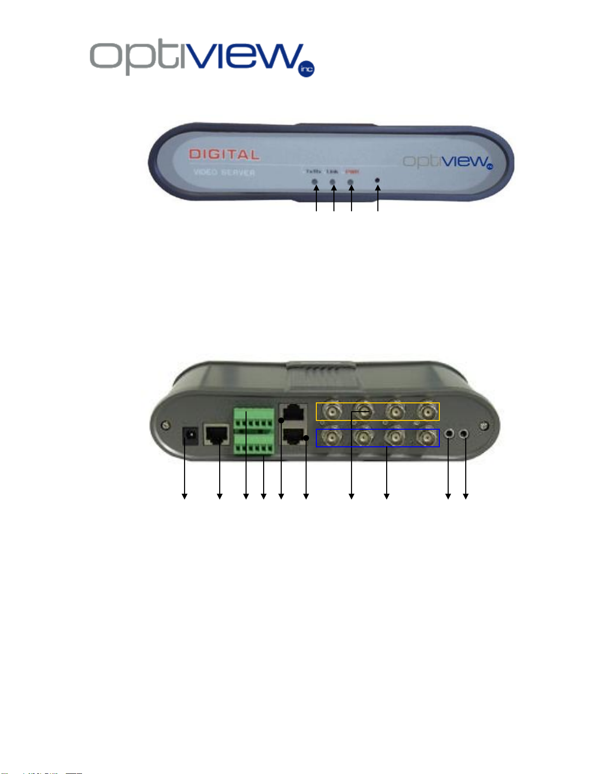
1. Front Panel
1 2 3 4
1.1 TX/RX LED indicator – indicates transmit/receive signals
1.2 Link Led indicator – indicates Ethernet link/connection with the network
1.3 PWR indicator – indicates power ON/OFF
1.4 Reset switch – clears the network information such as IP, Gateway
etc…(available only on older models)
2. Back Panel
1 2 3 4 5 6 7 8 9 10
2.1. Power Supply input – 5 or 12 Volts DC input (depending on model)
2.2. UTP – Ethernet port for the network connection
2.3. Data OUT – alarm or sensor signal output port
2.4. Data IN – alarm or sensor signal input port
2.5. RS485 – RS485 communication signal port (Use orange and
orange/white from a CAT5 cable for PTZ cameras)
2.6. RS232 – RS232 communication signal port. Also used to configure IP
information for the device
2.7. Video IN – video input port
2.8. Audio IN – audio input port, one per video input channel
2.9. LINE IN – optional audio input
2.10. LINE OUT – optional audio output
- 2 -
Page 4
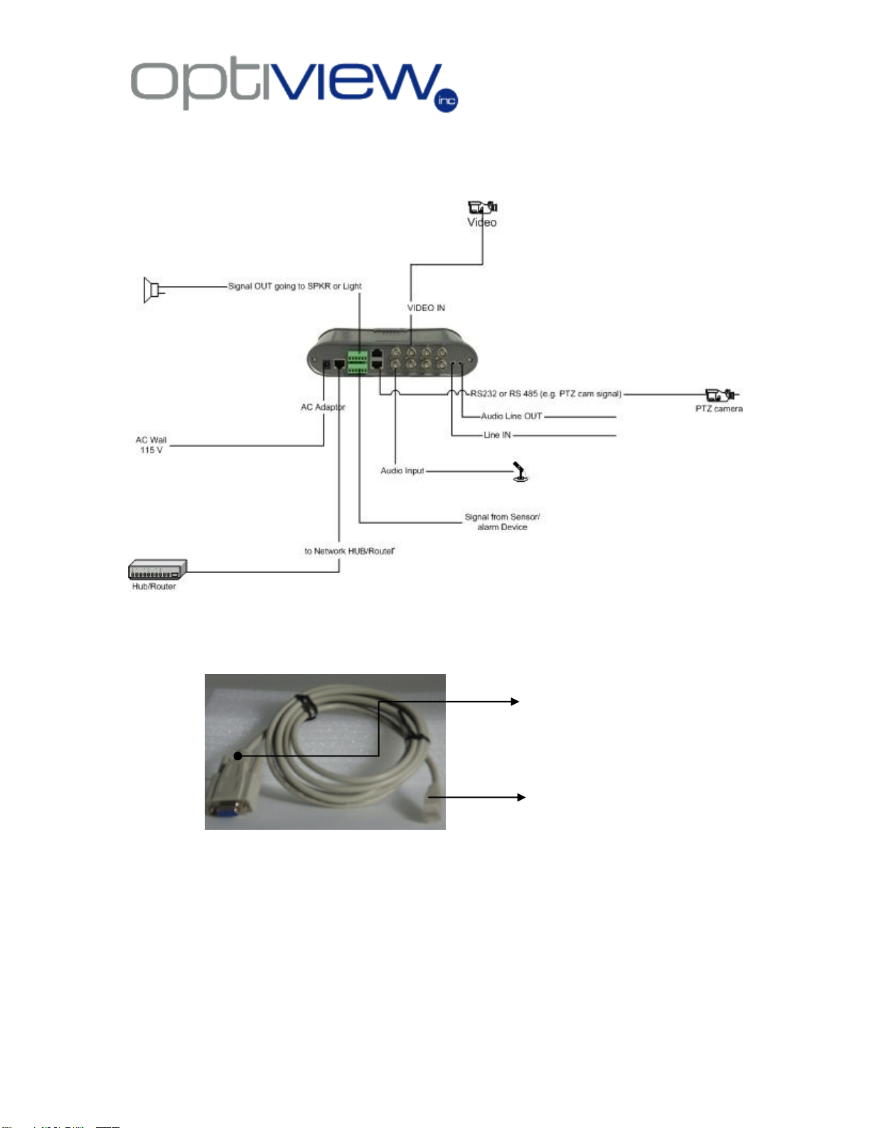
II. Installation of the Device
DB9 Connector to go to PC Serial Port
RJ45 connector to go to RS232
port of the Video Server
1. Simple Block Diagram of the Digital Video Server
2. Configuring IP Settings through the Hyper-terminal connection
2.1 Connect the RJ45-to-DB9 connector to the Video Server.
The DB9 goes into the Serial port COM1 on a PC, while the RJ45 connector goes into
the RS232 port on the DVS (Digital Video Server). Com port may not always be COM1
on a PC. Please check with your local PC configuration for correct selection of COM
port.
2.2 Turn ON the Video Server, and press the Reset Switch at the front panel. Turn
OFF/ON the DVS again. Skip this step if your unit does not have a reset switch.
- 3 -
Page 5
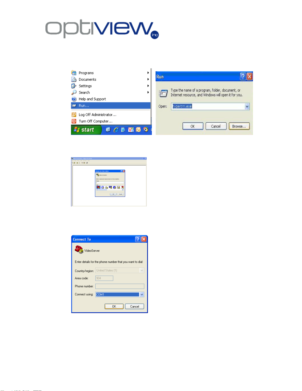
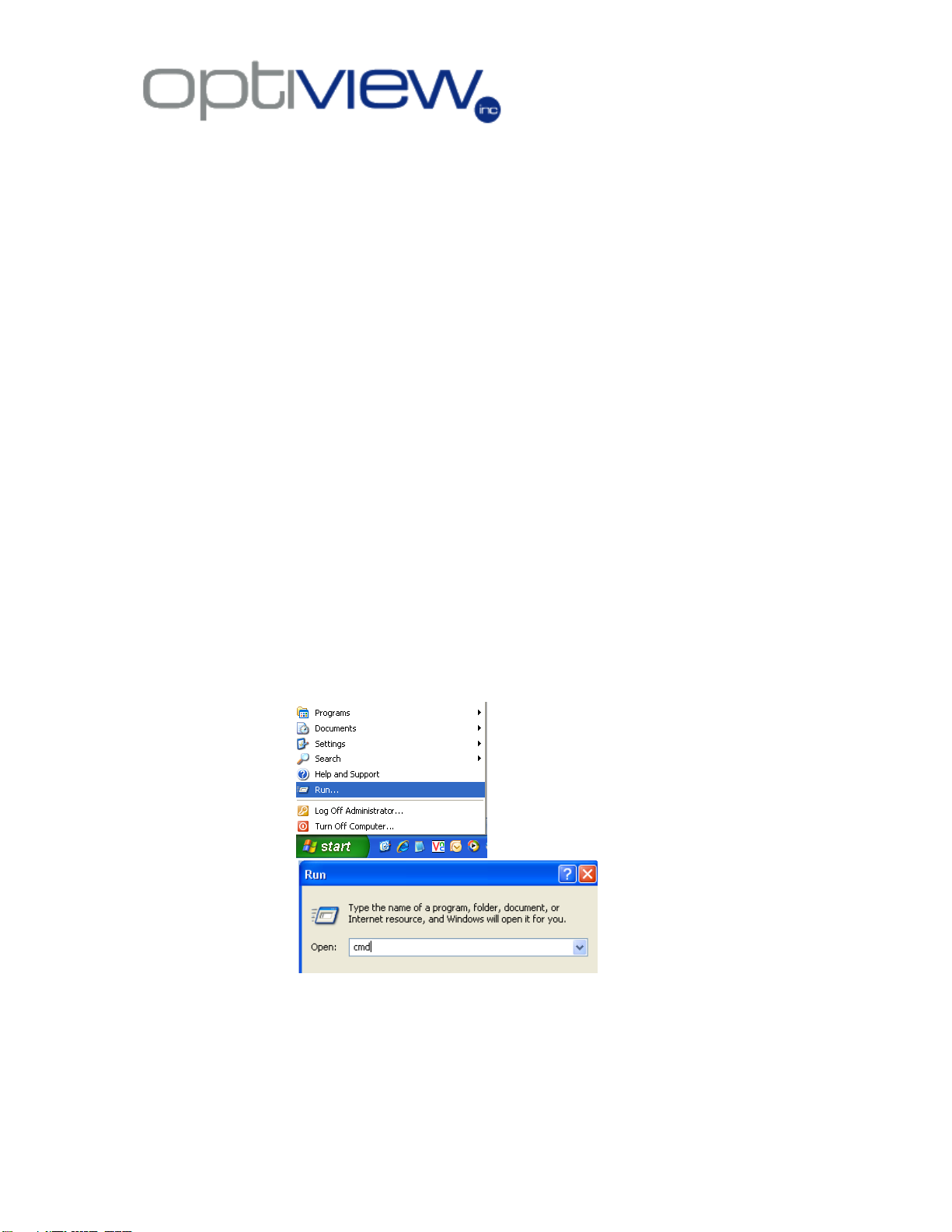
2.3 On the PC, open the Hyper-terminal program. Click on Start, RUN and then type in
hypertrm.exe Click OK.
2.4 Enter any name for the connection, such as ―VideoServer‖ and click OK.
2.5 Select the COM port to be used for the connection. Every PC has different COM
port number assigned to their serial port. Please check your local PC configuration or
consult your local PC manual.
2.6 Configure the settings; set the settings as shown below:
- 4 -
Page 6
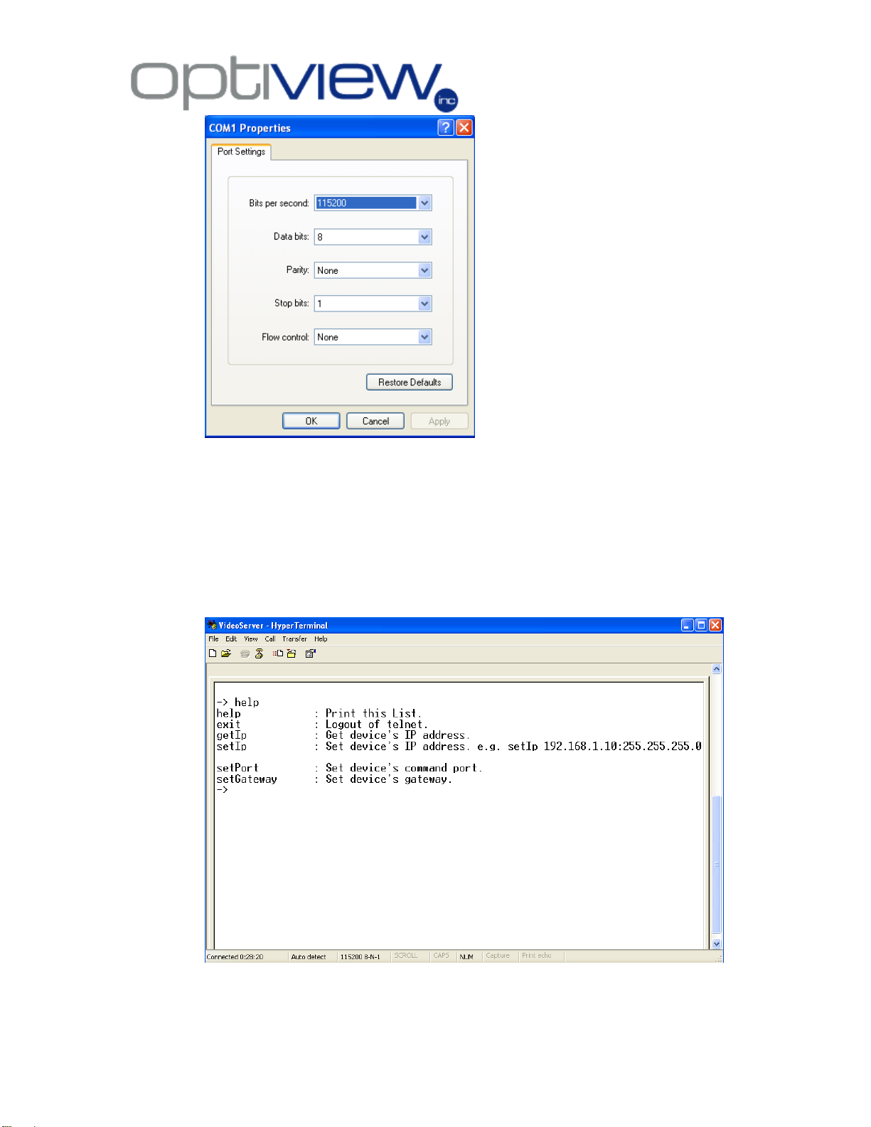
Click OK when done.
2.7 Setting the IP Information - Press Enter on the keyboard, there will be a or #
sign appearing on the screen. Type in the word help, and then press enter. This will
provide you a list of command you can use setting up the network settings on the
server. See below for the list of commands to follow on this task:
Note: The commands are caps sensitive; follow exactly how it appears on this example.
- 5 -
Page 7
2.8 Set IP Information on the DVS
Values shown here is only an example. Follow the IP address scheme on your own
Local Area Network (LAN). Consult your local IT staff or your Internet Service Provider
as to what IP address information you are going to use on this task.
To Set IP Address, Subnet Mask, Default Gateway and Port
setIp 192.168.1.200:255.255.255.0
setGateway 192.168.1.1
setPort 5000
exit
Close the Hyper-terminal program and restart the Video server after the settings has
been set up.
3. Configure the IP Video Server through Remote Client Software
3.1 You can use these default IP settings as a starting point to connect them to your
local PC and reset these IP settings by using Remote Client software to change IP
information that will work for your own local network.
1.1.1 Change the IP information of your local PC used to configure the Wireless
IP kit. Your PC IP address should be within the same range as that of the
Wireless IP Kit. You local PC must be connected to the same router/hub
where the Wireless IP kit is also connected.
1.1.2 Make sure you have excellent network connectivity between the local PC
and the Wireless IP Kit. On your local PC,
Step1
step 2
Step 3: Type the command ping followed by IP address of the IP video server.
(Note: The IP address shown here is an example only and may or may not be your
actual IP address).
- 6 -
Page 8
1.2 Use the remote client software of the Video Server to connect to the Video
server. Once connected, you will be able to have the option to make changes to
the IP settings of the Video Server. Please refer to the Remote Client Manual for
details.
4. Configure the IP Video Server through WinCap Software
4.1 Using WinPcap Software: the software will search the VR Enterprise IP video
servers/cameras, whether the IP address of the IP Video server/camera is within
or outside the IP address range of the existing network.
4.1.1 Install the WinPcap software on your local PC. (The software is only
supported by Windows 2000 and XP).
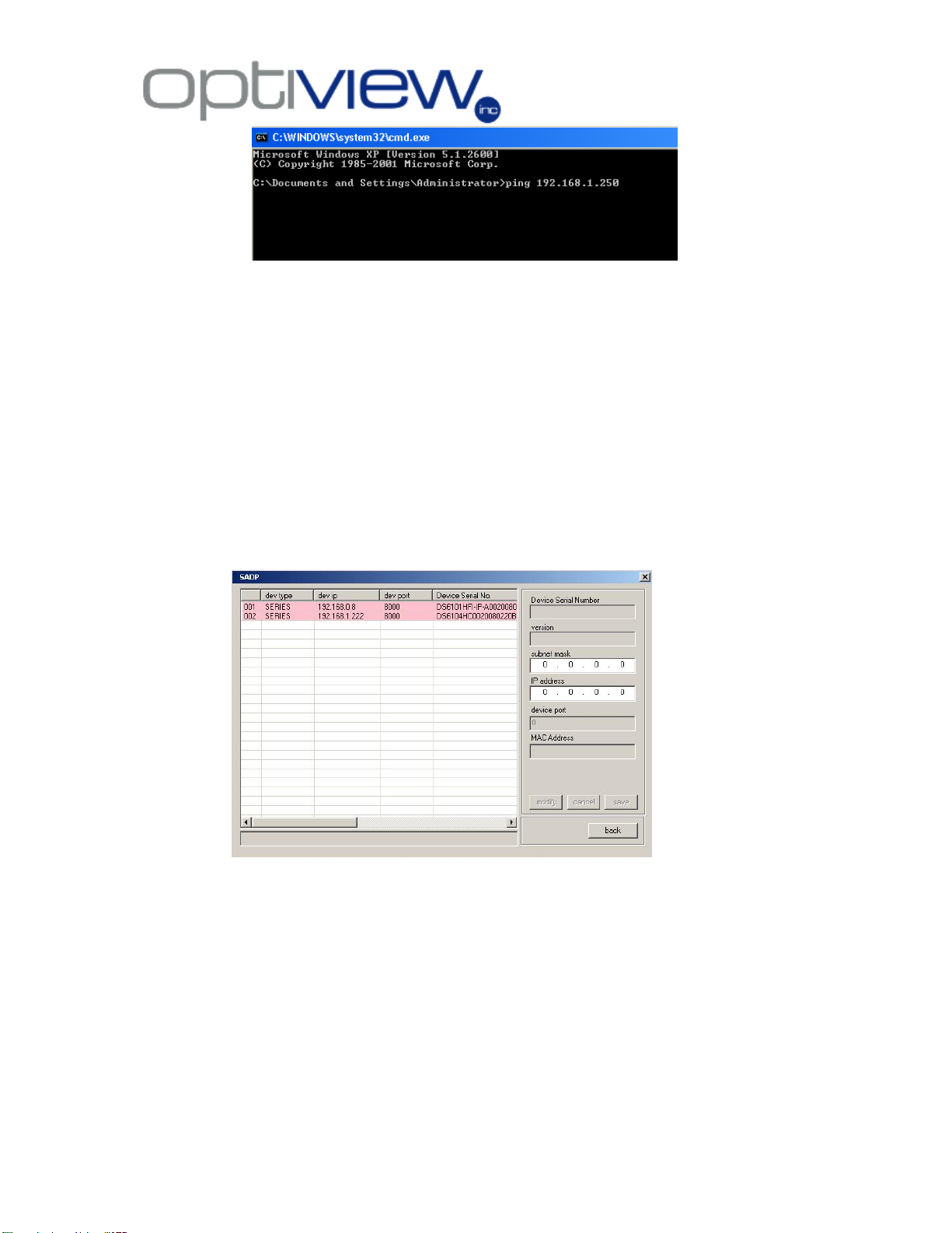
4.1.2 From the same unzipped folder, double click on sadpdlg.exe, press
“Enter” to run the IP camera search application.
4.2
Software interface will show all the IP cameras/servers found on your network. In
order to change the IP settings of a unit, highlight the server/camera using your
mouse.
- 7 -
Page 9
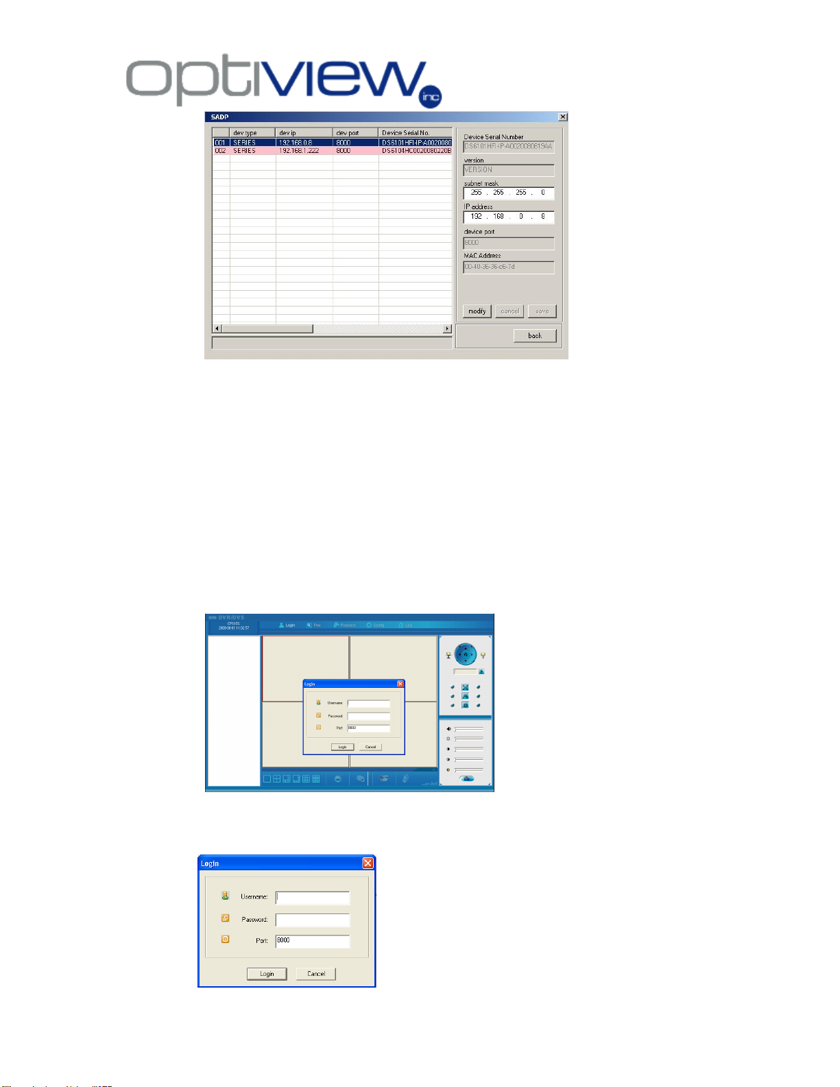
Default login name: admin
Password: 12345
Default port: 8000
4.3
IP address and subnet mask information will now be active in the text box and
ready for editing. Change these two IP information (IP address and Subnet Mask)
based on your local network setup. Please consult your local IT staff or Internet
Service Provider as to what IP address information you are going to use for your
IP video server/camera.
5. Remote Connection to Digital Video Server via Internet Explorer
5.1 Connecting to the DVR via Web browser, Internet Explorer*
Once the IP information has been setup on the Video Server and the unit is physically
connected to the network. Open the IE on a PC and type in the local IP address on the
browser’s address box to remotely connect to the video server. A local IP address
usually starts like 192.168.1.xxx or 10.0.0.xxxx.
* Note that this section (4.1) is only applicable locally, meaning accessing your DVR
within your local area network.
- 8 -
Page 10
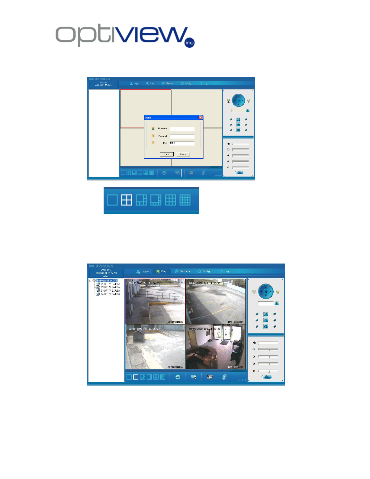
Select and double click a camera channel number to connect to it remotely. Double click the
top Server name to connect to all cameras from the Video Server. A camera number can be
displayed on any one of the screen display partition. Simply select a partition from the display
screen and double click a camera from this channel connector to connect to the camera. To
disconnect a currently connected camera, double click on the channel number in order to
disconnect.
5.2 Functionalities of the Web User Interface:
5.2.a. - Select the number of display partition you
prefer, from single screen up to 16-partition screen display. Using a mouse, point and
click to one of the display partition to select a window screen. A currently selected
display partition has a green color square around it. You will then go to Channel
Selector as shown below to double click a camera number to connect to it and have it
displayed on the window you’ve just selected.
5.2.b. Channel Connector
5.2.c PTZ Camera Control Board - remotely controls the connected PTZ camera
- 9 -
Page 11
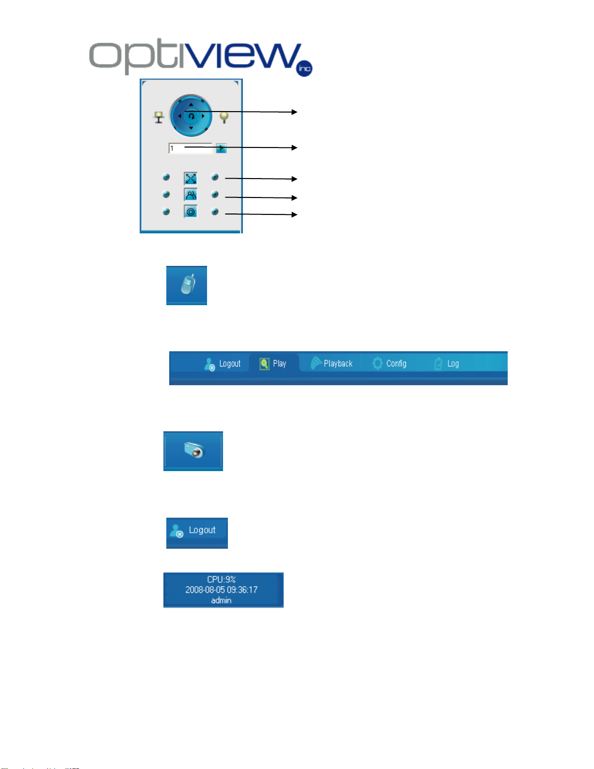
Controls the up, down , left and right
movement of the PTZ camera
Sets the movement speed of the camera
Zooms in/out on a subject
Adjust the focus
Adjust the Iris
5.2.d. - An option to have a voice chat with the other remote user. Speakers
and microphone must be provided and connected to the Digital Video Server and the
local PC.
5.2.e.
Config- Remotely configures the system settings of the Digital Video Server. The
graphical user interface (GUI) for the ―Config‖ is shown below:
5.2.f Capturing Image – captures image on currently highlighted camera
window. Use your mouse to left click on a camera window, and then click on this icon to
capture the snapshot of the image you are viewing. The directory of the snapshot file
will be given to you on a prompt window.
5.2.g. Logout – logs a user out of the Video Server.
5.2.i. Information box – generally gives your local CPU
usage rate depending on how many cameras are remotely connected and the user
account in use.
- 10 -
Page 12

6. Server Parameter Setup Menu
The common settings configured on the Video server’s Server Parameters are the
following:
5.1 Unit Name – enter a unique name to your Video server (this option is not a required
field)
5.2 IP address of the DVS – Enter the IP address of the DVS according to your own
local network settings.
5.3 Port number – This the port number used to communicate to the Remote client PC.
5.4 Subnet mask – Enter the subnet mask according to your own local network
settings.
5.5 NIC Type – the 10M/100M Auto is recommended.
- 11 -
Page 13

5.6 Gateway IP address - Enter the Gateway IP address according to your own local
network settings.
5.7 HTTP Port – Enter the port number to be used when accessing the DVR via a web
browser. The default is port 80 for HTTP, but it may differ according to your own
local network settings.
5.8 DNS IP – this IP address can be taken from the ISP
6. Channel Parameter Setup Menu
6.1 select the channel number you would like to
work on.
- 12 -
Page 14

6.2 You can name each camera with your own
descriptive name.
6.3
The settings on Major stream will affect how the video itself is processed and sent by
the Video Server, such as the image quality output which will also affect how many
days will be stored on your hard drive (remotely). Set the stream type to Video only if
there is no audio recording in order to save HDD space and lower the files size sent to
the network.
6.4
These settings affects how the video file is send through the network either LAN or
WAN. Minor stream has a low quality video resolution.
6.5
- 13 -
Page 15

Motion Detection – check this option to setup the video server’s motion detection
feature. Click on ―Area Setup‖ button to set an area for motion detection and adjust
the motion sensitivity.
6.5.1 To Send video from the IP server/camera to the main DVR Server
From the Main DVR server, to where the IP server is linked:
1. Right click over the IP server window and click on IP Camera Setup
2. Click on CHANNEL tab
3. Go to Record Schedule sub-menu to select the recording schedule, enable
recording, Days to record, ―All Day‖ or per selected time period, when to recordrecord type (is it on timing record-based on time period, motion detect, motion
detect/alarm etc…)
4. Click on Save
5. Click on Alarm Setup tab.
6. Select Camera number, select Alarm type: Motion detect
7. Click on Level: select 3
8. Click on Whole
9. On Policy, click on Upload to Center
10. Check Trigger Camera Record
7. COM/Serial Parameters Setup Menu
RS485- Used for configuring the settings when using a PTZ camera with the Video
Server. Check your actual PTZ camera dip switch settings and copy them over to this
menu.
- 14 -
Page 16

Physical Wiring Interface: Socket Pin definition
1.2.1 Standard RS232 port - RJ-45 socket pin definition
Video server has a RS232 standard port, adopt 1-45 socket definition of each pin is below, I
means video server input, O means video server output.。
(1) When video server’s port is connected with DTE/DCE equipment, one side of the cable is
RJ45 socket the other side is DB25 style socket. 25 cores bore style socket. The way to
connect 25 cores bore style socket with RJ45 is below:
(2)
picture2.2 the connection with RJ45 and DB25(DTE)
- 15 -
Page 17

(3) To connect 25 cores bore style socket with 9 cores bore style socket conversion is below:
picture2.3 the connection with DB25 and DB9
(3.1)the cable connect video server with DTE( terminal) equipment
One side of the cable is 8 cores RJ45 socket, the other side is DB9 core style
socket.
picture 2.4 the connection with RJ45 and DB9
(4) When connect video server’s port with DCE( MODEM) equipment, one side of the cable is
8 cores RJ45 socket, the other side is DB25 needle style socket. the connection with 25
cores bore socket and RJ45 is below:
- 16 -
Page 18

EIA/TIA 568B
WIRING STANDARD
PIN
Wire Color*
1
White w/Orange Stripe
2
Orange w/White Stripe
3
White w/Green Stripe
4
Blue w/White Stripe
5
White w/Blue Stripe
6
Green w/White Stripe
7
White w/Brown Stripe
8
Brown w/White Stripe
For Cross Over Cable Wiring
Wire ONE End using 568B and one end as 568A (Swap
Orange and Green Pairs)
Picture 2.5 the connection with RJ45 and DB25( DCE)
Definition of RS485 port - RJ-45 socket pin.
To use CAT5 cable for PTZ control, cut one end of a standard CAT5 network cable and use the
orange and orange/white for the RS485 data connection of the PTZ camera. Other end of the RJ45
connector pin should plugged in to the RS485 port of the Video Server.
- 17 -
Page 19

Step 1:
Remove the CAT5 from the IP
video server and insert the RJ45
coupler
Connect a network cable from your
PC (If using a cross over cable,
otherwise it will be a network cable
from a hub/switch) into this RJ45
coupler in order to access the Web
interface of the router’s
configuration menu.
Configuring the Wireless Access Point/Bridge
The Wireless IP Kit has a summary sheet enclosed inside the box for the default IP
settings of the Video Server and Wireless Access point. There are two ways to configure
or make changes to the IP settings of these two devices. First, use the default IP
information; second, make changes of IP settings to these two devices by making direct
connections to both devices.
A. Configuring the IP Address of Wireless Access Point/Bridge
1. Introduction
The Outdoor Wireless Bridge/Client Router/AP/Repeater operates seamlessly in the
2.4 GHz frequency spectrum supporting the 802.11b (2.4GHz, 11Mbps) and faster
802.11g (2.4GHz, 54Mbps) wireless standards. It's the best way to add wireless capability to your
existing wired network, or to add bandwidth to your wireless installation. EOC-3220 Series Wireless
Access Point/Bridge has high transmitted output power and high receivable sensitivity. High output
power and high sensitivity can extend range and coverage to reduce the roaming between APs to
get more stability in wireless connection. It also can reduce the expense of equipment in the same
environment. To protect your wireless connectivity, it can encrypt all wireless transmissions through
64/128-bit WEP data encryption and also supports WPA/WPA2. The MAC address filter lets you
select exactly which stations should have access to your network.
1.1 Initial Wiring Setup to Configure Wireless Access Point/Bridge
- 18 -
Page 20

Use these ports for video
cables
POE port for the Wireless
Antenna
AC cable outlet
Step 2: Connect the Wireless Antenna Ethernet cable to the POE port of the Wireless
Kit box. Plug in the main AC cable to your AC wall outlet to power up the whole
system.
1.2 Ethernet cable water proof kit Install Guide
- 19 -
Page 21

1.3 Mounting Install Guide
A. Pole Mounting
B. Wall Mounting
- 20 -
Page 22

2. Understanding the Hardware and Configuration
2.1 The figure below shows the simple block diagram how the whole Wireless IP Video Server
Kit is wired and setup.
- 21 -
Page 23

2.2 IP Address Configuration
This device can be configured as a Bridge or Access Point. The default IP address
of the device is 192.168.1.1. By default, we will set the Wireless A/P to use Bridge
Mode for this DVR application. In order to log into this device, you must first
configure the TCP/IP settings of your PC/Notebook.
- 22 -
Page 24

- 23 -
Page 25

3. Choosing the Operation Mode
This device can be configured as a Bridge or Access Point. The default IP address
of the device is 192.168.1.1 in Bridge mode. This will describe the steps to
switch from Access Point to Bridge.
The customer can always change these entire configurations in order to suit their
own local network setup. All the settings and examples shown here are for initial
setup only and must not be assumed to be the final and actual settings in order for
the device to work. Please consult your own local network staff for network setup
details. Optiview does not provide detailed technical support to configure your own
local/private network.
4. Wireless Access Point/Bridge Router Mode: Web configuration
- 24 -
Page 26

After logging in you will see the graphical user interface (GUI) of the bridge. The navigation
drop-down menu on left is divided into three main sections:
The Bridge status page is also displayed once you have logged in. This includes
details about the system, wireless, and TCP/IP configuration.
- 25 -
Page 27

4.2 Management - Click on the Management link on the navigation drop-down menu. You
will then see five options: operation mode, status, statistics, log, upgrade firmware,
save/reload settings, and password.
Each option is described below.
- 26 -
Page 28

Click on the Password link under the Management menu.
This option allows you to
create a user name and password for the device. By default,
this device is configured
without a user name and password. For security reasons it is
highly recommended
that you create a user name and password.
4.2.1 Selecting Operation Mode – for DVR applications, we will be using Bridge
mode. However, your own IT staff will still have the final word as to what mode you
will select on this menu depending on your private/local network setup.
Select the AP, Bridge or Bridge Router and then click on the Apply Change
button.
4.2.2 Setup Router’s Password
- 27 -
Page 29

4.3 TCP/IP Settings
4.3.1 LAN Interface
Click on the LAN Interface link under the TCP/IP Settings menu. Using this option
you may change the IP address of the device as well as toggle the DHCP setting.
- 28 -
Page 30

4.4 Wireless
Click on the Wireless link on the navigation
drop-down menu. You will then see four options:
basic settings, advanced settings security and
site survey. Each option is described below.
4.4.1 Basic Settings (Infrastructure, Ad-Hoc)
Click on the Basic Settings link under the Wireless menu. Using this option you
may configure the 802.11b/g settings as well as the frequency, channel, and SSID.
- 29 -
Page 31

4.5 Site Survey
Click on the Site Survey link under the Wireless menu. This page displays the list
of Access Points in the coverage area and allows you to connect to them if you
have the required credentials.
The site survey table lists the following:
o SSID: This is the unique name of the wireless network.
o BSSID: This is the MAC address of the Access Point.
o Channel: This indicates the current channel that the Access Point is
operating on, along with the 802.11 network type (B, G, or B + G).
o Encrypt: This indicates the encryption type.
o Signal: This indicates the signal strength of the Access Point.
You may select the radio button of a specific Access Point and then click on the
Connect button. If the credentials of this device match that of the Access Point
then you will be connected immediately, if not, you must specify the appropriate
credentials.
You may click on the Refresh button at any time to re-scan the area.
- 30 -
Page 32

Technical Specifications
Details
Data Rates
1, 2, 5.5, 6, 9, 11, 12, 18, 24, 36, 48, 54 Mbps
Standards
IEEE802.11b/g, IEEE802.1x, IEEE802.3, IEEE802.3u
Compatibility
IEEE 802.11g/ IEEE 802.11b
Power Requirements
Active Ethernet (802.3af) – 48 VDC/0.35Amps.
Regulation Certifications
FCC Part 15, ETSI 300/328/CE
RF Information
Frequency Band
2.400•2.4835 GHz (US, EU)
Media Access Protocol
Carrier Sense Multiple Access with Collision Avoidance (CSMA/CA)
Modulation Technology
Orthogonal Frequency Division
Multiplexing (OFDM)
DBPSK @ 1Mbps
DQPSK @2Mbps
CCK @ 5.5 & 11Mbps
BPSK @ 6 and 9 Mbps
QPSK @ 12 and 18 Mbps
16-QAM @ 24 and 36 Mbps
64-QAM @ 48 and 54 Mbps
Receive Sensitivity (Typical)
88dBm @ 6Mbps
70dBm @ 54Mbps
Available transmit power
Up to 26dBm @ 1~24Mbps
23dBm @ 36Mbps
21dBm @ 48Mbps
20dBm @ 54Mbps
Antenna
Option A: 9dBi Internal(Patch)
Option B: 5dBi External (Dipole)
Option C: 16dBi Built-in (Patch)
RF Connector
SMA (Fr) Type (Optional for External Antenna use)
Networking
Topology
Ad-Hoc, Infrastructure
Operation Mode
Point-to-Point/ Point-to-Multipoint Bridge/Client Router/ AP/ WDS/ Repeater
Interface
. Wireless IEEE802.11b/g
. One 10/100 RJ-45 port
. RS232 connector
Security
. IEEE802.1x Authenticator / RADIUS Client (EAP-MD5/TLS/TTLS) Support in
AP Mode
. WPA /WPA2
. MAC address filtering
. Hide SSID in beacons
. User isolation
. NAT in CR mode
IP Auto-configuration
DHCP client/server
Management
Configuration Interface
. Web-based configuration (HTTP)
. SNMP V1, V2c
. Telnet
Firmware Upgrade
Upgrade firmware via web-browser
Physical
Dimensions
163.8(L)mm * 135.2(W)mm * 47.0(H)mm
Weight
1.2 Kg (2.6 lbs)
Temperature Range
Operating: 0°C to 60°C (32°F to 140°F) Storage: -20°Cto 80°C (-4°F to 176°F)
Humidity (non-condensing)
5%~95% Typical
Features and Technical Specifications: Outdoor Access Point/Client Bridge
and IP Video Server
Technical Specifications: Outdoor Access Point/Client Bridge
- 31 -
Page 33

Features
Benefits
High Speed Data Rate Up to 54Mbps
Capable of handling heavy data payloads
such as MPEG video streaming
High Output Power EIRP up to 35 dBm
(with 9 dBi Patch Antenna)
Excellent output power spreads the operation
Distance. Using 5dBi antenna will provide a good wireless
connection up to 965 feet on clear view environment.
IEEE 802.11b/g Compliant
Fully Interoperable with IEEE
802.11b/IEEE802.11g compliant devices/
Watertight and Weatherproof
Avoid water invaded and weather corroded
for outdoor environment.
SNMP Remote Configuration
Management
Help administrators to remotely configure or manage the Access
Point easily.
Point-to-point, Point-to-multipoint
Wireless Connectivity
Let users transfer data between two buildings or multiple
buildings
WPA2/WPA/ IEEE 802.1x support
Powerful data security
Hide SSID (AP Mode)
Avoids unallowable users sharing bandwidth,
increases efficiency of the network.
DHCP Client/ Server
Simplifies network administration
WDS (Wireless Distributed System)
Make wireless AP and Bridge mode
simultaneously as a wireless repeater
Universal Repeater
The easiest way to expand your wireless network's coverage
MAC address filtering (AP mode)
Ensures secure network connection
User isolation support (AP mode)
Protect the private network between client
users.
PPPoE function support (CR mode)
Easy to access internet via ISP service
authentication
Power-over-Ethernet (IEEE802.3af)
Flexible Access Point locations and cost
savings
Keep personal setting
Keep the latest setting when firmware
upgrade
Features and Benefits: Outdoor Access Point/Client Bridge
- 32 -
Page 34

IP Video Server Specifications
Specifications
VS-1
VS-4
Video/Audio
Input channel
1
4
Video Compression Standard
H.264
Resolution
PAL:CIF, QCIF;
NTSC: CIF, QCIF;
PAL:4CIF,DCIF,2CIF,CIF,QCIF;
NTSC:4CIF,DCIF,2CIF,CIF,QCIF;
Video Input Interface
BNC (Electrical Level: 1.0Vp-p, Resistance: 75Ω)
NTSC, PAL System Auto Recognition
Video Frame Rate
PAL: 1/16——25 Frame/Second
NTSC: 1/16——30 Frame/Second
Code Stream
Can Select Single Video Stream or Composite Stream
Video Compression Input Bit rate
32K~2M bps self-defined (8M maximum)
Audio Input interface
BNC (Linear Electrical Level, Resistance:600Ω)
Audio Output
1 Output, RCA jack
Audio Compression Standard
OggVorbis
Audio Compression Code Rate
16Kbps
Voice Audio Input (MIC)
1 Input, RCA jack
Communication interface
1 RJ45 10M/100M Self-adaptable Ethernet Interface
1 RS232 interface
1 RS 485 interface for PTZ
Alarm input
4 ports
Alarm output
2 ports
Power Supply
DC +5V or 12 V (depends on model)
Power Consumption
Less than 4.5W
Working Temperature
-10℃--+50℃
Working Humidity
10%-90%
Size
198mm*123mm*39mm
Weight
1.5 Kg /3.3 lbs.
- 33 -
Page 35

Features and Benefits of IP Video Server
Features
Benefits
Scalability
It can be used as an independent IP Video server, connecting
up to 4 analog camera and transmit the video signal through
the LAN or WAN. It can also be linked to a main Hybrid DVR
Server where the video signal is received and recorded to its
local hard drive or NAS.
Networking Capability
Network access ready, either via Local or Wide Area
Network, hard-wired or Wireless network connectivity.
Supports TCP/IP, DHCP, PPPoE and HTTP.
Leverage and Management
Allows remote management of its internal control
configurations, user accounts management, upgrades and
maintenance.
High Resolution
Supports NTSC:4CIF,DCIF,2CIF,CIF,QCIF at real-time for 1ch servers and CIF, QCIF for 4-ch Video servers.
High performance DSP hardware compression
Uses the latest H.264 video compression technology for clear
and better video quality even at full screen resolution.
PTZ Camera Support
Supports RS485 for Pan/Tilt/Zoom cameras which can be
locally or remotely controlled via IP Server software interface.
Remote Access
Allow multiple users to log in to the system via LAN/WAN
either through IE7 Web browser or remote client software.
DVR users may have their own user rights and privileges
assigned by main administrator which has the leverage for
the user’s accounts.
- 34 -
 Loading...