

Optiview Premium General 4-HDD 720P S2, Premium General 4-HDD 720P, Premium General 720P, Premium General 720P S2, Advanced 1080P User Manual
Page 1

Standalone Embedded
DVR User’s Manual
V1.7.0
Released 01/07/2016
Page 2

Standalone DVR User’s Manual
i
Table of Contents
1 FEATURES AND SPECIFICATIONS ....................................................... 1
1.1 Overview ............................................................................................................................. 1
1.2 Features .............................................................................................................................. 1
1.3 Specifications ..................................................................................................................... 2
1.3.1 Premium General 4-HDD 720P 1.5U Series ............................................................... 2
1.3.2 Premium General 4-HDD 720P(S2)1.5U Series .................................................... 7
1.3.3 Premium General 720P 2U Series ............................................................................. 11
1.3.4 Premium General 720P(S2) 2U Series ................................................................ 15
1.3.5 Advanced 1080P 1.5U Series..................................................................................... 20
1.3.6 Advanced 1080P 2U Series ........................................................................................ 24
1.3.7 Advanced 1080P 2U RAID Series .............................................................................. 29
2 OVERVIEW AND CONTROLS ............................................................... 35
2.1 Front Panel ....................................................................................................................... 35
2.1.1 1.5U Series .................................................................................................................. 35
2.1.2 2U Series ...................................................................................................................... 36
2.1.3 Premium General 4-HDD 720P(S2)1.5U Series .................................................. 39
2.1.4 Premium General 720P(S2) 2U Series ................................................................ 39
2.1.5 Advanced 1080P 2U RAID Series .............................................................................. 40
2.2 Rear Panel ........................................................................................................................ 42
2.2.1 4/8-Channel Advanced 1080P 1.5U Series ............................................................... 42
2.2.2 16-Channel Advanced 1080P 1.5U/ Premium General 4-HDD 720P 1.5U/ Premium
General 4-HDD 720P(S2)1.5U/ Premium General 720P(S2)2U Series ..................... 44
2.2.3 4/8-Channel Advanced 1080P 2U Series .................................................................. 47
2.2.4 16-Channel Advanced 1080P 2U/ Premium General 720P 2U/ Advanced 1080P 2U
RAID Series ............................................................................................................................... 50
2.3 Connection Sample .......................................................................................................... 53
2.3.1 Advanced 1080P 1.5U Series..................................................................................... 53
Page 3

Standalone DVR User’s Manual
ii
2.3.2 16-Channel Advanced 1080P 1.5U / Premium General 4-HDD 720P 1.5U/
Premium General 4-HDD 720P(S2)1.5U/ Premium General 720P(S2)2U Series ..... 53
2.3.3 4/8-Channel Advanced 1080P 2U Series .................................................................. 54
2.3.4 16-Channel Advanced 1080P 1.5U / Premium General 720P 2U/ Advanced 1080P
2U RAID Series ......................................................................................................................... 55
2.4 Remote Control ................................................................................................................ 56
2.5 Mouse Control .................................................................................................................. 58
2.6 Virtual Keyboard & Front Panel....................................................................................... 60
2.6.1 Virtual Keyboard .......................................................................................................... 60
2.6.2 Front Panel ................................................................................................................... 60
3 INSTALLATION AND CONNECTIONS .................................................. 61
3.1 Check Unpacked DVR ................................ ..................................................................... 61
3.2 About Front Panel and Real Panel ................................................................................. 61
3.3 HDD Installation ............................................................................................................... 61
3.3.1 HDD Calculation .......................................................................................................... 61
3.3.2 HDD Installation ........................................................................................................... 62
3.4 Rack Installation ............................................................................................................... 65
3.5 Connecting Power Supply ............................................................................................... 66
3.6 Connecting Video Input and Output Devices ................................................................. 66
3.6.1 Connecting Video Input ............................................................................................... 66
3.6.2 Connecting Video Output ............................................................................................ 66
3.7 Connecting Audio Input & Output, Bidirectional Audio .................................................. 67
3.7.1 Audio Input ................................................................................................................... 67
3.7.2 Audio Output ................................................................................................................ 67
Page 4

Standalone DVR User’s Manual
iii
3.8 Alarm Input and Output Connection ............................................................................... 67
3.8.1 Alarm Input and Output Details .................................................................................. 68
3.8.2 Alarm Input Port ........................................................................................................... 68
3.8.3 Alarm Output Port ........................................................................................................ 69
3.9 RS485 ............................................................................................................................... 70
3.10 Other Interfaces ................................................................................................................ 71
4 OVERVIEW OF NAVIGATION AND CONTROLS .................................. 72
4.1 Boot up and Shutdown ................................................................................................ .... 72
4.1.1 Boot up ......................................................................................................................... 72
4.1.2 Shutdown ..................................................................................................................... 72
4.1.3 Auto Resume after Power Failure .............................................................................. 72
4.1.4 Replace Button Battery ............................................................................................... 72
4.2 Change/Reset Password ................................................................................................. 72
4.2.1 Change Password ....................................................................................................... 73
4.2.2 Reset Password ........................................................................................................... 74
4.3 Startup Wizard .................................................................................................................. 75
4.4 Preview ............................................................................................................................. 78
4.4.1 Live Viewing ................................................................................................................. 78
4.5 Right-Click Menu .............................................................................................................. 82
4.5.1 Window Switch ............................................................................................................. 83
4.5.2 PIP ................................................................................................................................ 83
4.5.3 PTZ Control .................................................................................................................. 84
4.5.4 Auto Focus ................................................................................................................... 91
4.5.5 Color ............................................................................................................................. 91
4.5.6 Search ................................................................................................ .......................... 93
4.5.7 Manual Record............................................................................................................. 93
4.5.8 Alarm Output ................................................................................................................ 93
4.5.9 Remote Device ................................................................................................ ............ 93
4.5.10
Video Matrix ................................................................................................................. 93
Page 5

Standalone DVR User’s Manual
iv
4.5.11 Main menu ............................................................................................................... 93
4.6 Navigation Bar .................................................................................................................. 93
4.6.1 Main Menu.................................................................................................................... 94
4.6.2 Output Screen .............................................................................................................. 94
4.6.3 PIP ................................................................................................................................ 94
4.6.4 Favorites ....................................................................................................................... 94
4.6.5 Channel Tree ............................................................................................................... 96
4.6.6 Tour .............................................................................................................................. 97
4.6.7 PTZ ............................................................................................................................... 97
4.6.8 Color ............................................................................................................................. 97
4.6.9 Search ................................................................................................ .......................... 97
4.6.10 Alarm Status ................................................................................................ ............ 97
4.6.11 Channel Info ............................................................................................................ 97
4.6.12 Remote Device ................................ ........................................................................ 98
4.6.13 Network .................................................................................................................... 98
4.6.14 HDD Manager.......................................................................................................... 98
4.6.15 USB Manager .......................................................................................................... 98
4.7 USB Device Auto Pop-up ................................................................................................ 98
4.8 Main Menu ........................................................................................................................ 99
4.9 Operation .......................................................................................................................... 99
4.9.1 Search ................................................................................................ .......................... 99
4.9.2 Backup ........................................................................................................................ 107
4.9.3 Shut Down .................................................................................................................. 109
4.10 Information ...................................................................................................................... 109
4.10.1 System Info ............................................................................................................ 109
4.10.2 Event ...................................................................................................................... 113
4.10.3 Network .................................................................................................................. 113
4.10.4 Log ......................................................................................................................... 116
4.11 Setting ............................................................................................................................. 118
4.11.1 Camera .................................................................................................................. 118
4.11.2 Network .................................................................................................................. 134
4.11.3 Event ...................................................................................................................... 153
4.11.4 Storage .................................................................................................................. 171
4.11.5 System ................................................................................................................... 191
Page 6

Standalone DVR User’s Manual
v
5 WEB OPERATION ............................................................................... 219
5.1 Network Connection ....................................................................................................... 219
5.2 Login................................................................................................................................ 219
5.3 LAN Mode ....................................................................................................................... 221
5.4 Real-time Monitor ........................................................................................................... 223
5.5 PTZ ................................................................................................................................ .. 224
5.6 Image/Relay-out ............................................................................................................. 225
5.6.1 Image .......................................................................................................................... 225
5.6.2 Relay output ............................................................................................................... 225
5.7 WAN Login ...................................................................................................................... 226
5.8 Setup ............................................................................................................................... 227
5.8.1 Camera ....................................................................................................................... 227
5.8.2 Network ...................................................................................................................... 236
5.8.3 Event........................................................................................................................... 254
5.8.4 Storage ....................................................................................................................... 267
5.8.5 System ........................................................................................................................ 275
5.9 Information ...................................................................................................................... 292
5.9.1 Version ....................................................................................................................... 292
5.9.2 Log .............................................................................................................................. 292
5.9.3 Connection Log .......................................................................................................... 293
5.9.4 Online User ................................................................................................................ 294
5.10 Playback ......................................................................................................................... 294
5.11 Alarm ............................................................................................................................... 299
Page 7

Standalone DVR User’s Manual
vi
5.12 Log out ................................................................................................ ............................ 300
5.13 Un-install Web Control ................................................................................................... 300
OPTIVIEW VMS..................................................................................... 301
6
7 FAQ ...................................................................................................... 302
APPENDIX A COMPATIBLE BACKUP DEVICES ....................................... 310
Appendix A-1 Compatible USB list .......................................................................................... 310
Appendix A-2 Compatible SD Card list ................................................................................... 311
Appendix A-3 Compatible Portable HDD list .......................................................................... 311
Appendix A-4 Compatible USB DVD List ............................................................................... 311
Appendix A-5 Compatible SATA DVD List ................................................................ .............. 311
Appendix A-6 Compatible SATA HDD List ............................................................................. 312
APPENDIX B COMPATIBLE CD/DVD BURNER LIST ............................. 316
APPENDIX C COMPATIBLE DISPLAYER LIST ....................................... 317
APPENDIX D COMPATIBLE SWITCHER ................................................... 318
APPENDIX E COMPATIBLE WIRELESS MOUSE LIST ........................... 319
Page 8

Standalone DVR User’s Manual
vii
APPENDIX F EARTHING ................................ ......................................... 320
APPENDIX G RAID INTRODUCTION ......................................................... 326
Appendix G-1 About RAID .......................................................................................................... 326
Appendix G-2 RAID Level ........................................................................................................... 326
Appendix G-3 RAID Capacity Calculation.................................................................................. 328
Appendix G-4 RAID Usage Suggestions ................................................................................... 328
APPENDIX H RJ45-RS232 CONNECTION CABLE DEFINITION ............... 329
Page 9

Standalone DVR User’s Manual
i
Welcome
Thank you for purchasing our DVR! This user’s manual is designed to be a reference tool for
the installation and operation of your system.
Here you can find information about this series standalone DVR features and functions.
Before installation and operation please read the following safeguards and warnings carefully!
Page 10

Standalone DVR User’s Manual
ii
Important Safeguards and Warnings
1.Electrical safety
All installation and operation here should conform to your local electrical safety codes.
The product must be grounded to reduce the risk of electric shock.
We assume no liability or responsibility for all the fires or electric shock caused by improper
handling or installation.
2.Transportation security
Heavy stress, violent vibration or water splash are not allowed during transportation, storage and
installation.
3.Installation
Keep upwards. Handle with care.
Do not apply power to the DVR before completing installation.
Do not place objects on the DVR.
4.Qualified engineers needed
All the examination and repair work should be done by the qualified service engineers.
We are not liable for any problems caused by unauthorized modifications or attempted repair.
5.Environment
The DVR should be installed in a cool, dry place away from direct sunlight, inflammable, explosive
substances and etc.
6. Accessories
Be sure to use all the accessories recommended by manufacturer.
Before installation, please open the package and check all the components are included.
Contact your local retailer ASAP if something is broken in your package.
7. Lithium battery
Improper battery use may result in fire, explosion, or personal injury!
When replace the battery, please make sure you are using the same model!
RISK OF EXPLOSION IF BATTERY IS REPLACED BY AN INCORRECT TYPE.
DISPOSE OF USED BATTERIES ACCORDING TO THE INSTRUCTIONS.
Caution
FOR YOUR DEVICE SAFETY, PLEASE CHANGE SYSTEM DEFAULT PASSWORD AFTER
YOU FIRST LOGIN IN!
Page 11

Standalone DVR User’s Manual
1
1 FEATURES AND SPECIFICATIONS
1.1 Overview
The standalone series DVR is an excellent digital monitor product designed for security
field.
It adopts embedded Linux OS to maintain reliable operation. Popular H.264 compression
algorithm and G.711 audio compression technology realize high quality, low bit stream.
Unique frame by frame play function is suitable for detailed analysis. It has various
functions such as record, playback, monitor at the same time and can guarantee audio
video synchronization. This series product has advanced technology and strong network
data transmission function.
This series device adopts embedded design to achieve high security and reliability. It can
work in the local end, and at the same time, when connecting it to the professional
surveillance software (PSS), it can connect to the security network to realize strong
network and remote monitor function.
This series product can be widely used in various areas such as banking,
telecommunication, electric power, interrogation, transportation, intelligent resident zone,
factory, warehouse, resources, and water conservancy.
1.2 Features
This series product has the following features:
Real-time surveillance
Support VGA port and HDMI port. Realize the surveillance through displayer. Support
HDMI, VGA, and TV output at the same time.
Storage function
Special data format to guarantee data security and can remove the risk of the vicious data
modification. Support digital watermark.
Compression format
Support multiple-channel audio and video. An independent hardware decodes the audio
and video signal from each channel to maintain video and audio synchronization.
Backup function
Support backup operation via USB port (such as U disk, portable HDD, burner)
Client-end user can download the file to local HDD to backup via network.
Record & playback function
Page 12

Standalone DVR User’s Manual
2
Parameter
24-Channel Series
32-Channel Series
System
Main Processor
High-performance industrial embedded micro controller
OS
Embedded LINUX
Support each channel real-time record independently, and at the same time it can support
search, forward play, network monitor, record search, download and etc.
Support various playback modes: slow play, fast play, backward play and frame by frame
play.
Support time title overlay so that you can view event accurate occurred time
Support customized zoom function during the preview.
Network operation
Support network remote real-time monitor, remote record search and remote PTZ control.
Alarm activation function
Several relay alarm outputs to realize alarm activation and on-site light control.
The alarm input port and output has the protection circuit to guarantee device safety.
Communication port
RS485 port can realize alarm input and PTZ control.
RS232 port can connect to keyboard to realize central control, and can also connect to PC
COM to upgrade system and realize maintenance, and matrix control.
Standard Ethernet port can realize network access function.
The dual-network port has the multiple-access, fault-tolerance, load-balance setup mode.
Use coaxial cable to realize camera setup and PTZ control function.
PTZ control
Support PTZ decoder via RS485.
Intelligent operation
Mouse operation function
In the menu, support copy and paste setup function
UPNP (Universal Plug and Play)
Establish mapping connection between LAN and WAN via UPNP protocol.
Camera self-adaptive
Camera PAL/NTSC and HD self-adaptive function.
Slight function differences may be found due to different series.
1.3 Specifications
1.3.1 Premium General 4-HDD 720P 1.5U Series
Page 13

Standalone DVR User’s Manual
3
System
Resources
Multiplex operations: Multiple-channel record, multiple-channel
playback and network operation simultaneously
Interface
User-friendly graphical user interface
Input Devices
USB mouse
Input Method
Arabic number, English character, donation and extension Chinese
(optional)
Shortcut
Function
Copy/paste operation, USB mouse right-key shortcut menu, double
click USB mouse to switch screen.
Compression
Standard
Video
Compression
H.264
Audio
Compression
G711A, G711U, PCM
Video monitor
Video Input
24-CH composite video input:
(NTSC/PAL) BNC (1.0VBP- P,
B75Ω)
32-CH composite video input:
(NTSC/PAL) BNC (1.0VBP- P,
B75Ω)
IP Channel
The default setup is 0.
System supports add IP
channel function.
After you disabled one
analog channel, you can add
one IP channel. System max
supports 32 IP channels.
The connection bandwidth is
160Mbps when there are
some IP channels.
The connection bandwidth is
250Mbps when there are all
IP channels.
The default setup is 0.
After you disabled one
analog channel, you can add
one IP channel. System max
supports 32 IP channels.
The connection bandwidth is
160Mbps when there are
some IP channels.
The connection bandwidth is
250Mbps when there are all
IP channels.
Video Output
1-ch PAL/NTSC, BNC (1.0VP- P, 75Ω) composite video signal output.
1-ch VGA output.
2-ch HDMI output. HDMI port1 has the same video source as the VGA
and TV. HDMI port2 is the HD aux output of the analog channel.
1-ch video matrix output.
Support TV/VGA/HDMI1/HDMI2 video output at the same time.
Video Standard
720P/25, 720P/30, 720P/50, 720P/60
Record Speed
Real-time Mode: PAL 1f/s to 25f/s per channel and NTSC 1f/s to 30f/s
per channel
Video Partition
1/4/8/9/16/25 windows(Optional)
1/4/8/9/16/25/36 windows
Monitor Touring
Support monitor tour functions such as alarm, motion detection, and
schedule auto control.
Resolution
(PAL/NTSC)
Real-time monitor:
720P 1280*720
Page 14

Standalone DVR User’s Manual
4
Playback:
1/16-ch: 720P 1280×720, 960H 960 × 576/960 × 480, D1
704×576/704×480, HD1 352×576/352×480,
2CIF 704×288/704×240, CIF 352×288/ 352×240, QCIF
176×144/176×120
Support dual streams: extra stream resolution D1
704×576/704×480, CIF 352×288/ 352×240, QCIF 176×144/176×120
Image Quality
6-level image quality (Adjustable)
Privacy mask
Support one privacy mask of user-defined size in full screen.
Support max 4 zones.
Image
Information
Channel information, time information and privacy mask zone.
TV Adjust
Adjust TV output zone suitable to anamorphic video.
Channel Lock
Cover secret channel with blue screen though system is encoding
normally.
Screen-lock function to prevent unauthorized user seeing secret video.
Channel
Information
Channel name, recording status, screen lock status, video loss status
and motion detection status are shown on the bottom left of display
screen.
Color
Configuration
Hue, brightness, contrast, saturation and gain setup for each channel.
Audio
Audio Input
4-ch 200-2000mv 10KΩ(BNC)
Audio Output
1-ch audio output 200-3000mv 5KΩ(BNC)
Bidirectional
Audio
1-channel MIC IN/1-channel MIC OUT. 200-3000mv 5KΩ(BNC)
Hard disk
Hard Disk
4 built-in SATA port. Support 4 HDDs.
One HDD
Capacity
Max 4T
Hard Disk
Occupation
Audio:PCM 28.8MByte/h
Video:56-900MByte/h
Record and
playback
Recording
Mode
Manual recording, motion detection recording, schedule recording and
alarm recording
Priority: Manual recording> alarm recording>motion detection
recording>schedule recording.
Storage Mode
Support channel record quota setup
Recording
Length
1 to 60 minutes single record duration (Default setup is 60 minutes)
Playback
Repeat Way
When hard disk is full, system can overwrite previous video file.
Page 15

Standalone DVR User’s Manual
5
Record Search
Various search engines such as time, type and channel.
Playback Mode
Various fast play, slow play speeds, manual frame by frame playback
and reverse play mode.
Various File
Switch Ways
Can switch to previous or next file or any file in current play list.
Can switch to file on other channel of the same time. (If there is a file)
Support file continuous play, when file is end system auto plays the
next file in the current channel
Playback Way
Support mark playback
Multi-channel
Playback
Support 1/4/8/16-channel modes
Window
Zoom
Switch between self-adaptive screen/full screen when playback
Partial
Enlargement
When in one-window full-screen playback mode, you can select any
zone to activate partial enlargement function.
Backup
function
Backup Mode
HDD backup
Support peripheral USB backup device. (Flash disk, portable disk,
USB burner and etc.)
Support external eSATA device backup
Support network download and backup
Network
Function
Network control
View monitor channel remotely.
DVR configuration through client-end and web browser
Upgrade via client or browser to realize remote maintenance.
View alarm information such as external alarm, motion detection and
video loss via client.
Support network PTZ lens control
File download backup and playback
Multiple devices share information via corresponding software such as
professional surveillance software (PSS)
Duplex transparent COM
Network alarm input and output
Zero-channel encoding
Bidirectional audio.
Motion
Detection and
Alarm
Motion
Detection
Zone setup: support 396((PAL 22×18, NTSC 22×15)) detection zones.
Various sensitivity levels.
Alarm can activate record or external alarm or screen message
prompt.
Video Loss
Alarm can activate external alarm or screen message prompt.
External Alarm
Support record activation function or activate external alarm or screen
message in specified period.
Manual Alarm
Control
Enable or disable alarm input channel
Support analog alarm signal to specific alarm output channel.
Alarm Input
16-ch alarm input(NO/NC)
Page 16

Standalone DVR User’s Manual
6
Alarm Output
6-channel relay output. (Including one controllable DC 12V output)
Alarm Relay
30VDC 2A,125VAC 1A(activation alarm)
Interface
USB Interface
3 USB 2.0 ports.
Network
connection
1 RJ45 10M/100M/1000M self-adaptable Ethernet port
RS485
1 RS485 port. PTZ control port
Support various PTZ control protocols.
RS232
1 RS232 port. Ordinary COM (Debug),keyboard connection and
transparent serial port(COM input and output via network )
RS422
1 RS422 port
System
Information
Hard Disk
Information
Display HDD current status
Data Stream
Statistics
Data stream statistics for each channel (in wave mode)
Log statistics
Backup to 1024 log files.
Support various search engines such as time and type.
Version
Display version information: channel amount, alarm input and output
amount, system version and release date.
On-line user
Display current on-line user
User
Management
User
Management
Multi-lever user management; various management modes
Integrated management for local user, serial port user and network
user.
Configurable user power.
Support user /group and its corresponding rights modification.
No limit to the user or group amount.
Password
Authentication
Password modification
Administrator can modify other user’s password.
Account lock strategy
Five times login failure in thirty minutes may result in account lock.
Upgrade
Web browser, client-end and update tool.
Analog Camera/HDCVI Camera
Connection Capability
Support HDCVI camera connection only.
Does not support analog camera connection.
Login, Logout and Shutdown
Password login protection to guarantee safety
User-friendly interface when login. Provide the following options:
Logout /shutdown/ restart.
Right authentication when shut down to make sure only those proper
people can turn off DVR
General
Parameter
Power
AC90~264V 50+2% Hz (Max 150W)
Power
Consumption
≤53W (With adapter, exclude HDD)
Page 17

Standalone DVR User’s Manual
7
Working
Temperature
-10℃-+55℃
Working
Humidity
10%-90%
Air Pressure
86kpa-106kpa
Dimension
1.5U standard industrial case. 440(W) x410(D) x70(H)mm
Weight
4.5-5.5KG (Exclude HDD)
Installation
Mode
Desktop/rack installation
Parameter
24-Channel Series
32-Channel Series
System
Main Processor
High-performance industrial embedded micro controller
OS
Embedded LINUX
System
Resources
Multiplex operations: Multiple-channel record, multiple-channel
playback and network operation simultaneously
Interface
User-friendly graphical user interface
Input Devices
USB mouse
Input Method
Arabic number, English character, donation and extension Chinese
(optional)
Shortcut
Function
Copy/paste operation, USB mouse right-key shortcut menu, double
click USB mouse to switch screen.
Compression
Standard
Video
Compression
H.264
Audio
Compression
G711A, G711U, PCM
Video monitor
Video Input
24-CH composite video input:
(NTSC/PAL) BNC (1.0VBP- P,
B75Ω)
32-CH composite video input:
(NTSC/PAL) BNC (1.0VBP- P,
B75Ω)
IP Channel
The default setup is 0.
System supports add IP
channel function.
After you disabled one
analog channel, you can add
one IP channel. System max
supports 32 IP channels.
The connection bandwidth is
160Mbps when there are
some IP channels.
The connection bandwidth is
250Mbps when there are all
IP channels.
The default setup is 0.
After you disabled one
analog channel, you can add
one IP channel. System max
supports 32 IP channels.
The connection bandwidth is
160Mbps when there are
some IP channels.
The connection bandwidth is
250Mbps when there are all
IP channels.
1.3.2 Premium General 4-HDD 720P(S2)1.5U Series
Page 18

Standalone DVR User’s Manual
8
Video Output
1-ch PAL/NTSC, BNC (1.0VP- P, 75Ω) composite video signal output.
1-ch VGA output.
2-ch HDMI output. HDMI port1 has the same video source as the VGA
and TV. HDMI port2 is the HD aux output of the analog channel.
1-ch video matrix output.
Support TV/VGA/HDMI1/HDMI2 video output at the same time.
Video Standard
720P/25, 720P/30, 720P/50, 720P/60
Record Speed
Real-time Mode: PAL 1f/s to 25f/s per channel and NTSC 1f/s to 30f/s
per channel
Video Partition
1/4/8/9/16/25 windows(Optional)
1/4/8/9/16/25/36 windows
Monitor Touring
Support monitor tour functions such as alarm, motion detection, and
schedule auto control.
Resolution
(PAL/NTSC)
Real-time monitor:
720P 1280*720
Playback:
1/16-ch: 720P 1280×720, 960H 960 × 576/960 × 480, D1
704×576/704×480, HD1 352×576/352×480,
2CIF 704×288/704×240, CIF 352×288/ 352×240, QCIF
176×144/176×120
Support dual streams: extra stream resolution D1
704×576/704×480, CIF 352×288/ 352×240, QCIF 176×144/176×120
Image Quality
6-level image quality (Adjustable)
Privacy mask
Support one privacy mask of user-defined size in full screen.
Support max 4 zones.
Image
Information
Channel information, time information and privacy mask zone.
TV Adjust
Adjust TV output zone suitable to anamorphic video.
Channel Lock
Cover secret channel with blue screen though system is encoding
normally.
Screen-lock function to prevent unauthorized user seeing secret video.
Channel
Information
Channel name, recording status, screen lock status, video loss status
and motion detection status are shown on the bottom left of display
screen.
Color
Configuration
Hue, brightness, contrast, saturation and gain setup for each channel.
Audio
Audio Input
4-ch 200-2000mv 10KΩ(BNC)
Audio Output
1-ch audio output 200-3000mv 5KΩ(BNC)
Bidirectional
Audio
1-channel MIC IN/1-channel MIC OUT. 200-3000mv 5KΩ(BNC)
Hard Disk
4 built-in SATA port. Support 4 HDDs.
Page 19

Standalone DVR User’s Manual
9
Hard disk
One HDD
Capacity
Max 4T
Hard Disk
Occupation
Audio:PCM 28.8MByte/h
Video:56-900MByte/h
Record and
playback
Recording
Mode
Manual recording, motion detection recording, schedule recording and
alarm recording
Priority: Manual recording> alarm recording>motion detection
recording>schedule recording.
Storage Mode
Support channel record quota setup
Recording
Length
1 to 60 minutes single record duration (Default setup is 60 minutes)
Playback
Repeat Way
When hard disk is full, system can overwrite previous video file.
Record Search
Various search engines such as time, type and channel.
Playback Mode
Various fast play, slow play speeds, manual frame by frame playback
and reverse play mode.
Various File
Switch Ways
Can switch to previous or next file or any file in current play list.
Can switch to file on other channel of the same time. (If there is a file)
Support file continuous play, when file is end system auto plays the
next file in the current channel
Playback Way
Support mark playback
Multi-channel
Playback
Support 1/4/8/16-channel modes
Window
Zoom
Switch between self-adaptive screen/full screen when playback
Partial
Enlargement
When in one-window full-screen playback mode, you can select any
zone to activate partial enlargement function.
Backup
function
Backup Mode
HDD backup
Support peripheral USB backup device. (Flash disk, portable disk,
USB burner and etc.)
Support external eSATA device backup
Support network download and backup
Network
Function
Network control
View monitor channel remotely.
DVR configuration through client-end and web browser
Upgrade via client or browser to realize remote maintenance.
View alarm information such as external alarm, motion detection and
video loss via client.
Support network PTZ lens control
File download backup and playback
Page 20

Standalone DVR User’s Manual
10
Multiple devices share information via corresponding software such as
professional surveillance software (PSS)
Duplex transparent COM
Network alarm input and output
Zero-channel encoding
Bidirectional audio.
Motion
Detection and
Alarm
Motion
Detection
Zone setup: support 396((PAL 22×18, NTSC 22×15)) detection zones.
Various sensitivity levels.
Alarm can activate record or external alarm or screen message
prompt.
Video Loss
Alarm can activate external alarm or screen message prompt.
External Alarm
Support record activation function or activate external alarm or screen
message in specified period.
Manual Alarm
Control
Enable or disable alarm input channel
Support analog alarm signal to specific alarm output channel.
Alarm Input
16-ch alarm input(NO/NC)
Alarm Output
6-channel relay output. (Including one controllable DC 12V output)
Alarm Relay
30VDC 2A,125VAC 1A(activation alarm)
Interface
USB Interface
3 USB 2.0 ports.
Network
connection
1 RJ45 10M/100M/1000M self-adaptable Ethernet port
RS485
1 RS485 port. PTZ control port
Support various PTZ control protocols.
RS232
1 RS232 port. Ordinary COM (Debug),keyboard connection and
transparent serial port(COM input and output via network )
RS422
1 RS422 port
System
Information
Hard Disk
Information
Display HDD current status
Data Stream
Statistics
Data stream statistics for each channel (in wave mode)
Log statistics
Backup to 1024 log files.
Support various search engines such as time and type.
Max support 500,000 logs
Version
Display version information: channel amount, alarm input and output
amount, system version and release date.
On-line user
Display current on-line user
User
Management
User
Management
Multi-lever user management; various management modes
Integrated management for local user, serial port user and network
user.
Configurable user power.
Support user /group and its corresponding rights modification.
No limit to the user or group amount.
Page 21

Standalone DVR User’s Manual
11
Password
Authentication
Password modification
Administrator can modify other user’s password.
Account lock strategy
Five times login failure in thirty minutes may result in account lock.
Upgrade
Web browser, client-end and update tool.
Analog Camera/HDCVI Camera
Connection Capability
Support analog camera/HDCVI camera connection. Self-adaptive, no
need to reboot.
Login, Logout and Shutdown
Password login protection to guarantee safety
User-friendly interface when login. Provide the following options:
Logout /shutdown/ restart.
Right authentication when shut down to make sure only those proper
people can turn off DVR
General
Parameter
Power
AC90~264V 50+2% Hz (Max 150W)
Power
Consumption
≤53W (With adapter, exclude HDD)
Working
Temperature
-10℃-+55℃
Working
Humidity
10%-90%
Air Pressure
86kpa-106kpa
Dimension
1.5U standard industrial case. 440(W) x410(D) x70(H)mm
Weight
4.5-5.5KG (Exclude HDD)
Installation
Mode
Desktop/rack installation
Parameter
24-Channel Series
32-Channel Series
System
Main Processor
High-performance industrial embedded micro controller
OS
Embedded LINUX
System
Resources
Multiplex operations: Multiple-channel record, multiple-channel
playback and network operation simultaneously
Interface
User-friendly graphical user interface
Input Devices
USB mouse
Input Method
Arabic number, English character, donation and extension Chinese
(optional)
Shortcut
Function
Copy/paste operation, USB mouse right-key shortcut menu, double
click USB mouse to switch screen.
Compression
Standard
Video
Compression
H.264
Audio
Compression
G711A, G711U, PCM
1.3.3 Premium General 720P 2U Series
Page 22

12
Video monitor
Video Input
24-CH composite video input:
(NTSC/PAL) BNC (1.0VBP- P,
B75Ω)
32-CH composite video input:
(NTSC/PAL) BNC (1.0VBP- P,
B75Ω)
IP Channel
The default setup is 0.
After you disabled one
analog channel, you can add
one IP channel. System max
supports 24 IP channels.
The connection bandwidth is
160Mbps when there are
some IP channels.
The connection bandwidth is
250Mbps when there are all
IP channels.
The default setup is 0.
After you disabled one
analog channel, you can add
one IP channel. System max
supports 32 IP channels.
The connection bandwidth is
160Mbps when there are
some IP channels.
The connection bandwidth is
250Mbps when there are all
IP channels.
Video Output
1-ch PAL/NTSC, BNC (1.0VP- P, 75Ω) composite video signal output.
1-ch VGA output.
2-ch HDMI output. HDMI port1 has the same video source as the VGA
and TV. HDMI port2 is the HD aux output of the analog channel.
1-ch video matrix output.
Support TV/VGA/HDMI1/HDMI2 video output at the same time.
Video Standard
720P/25, 720P/30, 720P/50, 720P/60
Record Speed
Real-time Mode: PAL 1f/s to 25f/s per channel and NTSC 1f/s to 30f/s
per channel
Video Partition
1/4/8/9/16/25 windows(Optional)
1/4/8/9/16/25/36
windows(Optional)
Monitor Touring
Support monitor tour functions such as alarm, motion detection, and
schedule auto control.
Resolution
(PAL/NTSC)
Real-time monitor:
720P 1280*720
Playback:
1/16-ch: 720P 1280×720, 960H 960 × 576/960 × 480,D1
704×576/704×480, HD1 352×576/352×480,
2CIF 704×288/704×240, CIF 352×288/ 352×240, QCIF
176×144/176×120
Support dual streams: extra stream resolution D1
704×576/704×480 CIF 352×288/ 352×240, QCIF
176×144/176×120
Image Quality
6-level image quality (Adjustable)
Privacy mask
Support one privacy mask of user-defined size in full screen.
Support max 4 zones.
Image
Information
Channel information, time information and privacy mask zone.
Standalone DVR User’s Manual
Page 23

Standalone DVR User’s Manual
13
TV Adjust
Adjust TV output zone suitable to anamorphic video.
Channel Lock
Cover secret channel with blue screen though system is encoding
normally.
Screen-lock function to prevent unauthorized user seeing secret video.
Channel
Information
Channel name, recording status, screen lock status, video loss status
and motion detection status are shown on the bottom left of display
screen.
Color
Configuration
Hue, brightness, contrast, saturation and gain setup for each channel.
Audio
Audio Input
16-ch 200-2000mv 10KΩ(BNC)
Audio Output
1-ch audio output 200-3000mv 5KΩ(BNC)
Bidirectional
Audio
1-channel MIC IN/1-channel MIC OUT. 200-3000mv 5KΩ(BNC)
Hard disk
Hard Disk
8 built-in SATA port. Support 8 HDDs.
One HDD
Capacity
Max 4T
Hard Disk
Occupation
Audio:PCM 28.8MByte/h
Video:56-900MByte/h
Record and
playback
Recording
Mode
Manual recording, motion detection recording, schedule recording and
alarm recording
Priority: Manual recording> alarm recording>motion detection
recording>schedule recording.
Storage Mode
Support channel record quota setup
Recording
Length
1 to 60 minutes single record duration (Default setup is 60 minutes)
Playback
Repeat Way
When hard disk is full, system can overwrite previous video file.
Record Search
Various search engines such as time, type and channel.
Playback Mode
Various fast play, slow play speeds, manual frame by frame playback
and reverse play mode.
Various File
Switch Ways
Can switch to previous or next file or any file in current play list.
Can switch to file on other channel of the same time. (If there is a file)
Support file continuous play, when file is end system auto plays the
next file in the current channel
Playback Way
Support mark playback
Multi-channel
Playback
Support 1/4/8/16-channel modes
Page 24

Standalone DVR User’s Manual
14
Window
Zoom
Switch between self-adaptive screen/full screen when playback
Partial
Enlargement
When in one-window full-screen playback mode, you can select any
zone to activate partial enlargement function.
Backup
function
Backup Mode
HDD backup
Support peripheral USB backup device. (Flash disk, portable disk,
USB burner and etc.)
Support external eSATA device backup
Support network download and backup
Network
Function
Network control
View monitor channel remotely.
DVR configuration through client-end and web browser
Upgrade via client or browser to realize remote maintenance.
View alarm information such as external alarm, motion detection and
video loss via client.
Support network PTZ lens control
File download backup and playback
Multiple devices share information via corresponding software such as
professional surveillance software (PSS)
Duplex transparent COM
Network alarm input and output
Zero-channel encoding
Bidirectional audio.
Motion
Detection and
Alarm
Motion
Detection
Zone setup: support 396((PAL 22×18, NTSC 22×15)) detection zones.
Various sensitivity levels.
Alarm can activate record or external alarm or screen message
prompt.
Video Loss
Alarm can activate external alarm or screen message prompt.
External Alarm
Support record activation function or activate external alarm or screen
message in specified period.
Manual Alarm
Control
Enable or disable alarm input channel
Support analog alarm signal to specific alarm output channel.
Alarm Input
16-ch alarm input(NO/NC)
Alarm Output
6-channel relay output. (Including one controllable DC 12V output)
Alarm Relay
30VDC 2A,125VAC 1A(activation alarm)
Interface
USB Interface
4 USB 2.0 ports.
Network
connection
2 RJ45 10M/100M/1000M self-adaptable Ethernet ports
RS485
1 RS485 port. PTZ control port
Support various PTZ control protocols.
RS232
1 RS232 port. Ordinary COM (Debug),keyboard connection and
transparent serial port(COM input and output via network )
RS422
1 RS422 port.
Page 25

Standalone DVR User’s Manual
15
System
Information
Hard Disk
Information
Display HDD current status
Data Stream
Statistics
Data stream statistics for each channel (in wave mode)
Log statistics
Backup to 1024 log files.
Support various search engines such as time and type.
Version
Display version information: channel amount, alarm input and output
amount, system version and release date.
On-line user
Display current on-line user
User
Management
User
Management
Multi-lever user management; various management modes
Integrated management for local user, serial port user and network
user.
Configurable user power.
Support user /group and its corresponding rights modification.
No limit to the user or group amount.
Password
Authentication
Password modification
Administrator can modify other user’s password.
Account lock strategy
Five times login failure in thirty minutes may result in account lock.
Upgrade
Web browser, client-end and update tool.
Analog Camera/HDCVI Camera
Connection Capability
Support HDCVI camera connection only.
Does not support analog camera.
Login, Logout and Shutdown
Password login protection to guarantee safety
User-friendly interface when login. Provide the following options:
Logout /shutdown/ restart.
Right authentication when shut down to make sure only those proper
people can turn off DVR
General
Parameter
Power
AC90~264V 50+2% Hz (Max 150W)
Power
Consumption
≤53W (With adapter, exclude HDD)
Working
Temperature
-10℃-+55℃
Working
Humidity
10%-90%
Air Pressure
86kpa-106kpa
Dimension
2U standard industrial case. 440(W) x460(D) x89(H)mm
Weight
7.0-8.0KG (Exclude HDD)
Installation
Mode
Desktop/rack installation
Parameter
24-Channel Series
32-Channel Series
1.3.4 Premium General 720P(S2) 2U Series
Page 26

Standalone DVR User’s Manual
16
System
Main Processor
High-performance industrial embedded micro controller
OS
Embedded LINUX
System
Resources
Multiplex operations: Multiple-channel record, multiple-channel
playback and network operation simultaneously
Interface
User-friendly graphical user interface
Input Devices
USB mouse
Input Method
Arabic number, English character, donation and extension Chinese
(optional)
Shortcut
Function
Copy/paste operation, USB mouse right-key shortcut menu, double
click USB mouse to switch screen.
Compression
Standard
Video
Compression
H.264
Audio
Compression
G711A, G711U, PCM
Video monitor
Video Input
24-CH composite video input:
(NTSC/PAL) BNC (1.0VBP- P,
B75Ω)
32-CH composite video input:
(NTSC/PAL) BNC (1.0VBP- P,
B75Ω)
IP Channel
The default setup is 0.
System supports add IP
channel function.
After you disabled one
analog channel, you can add
one IP channel. System max
supports 32 IP channels.
The connection bandwidth is
160Mbps when there are
some IP channels.
The connection bandwidth is
250Mbps when there are all
IP channels.
The default setup is 0.
After you disabled one
analog channel, you can add
one IP channel. System max
supports 32 IP channels.
The connection bandwidth is
160Mbps when there are
some IP channels.
The connection bandwidth is
250Mbps when there are all
IP channels.
Video Output
1-ch PAL/NTSC, BNC (1.0VP- P, 75Ω) composite video signal output.
1-ch VGA output.
2-ch HDMI output. HDMI port1 has the same video source as the VGA
and TV. HDMI port2 is the HD aux output of the analog channel.
1-ch video matrix output.
Support TV/VGA/HDMI1/HDMI2 video output at the same time.
Video Standard
720P/25, 720P/30, 720P/50, 720P/60
Record Speed
Real-time Mode: PAL 1f/s to 25f/s per channel and NTSC 1f/s to 30f/s
per channel
Video Partition
1/4/8/9/16/25 windows(Optional)
1/4/8/9/16/25/36
windows(Optional)
Page 27

Standalone DVR User’s Manual
17
Monitor Touring
Support monitor tour functions such as alarm, motion detection, and
schedule auto control.
Resolution
(PAL/NTSC)
Real-time monitor:
720P 1280*720
Playback:
1/16-ch: 720P 1280×720, 960H 960 × 576/960 × 480,D1
704×576/704×480, HD1 352×576/352×480,
2CIF 704×288/704×240, CIF 352×288/ 352×240, QCIF
176×144/176×120
Support dual streams: extra stream resolution D1
704×576/704×480 CIF 352×288/ 352×240, QCIF
176×144/176×120
Image Quality
6-level image quality (Adjustable)
Privacy mask
Support one privacy mask of user-defined size in full screen.
Support max 4 zones.
Image
Information
Channel information, time information and privacy mask zone.
TV Adjust
Adjust TV output zone suitable to anamorphic video.
Channel Lock
Cover secret channel with blue screen though system is encoding
normally.
Screen-lock function to prevent unauthorized user seeing secret video.
Channel
Information
Channel name, recording status, screen lock status, video loss status
and motion detection status are shown on the bottom left of display
screen.
Color
Configuration
Hue, brightness, contrast, saturation and gain setup for each channel.
Audio
Audio Input
16-ch 200-2000mv 10KΩ(BNC)
Audio Output
1-ch audio output 200-3000mv 5KΩ(BNC)
Bidirectional
Audio
1-channel MIC IN/1-channel MIC OUT. 200-3000mv 5KΩ(BNC)
Hard disk
Hard Disk
8 built-in SATA port. Support 8 HDDs.
One HDD
Capacity
Max 4T
Hard Disk
Occupation
Audio:PCM 28.8MByte/h
Video:56-900MByte/h
Record and
playback
Recording
Mode
Manual recording, motion detection recording, schedule recording and
alarm recording
Priority: Manual recording> alarm recording>motion detection
recording>schedule recording.
Storage Mode
Support channel record quota setup
Page 28

Standalone DVR User’s Manual
18
Recording
Length
1 to 60 minutes single record duration (Default setup is 60 minutes)
Playback
Repeat Way
When hard disk is full, system can overwrite previous video file.
Record Search
Various search engines such as time, type and channel.
Playback Mode
Various fast play, slow play speeds, manual frame by frame playback
and reverse play mode.
Various File
Switch Ways
Can switch to previous or next file or any file in current play list.
Can switch to file on other channel of the same time. (If there is a file)
Support file continuous play, when file is end system auto plays the
next file in the current channel
Playback Way
Support mark playback
Multi-channel
Playback
Support 1/4/8/16-channel modes
Window
Zoom
Switch between self-adaptive screen/full screen when playback
Partial
Enlargement
When in one-window full-screen playback mode, you can select any
zone to activate partial enlargement function.
Backup
function
Backup Mode
HDD backup
Support peripheral USB backup device. (Flash disk, portable disk,
USB burner and etc.)
Support external eSATA device backup
Support network download and backup
Network
Function
Network control
View monitor channel remotely.
DVR configuration through client-end and web browser
Upgrade via client or browser to realize remote maintenance.
View alarm information such as external alarm, motion detection and
video loss via client.
Support network PTZ lens control
File download backup and playback
Multiple devices share information via corresponding software such as
professional surveillance software (PSS)
Duplex transparent COM
Network alarm input and output
Zero-channel encoding
Bidirectional audio.
Motion
Detection and
Alarm
Motion
Detection
Zone setup: support 396((PAL 22×18, NTSC 22×15)) detection zones.
Various sensitivity levels.
Alarm can activate record or external alarm or screen message
prompt.
Video Loss
Alarm can activate external alarm or screen message prompt.
Page 29

Standalone DVR User’s Manual
19
External Alarm
Support record activation function or activate external alarm or screen
message in specified period.
Manual Alarm
Control
Enable or disable alarm input channel
Support analog alarm signal to specific alarm output channel.
Alarm Input
16-ch alarm input(NO/NC)
Alarm Output
6-channel relay output. (Including one controllable DC 12V output)
Alarm Relay
30VDC 2A,125VAC 1A(activation alarm)
Interface
USB Interface
4 USB 2.0 ports.
Network
connection
2 RJ45 10M/100M/1000M self-adaptable Ethernet ports
RS485
1 RS485 port. PTZ control port
Support various PTZ control protocols.
RS232
1 RS232 port. Ordinary COM (Debug),keyboard connection and
transparent serial port(COM input and output via network )
RS422
1 RS422 port.
System
Information
Hard Disk
Information
Display HDD current status
Data Stream
Statistics
Data stream statistics for each channel (in wave mode)
Log statistics
Backup to 1024 log files.
Support various search engines such as time and type.
Version
Display version information: channel amount, alarm input and output
amount, system version and release date.
On-line user
Display current on-line user
User
Management
User
Management
Multi-lever user management; various management modes
Integrated management for local user, serial port user and network
user.
Configurable user power.
Support user /group and its corresponding rights modification.
No limit to the user or group amount.
Password
Authentication
Password modification
Administrator can modify other user’s password.
Account lock strategy
Five times login failure in thirty minutes may result in account lock.
Upgrade
Web browser, client-end and update tool.
Analog Camera/HDCVI Camera
Connection Capability
Support analog camera/HDCVI camera connection. Self-adaptive, no
need to reboot.
Login, Logout and Shutdown
Password login protection to guarantee safety
User-friendly interface when login. Provide the following options:
Logout /shutdown/ restart.
Right authentication when shut down to make sure only those proper
people can turn off DVR
Page 30

Standalone DVR User’s Manual
20
General
Parameter
Power
AC90~264V 50+2% Hz (Max 150W)
Power
Consumption
≤53W (With adapter, exclude HDD)
Working
Temperature
-10℃-+55℃
Working
Humidity
10%-90%
Air Pressure
86kpa-106kpa
Dimension
2U standard industrial case. 440(W) x460(D) x89(H)mm
Weight
7.0-8.0KG (Exclude HDD)
Installation
Mode
Desktop/rack installation
Parameter
4-Ch Series
8-Ch Series
16-Ch Series
System
Main Processor
High-performance industrial embedded micro controller
OS
Embedded LINUX
System
Resources
Multiplex operations: Multiple-channel record, multiple-channel
playback and network operation simultaneously
Interface
User-friendly graphical user interface
Input Devices
USB mouse
Input Method
Arabic number, English character, donation and extension Chinese
(optional)
Shortcut
Function
Copy/paste operation, USB mouse right-key shortcut menu, double
click USB mouse to switch screen.
Compression
Standard
Video
Compression
H.264
Audio
Compression
G711A, G711U, PCM
Video Input
4-CH composite
video input:
(NTSC/PAL) BNC
(1.0VBP- P, B75Ω)
8-CH composite video
input: (NTSC/PAL)
BNC (1.0VBP- P,
B75Ω)
16-CH composite
video input:
(NTSC/PAL) BNC
(1.0VBP- P, B75Ω)
1.3.5 Advanced 1080P 1.5U Series
Page 31

21
Video monitor
IP Channel
The default setup is 0.
After you disabled one analog channel, you can add one IP
channel.
System supports add IP channel function. For 4 channel series
product, it max supports 8 IP channels. For 8 channel series
product, it max supports 16 IP channels. For 16 channel series
product, it max supports 32 IP channels.
The connection bandwidth is 160Mbps when there are some IP
channels.
The connection bandwidth is 250Mbps when there are all IP
channels.
Video Output
1-ch PAL/NTSC, BNC (1.0VP- P, 75Ω) composite video signal output.
1-ch VGA output.
2-ch HDMI output. HDMI port1 has the same video source as the VGA
and TV. HDMI port2 is the HD aux output of the analog channel.
1-ch video matrix output.
Support TV/VGA/HDMI1/HDMI2 video output at the same time.
Video Standard
720P/25, 720P/30, 720P/50, 720P/60, 1080P/25, 1080P/30
Record Speed
Real-time Mode: PAL 1f/s to 25f/s per channel and NTSC 1f/s to 30f/s
per channel
Video Partition
1/4 windows
1/4/8/9 windows
1/4/8/9/16 windows
Monitor Touring
Support monitor tour functions such as alarm, motion detection, and
schedule auto control.
Resolution
(PAL/NTSC)
Real-time monitor:
1080P 1920*1080
Playback:
1/16-ch: 1080P 1920*1080, 720P 1280×720, 960H 960 × 576/960
× 480,D1 704×576/704×480, HD1 352×576/352×480,
2CIF 704×288/704×240, CIF 352×288/ 352×240, QCIF
176×144/176×120
Support dual streams: extra stream resolution D1
704×576/704×480, CIF 352×288/ 352×240, QCIF
176×144/176×120
Image Quality
6-level image quality (Adjustable)
Privacy mask
Support one privacy mask of user-defined size in full screen.
Support max 4 zones.
Image
Information
Channel information, time information and privacy mask zone.
TV Adjust
Adjust TV output zone suitable to anamorphic video.
Channel Lock
Cover secret channel with blue screen though system is encoding
normally.
Screen-lock function to prevent unauthorized user seeing secret video.
Standalone DVR User’s Manual
Page 32

Standalone DVR User’s Manual
22
Channel
Information
Channel name, recording status, screen lock status, video loss status
and motion detection status are shown on the bottom left of display
screen.
Color
Configuration
Hue, brightness, contrast, saturation and gain setup for each channel.
Audio
Audio Input
4-ch 200-2000mv 10KΩ(BNC)
Audio Output
1-ch audio output 200-3000mv 5KΩ(BNC)
Bidirectional
Audio
1-channel MIC IN and 1-channel MIC OUT. 200-3000mv 5KΩ(BNC)
Hard disk
Hard Disk
4 built-in SATA port. Support 4 HDDs.
One HDD
Capacity
Max 4T
Hard Disk
Occupation
Audio:PCM 28.8MByte/h
Video:56-900MByte/h
Record and
playback
Recording
Mode
Manual recording, motion detection recording, schedule recording and
alarm recording
Priority: Manual recording> alarm recording>motion detection
recording>schedule recording.
Storage Mode
Support channel record quota setup
Recording
Length
1 to 60 minutes single record duration (Default setup is 60 minutes)
Playback
Repeat Way
When hard disk is full, system can overwrite previous video file.
Record Search
Various search engines such as time, type and channel.
Playback Mode
Various fast play, slow play speeds, manual frame by frame playback
and reverse play mode.
Various File
Switch Ways
Can switch to previous or next file or any file in current play list.
Can switch to file on other channel of the same time. (If there is a file)
Support file continuous play, when file is end system auto plays the
next file in the current channel
Playback Way
Support mark playback
Multi-channel
Playback
Support 1/4-channel
modes
Support
1/4/8-channel modes
Support
1/4/8/16-channel
modes
Window
Zoom
Switch between self-adaptive screen/full screen when playback
Partial
Enlargement
When in one-window full-screen playback mode, you can select any
zone to activate partial enlargement function.
Backup
Backup Mode
HDD backup
Page 33

Standalone DVR User’s Manual
23
function
Support peripheral USB backup device. (Flash disk, portable disk,
USB burner and etc.)
Support external eSATA device backup
Support network download and backup
Network
Function
Network control
View monitor channel remotely.
DVR configuration through client-end and web browser
Upgrade via client or browser to realize remote maintenance.
View alarm information such as external alarm, motion detection and
video loss via client.
Support network PTZ lens control
File download backup and playback
Multiple devices share information via corresponding software such as
professional surveillance software (PSS)
Duplex transparent COM
Network alarm input and output
Zero-channel encoding
Bidirectional audio.
Motion
Detection and
Alarm
Motion
Detection
Zone setup: support 396((PAL 22×18, NTSC 22×15)) detection zones.
Various sensitivity levels.
Alarm can activate record or external alarm or screen message
prompt.
Video Loss
Alarm can activate external alarm or screen message prompt.
External Alarm
Support record activation function or activate external alarm or screen
message in specified period.
Manual Alarm
Control
Enable or disable alarm input channel
Simulate alarm signal to specific alarm output channel.
Alarm Input
4-ch alarm input
(NO/NC)
8-ch alarm input(NO/NC)
16-ch alarm input
(NO/NC)
Alarm Output
6-channel relay output. (Including one controllable DC 12V output)
Alarm Relay
30VDC 2A,125VAC 1A(activation alarm )
Interface
USB Interface
3 USB 2.0 ports.
Network
connection
1 RJ45 10M/100M/1000M self-adaptable Ethernet port
RS485
1 RS485 port. PTZ control port
Support various PTZ control protocols.
RS232
1 RS232 port. Ordinary COM (Debug),keyboard connection and
transparent serial port(COM input and output via network )
RS422
1 RS422 port
System
Information
Hard Disk
Information
Display HDD current status
Data Stream
Statistics
Data stream statistics for each channel (in wave mode)
Page 34

Standalone DVR User’s Manual
24
Log statistics
Backup to 1024 log files.
Support various search engines such as time and type.
Version
Display version information: channel amount, alarm input and output
amount, system version and release date.
On-line user
Display current on-line user
User
Management
User
Management
Multi-lever user management; various management modes
Integrated management for local user, serial port user and network
user.
Configurable user power.
Support user /group and its corresponding rights modification.
No limit to the user or group amount.
Password
Authentication
Password modification
Administrator can modify other user’s password.
Account lock strategy
Five times login failure in thirty minutes may result in account lock.
Upgrade
Web browser, client-end and update tool.
Analog Camera/HDCVI Camera
Connection Capability
Support analog camera/HDCVI camera connection. Self-adaptive, no
need to reboot.
Login, Logout and Shutdown
Password login protection to guarantee safety
User-friendly interface when login. Provide the following options:
Logout /shutdown/ restart.
Right authentication when shut down to make sure only those proper
people can turn off DVR
General
Parameter
Power
AC90~264V 50+2% Hz (For 4-channel series product: max 75W. For
8-channel series product: max 75W power. For 16-channel series
product: max 150W)
Power
Consumption
≤44W (With adapter, exclude HDD)
Working
Temperature
-10℃-+55℃
Working
Humidity
10%-90%
Air Pressure
86kpa-106kpa
Dimension
1.5U standard industrial case. 440(W) x410(D) x70(H)mm
Weight
4.5-5.5KG (Exclude HDD)
Installation
Mode
Desktop/Rack installation
Parameter
4-Ch Series
8-Ch Series
16-Ch Series
Main Processor
High-performance industrial embedded micro controller
1.3.6 Advanced 1080P 2U Series
Page 35

Standalone DVR User’s Manual
25
System
OS
Embedded LINUX
System
Resources
Multiplex operations: Multiple-channel record, multiple-channel
playback and network operation simultaneously
Interface
User-friendly graphical user interface
Input Devices
USB mouse
Input Method
Arabic number, English character, donation and extension Chinese
(optional)
Shortcut
Function
Copy/paste operation, USB mouse right-key shortcut menu, double
click USB mouse to switch screen.
Compression
Standard
Video
Compression
H.264
Audio
Compression
G711A, G711U, PCM
Video monitor
Video Input
4-CH composite
video input:
(NTSC/PAL) BNC
(1.0VBP- P, B75Ω)
8-CH composite video
input: (NTSC/PAL)
BNC (1.0VBP- P,
B75Ω)
16-CH composite
video input:
(NTSC/PAL) BNC
(1.0VBP- P, B75Ω)
IP Channel
The default setup is 0.
After you disabled one analog channel, you can add one IP
channel.
System supports add IP channel function. For 4-channel series
product, it max supports 8 IP channels. For 8-channel series
product, it max supports 16 IP channels. For 16-channel series
product, it max supports 32 IP channels.
The connection bandwidth is 160Mbps when there are some IP
channels.
The connection bandwidth is 250Mbps when there are all IP
channels.
Video Output
1-ch PAL/NTSC, BNC (1.0VP- P, 75Ω) composite video signal output.
1-ch VGA output.
2-ch HDMI output. HDMI port1 has the same video source as the VGA
and TV. HDMI port2 is the HD aux output of the analog channel.
1-ch video matrix output.
Support TV/VGA/HDMI1/HDMI2 video output at the same time.
Video Standard
720P/25, 720P/30, 720P/50, 720P/60, 1080P/25, 1080P/30
Record Speed
Real-time Mode: PAL 1f/s to 25f/s per channel and NTSC 1f/s to 30f/s
per channel
Video Partition
1/4 windows
1/4/8/9 windows
1/4/8/9/16 windows
Monitor Touring
Support monitor tour functions such as alarm, motion detection, and
schedule auto control.
Resolution
(PAL/NTSC)
Real-time monitor:
1080P 1920*1080
Page 36

Standalone DVR User’s Manual
26
Playback:
1/16-ch: 1080P 1920*1080, 720P 1280×720, 960H 960 × 576/960 × 480,D1
704×576/704×480, HD1 352×576/352×480,
2CIF 704×288/704×240, CIF 352×288/ 352×240, QCIF
176×144/176×120
Support dual streams: extra stream resolution D1
704×576/704×480, CIF 352×288/ 352×240, QCIF
176×144/176×120
Image Quality
6-level image quality (Adjustable)
Privacy mask
Support one privacy mask of user-defined size in full screen.
Support max 4 zones.
Image
Information
Channel information, time information and privacy mask zone.
TV Adjust
Adjust TV output zone suitable to anamorphic video.
Channel Lock
Cover secret channel with blue screen though system is encoding
normally.
Screen-lock function to prevent unauthorized user seeing secret video.
Channel
Information
Channel name, recording status, screen lock status, video loss status
and motion detection status are shown on the bottom left of display
screen.
Color
Configuration
Hue, brightness, contrast, saturation and gain setup for each channel.
Audio
Audio Input
4-ch 200-2000mv
10KΩ(BNC)
8-ch 200-2000mv
10KΩ(BNC)
16-ch 200-2000mv
10KΩ(BNC)
Audio Output
1-ch audio output 200-3000mv 5KΩ(BNC)
Bidirectional
Audio
1-channel MIC IN and 1-channel MIC OUT. 200-3000mv 5KΩ(BNC)
Hard disk
Hard Disk
8 built-in SATA port. Support 8 HDDs.
One HDD
Capacity
Max 4T
Hard Disk
Occupation
Audio:PCM 28.8MByte/h
Video:56-900MByte/h
Record and
playback
Recording
Mode
Manual recording, motion detection recording, schedule recording and
alarm recording
Priority: Manual recording> alarm recording>motion detection
recording>schedule recording.
Storage Mode
Support channel record quota setup
Recording
Length
1 to 60 minutes single record duration (Default setup is 60 minutes)
Page 37

Standalone DVR User’s Manual
27
Playback
Repeat Way
When hard disk is full, system can overwrite previous video file.
Record Search
Various search engines such as time, type and channel.
Playback Mode
Various fast play, slow play speeds, manual frame by frame playback
and reverse play mode.
Various File
Switch Ways
Can switch to previous or next file or any file in current play list.
Can switch to file on other channel of the same time. (If there is a file)
Support file continuous play, when file is end system auto plays the
next file in the current channel
Playback Way
Support mark playback
Multi-channel
Playback
Support 1/4-channel
modes
Support
1/4/8-channel modes
Support
1/4/8/16-channel
modes
Window
Zoom
Switch between self-adaptive screen/full screen when playback
Partial
Enlargement
When in one-window full-screen playback mode, you can select any
zone to activate partial enlargement function.
Backup
function
Backup Mode
HDD backup
Support peripheral USB backup device. (Flash disk, portable disk,
USB burner and etc.)
Support external eSATA device backup
Support network download and backup
Network
Function
Network control
View monitor channel remotely.
DVR configuration through client-end and web browser
Upgrade via client or browser to realize remote maintenance.
View alarm information such as external alarm, motion detection and
video loss via client.
Support network PTZ lens control
File download backup and playback
Multiple devices share information via corresponding software such as
professional surveillance software (PSS)
Duplex transparent COM
Network alarm input and output
Zero-channel encoding
Bidirectional audio.
Motion
Detection and
Alarm
Motion
Detection
Zone setup: support 396((PAL 22×18, NTSC 22×15)) detection zones.
Various sensitivity levels.
Alarm can activate record or external alarm or screen message
prompt.
Video Loss
Alarm can activate external alarm or screen message prompt.
Page 38

Standalone DVR User’s Manual
28
External Alarm
Support record activation function or activate external alarm or screen
message in specified period.
Manual Alarm
Control
Enable or disable alarm input channel
Simulate alarm signal to specific alarm output channel.
Alarm Input
4-ch alarm input
(NO/NC)
8-ch alarm input(NO/NC)
16-ch alarm input
(NO/NC)
Alarm Output
6-channel relay output. (Including one controllable DC 12V output)
Alarm Relay
30VDC 2A,125VAC 1A(activation alarm )
Interface
USB Interface
4 USB 2.0 ports.
Network
connection
2 RJ45 10M/100M/1000M self-adaptable Ethernet ports
RS485
1 RS485 port. PTZ control port
Support various PTZ control protocols.
RS232
1 RS232 port. Ordinary COM (Debug),keyboard connection and
transparent serial port(COM input and output via network )
RS422
1 RS422 port
System
Information
Hard Disk
Information
Display HDD current status
Data Stream
Statistics
Data stream statistics for each channel (in wave mode)
Log statistics
Backup to 1024 log files.
Support various search engines such as time and type.
Version
Display version information: channel amount, alarm input and output
amount, system version and release date.
On-line user
Display current on-line user
User
Management
User
Management
Multi-lever user management; various management modes
Integrated management for local user, serial port user and network
user.
Configurable user power.
Support user /group and its corresponding rights modification.
No limit to the user or group amount.
Password
Authentication
Password modification
Administrator can modify other user’s password.
Account lock strategy
Five times login failure in thirty minutes may result in account lock.
Upgrade
Web browser, client-end and update tool.
Analog Camera/HDCVI Camera
Connection Capability
Support analog camera/HDCVI camera connection. Self-adaptive, no
need to reboot.
Login, Logout and Shutdown
Password login protection to guarantee safety
User-friendly interface when login. Provide the following options:
Logout /shutdown/ restart.
Page 39

Standalone DVR User’s Manual
29
Right authentication when shut down to make sure only those proper
people can turn off DVR
General
Parameter
Power
AC90~264V 50+2% Hz (For 4-channel series product: max 75W. For
8-channel series product: max 75W power. For 16-channel series
product: max 150W)
Power
Consumption
≤44W (With adapter, exclude HDD)
Working
Temperature
-10℃-+55℃
Working
Humidity
10%-90%
Air Pressure
86kpa-106kpa
Dimension
2U standard industrial case. 440(W) x460(D) x89(H)mm
Weight
7.0-8.0KG (Exclude HDD)
Installation
Mode
Desktop/Rack installation
Parameter
16-ch
System
Main Processor
High-performance industrial embedded micro controller
OS
Embedded LINUX
System
Resources
Multiplex operations: Multiple-channel record, multiple-channel
playback and network operation simultaneously
Interface
User-friendly graphical user interface
Input Devices
Front panel, USB mouse, remote control
Input Method
Arabic number, English character, donation and extension Chinese
(optional)
Shortcut
Function
Copy/paste operation, USB mouse right-key shortcut menu, double
click USB mouse to switch screen.
Compression
Standard
Video
Compression
H.264,
Audio
Compression
G711A, G711U, PCM
Video Input
16-CH composite video input: (NTSC/PAL) BNC (1.0VB
P- P,
B75Ω)
1.3.7 Advanced 1080P 2U RAID Series
Page 40

30
Video monitor
IP Channel
The default setup is 0 IP channels.
After you disabled one analog channel, you can add one IP
channel.
System supports add IP channel function. It max supports 32 IP
channels.
The connection bandwidth is 160Mbps when there are some IP
channels.
The connection bandwidth is 250Mbps when there are all IP
channels.
Video Output
1-ch PAL/NTSC, BNC (1.0VP- P, 75Ω) composite video signal output.
1-ch VGA output.
2-ch HDMI output. HDMI port1 has the same video source as the VGA
and TV. HDMI port2 is the HD aux output of the analog channel.
1-ch video matrix output.
Support TV/VGA/HDMI1/HDMI2 video output at the same time.
Video Standard
Support PAL/NTSC
Record Speed
Real-time Mode: PAL 1f/s to 25f/s per channel and NTSC 1f/s to 30f/s
per channel
Video Partition
1/4/8/9/16/25/36 windows
Monitor Touring
Support monitor tour functions such as alarm, motion detection, and
schedule auto control.
Resolution
(PAL/NTSC)
PAL(700TVL, 50f/s)/NTSC(700TVL, 60f/s)
Real-time monitor:
960H 960 ×576/960×480
Playback 1/16-ch:
1/16-ch: 1080P 1920*1080, 720P 1280×720, 960H 960 × 576/960 ×
480,D1 704×576/704×480, HD1 352×576/352×480,
2CIF 704×288/704×240, CIF 352×288/ 352×240, QCIF
176×144/176×120
Support dual streams: extra stream resolution D1
704×576/704×480, CIF 352×288/ 352×240, QCIF
176×144/176×120
Motion
Detection
Zone setup: support max 396(22×18) zones.
Support various sensitivities.
Image Quality
6-level image quality (Adjustable)
Privacy mask
Support one privacy mask of user-defined size in full screen.
Support max 4 zones.
Image
Information
Channel information, time information and privacy mask zone.
TV Adjust
Adjust TV output zone suitable to anamorphic video.
Standalone DVR User’s Manual
Page 41

Standalone DVR User’s Manual
31
Channel Lock
Cover secret channel with blue screen though system is encoding
normally.
Screen-lock function to prevent unauthorized user seeing secret video.
Channel
Information
Channel name, recording status, screen lock status, video loss status
and motion detection status are shown on the bottom left of display
screen.
Color
Configuration
Hue, brightness, contrast, saturation and gain setup for each channel.
Audio
Audio Input
16-ch 200-2000mv 10KΩ (BNC)
Audio Output
1-ch audio output 200-3000mv 5KΩ(BNC)
Bidirectional
Audio
1-channel MIC IN and 1-channel MIC OUT. 200-3000mv 5KΩ(BNC)
Hard disk
Hard Disk
8 built-in SATA port. Support 8 HDD. Max 4T/HDD
Hard Disk
Occupation
Audio:PCM 28.8MByte/h
Video:56-900MByte/h
Record and
playback
Recording
Mode
Manual recording, motion detection recording, schedule recording and
alarm recording
Priority: Manual recording> alarm recording>motion detection
recording>schedule recording.
Storage Mode
Support channel record quota setup
Recording
Length
1 to 60 minutes single record duration (Default setup is 60 minutes)
Playback
Repeat Way
When hard disk is full, system can overwrite previous video file.
Record Search
Various search engines such as time, type and channel.
Playback Mode
Various fast play, slow play speeds, manual frame by frame playback
and reverse play mode.
Various File
Switch Ways
Can switch to previous or next file or any file in current play list.
Can switch to file on other channel of the same time. (If there is a file)
Support file continuous play, when file is end system auto plays the
next file in the current channel
Playback Way
Support mark playback
Multi-channel
Playback
Support single channel, 4 channel, 9 channel and 16 channel
modes
Window
Zoom
Switch between self-adaptive screen/full screen when playback
Partial
Enlargement
When in one-window full-screen playback mode, you can select any
zone to activate partial enlargement function.
Page 42

Standalone DVR User’s Manual
32
Real-time
Playback
The preview channel can playback the previous 5 to 60 minutes record
of current channel.
Backup
function
Backup Mode
HDD backup
Support peripheral USB backup device. (Flash disk, portable disk,
USB burner and etc.)
RAID0/RAID1/RAID5/RAID10/Hotspare
Support external eSATA device backup
Support network download and save
Network
Function
Network control
View monitor channel remotely.
DVR configuration through client-end and web browser
Upgrade via client or browser to realize remote maintenance.
View alarm information such as external alarm, motion detection and
video loss via client.
Support network PTZ lens control
File download backup and playback
Multiple devices share information via corresponding software such as
professional surveillance software (PSS)
Duplex transparent COM
Network alarm input and output
Bidirectional audio.
The dual-network port has the multiple-access, fault-tolerance,
load-balance setup mode.
Motion
Detection and
Alarm
Motion
Detection
4 zone setups: support 396((PAL 22×18, NTSC 22×15)) detection
zones.
Various sensitivity levels and threshold setups.
Alarm can activate record or external alarm or screen message
prompt.
Once any of the four zones is triggered, the motion detect of current
channel is valid now.
Video Loss
Alarm can activate external alarm or screen message prompt.
External Alarm
Support record activation function or activate external alarm or screen
message in specified period.
Manual Alarm
Control
Enable or disable alarm input channel
Support analog alarm signal to specific alarm output channel.
Alarm Input
16-ch alarm input(NO/NC.)
Alarm Output
6-channel relay output. (Including one controllable DC+12v
output)
Alarm Relay
30VDC 2A,125VAC 0.5A(activation alarm )
Interface
USB Interface
4 USB 2.0 ports.
Network
connection
Two RJ45 10M/100M/1000M self-adaptable Ethernet ports
RS485
PTZ control port
Support various PTZ control protocols.
Page 43

Standalone DVR User’s Manual
33
RS232
Ordinary COM (Debug),keyboard connection and transparent serial
port(COM input and output via network )
System
Information
Hard Disk
Information
Display HDD current status
Data Stream
Statistics
Data stream statistics for each channel (in wave mode)
Log statistics
Backup to 1024 log files.
Support various search engines such as time and type.
Version
Display version information: channel amount, alarm input and output
amount, system version and release date.
On-line user
Display current on-line user
Remote device
info
View remote device status information.
Network
information
View network load, test network status and implement network sniffer.
User
Management
User
Management
Multi-lever user management; various management modes
Integrated management for local user, serial port user and network
user.
Configurable user power.
Support user /group and its corresponding rights modification.
No limit to the user or group amount.
Password
Authentication
Password modification
Administrator can modify other user’s password.
Account lock strategy
Five times login failure in thirty minutes may result in account lock.
Upgrade
Web browser, client-end and update tool.
Analog Camera/HDCVI Camera
Connection Capability
Support analog camera/HDCVI camera connection. Self-adaptive, no
need to reboot.
Login, Logout and Shutdown
Password login protection to guarantee safety
User-friendly interface when login. Provide the following options:
Logout /shutdown/ restart.
Right authentication when shut down to make sure only those proper
people can turn off DVR
General
Parameter
Power
AC90~264V 50+2% Hz (Max 150W)
Power
Consumption
<44W (Exclude HDD)
Working
Temperature
-10℃-+55℃
Working
Humidity
10%-90%
Air Pressure
86kpa-106kpa
Dimension
2U standard industrial case. 440(W) x460(D) x89(H)mm
Weight
7.0-8.0KG (Exclude HDD)
Page 44

Standalone DVR User’s Manual
34
Installation
Mode
Desktop/Rack installation
Page 45

Standalone DVR User’s Manual
35
Name
Icon
Function
Power button
Power button, press this button for three seconds to boot up
or shut down DVR.
Shift
Shift
In textbox, click this button to switch between numeral,
English(Small/Capitalized),donation and etc.
Up/1
Down/4
、
Activate current control, modify setup, and then move up and
down.
Increase/decrease numeral.
Assistant function such as PTZ menu.
In text mode, input number 1/4 (English character G/H/I)
Left/2
Right/3
Shift current activated control,
When playback, click these buttons to control playback bar.
In text mode, input number 2(English character A/B/C)
ESC
ESC
Go to previous menu, or cancel current operation.
When playback, click it to restore real-time monitor mode.
Enter
ENTER
Confirm current operation
Go to default button
Go to menu
2 Overview and Controls
This section provides information about front panel and rear panel. When you install this
series DVR for the first time, please refer to this part first.
2.1 Front Panel
2.1.1 1.5U Series
The front panel is shown as in Figure 2-1.
Figure 2-1
Please refer to the following sheet for front panel button information.
Page 46

Standalone DVR User’s Manual
36
Record
REC
Manually stop/start recording, working with direction keys
or numeral keys to select the recording channel.
Slow play/8
Multiple slow play speeds or normal playback.
In text mode, input number 8 (English character T/U/V).
Assistant
Fn
One-window monitor mode, click this button to display
assistant function: PTZ control and image color.
Backspace function: in numeral control or text control, press
it for 1.5seconds to delete the previous character before the
In motion detection setup, working with Fn and direction keys
to realize setup.
In text mode, click it to switch between numeral, English
character(small/capitalized) and etc.
Realize other special functions.
Fast play/7
Various fast speeds and normal playback.
In text mode, input number 7 (English character P/Q/R/S).
Play previous/0
|
In playback mode, playback the previous video
In text mode, input number 0.
Reverse/Pause/6
||
In normal playback or pause mode, click this button to
reverse
playback
In reverse playback, click this button to pause playback.
Play Next/9
►│
In playback mode, playback the next video
In menu setup, go to down ward of the dropdown list.
In text mode, input number 9 (English character W/X/Y/Z)
Play/Pause /5
►||
In normal playback click this button to pause playback
In pause mode, click this button to resume playback.
In text mode, input number 5(English character J/K/L).
USB port
To connect USB storage device, USB mouse.
Network
abnormal
indication light
Net
Network error occurs or there is no network connection, the
light becomes red to alert you.
HDD abnormal
indication light
HDD
HDD error occurs or HDD capacity is below specified
threshold value, the light becomes red to alert you.
Record light
1-16
System is recording or not. It becomes on when system is
recording.
2.1.2 2U Series
This series products’ front panel is shown as below. See Figure 2-2.
Page 47

Standalone DVR User’s Manual
37
Name
Icon
Function
Power button
Power button, press this button for three seconds to boot up or
shut down DVR.
Number button
0-9
Input Arabic number
Switch channel
Input number
more than 10
-/--
If you want to input a number more than 10, please click this
button and then input.
Shift
In textbox, click this button to switch between numeral,
English(Small/Capitalized),donation and etc.
Enable or disable tour.
Fast play
Various fast speeds and normal playback.
Slow play
Multiple slow play speeds or normal playback.
Play/Pause
In normal playback click this button to pause playback
In pause mode, click this button to resume playback.
Reverse/Pause
In normal playback or pause mode, click this button to reverse
playback
In reverse playback, click this button to pause playback.
Play previous
|
In playback mode, playback the previous video
Play Next
|
In playback mode, playback the next video
In menu setup, go to down ward of the dropdown list.
Up/
Down
、
Activate current control, modify setup, and then move up and
down.
Increase/decrease numeral.
Assistant function such as PTZ menu.
Left/
Right
Shift current activated control, and then move left and right.
When playback, click these buttons to control playback bar.
Figure 2-2
Please refer to the following sheet for front panel button information.
Page 48

Standalone DVR User’s Manual
38
ESC
ESC
Go to previous menu, or cancel current operation.
When playback, click it to restore real-time monitor mode.
Enter
ENTER
Confirm current operation
Go to default button
Go to menu
Assistant
Fn
One-window monitor mode, click this button to display assistant
function: PTZ control and image color.
Backspace function: in numeral control or text control, press it for
1.5 seconds to delete the previous character before the cursor.
In motion detection setup, working with Fn and direction keys to
realize setup.
In text mode, click it to switch between numeral, English
character(small/capitalized) and etc.
In HDD management interface, you can click it to switch HDD
record information and other information (Menu prompt)
Realize other special functions.
Record
REC
Manually stop/start recording, working with direction keys
or numeral keys to select the recording channel.
Window switch
Mult
Click it to switch one-window/multiple-window.
Shuttle(outer
ring)
In real-time monitor mode it works as left/right direction key.
Playback mode, counter clockwise to forward and clock wise to
backward.
Jog(inner dial)
Up/down direction key.
Playback mode, turn the inner dial to realized frame by frame
playback. (Only applies to some special versions.)
USB port
To connect USB storage device, USB mouse, burner and etc.
Record light
1-32
For 4/8/16 channel device: indication light on means that the
channel is in recording.
For 32 channel device:
Indication Light on: 1-16 channel is in recording
Indication Light flashes: 17-32 channel is in recording
Indication Light normally on: the corresponding channels are in
recording
Remote control
indication light
ACT
Remote control indication light
Page 49
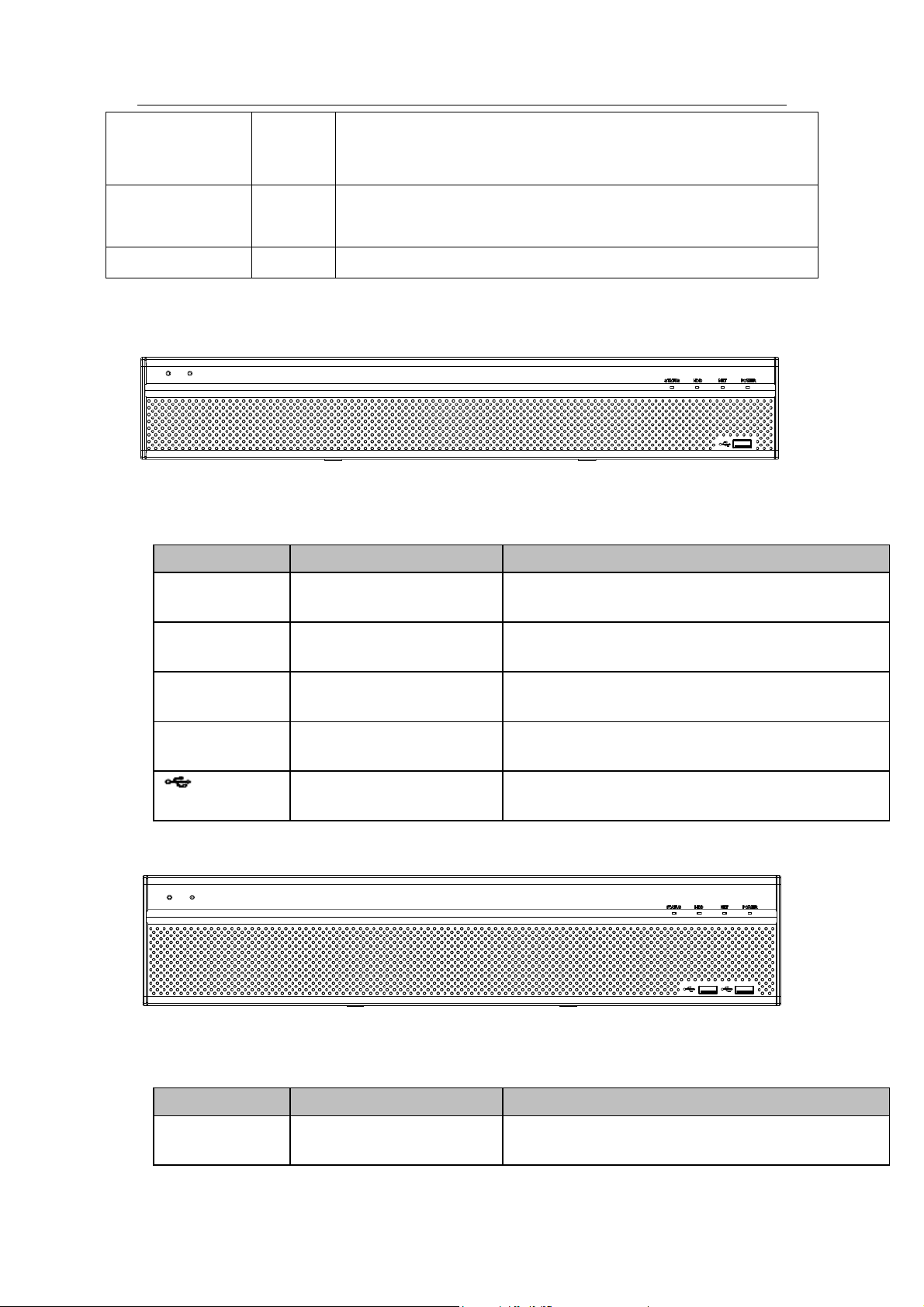
Standalone DVR User’s Manual
39
Status indication
light
Status
The light is on if device operates properly.
Power indication
light
PWR
Power indication light
IR Receiver
IR
It is to receive the signal from the remote control.
Icon
Name
Function
STATUS
Status indicator light
The blue light is on when the device is working
properly.
HDD
HDD status indicator
light
The blue light is on when the HDD is malfunction.
NET
Network status indicator
light
The blue light is on when the network connection is
abnormal.
POWER
Power status indicator light
The blue light is on when the power connection is
OK.
USB2.0 port
Connect to peripheral USB 2.0 storage device,
mouse, burner and etc.
Icon
Name
Function
STATUS
Status indicator light
The blue light is on when the device is working
properly.
2.1.3 Premium General 4-HDD 720P(S2)1.5U Series
The front panel is shown as below. See Figure 2-3.
Figure 2-3
Please refer to the following sheet for front panel button information.
2.1.4 Premium General 720P(S2) 2U Series
The front panel is shown as below. See Figure 2-4.
Please refer to the following sheet for front panel button information.
Figure 2-4
Page 50
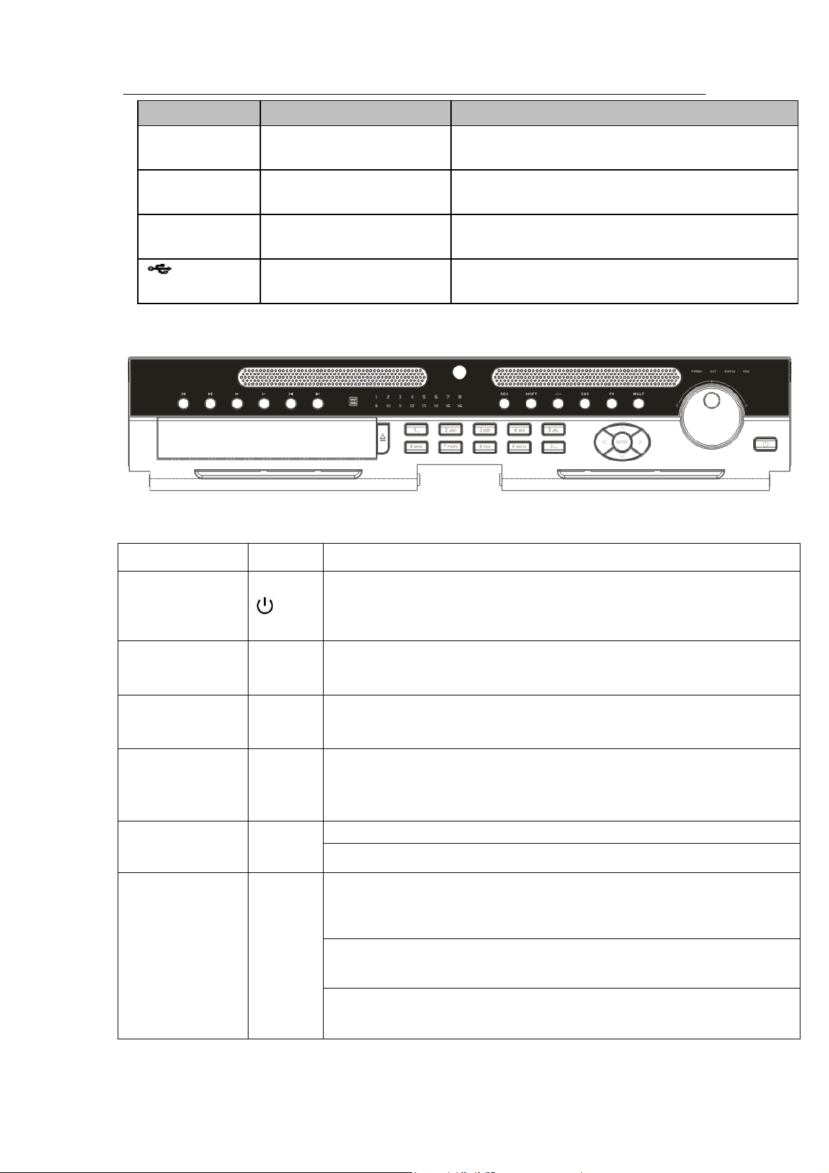
Standalone DVR User’s Manual
40
Icon
Name
Function
HDD
HDD status indicator
light
The blue light is on when the HDD is malfunction.
NET
Network status indicator
light
The blue light is on when the network connection is
abnormal.
POWER
Power status indicator light
The blue light is on when the power connection is
OK.
USB2.0 port
Connect to peripheral USB 2.0 storage device,
mouse, burner and etc.
Name
Icon
Function
Power button
Power button, press this button for three seconds to boot up or shut
down DVR.
Number button
0-9 and
etc
Input Arabic number
Switch channel
Record
REC
Manually stop/start recording, working with direction keys
or numeral keys to select the recording channel.
Input number
more than 10
-/--
If you want to input a number more than 10, please click this button and
then input.
ESC
ESC
Go to previous menu, or cancel current operation.
When playback, click it to restore real-time monitor mode.
Assistant
Fn
One-window monitor mode, click this button to display assistant
function: PTZ control and image color.
Backspace function: in numeral control or text control, press it for
1.5seconds to delete the previous character before the cursor.
In motion detection setup, working with Fn and direction keys to realize
setup.
2.1.5 Advanced 1080P 2U RAID Series
The front panel is shown as below. See Figure 2-5.
Figure 2-5
Please refer to the following sheet for front panel button information.
Page 51

Standalone DVR User’s Manual
41
In text mode, click it to switch between numeral, English
character(small/capitalized) and etc.
In HDD management interface, you can click it to switch HDD record
information and other information (Menu prompt)
Realize other special functions.
Window switch
Mult
Click it to switch one-window/multiple-window.
Shift
In textbox, click this button to switch between numeral,
English(Small/Capitalized),donation and etc.
Enable or disable tour.
Up/
Down
、
Activate current control, modify setup, and then move up and down.
Increase/decrease numeral.
Assistant function such as PTZ menu.
Left/
Right
Shift current activated control, and then move left and right.
When playback, click these buttons to control playback bar.
Slow play
Multiple slow play speeds or normal playback.
Fast play
Various fast speeds and normal playback.
Play previous
In playback mode, playback the previous video
Reverse/Pause
In normal playback or pause mode, click this button to reverse
playback
In reverse playback, click this button to pause playback.
Play Next
In playback mode, playback the next video
In menu setup, go to down ward of the dropdown list.
Play/Pause
In normal playback click this button to pause playback
In pause mode, click this button to resume playback.
Enter
ENTER
Confirm current operation
Go to default button
Go to menu
Shuttle(outer
ring)
In real-time monitor mode it works as left/right direction key.
Playback mode, counter clockwise to forward and clock wise to
backward.
Page 52

Standalone DVR User’s Manual
42
Jog(inner dial)
Up/down direction key.
Playback mode, turn the inner dial to realized frame by frame playback.
(Only applies to some special versions.)
USB port
To connect USB storage device, USB mouse.
Channel
indication light
1-16
It becomes on when system is recording.
IR Receiver
IR
It is to receive the signal from the remote control.
Power indication
light
POWER
Power indication light
Remote control
indication light
ACT
Remote control indication light
Status indication
light
STATUS
If there is Fn indication light, current status indication light is null.
HDD abnormal
indication light
HDD
The indication light is on when there is no HDD, HDD error occurred or
HDD capacity is below specified threshold value.
SN
Icon
Name
Function
1
GND
Ground port
2
Power socket
Power input port
2.2 Rear Panel
2.2.1 4/8-Channel Advanced 1080P 1.5U Series
This series products’ rear panel is shown as below. See Figure 2-6.
Figure 2-6
Please refer to the following sheet for detailed information.
Page 53

Standalone DVR User’s Manual
43
SN
Icon
Name
Function
3
Power switch
Power on/off button.
4
AUDIO IN
Audio input
port
Connect to microphone and etc to input signal.
5
MIC IN
Bidirectional
talk input port
Input bidirectioanl talk analog signal from microphone,
pick up.
6
MIC OUT
Bidirectional
talk output
port
Output bidirectional talk analog signal to sound box and
etc.
Bidirectional talk output.
Audio output of single-window monitor mode.
Audio output of single-window playback mode.
7
AUDIO OUT
Audio output
port
Connect to sound box and etc to output audio signal.
8
VIDEO OUT
Video output
port
Connect to output devices such as TV.
9
VIDEO IN
Video input
port
Connect to analog camera, video input signal.
10
1~16
Alarm input
port 1~16
There are four groups. The first group is from port 1
to port 4, the second group is from port 5 to port 8,
the third group is from port9 to port 12, the fourth
group is from port13 to port 16. They are to receive
the signal from the external alarm source. There are
two types; NO (normal open)/NC (normal close).
When your alarm input device is using external
power, please make sure the device and the NVR
have the same ground.
NO1~NO5
Alarm output
port 1~5
5 groups of alarm output ports. (Group 1: port
NO1 ~ C1,Group 2:port NO2 ~ C2,Group 3:port
NO3 ~ C3. 4:port NO4 ~ C4. 5:port NO5 ~
C5.).Output alarm signal to the alarm device. Please
make sure there is power to the external alarm
device.
NO:Normal open alarm output port.
NC:Normal close alarm output port.
C:Alarm output public end.
C1~C5
NC5
A
RS485
communicatio
n port
RS485_A port. It is the cable A. You can connect to the
control devices such as speed dome PTZ.
B
RS485_B.It is the cable B. You can connect to the control
devices such as speed dome PTZ.
Page 54
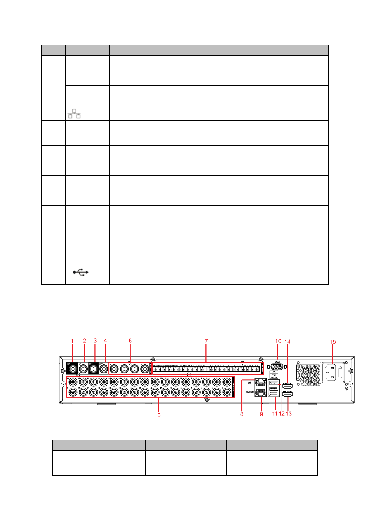
Standalone DVR User’s Manual
44
SN
Icon
Name
Function
T+、T-、R+、
R-
Four-cable
full-duplex
485 port.
T+, T-: Send out cable.
R+, R-: Input cable.
CTRL 12V
Control power
output
Turn off power output when the alarm is cancelled.
11
Network port
1000M Ethernet port
12
VGA
VGA video
output port
VGA video output port. Output analog video signal. It can
connect to the monitor to view analog video.
13
HDMI1
High definition
media
interface 1
High definition audio and video signal output port. It
transmits the same video signal as the VGA/TV.
Support mouse operation.
14
HDMI2
High definition
media
interface 2
HD video matrix output. Support zero-channel encoding
matrix output. Support tour.
15
eSATA
eSATA port
External SATA port. It can connect to the device of the
SATA port.
16
RS-232
RS232 debug
port
It is for general COM debug to configure IP address or
transfer transparent COM data.
17
USB2.0 port
Connect to mouse, USB storage media, USB-burner and
etc.
SN
Icon
Name
Function
1
MIC IN
Bidirectional talk input
port
Input bidirectioanl talk analog
signal from microphone, pick
2.2.2 16-Channel Advanced 1080P 1.5U/ Premium General 4-HDD 720P
1.5U/ Premium General 4-HDD 720P(S2)1.5U/ Premium General
720P(S2)2U Series
This series products’ rear panel is shown as below. See Figure 2-8.
Figure 2-7
Please refer to the following sheet for detailed information.
Page 55

Standalone DVR User’s Manual
45
SN
Icon
Name
Function
up.
2
MIC OUT
Bidirectional talk output
port
Output bidirectional talk
analog signal to sound box
and etc.
Bidirectional talk output.
Audio output of
single-window monitor
mode.
Audio output of
single-window playback
mode.
3
VIDEO OUT
Video output port
Connect to output devices
such as TV.
4
AUDIO OUT
Audio output port
Connect to sound box and
etc to output audio signal.
5
AUDIO IN
Audio input port
Connect to microphone and
etc to input audio signal.
6
VIDEO IN
Video input port
Connect to analog camera to
input video signal.
7
1~16
Alarm input port 1~16
There are four groups.
The first group is from
port 1 to port 4, the
second group is from
port 5 to port 8, the third
group is from port9 to
port 12, the fourth group
is from port13 to port 16.
They are to receive the
signal from the external
alarm source. There are
two types; NO (normal
open)/NC (normal
close).
When your alarm input
device is using external
power, please make
sure the device and the
NVR have the same
ground.
Page 56

Standalone DVR User’s Manual
46
SN
Icon
Name
Function
NO1~NO5
Alarm output port 1~5
5 groups of alarm output
ports. (Group 1 : port
NO1~ C1,Group 2:port
NO2~ C2,Group 3:port
NO3~C3. 4:port NO4~
C4. 5:port NO5 ~
C5.).Output alarm signal
to the alarm device.
Please make sure there
is power to the external
alarm device.
NO:Normal open alarm
output port.
NC:Normal close alarm
output port.
C:Alarm output public
end.
C1~C5
NC5
A
RS485 communication
port
RS485_A port. It is the cable
A. You can connect to the
control devices such as
speed dome PTZ.
B
RS485_B.It is the cable B.
You can connect to the
control devices such as
speed dome PTZ.
T+、T-、R+、R-
Four-cable full-duplex
485 port.
T+, T-: Send out cable.
R+, R-: Input cable.
CTRL 12V
Control power output
Turn off power output when
the alarm is cancelled.
8
Network port
1000M Ethernet port
9
RS-232
RS232 debug port
It is for general COM debug
to configure IP address or
transfer transparent COM
data.
10
VGA
VGA video output port
VGA video output port.
Output analog video signal. It
can connect to the monitor to
view analog video.
11
eSATA
eSATA port
External SATA port. It can
connect to the device of the
SATA port.
Page 57
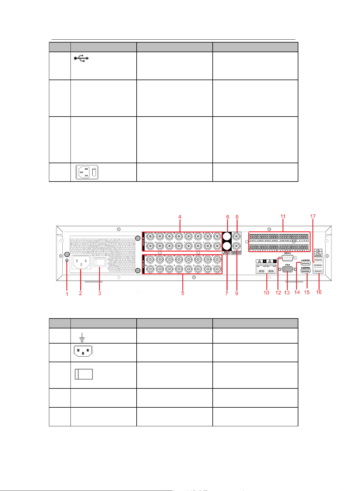
Standalone DVR User’s Manual
47
SN
Icon
Name
Function
12
USB2.0 port
Connect to mouse, USB
storage media, USB-burner
and etc.
13
HDMI2
High definition media
interface 2
HD video matrix output.
Support zero-channel
encoding matrix output.
Support tour.
14
HDMI1
High definition media
interface 1
High definition audio and
video signal output port. It
transmits the same video
signal as the VGA/TV.
Support mouse operation.
15
Power socket and power
switch
Power input port/power
on/off button.
SN
Icon
Name
Function
1
GND
Ground port
2
Power socket
Power input port
3
Power switch
Power on/off button.
4
AUDIO IN
Audio input port
Connect to microphone and
etc to input audio signal.
5
VIDEO IN
Video input port
Connect to analog camera to
input video signal.
2.2.3 4/8-Channel Advanced 1080P 2U Series
This series products’ rear panel is shown as below. See Figure 2-8.
Please refer to the following sheet for detailed information.
Figure 2-8
Page 58

Standalone DVR User’s Manual
48
SN
Icon
Name
Function
6
MIC IN
Bidirectional talk input
port
Input bidirectioanl talk analog
signal from microphone, pick
up.
7
MIC OUT
Bidirectional talk output
port
Output bidirectional talk
analog signal to sound box
and etc.
Bidirectional talk output.
Audio output of
single-window monitor
mode.
Audio output of
single-window playback
mode.
8
AUDIO OUT
Audio output port
Connect to sound box and
etc to output audio signal.
9
VIDEO OUT
Video output port
Connect to output devices
such as TV.
10
Network port
1000M Ethernet port
11
1~16
Alarm input port 1~16
There are four groups.
The first group is from
port 1 to port 4, the
second group is from
port 5 to port 8, the third
group is from port9 to
port 12, the fourth group
is from port13 to port 16.
They are to receive the
signal from the external
alarm source. There are
two types; NO (normal
open)/NC (normal
close).
When your alarm input
device is using external
power, please make
sure the device and the
NVR have the same
ground.
Page 59

Standalone DVR User’s Manual
49
SN
Icon
Name
Function
NO1~NO5
Alarm output port 1~5
5 groups of alarm output
ports. (Group 1 : port
NO1~ C1,Group 2:port
NO2~ C2,Group 3:port
NO3~C3. 4:port NO4~
C4. 5:port NO5 ~
C5.).Output alarm signal
to the alarm device.
Please make sure there
is power to the external
alarm device.
NO:Normal open alarm
output port.
NC:Normal close alarm
output port.
C:Alarm output public
end.
C1~C5
NC5
A
RS485 communication
port
RS485_A port. It is the cable
A. You can connect to the
control devices such as
speed dome PTZ.
B
RS485_B.It is the cable B.
You can connect to the
control devices such as
speed dome PTZ.
T+、T-、R+、R-
Four-cable full-duplex
485 port.
T+, T-: Send out cable.
R+, R-: Input cable.
CTRL 12V
Control power output
Turn off power output when
the alarm is cancelled.
12
RS232
RS232
RS232 debug port
13
VGA
VGA video output port
VGA video output port.
Output analog video signal. It
can connect to the monitor to
view analog video.
14
HDMI1
High definition media
interface 1
High definition audio and
video signal output port. It
transmits the same video
signal as the VGA/TV.
Support mouse operation.
15
HDMI2
High definition media
interface 2
HD video matrix output.
Support zero-channel
encoding matrix output.
Page 60

Standalone DVR User’s Manual
50
SN
Icon
Name
Function
Support tour.
16
eSATA
eSATA port
External SATA port. It can
connect to the device of the
SATA port.
17
USB2.0 port
Connect to mouse, USB
storage media, USB-burner
and etc.
SN
Icon
Name
Function
1
VIDEO OUT
Video output port
Connect to output devices
such as TV.
2
AUDIO OUT
Audio output port
Connect to sound box and
etc to output audio signal.
3
MIC IN
Bidirectional talk input
port
Input bidirectioanl talk analog
signal from microphone, pick
up.
4
MIC OUT
Bidirectional talk output
port
Output bidirectional talk
anaglo signal to sound box
and etc.
Bidirectional talk output.
Audio output of
single-window monitor
mode.
Audio output of
single-window playback
mode.
5
AUDIO IN
Audio input port
Connect to microphone and
2.2.4 16-Channel Advanced 1080P 2U/ Premium General 720P 2U/ Advanced 1080P 2U RAID Series
The 16-channel series products’ rear panel is shown as below. See Figure 2-9.
Please refer to the following sheet for detailed information.
Figure 2-9
Page 61

Standalone DVR User’s Manual
51
SN
Icon
Name
Function
etc to input audio signal.
6
VIDEO IN
VIDEO IN
Video input port
7
1~16
Alarm input port 1~16
There are four groups.
The first group is from
port 1 to port 4, the
second group is from
port 5 to port 8, the third
group is from port9 to
port 12, the fourth group
is from port13 to port 16.
They are to receive the
signal from the external
alarm source. There are
two types; NO (normal
open)/NC (normal
close).
When your alarm input
device is using external
power, please make
sure the device and the
NVR have the same
ground.
NO1~NO5
Alarm output port 1~5
5 groups of alarm output
ports. (Group 1 : port
NO1~ C1,Group 2:port
NO2~ C2,Group 3:port
NO3~C3. 4:port NO4~
C4. 5:port NO5 ~
C5.).Output alarm signal
to the alarm device.
Please make sure there
is power to the external
alarm device.
NO:Normal open alarm
output port.
NC:Normal close alarm
output port.
C:Alarm output public
end.
C1~C5
NC5
A
RS-485 communication
port
RS485_A port. It is the cable
A. You can connect to the
control devices such as
Page 62

Standalone DVR User’s Manual
52
SN
Icon
Name
Function
speed dome PTZ.
B
RS485_B.It is the cable B.
You can connect to the
control devices such as
speed dome PTZ.
T+、T-、R+、R-
Four-cable full-duplex
485 port.
T+, T-: Send out cable.
R+, R-: Input cable.
CTRL 12V
Control power output
Turn off power output when
the alarm is cancelled.
8
VGA
VGA video output port
VGA video output port.
Output analog video signal. It
can connect to the monitor to
view analog video.
9
RS-232
RS232 debug port
It is for general COM debug
to configure IP address or
transfer transparent COM
data.
10
USB2.0 port
Connect to mouse, USB
storage media, USB-burner
and etc.
11
Network port
1000M Ethernet port
12
eSATA
eSATA port
External SATA port. It can
connect to the device of the
SATA port.
13
HDMI2
High definition media
interface 2
HD video matrix output.
Support zero-channel
encoding matrix output.
Support tour.
14
HDMI1
High definition media
interface 1
High definition audio and
video signal output port. It
transmits the same video
signal as the VGA/TV.
Support mouse operation.
15
Power socket/power
switch button
Power input port and power
on-off button
16
GND
Ground port
When connect the Ethernet port, please use crossover cable to connect the PC and use
the straight cable to connect to the switch or router.
Page 63

Standalone DVR User’s Manual
53
2.3 Connection Sample
2.3.1 Advanced 1080P 1.5U Series
Please refer to the following figure for detailed information. See Figure 2-10.
The following interface is based on the 8-channel series product.
Figure 2-10
2.3.2 16-Channel Advanced 1080P 1.5U / Premium General 4-HDD 720P
1.5U/ Premium General 4-HDD 720P(S2)1.5U/ Premium General
720P(S2)2U Series
Please refer to the following figure for detailed information. See Figure 2-11.
The following interface is based on the 32-channel premium general 4-HDD 720P 1.5U
series product.
Page 64

Standalone DVR User’s Manual
54
Figure 2-11
2.3.3 4/8-Channel Advanced 1080P 2U Series
Please refer to the following figure for detailed information. See Figure 2-12.
Page 65
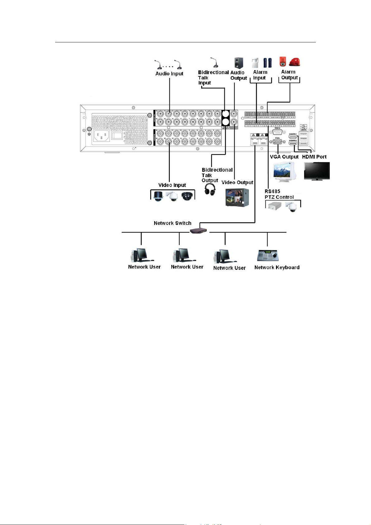
Standalone DVR User’s Manual
55
Figure 2-12
2.3.4 16-Channel Advanced 1080P 1.5U / Premium General 720P 2U/ Advanced 1080P 2U RAID Series
Please refer to Figure 2-13 for connection sample.
The following figure is based on 32-channel premium general 720P 2U series product.
Page 66

Standalone DVR User’s Manual
56
Figure 2-13
2.4 Remote Control
The remote control interface is shown as in Figure 2-14.
Please note remote control is not our standard accessory and it is not included in the
accessory bag.
Page 67

Standalone DVR User’s Manual
57
Serial Number
Name
Function
1
Power button
Click it to boot up or shut down
the device.
2
Address
Click it to input device number, so
that you can control it.
3
Forward
Various forward speeds and
normal speed playback.
4
Slow play
Multiple slow play speeds or
normal playback.
5
Next record
In playback mode, playback the
next video.
6
Previous record
In playback mode, playback the
previous video.
7
Play/Pause
In pause mode, click this button
to realize normal playback.
In normal playback click this
button to pause playback.
In real-time monitor mode, click
this button to enter video search
menu.
Reverse/pause
Reverse playback pause mode,
Figure 2-14
Page 68

Standalone DVR User’s Manual
58
8
click this button to realize normal
playback.
In reverse playback click this
button to pause playback.
9
Esc.
Go back to previous menu or
cancel current operation (close
upper interface or control)
10
Record
Start or stop record manually
In record interface, working with
the direction buttons to select the
record channel.
Click this button for at least 1.5
seconds, system can go to the
Manual Record interface.
11
Direction keys
Switch current activated control,
go to left or right.
In playback mode, it is to control
the playback process bar.
Aux function(such as switch the
PTZ menu)
12
Enter /menu key
go to default button
go to the menu
13
Multiple-window switch
Switch between multiple-window
and one-window.
14
Fn
In 1-ch monitor mode: pop up
assistant function: PTZ control
and Video color.
Switch the PTZ control menu in
PTZ control interface.
In motion detection interface,
working with direction keys to
complete setup.
In text mode, click it to delete
character.
15
0-9 number key
Input password, channel or
switch channel.
Shift is the button to switch the
input method.
Left click
mouse
System pops up password input dialogue box if you have not logged in.
In real-time monitor mode, you can go to the main menu.
2.5 Mouse Control
Page 69
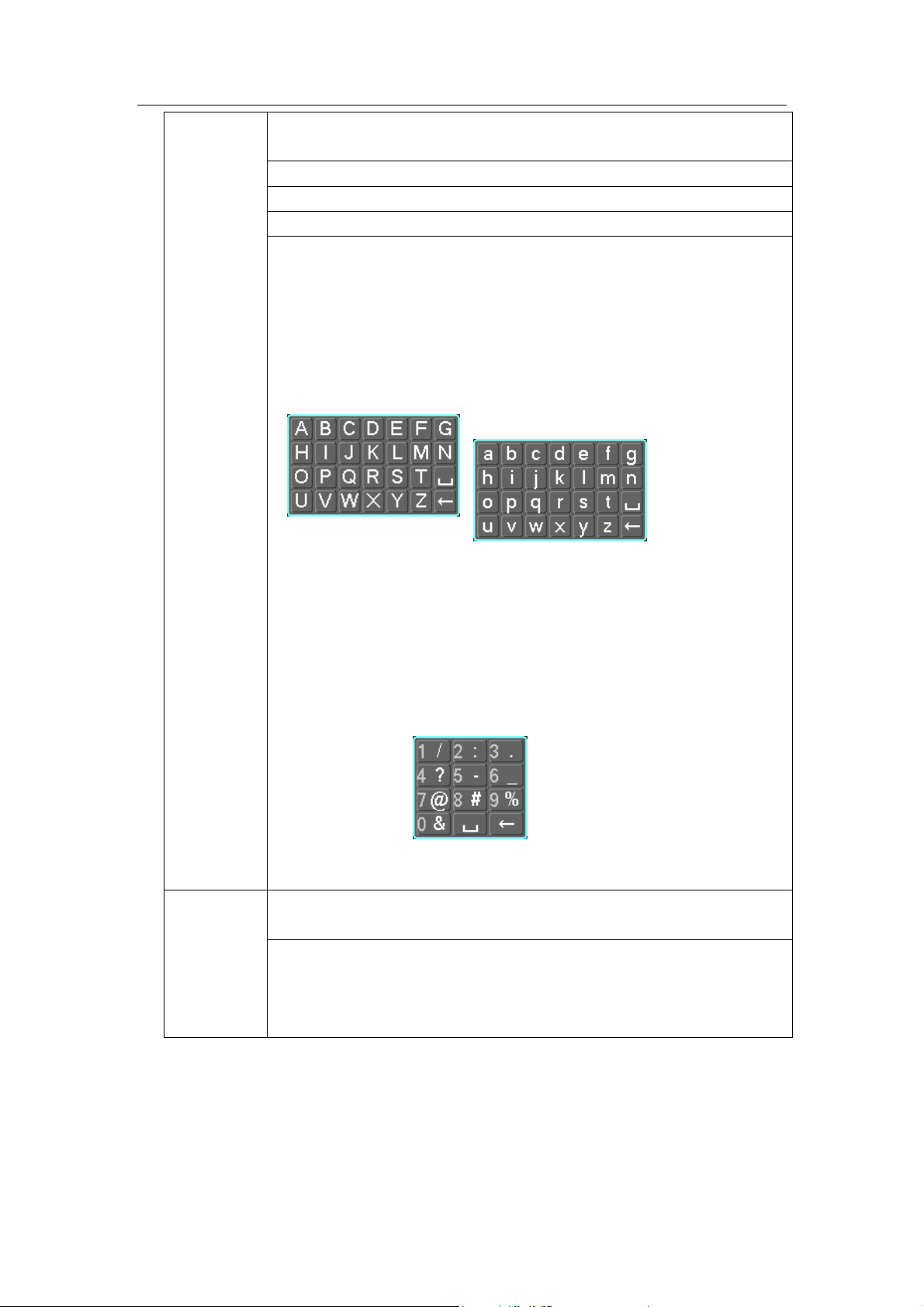
Standalone DVR User’s Manual
59
When you have selected one menu item, left click mouse to view menu
content.
Implement the control operation.
Modify checkbox or motion detection status.
Click combo box to pop up drop down list
In input box, you can select input methods. Left click the corresponding
button on the panel you can input numeral/English character
(small/capitalized). Here ← stands for backspace button. _ stands for
space button.
In English input mode: _stands for input a backspace icon and ←
stands for deleting the previous character.
In numeral input mode: _ stands for clear and ← stands for
deleting the previous numeral.
When input special sign, you can click corresponding numeral in the
front panel to input. For example, click numeral 1 you can input“/” , or
you can click the numeral in the on-screen keyboard directly.
Double left
click mouse
Implement special control operation such as double click one item in
the file list to playback the video.
In multiple-window mode, double left click one channel to view in
full-window.
Double left click current video again to go back to previous
multiple-window mode.
Page 70
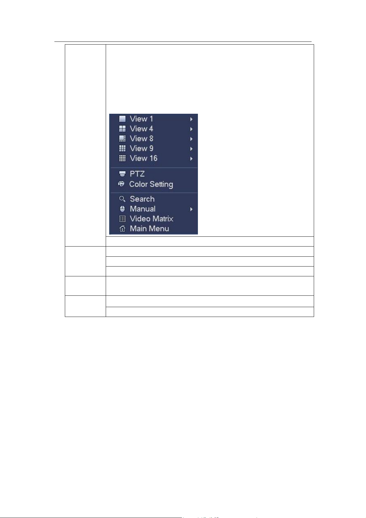
Standalone DVR User’s Manual
60
Right click
mouse
In real-time monitor mode, pops up shortcut menu: one-window,
four-window, nine-window and sixteen-window, Pan/Tilt/Zoom, color
setting, search, record, alarm input, alarm output, main menu.
Among which, Pan/Tilt/Zoom and color setting applies for current
selected channel.
If you are in multiple-window mode, system automatically switches to
the corresponding channel.
Exit current menu without saving the modification.
Press
middle
button
In numeral input box: Increase or decrease numeral value.
Switch the items in the check box.
Page up or page down
Move
mouse
Select current control or move control
Drag
mouse
Select motion detection zone
Select privacy mask zone.
2.6 Virtual Keyboard & Front Panel
2.6.1 Virtual Keyboard
The system supports two input methods: numeral input and English character (small and
capitalized) input.
Move the cursor to the text column, the text is shown as blue, input button pops up on the
right. Click that button to switch between numeral input and English input (capitalized and
small), Use > or < to shift between small character and capitalized character.
2.6.2 Front Panel
Move the cursor to the text column. Click Fn key and use direction keys to select number
you wanted. Please click enter button to input.
Page 71

Standalone DVR User’s Manual
61
i
q
102436008 iidq
i
d
i
m
i
m
i
q
i
h
i
D
i
h
i
D
3 Installation and Connections
Note: All the installation and operations here should conform to your local electric
safety rules.
3.1 Check Unpacked DVR
When you receive the DVR from the forwarding agent, please check whether there is any
visible damage. The protective materials used for the package of the DVR can protect
most accidental clashes during transportation. Then you can open the box to check the
accessories.
Please check the items in accordance with the list. Finally you can remove the protective
film of the DVR.
Note
Remote control is not a standard accessory and it is not included in the accessory bag.
3.2 About Front Panel and Real Panel
The model in the front panel is very important; please check according to your purchase
order.
The label in the rear panel is very important too. Usually we need you to represent the
serial number when we provide the service after sales.
3.3 HDD Installation
3.3.1 HDD Calculation
Calculate total capacity needed by each DVR according to video recording (video
recording type and video file storage time).
Step 1: According to Formula (1) to calculate storage capacity
each channel needed for each hour, unit Mbyte.
In the formula:
means the bit rate, unit Kbit/s
Step 2: After video time requirement is confirmed, according to Formula (2) to calculate
the storage capacity
, which is storage of each channel needed unit Mbyte.
=
×
×
In the formula:
means the recording time for each day (hour)
that is the capacity of
(1)
(2)
means number of days for which the video shall be
kept
Page 72

Standalone DVR User’s Manual
62
T
q
c
i
iT
mq
1
T
q
c
i
iT
mq
1
Bit stream size
(max)
File size
Bit stream size
(max)
File size
96K
42M
128K
56M
160K
70M
192K
84M
224K
98M
256K
112M
320K
140M
384K
168M
448K
196M
512K
225M
640K
281M
768K
337M
896K
393M
1024K
450M
1280K
562M
1536K
675M
1792K
787M
2048K
900M
3072Kbps
1350M
4096K
1800M
6144Kbps
2700M
8192Kbps
3600M
Step 3: According to Formula (3) to calculate total capacity (accumulation)
that is
needed for all channels in the DVR during scheduled video recording.
(3)
In the formula: cmeans total number of channels in one DVR
Step 4: According to Formula (4) to calculate total capacity (accumulation)
that is
needed for all channels in DVR during alarm video recording (including motion
detection).
×a% (4)
In the formula:a% means alarm occurrence rate
You can refer to the following sheet for the file size in one hour per channel. (All the data
listed below are for reference only.)
Note
All information listed in the above sheet for reference only. We are not reliable for any
damage or loss resulting from it.
For the space marked by the HDD manufacturer, 1K=1000, while for the computer
OS, 1K=1024. So, the space recognized by the computer system is less than the
marked space on the HDD. Please pay attention to it.
All HDD space marked by the HDD manufacturer is shown as below: 1T=1000G,
1G=1000M, 1M=1000K, 1K=1000.
All HDD space marked by the HDD manufacturer shall become the computer OS
space after the corresponding calculation. For example:
1T(marked by the HDD manufacturer)=1000G/(1.024*1.024*1.024)=931G(OS space),
500G=500G/(1.024*1.024*1.024)=465G
3.3.2 HDD Installation
Page 73
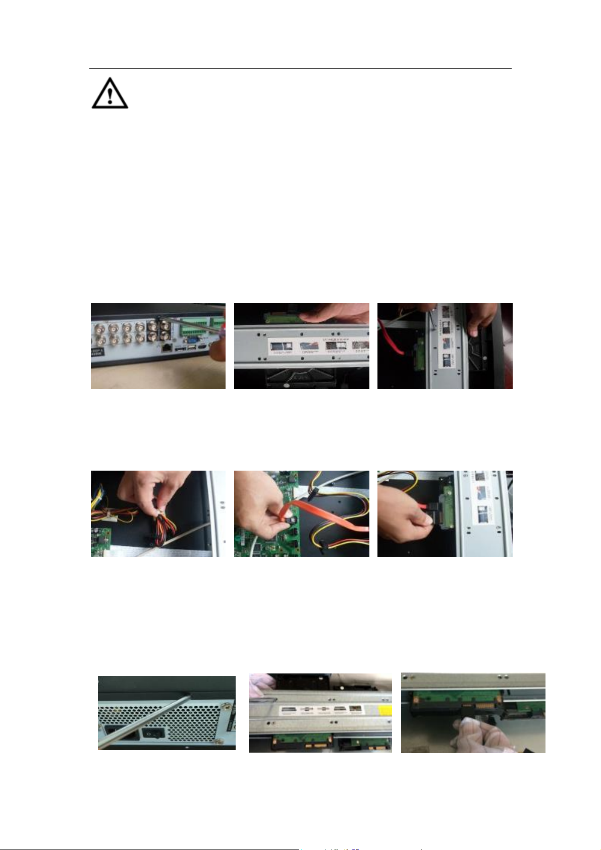
Standalone DVR User’s Manual
63
① Loosen the screws of the
upper cover.
② Place the HDD in
accordance with the four
holes in the bottom.
③ Use four screws to secure
the HDD.
④ Unfasten the HDD power
cable.
⑤ Use special data cable to
connect the HDD and the
SATA port.
⑥ Insert the HDD power cable
and then put the cover back.
Secure firmly.
Important
Shut down the device and unplug the power cable before you install the HDD.
Always use the HDD for the surveillance product recommended by the
manufacturer.
All figurers listed below for reference only. Slight difference may be found on
the front or rear panel.
You can refer to the User’s Manual for recommended HDD brand. Please follow the
instructions below to install hard disk. This series DVR max supports 8 SATA HDDs.
Please use HDD of 7200rpm or higher.
3.3.2.1 1.5U series
This series DVR max has four SATA HDDs.
3.3.2.2 2U
Page 74

Standalone DVR User’s Manual
64
①Loosen the screws of the upper
cover and then remove the cover.
②Fix the HDD on the bracket. If
you want to install the HDD on the
bottom bracket, you need to
remove the top bracket first.
③Connect one end of the HDD
data cable to one HDD.
④ Connect the other end of the
HDD data cable to the mainboard.
⑤Connect the power cable to
the HDD.
⑥Put the cover back and then fix.
① Remove the HDD box from the device.
②Put the HDD to the box and then use the screws to secure.
③ Insert the HDD box to the device. Please make sure
the HDD box handle is up in case it collides with the front
panel.
④ After you inserted the HDD box, put the handle back.
Important:
If the HDD amount is less than four, you do not need to install the HDD bracket.
When there is a bracket, please make sure the installation direction of HDDs is the same.
3.3.2.3 3U series
3.3.2.4 Removable Case
Page 75

Standalone DVR User’s Manual
65
① Insert the key to the hole on the front panel.
② Open the front panel.
③ Insert the HDD to the clip and adjust the handle
of the HDD to secure it.
④ Put the front panel back and then use the key to
secure the front panel.
① Line up the one side of the handle to the
HDD (The side of no port)
② Use screwdriver to fix the handle on the
HDD.
HDD Handle Installation
3.4 Rack Installation
The DVR occupies 1.5U/2U rack units of vertical rack space.
Use twelve screws to fix the unit
Please make sure the indoor temperature is below 35℃ (95°f).
Please make sure there is 15cm (6 inches) space around the device to guarantee
sound ventilation.
Please install from the bottom to the top.
If there are more accessories connected in the rack, please take precaution
measures in case the rack power is overload.
Page 76

Standalone DVR User’s Manual
66
3.5 Connecting Power Supply
Please check input voltage and device power button match or not.
We recommend you use UPS to guarantee steady operation, DVR life span, and other
peripheral equipments operation such as cameras.
3.6 Connecting Video Input and Output Devices
3.6.1 Connecting Video Input
The video input interface is BNC. The input video format includes: PAL/NTSC BNC
(1.0VB
The input video format: BNC(0.8VP-P,75Ω).
The video signal should comply with your national standards.
The input video signal shall have high SNR, low distortion; low interference, natural color
and suitable lightness.
Guarantee the stability and reliability of the camera signal:
The camera shall be installed in a cool, dry place away from direct sunlight, inflammable,
explosive substances and etc.
The camera and the DVR should have the same grounding to ensure the normal
operation of the camera.
Guarantee stability and reliability of the transmission lineBTTTB
Please use high quality, sound shielded BNC. Please select suitable BNC model
according to the transmission distance.
If the distance is too long, you should use twisted pair cable, and you can add video
compensation devices or use optical fiber to ensure video quality.
You should keep the video signal away from the strong electromagnetic interference,
especially the high tension current.
Keep connection lugs in well contactBTTTB
The signal line and shielded wire should be fixed firmly and in well connection. Avoid dry
joint, lap welding and oxidation.BTTT
3.6.2 Connecting Video Output
Video output includes a TBNC(PAL/NTSC, 1.0VP- P, 75Ω)output, a VGA output and a
HDMI output.
System supports BNC, VGA and HDMI output at the same time.
When you are using pc-type monitor to replace the monitor, please pay attention to the
following points:
To defer aging, do not allow the pc monitor to run for a long time.
Regular demagnetization will keep device maintain proper status.
Keep it away from strong electromagnetic interference devices.
Using TV as video output device is not a reliable substitution method. You also need to
reduce the working hour and control the interference from power supply and other devices.
The low quality TV may result in device damage.
P- P ,
B75Ω.).
Page 77

Standalone DVR User’s Manual
67
3.7 Connecting Audio Input & Output, Bidirectional Audio
3.7.1 Audio Input
BNC port is adopted for audio input port.
Due to high impedance of audio input, please use active sound pick-up.
Audio transmission is similar to video transmission. Try to avoid interference, dry joint,
loose contact and it shall be away from high tension current.
3.7.2 Audio Output
The audio output signal parameter is usually over 200mv 1KΩ (BNC). It can directly
connect to low impedance earphone, active sound box or amplifier-drive audio output
device.
If the sound box and the pick-up cannot be separated spatially, it is easy to arouse
squeaking. In this case you can adopt the following measures:
Use better sound pick-up with better directing property.
Reduce the volume of the sound box.
Using more sound-absorbing materials in decoration can reduce voice echo and
improve acoustics environment.
Adjust the layout to reduce happening of the squeaking.
3.8 Alarm Input and Output Connection
Please read the followings before connecting.
1. Alarm input
a. Please make sure alarm input mode is grounding alarm input.
b. Grounding signal is needed for alarm input.
c. Alarm input needs the low level voltage signal.
d.Alarm input mode can be either NC (normal Open) or NO (Normal Close)
e. When you are connecting two DVRs or you are connecting one DVR and one other
device, please use a relay to separate them,
2. Alarm output
The alarm output port should not be connected to high power load directly (It shall be less
than 1A) to avoid high current which may result in relay damage. Please use the co
contactor to realize the connection between the alarm output port and the load.
3. How to connect PTZ decoder
a. Ensure the decoder has the same grounding with DVR, otherwise you may not control
the PTZ. Shielded twisted wire is recommended and the shielded layer is used to connect
to the grounding.
b. Avoid high voltage. Ensure proper wiring and some thunder protection measures.
c. For too long signal wires, 120Ω should be parallel connected between A, B lines on the
far end to reduce reflection and guarantee the signal quality.
d. “485 A, B” of DVR cannot parallel connect with “485 port” of other device.
Page 78

Standalone DVR User’s Manual
68
1,2,3,4,5,6,
7,8,9,10,11,
12,13,14,15,16
ALARM 1 to ALARM 16. The alarm becomes active in low voltage.
NO1 C1,NO2 C2,
NO3 C3,NO4 C4,
NO6 C6
The first four are four groups of normal open activation output (on/off
button)
NO5 C5 NC5
NO5 C5 NC5 is a group of NO/NC activation output (on/off button)
CTRL 12V
Control power output. For external alarm, you need to close the
device power to cancel the alarm.
+12V
It is external power input. Need the peripheral equipment to provide
+12V power (below 1A).
Earth cable.
A/B
485 communication port. They are used to control devices such as
decoder.
T+,T-,R+,R-
They are four-wire double duplex RS485 port
T+ T-: output wire
R+ R-: input wire
e. The voltage between of A,B lines of the decoder should be less than 5v.
4. Please make sure the front-end device has soundly earthed.
Improper grounding may result in chip damage.
3.8.1 Alarm Input and Output Details
Important
Please refer to the specifications for the alarm input and output channel amount.
Do not merely count the alarm input and out channel amount according to the ports
on the rear panel.
Figure 3-1
3.8.2 Alarm Input Port
Please refer to the following sheet for more information.
Page 79

Standalone DVR User’s Manual
69
Model:
JRC-27F
Material of the
touch
Silver
Rating
(Resistance
Load)
Rated switch capacity
30VDC 2A, 125VAC 1A
Maximum switch power
125VA 160W
Maximum switch voltage
250VAC, 220VDC
Maximum switch currency
1A
Insulation
Between touches with same
polarity
1000VAC 1minute
Between touches with different
polarity
1000VAC 1minute
Between touch and winding
1000VAC 1minute
Surge voltage
Between touches with same
polarity
1500V (10×160us)
Length of open
time
3ms max
Grounding alarm inputs. Normal open or Normal close type)
Please parallel connect COM end and GND end of the alarm detector (Provide
external power to the alarm detector).
Please parallel connect the Ground of the DVR and the ground of the alarm detector.
Please connect the NC port of the alarm sensor to the DVR alarm input(ALARM)
Use the same ground with that of DVR if you use external power to the alarm device.
Figure 3-2
3.8.3 Alarm Output Port
Provide external power to external alarm device.
To avoid overloading, please read the following relay parameters sheet carefully.
RS485 A/B cable is for the A/B cable of the PTZ decoder.
T+,T-,R+,R- are four-wire double duplex RS485 port.
T+ T-: output wire
R+ R-: input wire
Relay Specification
Page 80
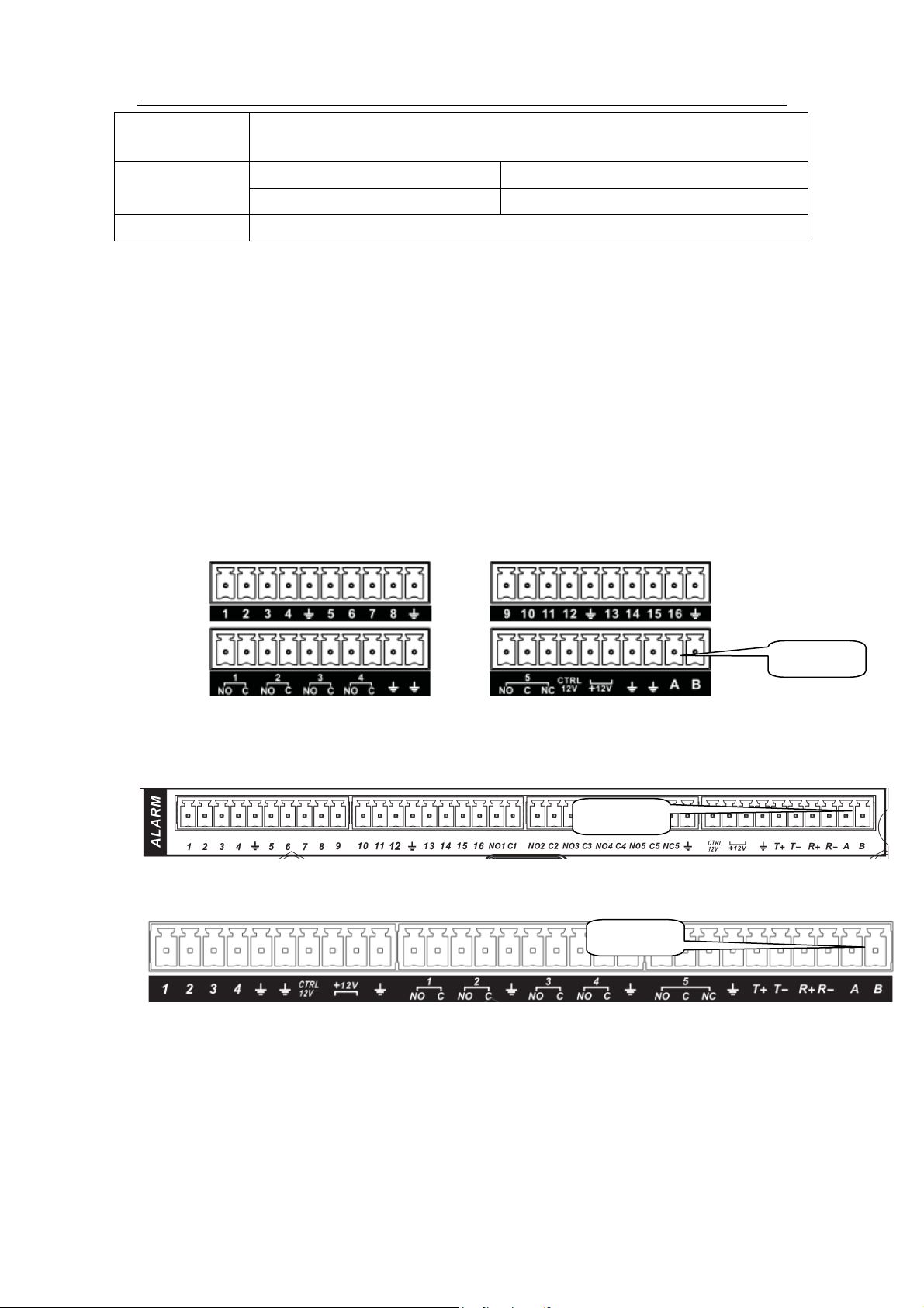
Standalone DVR User’s Manual
70
Length of close
time
3ms max
Longevity
Mechanical
50×106 times (3Hz)
Electrical
200×103 times (0.5Hz)
Temperature
-40℃ ~+70℃
485 Port
485 Port
485 Port
3.9 RS485
When the DVR receives a camera control command, it transmits that command up the coaxial
cable to the PTZ device. RS485 is a single-direction protocol; the PTZ device can’t return any
data to the unit. To enable the operation, connect the PTZ device to the RS485 (A,B) input on
the DVR.
Since RS485 is disabled by default for each camera, you must enable the PTZ settings first.
This series DVRs support multiple protocols such as Pelco-D, Pelco-P.
To connect PTZ devices to the DVR:
1. Connect RS485 A,B on the DVR rear panel.
2. Connect the other end of the cable to the proper pins in the connector on the camera.
3. Please follow the instructions to configure a camera to enable each PTZ device on the
DVR.
Figure 3-3
Figure 3-4
Figure 3-5
Page 81

Standalone DVR User’s Manual
71
485 Port
485 Port
Figure 3-6
Figure 3-7
3.10 Other Interfaces
There are still other interfaces on the DVR, such as USB ports.
Page 82

Standalone DVR User’s Manual
72
4 Overview of Navigation and Controls
4.1 Boot up and Shutdown
4.1.1 Boot up
Before the boot up, please make sure:
The rated input voltage matches the device power on-off button. Please make sure
the power wire connection is OK. Then click the power on-off button.
Always use the stable current, if necessary UPS is a best alternative measure.
Please follow the steps listed below to boot up the device.
Connect the device to the monitor and then connect a mouse.
Connect power cable.
Click the power button at the front or rear panel and then boot up the device. After
device booted up, the system is in multiple-channel display mode by default.
4.1.2 Shutdown
Note
When you see corresponding dialogue box “System is shutting down…” Do not click
power on-off button directly.
Do not unplug the power cable or click power on-off button to shutdown device
directly when device is running (especially when it is recording.)
There are three ways for you to log out.
a) Main menu (RECOMMENDED)
From Main Menu->Shutdown, select shutdown from dropdown list.
Click OK button, you can see device shuts down.
b) From power on-off button on the front panel or remote control
Press the power on-off button on the DVR front panel or remote control for more than 3
seconds to shutdown the device.
c) From power on-off button on the rear panel.
4.1.3 Auto Resume after Power Failure
The system can automatically backup video and resume previous working status after
power failure.
4.1.4 Replace Button Battery
Please make sure to use the same battery model if possible.
We recommend replace battery regularly (such as one-year) to guarantee system time
accuracy.
Note:
Before replacement, please save the system setup, otherwise, you may lose the
data completely!
4.2 Change/Reset Password
Page 83
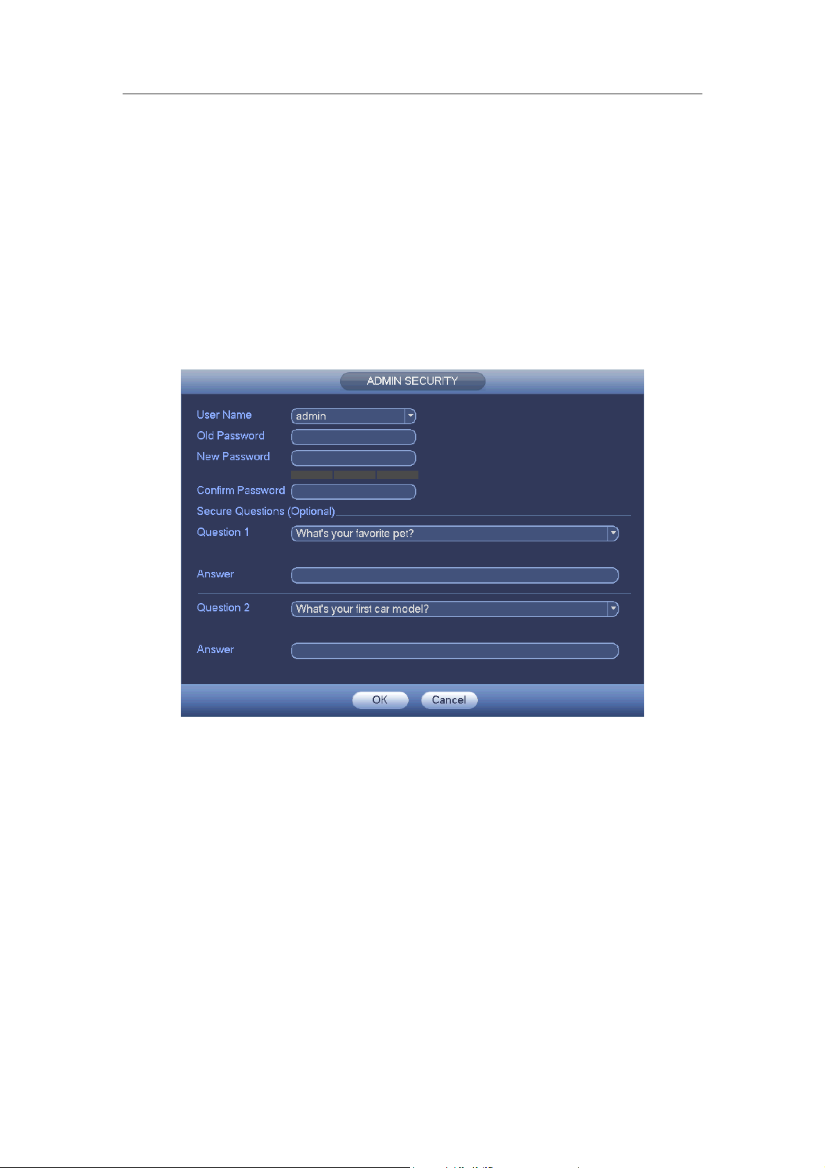
Standalone DVR User’s Manual
73
4.2.1 Change Password
For your own safety, please change your administrator default password after your
first login.
After system booted up, you can see the following interface if it is your first login or you
have restored default setup. See Figure 4-1. Please input old password and then input
new password twice to confirm the change.
The default administrator user name is admin and the password is admin.
You can set security questions here to reset the password in case you forgot. System
supports customized setup. Please note you need to set two security questions at the
same time. When you reset the password, you need to answer these two security
questions too.
For reset information, please refer to chapter 4.2.2.
Figure 4-1
Click Cancel button, system pops up the following interface for you to confirm. See Figure
4-2.
Check the box here, system will not pop up the change password interface the next time.
Page 84
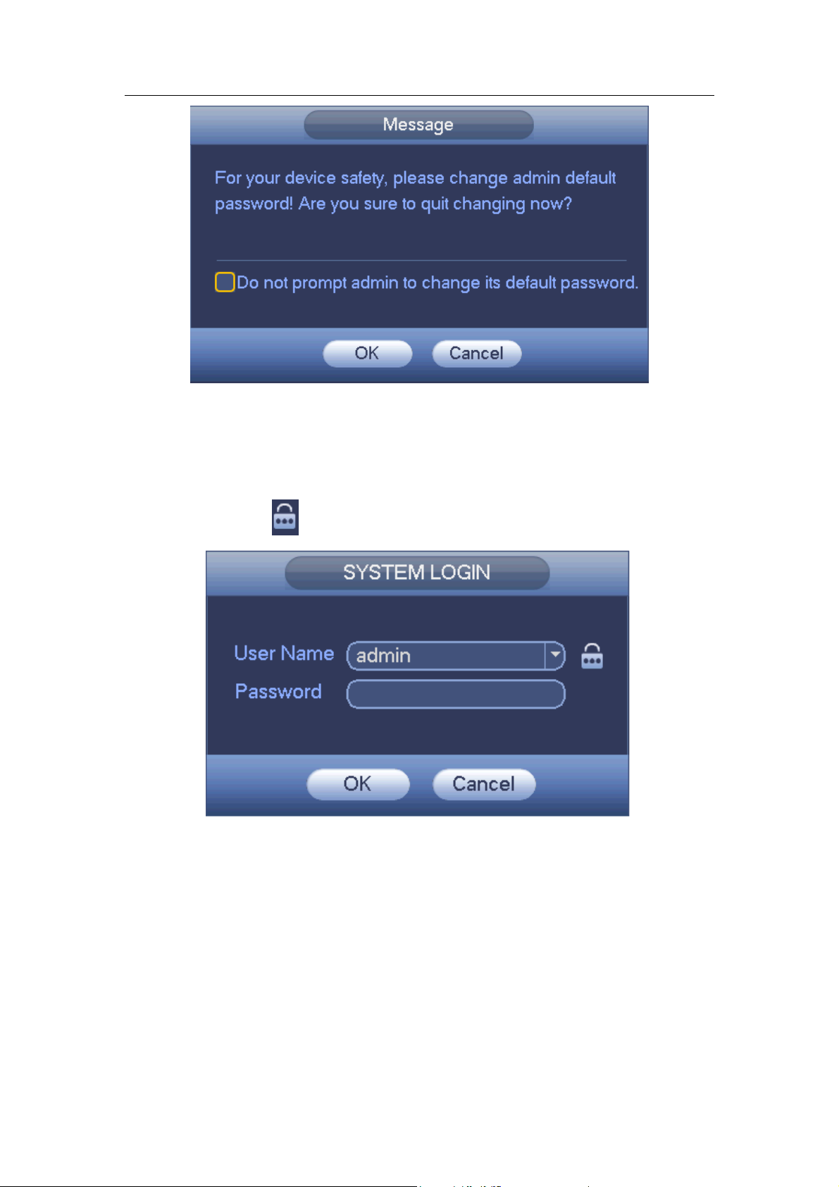
Standalone DVR User’s Manual
74
Figure 4-2
4.2.2 Reset Password
Once you forgot password, you can answer the security questions you set in chapter 4.2.1
to reset the password.
In login interface, click . See Figure 4-7.
Figure 4-3
System pops up the following dialogue box, please answer the security questions and
then input the new password twice. See Figure 4-4.
Page 85
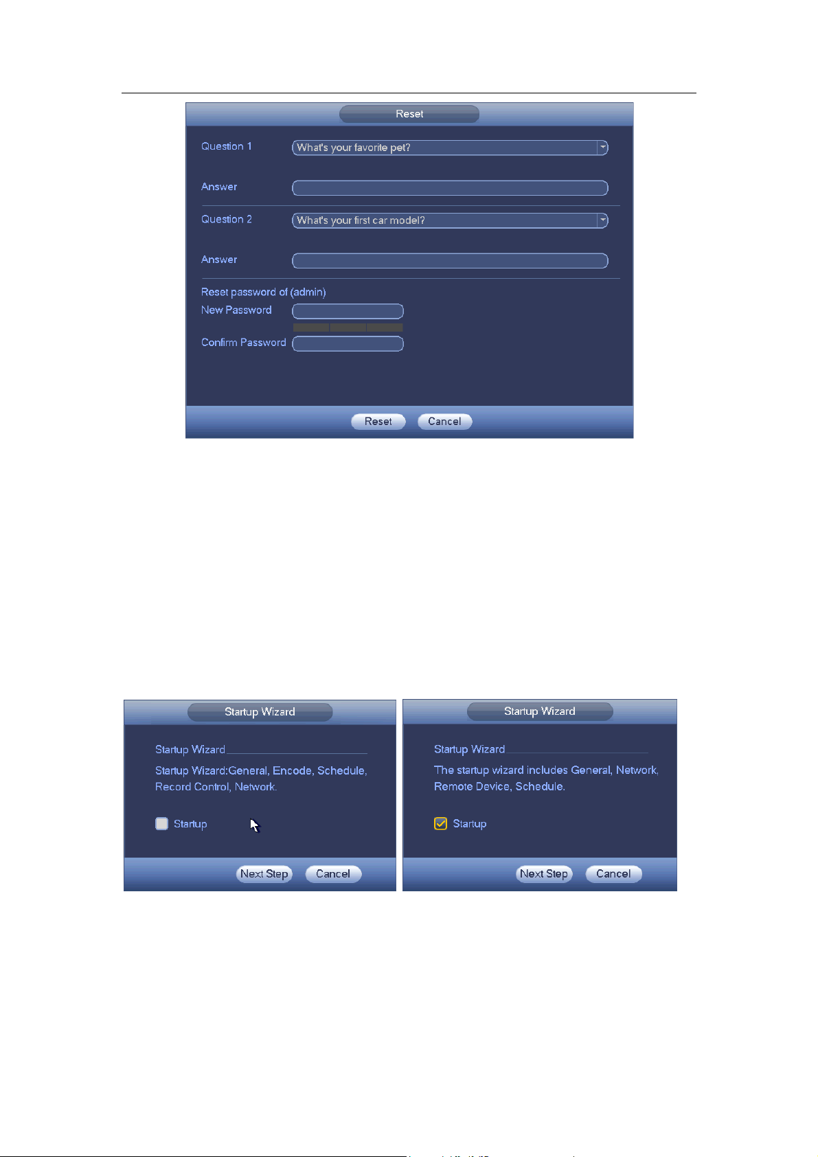
Standalone DVR User’s Manual
75
Figure 4-4
4.3 Startup Wizard
After changed admin password interface, it goes to startup wizard.
Click Cancel/Next button, you can see system goes to login interface.
Tips
Check the box Startup button here, system goes to startup wizard again when it boots up
the next time.
Cancel the Startup button, system goes to the login interface directly when it boots up the
next time.
General Series Hybrid Series
Figure 4-5
Click Cancel button or Next Step button, system goes to login interface. See Figure 4-6.
System consists of three accounts:
Username: admin. Password: admin. (administrator, local and network)
Username: 888888. Password: 888888. (administrator, local only)
Page 86
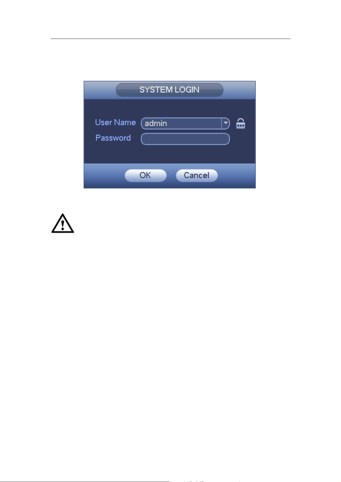
Standalone DVR User’s Manual
76
Username: default. Password: default (hidden user). Hidden user “default” is for
system interior use only and can not be deleted. When there is no login user, hidden
user “default” automatically login. You can set some rights such as monitor for this
user so that you can view some channels without login.
Figure 4-6
Important
For security reason, please change factory default password after you first login.
Continuous three times login failure will result in system alarm and five times login
failure will result in account lock!
Please reboot the device or wait for 30 minutes if your account has been locked. You
can go to main menu->Setting->Event->Abnormality->Network->Illegal login to set
customized account lock time.
After input corresponding user name and password, you can click OK button. System
goes to the startup wizard.
When there are all analog channels, the startup wizard includes general, encode,
schedule, record control and network.
When there is an IP channel, the startup wizard includes general, network, remote
device and schedule.
Click OK button, you can go to General interface. See Figure 4-7.
For detailed information, please refer to chapter 4.11.5.1.
Page 87
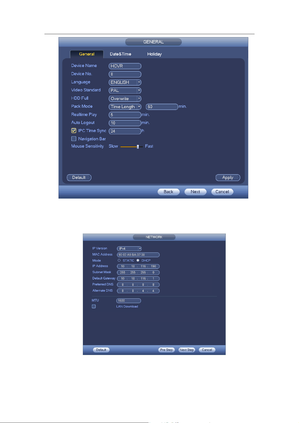
Standalone DVR User’s Manual
77
Figure 4-7
Click Next button, you can go to network interface. See Figure 4-8.
For detailed information, please refer to chapter 4.10.3.
Figure 4-8
Click Next button, you can go to Schedule interface. See Figure 4-9.
Page 88
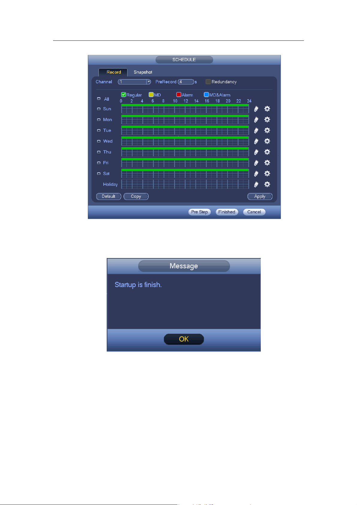
Standalone DVR User’s Manual
78
For detailed information, please refer to chapter 4.11.4.1.1.
Figure 4-9
Click Finish button, system pops up a dialogue box. Click the OK button, the startup
wizard is complete. See Figure 4-10.
Figure 4-10
4.4 Preview
4.4.1 Live Viewing
After you logged in, the system is in live viewing mode. You can see system date, time,
channel name and window No. See Figure 4-11. If you want to change system date
and time, you can refer to general settings (Main Menu->Setting->System->General).
If you want to modify the channel name, please refer to the CAM name settings (Main
Menu->Camera->CAM name)
Page 89
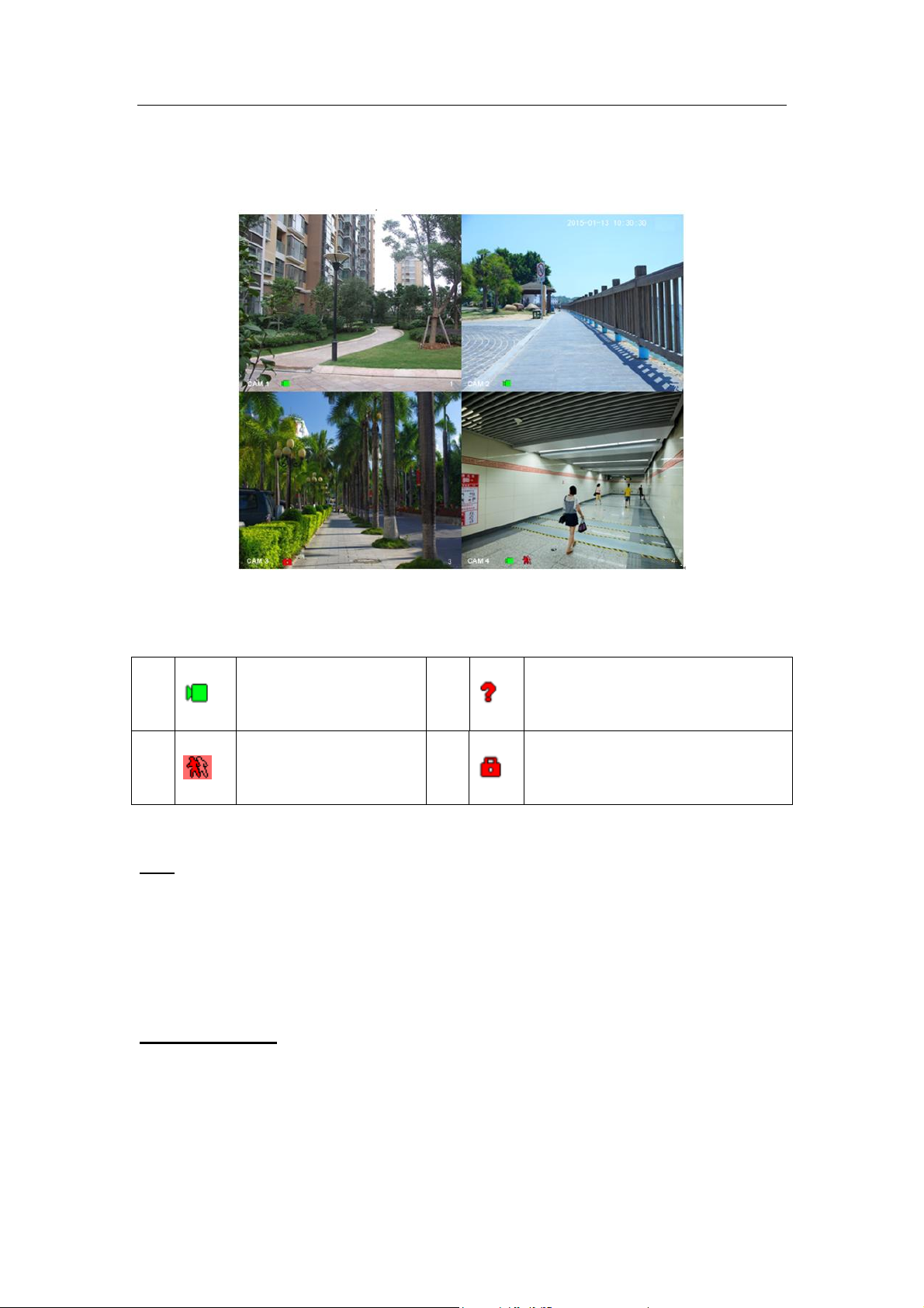
Standalone DVR User’s Manual
79
1
When current channel
is recording, system
displays this icon.
3
When video loss alarm occurs,
system displays this icon.
2
When motion detection
alarm occurs, system
displays this icon.
4
When current channel is in monitor
lock status, system displays this
icon.
At the right corner of the each window, you can see there is a window serial number.
Once the channel sequence is random or you have changed the channel name, you
can use this window number to confirm current channel name so that you can search
the record or playback.
Figure 4-11
Please refer to the following sheet for detailed information.
Tips
Preview drag: If you want to change position of channel 1 and channel 2 when you
are previewing, you can left click mouse in the channel 1 and then drag to channel
2, release mouse you can switch channel 1 and channel 2 positions.
Use mouse middle button to control window split: You can use mouse middle
button to switch window split amount.
Preview Control
The preview control function has the following features.
Support preview playback.
In the preview desktop, system can playback previous 5-60 minutes record of
current channel. Please go to the Main Menu->General to set real-time
playback time.
Page 90

Standalone DVR User’s Manual
80
Support drag and play function. You can use your mouse to select any
playback start time.
Support playback, pause and exit function.
Right now, system does not support slow playback and backward playback
function.
Support digital zoom function.
Support real-time backup function.
You can follow the contents listed below for the operation instruction.
Preview control interface
Move you mouse to the top centre of the video of current channel, you can see system
pops up the preview control interface. See Figure 4-12 and Figure 4-13. If your mouse
stays in this area for more than 6 seconds and has no operation, the control bar
automatically hides.
Figure 4-12 Analog Channel
Page 91

Standalone DVR User’s Manual
81
Figure 4-13 Digital Channel
1) Realtime playback
It is to playback the previous 5-60 minutes record of current channel.
Please go to the Main menu->Setting->->System->General to set real-time playback
time.
System may pop up a dialogue box if there is no such record in current channel.
2) Digital zoom
It is to zoom in specified zone of current channel. It supports zoom in function of
multiple-channel.
Click button , the button is shown as .
There are two ways for you to zoom in.
Drag the mouse to select a zone, you can view an interface show as Figure 4-14.
Figure 4-14
Put the middle button at the centre of the zone you want to zoom in, and move the
mouse, you can view an interface shown as in Figure 4-15.
Page 92

Standalone DVR User’s Manual
82
Figure 4-15
Right click mouse to cancel zoom and go back to the original interface.
3) Manual record function
It is to backup the video of current channel to the USB device. System can not backup
the video of multiple-channel at the same time.
Click button , system begins recording. Click it again, system stops recoridng. You
can find the record file on the flash disk.
4) Manual Snapshot
Click to snapshot 1-5 times. The snapshot file is saved on the USB device or HDD.
You can go to the Search interface (chapter 4.9.1) to view.
5) Freeze
Click , it is to pause current video.
6) Mute (For analog channel only)
Click to mute. Click again to enable audio function when preview.
Please note this function is for one-window mode only or the max-size window of the
8-window mode.
7) Bidirectional talk (For digital channel only)
If the connected front-end device supports bidirectional talk function, you can click this
button. Click button to start bidirectional talk function the icon now is shown as
. Now the rest bidirectional talk buttons of digital channel becomes null too.
Click again, you can cancel bidirectional talk and the bidirectional talk buttons of
other digital channels become as .
8) Remote device (For digital channel only)
Shortcut menu. Click it to go to the remote device interface to add/delete remote
device or view its corresponding information. Please refer to chapter 4.11.1.1 for
detailed information.
4.5 Right-Click Menu
Page 93

Standalone DVR User’s Manual
83
On the preview interface, right click mouse, you can view menu interface shown as in
Figure 4-16.
Tips
After you go to the corresponding interface, right click mouse to go back to the
upper-level.
Figure 4-16
4.5.1 Window Switch
System supports 1/4/8/9-window. You can select from the dropdown list. See Figure
4-17.
Figure 4-17
4.5.2 PIP
It is to realize picture in picture function in 1-window mode.
The small window supports instance playback, digital zoom and etc.
Window switch: Double click the small window, you can switch the position of the
large window and the small window.
Small-window drag: Left click the small window, you can drag it to any position
you desire.
Digital zoom: Move the mouse to the margin, you can drag to zoom in or zoom
Page 94

Standalone DVR User’s Manual
84
output.
On the preview interface of the channel 1, right click mouse and then select channel 3,
you can overlay video from channel 3 on the channel 1. See Figure 4-18 and Figure
4-18.
Figure 4-18
Figure 4-19
Go to the 1-winode mode, on the navigation bar, click , you can see the video on the
large window and the video from the next channel is the default video on the small window.
If you have set PIP function, you can click to view the last edited PIP video.
4.5.3 PTZ Control
The PTZ setup is shown as in See Figure 4-20.
Please note the commend name is grey once device does not support this function.
Page 95

Standalone DVR User’s Manual
85
Name
Function
key
function
Shortcut
key
Function
key
function
Shortcut
key
Zoom
Near
Far Focus
Near
│
Far ►│Iris
close
Open
The PTZ operation is only valid in one-window mode.
Here you can control PTZ direction, speed, zoom, focus, iris, preset, tour, scan, pattern
aux function, light and wiper, rotation and etc.
Speed is to control PTZ movement speed. The value ranges from 1 to 8.The speed 8 is
faster than speed 1. You can use the remote control to click the small keyboard to set.
You can click and of the zoom, focus and iris to zoom in/out, definition and
brightness.
The PTZ rotation supports 8 directions. If you are using direction buttons on the front
panel, there are only four directions: up/down/left/right.
Figure 4-20
In the middle of the eight direction arrows, there is a 3D intelligent positioning key. See
Figure 4-21. Please make sure your protocol supports this function and you need to use
mouse to control.
Click this key, system goes back to the single screen mode. Drag the mouse in the screen
to adjust section size. The dragged zone supports 4X to 16X speeds. It can realize PTZ
automatically. The smaller zone you dragged, the higher the speed.
Figure 4-21
4.5.3.1 Coaxial Control
Important
Coaxial control function is for some series cameras only
Please refer to the user’s manual for detailed information.
Page 96
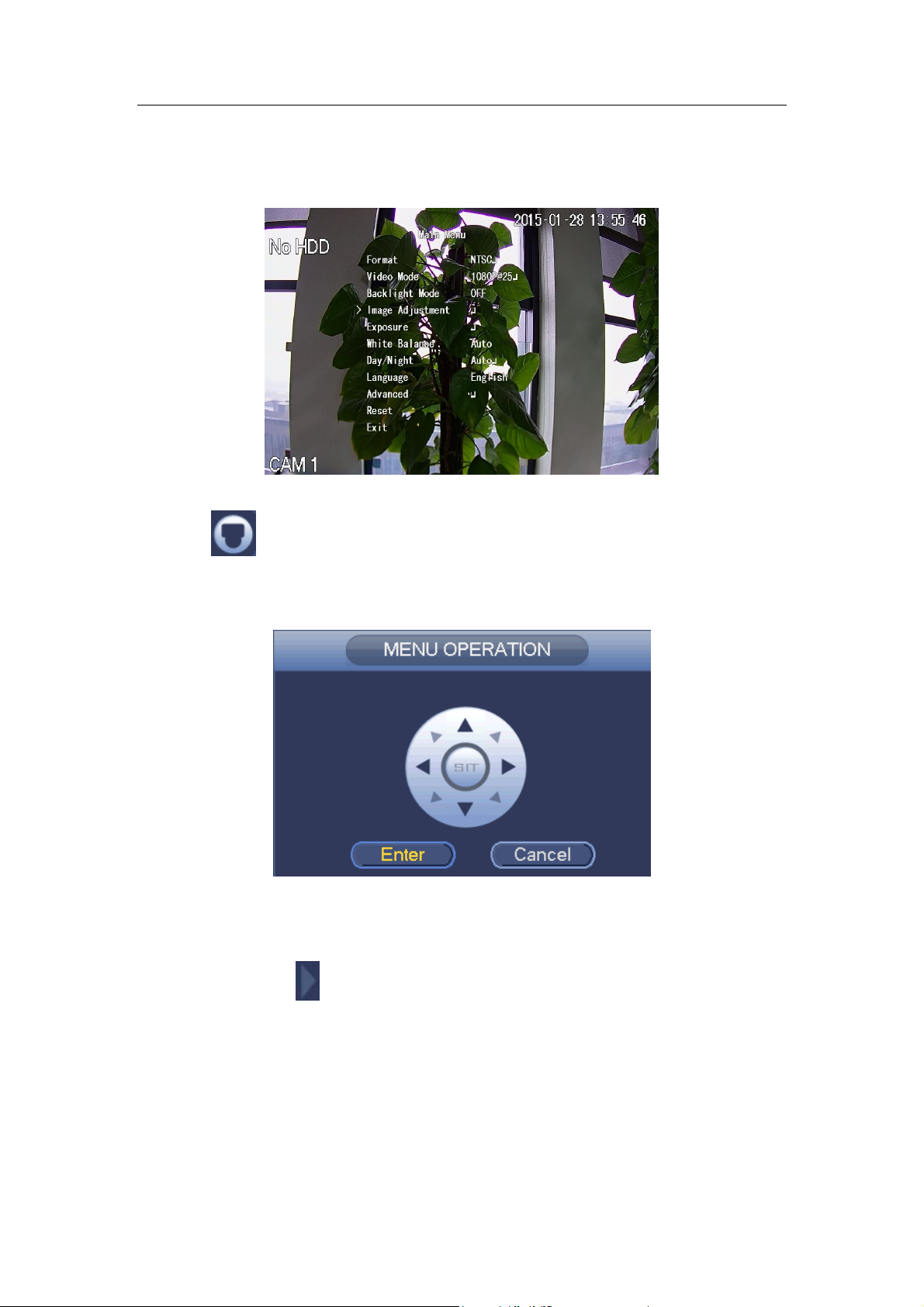
Standalone DVR User’s Manual
86
In Figure 4-24, there are two ways for you to call the menu and set.
a) Click “Iris +” to call the OSD menu of the HDCVI camera. See Figure 4-22. Use
direction buttons to select the parameters and click the “Iris +” to confirm.
Figure 4-22
b) Click , you can view menu operation interface. See Figure 4-23. Click the Enter
button, you can see the OSD menu of the HDCVI camera. See Figure 4-22. Use
direction buttons to select the parameters and click the “OK” to confirm.
Figure 4-23
4.5.3.2 PTZ Setup
In Figure 4-20, click to open the menu, you can set preset, tour, pattern, scan and
etc. See Figure 4-24.
Page 97
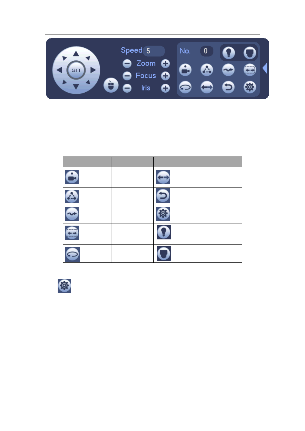
Standalone DVR User’s Manual
87
Icon
Function
Icon
Function
Preset
Flip
Tour
Reset
Pattern
Aux
Scan
Aux on-off
button
Rotate
Go to menu
Figure 4-24
Please refer to the following sheet for detailed information.
Please note the above interface may vary due to different protocols. The button is grey
and can not be selected once the current function is null.
Right click mouse or click the ESC button at the front panel to go back to the Figure
4-20.
4.5.3.3 PTZ Function Setup
Click , you can go to the following interface to set preset, tour, pattern, and scan. See
Figure 4-25.
Page 98
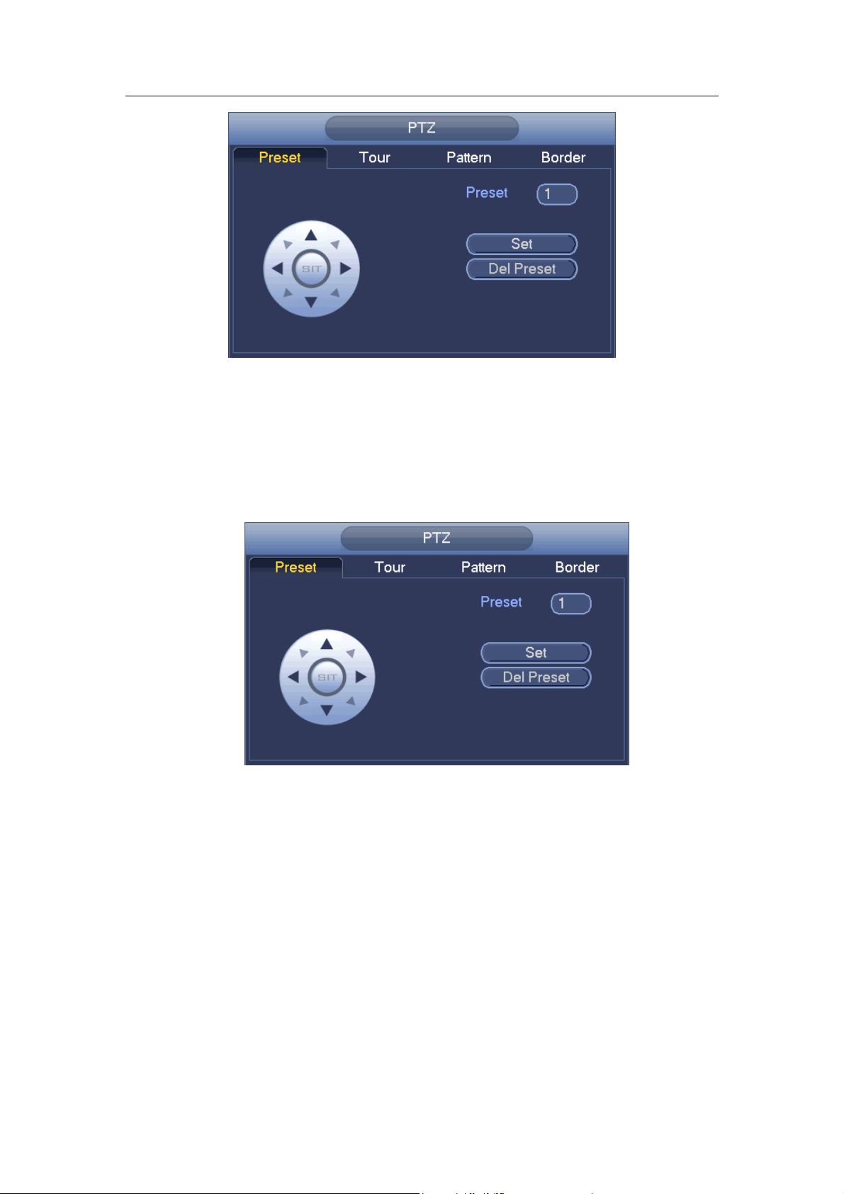
Standalone DVR User’s Manual
88
Figure 4-25
Preset Setup
In Figure 4-25, click preset button and use eight direction arrows to adjust camera to the
proper position. The interface is shown as in Figure 4-26.
Click Set button and then input preset number.
Click Set button to save current preset.
Figure 4-26
Tour Setup
In Figure 4-25, click tour button.
Input tour value and preset No. Click Add preset button to add current preset to the tour.
See Figure 4-27.
Tips
Repeat the above steps to add more presets to the tour. Click Del preset button to remove
it from the tour. Please note some protocols do not support delete preset function.
Page 99
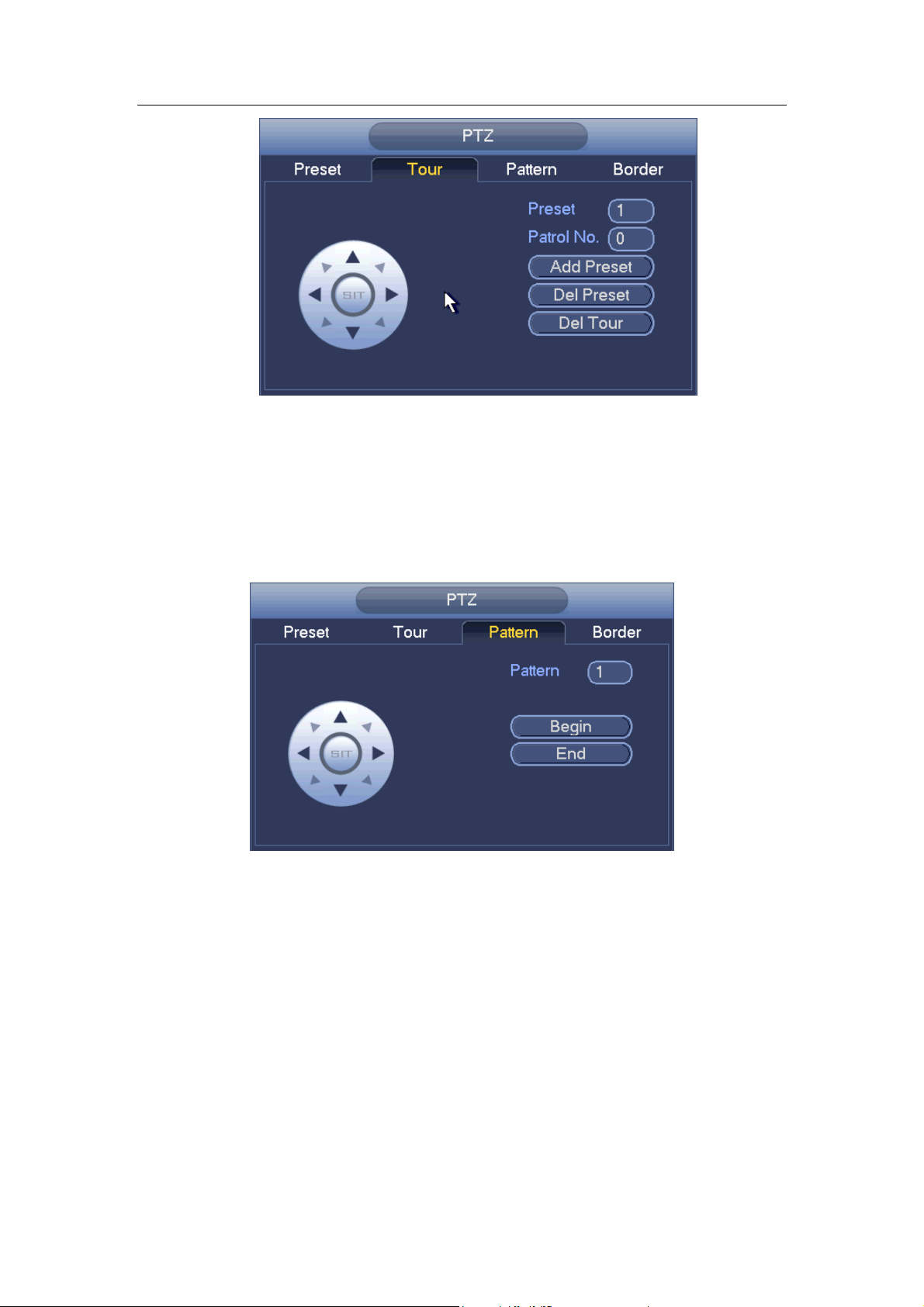
Standalone DVR User’s Manual
89
Figure 4-27
Pattern Setup
In Figure 4-25, click Pattern button and input pattern number.
Click Begin button to start direction operation. Or you can go back to Figure 4-20 to
operate zoom/focus/iris/direction operation.
In Figure 4-25, click End button.
Figure 4-28
Scan Setup
In Figure 4-25, click Scan button.
Use direction buttons to set camera left limit and then click Left button.
Use direction buttons to set camera right limit and then click Right button. Now the scan
setup process is complete.
Page 100

Standalone DVR User’s Manual
90
Figure 4-29
4.5.3.4 Call PTZ Function
Call Preset
In Figure 4-24, input preset value and then click to call a preset. Click
again to stop call.
Call Pattern
In Figure 4-24 , input pattern value and then click to call a pattern. Click
again to stop call.
Call Tour
In Figure 4-24, input tour value and then click to call a tour. Click again
to stop call.
Call Scan
In Figure 4-24, input Scan value and then click to call a tour. Click again
to stop call.
Rotate
In Figure 4-24, click to enable the camera to rotate.
System supports preset, tour, pattern, scan, rotate, light and etc function.
Note:
Preset, tour and pattern all need the value to be the control parameters. You can
define it as you require.
You need to refer to your camera user’s manual for Aux definition. In some cases, it
can be used for special process.
 Loading...