

Page 1
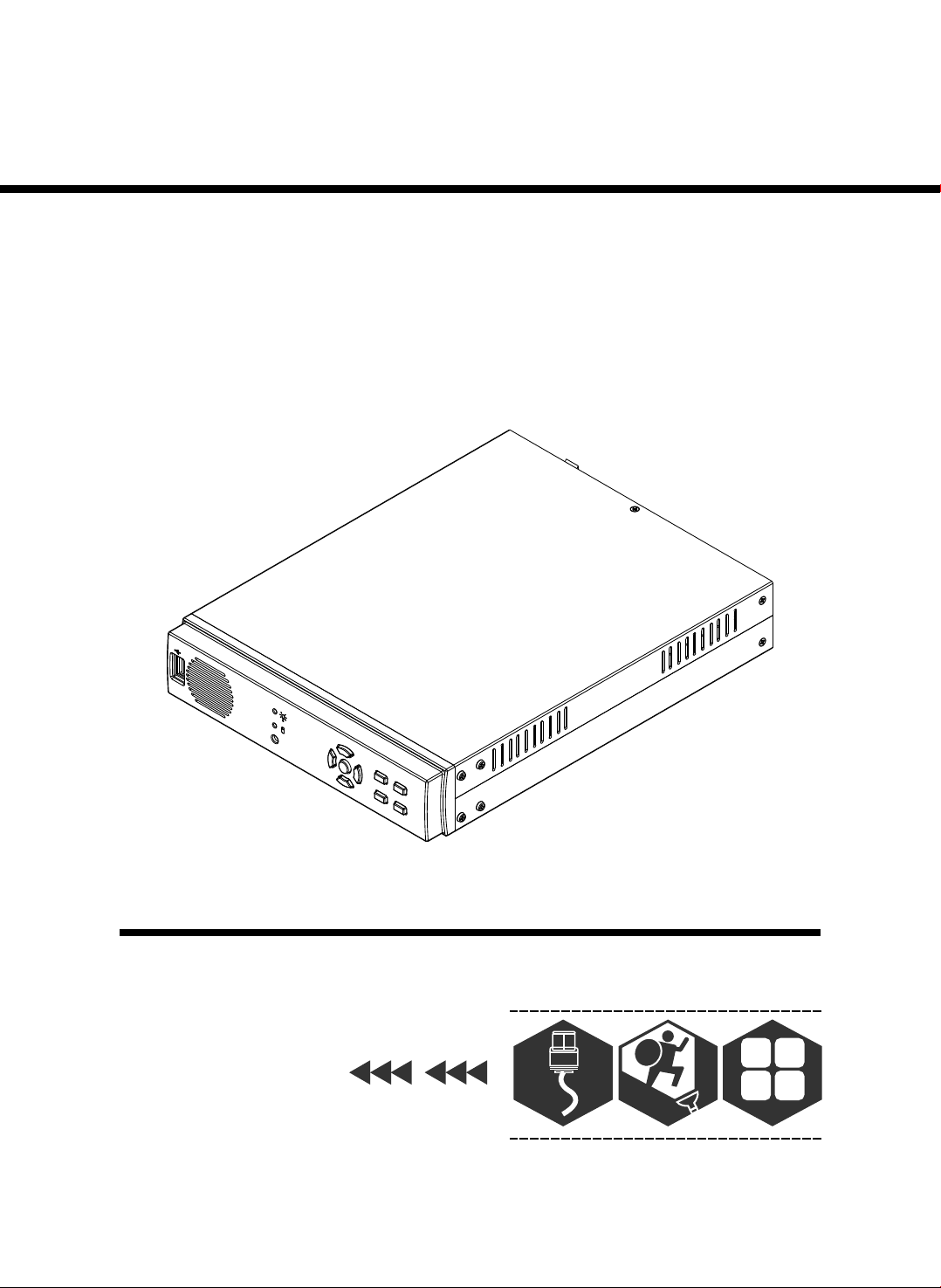
4 C H S TANDALONE DV R
U S ER M A N U A L
USB
20 08 J AN. Ver 1. 1
A
l
ar
m
1
4 CHANNEL
4
Page 2

Page 3
HDD SUPPORT LIST
Warning:
Should you wish to install a new hard
drive in this unit, a list of tested hard
drives shown to be compatible can be
found below.
4C H ST ANDAL ON E DV R
Brand
Samsung 80GB/ 160GB
IDE-
IDE-
Seagate 80GB/ 160GB/ 320GB/ 400GB
IDE-
Maxtor 80GB/ 160GB/ 320GB/ 400GB
SATA- Maxtor 160GB/ 250GB/ 320GB
SATA- Seagate 160GB/ 250GB/ 320GB/ 500GB/ 750GB
SATA- HITACHI 160GB/ 250GB/ 320GB/ 500GB/ 750GB
SATA- WD 320GB/ 500GB
Capacity
Warning:
The hard drive below is not recommended
for this unit
Brand Capacity
IDE- WD
SATA- WD 160GB/ 250GB/ 750GB/ 1TB
SATA- Maxtor 500GB
SATA- HITACHI 1TB
All Series
Page 4

4C H ST ANDAL ON E DV R
CONTENT
1、FEATURE
2、SPECIFICATIONS
3、INSTALLATION
4、FRONT PANEL
5、OPERATING MANUAL
6、VIEW CONTROL
7、PLAYBACK CONTROL
8、RECORD CONTROL
9、4 CHANNEL RECORDING HOURS
10、DVR Viewer User Guide
11、SATA TO PATA CONVERT BOARD(Option)
2
3
4
5
6
8
9
9
10
11
18
-1 -
Page 5

4C H ST ANDAL ON E DV R
1、FEATURE
1、Definitely Standalone.
2、Real Time Refresh Rate.
3、Display While Recording.
4、Frame Recording & Quad Recording.
5、Compatible of NTSC/PAL format.
6、Advanced MJPEG.
7、Manual / Motion / Programmed
Systems records automatically while alarming.
8、
9、Search by Time / Date.
10、Watch dog feature.
11、HDD Volume Indicator.
12、Can use USB to link PC, Player can search Time to Play、
saving and take photos functions.
13、Internal motion detect feature.
14、Remote Control.
15、Support Audio Recording.
-2 -
Page 6

2、SPECIFICATIONS
4C H ST ANDAL ON E DV R
OPERATION SYSTEM
Video Input
VGA Output
Video Input Channel
Video Output Channel
Display Frame
Recording Frame
Rate(QUAD)
Recording Frame
Rate(EACH)
Recording Mode
Resolution
Compression Format
HDD
Search
MOTION DETECT
LOSS DETECT
BUZZER OUTPUT
Brightness adjust
Contrast adjust
USB Output
VGA Output
System a monitor
Power supply
Dimension
Weight
Audio Function
Embedded RTOS
NTSC/PAL
D-SUB 15P VGA
4CH Composite
1CH Composite
NTSC 120 fps (4x30 fps)
PAL 100 fps (4x25 fps)
NTSC Max. 30 fps
PAL Ma x. 2 5 fp s
NTSC Max. 7. 5f ps (3 0 fp s/ 4)
PAL Max. 6.25fps(25 fps/ 4)
Continuous / Motion / Programm ed
Display NTSC 720x4 80
PA L 72 0 x 57 6
Recording NTSC 640x2 24
PA L 64 0x 27 2
Advanced Low 12K Byt es / F ra me
MJPEG Normal 15K B yt es / F ra me
High 20K Bytes / F ra me
400G X 1 (Max)
Mode
Full screen
Power recover auto restore rec or d mo de
DC 12V / 4A(AC110V-240V 50/60HZ)
220mm x 288mm x 48mm (W x D x H)
Audio Input/Output Real Line Recor di ng
Time / Date / Event
YES
YES
YES
YES
YES
YES
YES
YES
1.5KG
And Playing
-3 -
Page 7
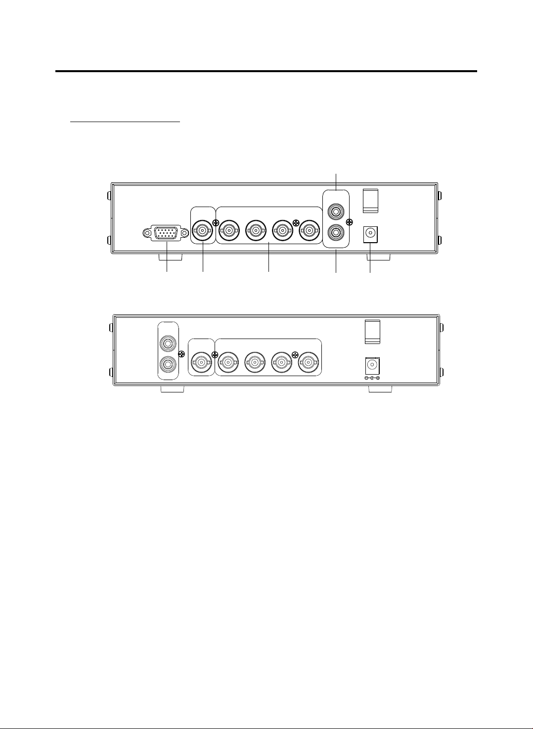
3、INSTALLATION
REAR PANEL
4C H ST ANDAL ON E DV R
REAR PANEL A
XGA
(1)
VIDEO OUT
(2)
REAR PANEL B
AUD IO
IN
VID EO OUT
OUT
XGA Output REAR PANEL
(1) (Only A)
VIDEO IN
(3)
VID EO IN
(4)
AUDIO
IN
CH4CH3CH2CH1
OUT
(5)
CH4CH3CH2CH1
DC12V
(6)
DC1 2V
(2) Video Output : Correspon ding to Video Input.
(3) Video IN : Cameras to Video In put.
(4) Audio Input.
(5) Audio Output.
(6) Power Input : Please use the p ower supply attached
Adaptor : DC-12 V / 4A
-4 -
Page 8
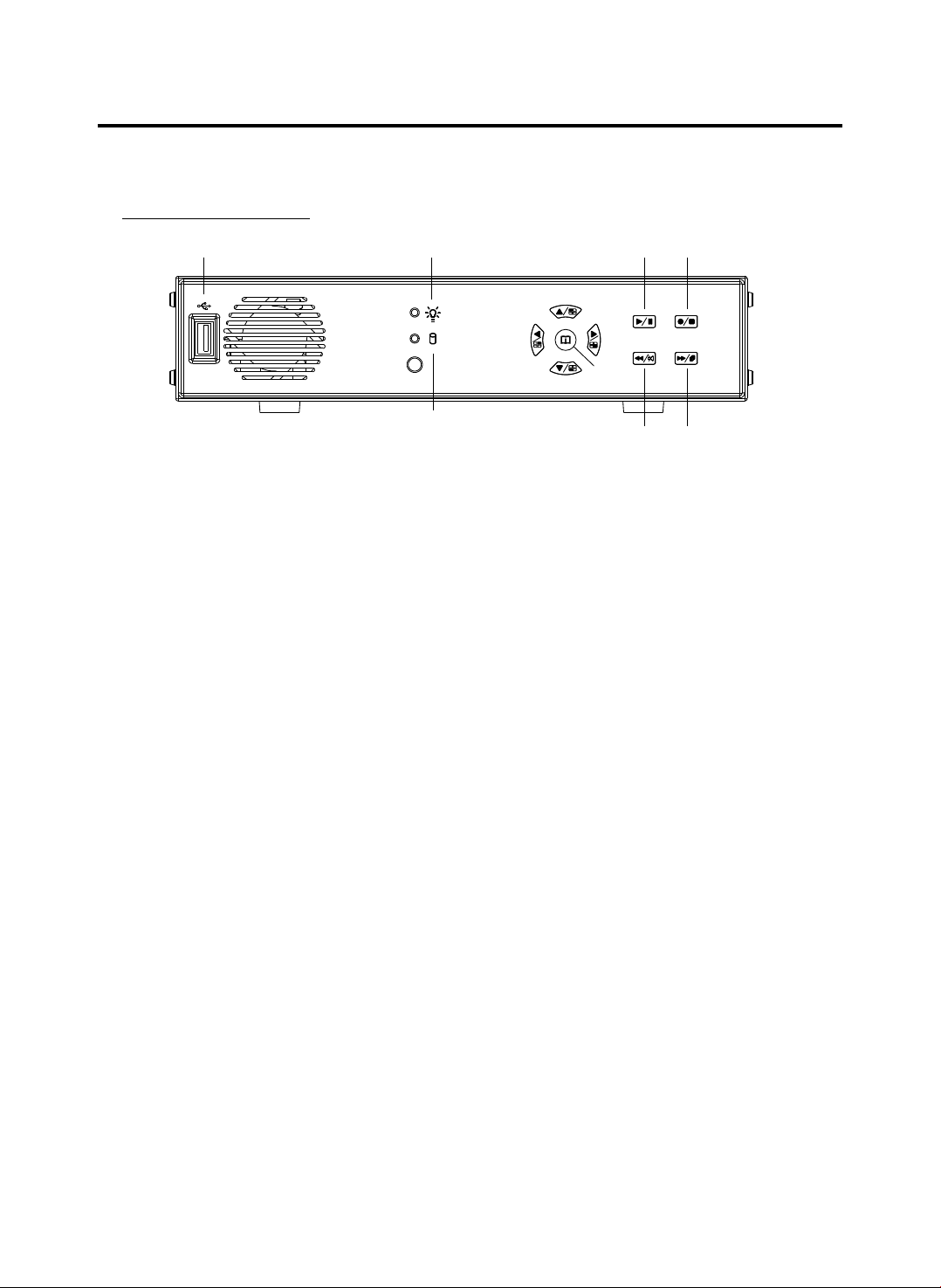
4、FRONT PANEL
(1)
4C H ST ANDAL ON E DV R
( 10)
( 2 )
( 9 )
( 4 )
( 6 )
( 7 )
( 8 )
(11) (12)
( 5 )
( 3 )
(1) USB PORT
(2) Record Indicator
(3) HDD Indicator
(4) Move Up / Camera 1 Display
(5) Move Left / Camera 2 Display
(6) Move Down / Camera 3 Display
(7) Move Right / Camera 4 Display / Select
(8) Menu / Show Percentage of th e hard Drive recorded
(9) Play / Pause
(10) Record / Stop
(11) Fast Reverse / Mute
(12) Fast Forward / Sequence Switch
-5 -
Page 9

4C H ST ANDAL ON E DV R
5、OPERATING MANUAL (MAIN MENU)
MAIN MENU
SYSTEM SE TU P
CAMERA SET UP
RECORD SE TU P
RECORD SC HE DULE
MOTION SE TU P
HARD DRIV E SE TUP
XGA RESOLU TI ON : 1024 X 768
SYSTEM RE STORE
( ) : SELECT ( ) : SET ( ) : EXI T
XGA RESOLU TI ON : 640X 480, 800X 600, 10 24 X768 ( ,1280X1 024. REAR PANELdefault s ettin g) (Only A)
Press to select items, use to enter.
Press to exit
SYSTEM SETUP
(Only A)REAR PANEL
SYSTEM SETU P
BUZZER ALA RM TIME : 2
LOSS ALARM : ON
AUDIO REC OR D :
AUDIO MUT E : ﹝OFF﹞
AUDIO INP UT V OLUME : 8
AUDIO OUT PU T VOLUME : 8
PASSWO RD SETUP
TIME SETU P
( ) : SELECT ( ) : SET ( ) : EXI T
﹝ ﹞
﹝OFF﹞
Press to select items, use to enter.
Press to exit
PASSWORD SETUP
Select this i tem to change p as sword :
CURRENT PASSWOR D :_ _____
NEW PASS WO RD :_____ _
CONFIRM PASSWORD :___ ___
(1) When th e ne w passwor d is a ccepted , you will rece ive a
message t ha t inform yo u. PASSW OR D CHANGED
(2) If the pa ss word was no t ac cepted, y ou will recei ve a
message t ha t inform yo u. NO PASS WO RD CHANGE D
*Use the view control button on the front panel to input the number.
-6 -
Page 10

4C H ST ANDAL ON E DV R
is:"1" is:" 2" is:"3" is: "4”
TIME SETUP
Select this i tem to set up cur re nt time.
TIME SET
2004/12/1 7 18:00:30
( ):S ELECT ( ): SET ( ): EX IT
Press to select items, use to enter.
Press to exit
CAMERA SETUP
CAMERA SETUP
CAMERA : CH 1
LIVE ON/OFF : O N
RECORD ON/O FF : ON
BRIGHT SE TUP : 5
CONTRAST SETUP : 5
COLORS SETU P : 5
AUTO SW IT CHING : 2
( ):S ELECT ( ): SET ( ): EX IT
Press to select items, use to enter.
Press to exit
RECORD SETUP
RECORD SETU P
RECORD MODE :E ACH
VIDEO QUALI TY :NORMAL
RECORD FRAM E RATE :30
( ):S ELECT ( ): SET ( ): EX IT
Press to select items, use to enter.
Press to exit
(1) Record Se tup:EACH MOD E (f rame record ing),
QUAD MODE (quad recording).
(2) Vid eo Q uality: vid eo quality se le ction: High , Normal, Low
(3) Record Fr ame Rate: QUA D MO DE frame rate a lternativ es a s follows :
Enable Audio Record → 30、15、10、7、5、4 fps.
Disable Audio Record → 30、15、10、7、5、4、3、2、1 fps.
Each Mode frame rate alternatives as follows:
Maximum : 7.5 fps each camera Totally :30 fps = 7.5 x 4 CH
In this mode 、 、 、 invalid.
-7 -
Page 11

4C H ST ANDAL ON E DV R
RECORD SCHEDULE
TTTTTTTTT TTTTTTTTT TT TTTT
: : : : : : : :
0 3 6 9 12 15 18 21
RECORD SCHE DULE
Press to select items, use to enter.
Press to exit
(1)Range: 0 -24 hrs.
(2)Set ”T” fo r continuou s re cording.
(3)Set “M” fo r motion reco rd ing.
(4)Set up ”-” t o disable the r ec ording.
MOTION SETUP
MOTION SE TU P MENU
CHANNEL-1 S ENSITIVIT Y 0 (OFF)
CHANNEL-2 S ENSITIVIT Y 0 (OFF)
CHANNEL-3 S ENSITIVIT Y 3 .
CHANNEL-4 S ENSITIVIT Y 5 .
( ):S ELECT ( ): SET ( ): EX IT
Press to select items, use to enter.
Press to exit
If you want to enable Motion Rec ording,
★ Please finish
the setup procedure a. and b.
a. Set S ENSITIVITY in t he menu option
“MOT ION SETUP MENU"
b. Set “ PROGRAMMED RECORD” - -- “M” in the menu
6、VIEW CONTROL
(1)You can use the following view control buttons to monitor the video from the cameras.
Camera #1 (Ch1), return to Q ua d Mo de b y pr es s ag ai n.
Camera #2 (Ch2),return to Qu ad M od e by p re ss a ga in .
Camera #3 (Ch3),return to Qu ad M od e by p re ss a ga in .
Camera #4 (Ch4),return to Qu ad M od e by p re ss a ga in .
(2)View Control is only valid while the RECORD MODE is in the EACH M OD E.
QUAD Display, Enable / Disable theAuto switching function.
option “RECORD SCHEDULE”.
-8 -
Page 12

7、PLAYBACK CONTROL
(1)Press , and the system will play the latest event which you haven't seen before.
(2)Press , and the system will enter the PLAYBACK EVENTS SE ARCH MODE.
(3)Each period is as four hour.
4C H ST ANDAL ON E DV R
SEARCH TI ME
HARD DRIVE : MA STER
04/04/01 02 :47:56 - 04/0 4/ 01 02:47:56
01 TIME 2 00 4/12/10 02: 47:50
02 TIME 2 00 4/12/10 02: 47:50
03 TIME 2 00 4/12/10 02: 47:50
Selec t Start Date/
Time to End Date/
Time
Press to select items, use to enter.
Press to exit, se lect event / time.
Press to swit ch between th e TIME SEAR CH M ODE and the P LAYBACK
EVENTS SEAR CH MODE,
Press to exit .
(1)EVENTS SEARCH MODE :
Press cho ose one period, then press to play.
(2)TIME S EARCH MODE :
The signal > goes up to the HARD DRIVER: MASTER. Press
to select i tems. Use select to change data, Then press
to play.
(3)PLAYBACK :
*Press to speed forwar d. C on ti nu e to p re ss a nd s ho w
X2, X4, X8 , playing.
*Press to rewind the pla yb ac k.
*Press to pause.
*Press to stop.
8、RECORD CONTROL
(1)Press t o start recor ding.
(2) Durin g recording , the mark * appears in status of overwriti ng
-9 -
Page 13

4C H ST ANDAL ON E DV R
9、4CH RECORDING HOURS ON 80GB HARD DRIVE
*Thereinafte r a ro ug h es ti ma te a t ab le f or r eference only, reco rd in g da ta
quantity can follo w an i ma ge a v ar ia ti on a r at e somewhat diffe re nt .
Recordi ng Re sult s in NT SC For mat
Vid eo
Signa l
NTSC
Displ ay
Forma t
QUAD
MOD E
EACH MOD E
(Full Sc reen )
Vid eo
Quali ty
High
Nor mal
Bas ic
High
Nor mal
Bas ic
Recordi ng Re sult s in PAL Format
Vid eo
Signa l
PAL
Displ ay
Forma t
QUAD
MOD E
EACH MOD E
(Full Sc reen )
Vid eo
Quali ty
High
Nor mal
Bas ic
High
Nor mal
Bas ic
30 fps 15 fps 7 f ps 1 fps
36Hours 72 Hours 144 Hours 1,080 Hours
48 Hours 96 Hours 192 Hours 1,4 40 Hours
58 Hours 116 Hours 232 Hours 1,740 Hours
64 Hours 128 Hours 256 Hours 1,920 Hours
90 Hours 180 Hours 360 Hours 2,700 Hours
112 Hours 224 Hours 448 Hours 3,360 Hours
25 fps 12 f ps 6 fps 1 fp s
38 Ho ur s 76 Ho ur s 152 Hou rs 95 0 Ho urs
48 Ho ur s 96 Ho ur s 192 Hou rs 1, 20 0 Hou rs
60 Ho ur s 120 Hou rs 240 Ho urs 1 ,5 00 Ho urs
62 Ho ur s 124 Hou rs 248 Ho urs 1 ,5 50 Ho urs
90 Ho ur s 180 Hou rs 360 Ho urs 2 ,2 50 Ho urs
118 Ho ur s 236 Ho urs 47 2 Hours 2 ,950 Ho urs
-1 0-
Page 14

4C H ST ANDAL ON E DV R
10、DVR PC Viewer User Guide
Introduction
Th is doc ument is the Op erati on Man ua l fo r t he 4 CH Stand A lon e D VR PCVie wer.
Th e appl icati on wil l s how yo u stre am ima ge store d in th e S tor ag e Devi ce (HD D, CF c ar d,
US B Memo ry Sti ck , et c. ), whi ch was pr evi ou sly fo rmatt ed and re corde d by th e D VR.
If an y D VR -f ormatted Storage De vi ce is co nn ec ted to your PC, the ap pl ic at io n w il l
au to ma ti ca lly detect the Stora ge De vi ce an d s how the recorded strea m. Yo u c an al so
sa ve th e c ur re nt screen to a JPEG fi le , a nd sa ve th e video/audio strea m t o a fi le
[MY S f il e, th e Vineyard's propri et ar y v id eo /a udio stream file for ma t.
Th e ap pli cat ion con sis ts of t wo f unc tio nal mo d ul es:
D VR P C Vi ewe r S how s st rea m st ore d i n th e DV R St ora ge D evi ce .
M YS F ile Pla yer Pla ys c ap tur ed s tre am f ile .
Terms in Thi s Document
Storage Device
The Application
DVR Storage Device Storage Device which was previously formatted and recorded by the
DVR base on Vineyard Technologies' DVR chip.
OS
CPU
RAM
GUI
Hard Disk, CF Card, USB Memory Stick
DVR Storage Device PC Viewer
Operating System
Central Processing Unit
Random Access Memory
Graphic User Interface
Requirement
OS
DirectX
OS of your PC should be Windows 2000(SP4) / XP(SP2) or later.
Your PC should be equipped with DirectX 7.0 or later.
Recommendation
Operating System (OS)
CPU
RAM
The application runs only on Windows 2000 (SP4) / XP (SP2) or later
1.0 GHz or Higher.
256 MByte or greater.
Installation
A. Hardware Installation
Before executing the application, connect the DVR Storage Device to the IDE cable of your
PC directly, or via USB adaptor
B. Software Installation
Run Setup.exe in the CD-ROM and follow the instruction to finish the installation.
[Make sure that the OS of your PC is Windows 2000 SP4/Windows XP SP2 or later.
- 11 -
Page 15

4C H ST ANDAL ON E DV R
Execution
Just d ouble click the icon of PC Viewer. The application will try to detect physical storage devices
installed at you r PC an d sea rch for DVR storage device(s) amo ng the m.
If the re is DVR Storage Device , the application will autom atica lly st art playing . However, If t he
application fails to de tect D VR Storage Device, whi ch means tha t there is no DVR St orage
Device installed to your syst em, it will show follow ing er ror me ssage and se t the default working
mode to MYS P layer (See Section. 4).
OK
Fig.1. No DVR Storage Device Message
Shortcut to play the video files on your PC via the attached
USB cable:
a. Connect US B cable both en ds t o the USB port of t he DVR and your P C.
b. Supply 12V DC power to the D VR .
c. Wa it until the me ss age of USB de te cted pops up on t he V GA monitor.
d. Run the PC Viewer softw are accordi ng ly.
e. Wa it until the ve ry f irst imag e co mes up to the PC Viewer.
f. Click “Pla y” icon on the co nt rol panel of th e PC View er t o start
viewing the v ideo files.
DVR PC Viewer
A. User Interface
The default page of the application is DVR Storage Device PC Viewer. The user interface is
shown in Fig.2.
- 21 -
Page 16

(1)
4C H ST ANDAL ON E DV R
(12)
(2)
(3)
(4) (5) (6) (7 ) (8) (9) (10)
Screen
(1)
(2)
Positioning Slider Bar
(3)
MYS Player Button
(4)
DVR Storage Device Change Button
(5)
DVR Storage Device Information
(6)
Channel Selection
(7)
PC Viewer Playback Control
(8)
Capture Stream Button [MYS]
Screen Capture Button [JPEG]
(9)
Audio Control
(10)
Viewer Playback Mode
(11)
Stream Time Display
(12)
(11)
Fig.2. DVR Storage Device PC Viewer User Interface
B. Functions
i. MYS Player Button
If you want to see MYS file which was stored in your PC, press this button or press [F2] key.
ii. DVR Storage Device Change Button
When there are more than one DVR storage devices, this button will be activated. Press this
button when you want to see video/audio stream stored in other DVR storage device. Fig.3
shows DVR storage device selection window.
Fig.3. DVR Storage Device Selection Window
- 31 -
Page 17

4C H ST ANDAL ON E DV R
iii. DVR Storage Device Information Button
If you want to know how big is the DVR storage device is, or how much stream data is stored
in the device, press this button. Fig.4 shows the DVR storage device information window.
Fig.4. DVR Storage Device Information Window
iv. Channel Selection Buttons
According to the record channel setting of the stream, each channel buttons will be enabled.
Select any channel you want to see enlarged.
Fig.5. Channel Selection Buttons
Press button (or [ 5 or Numpad 5 ] Key) to see all 4 channels at the same time.
Press button (or [ 1 or Numpad 1 ] Key) to see channel 1 enlarged.
Press button (or [ 2 or Numpad 2 ] Key) to see channel 2 enlarged.
Press button (or [ 3 or Numpad 3 ] Key) to see channel 3 enlarged
Press button (or [ 4 or Numpad 4 ] Key) to see channel 4 enlarged.
v. Viewer Control Buttons
Use Viewer Control Buttons to control viewer playback.
Fig.6. Viewer Control Buttons
*Press button (or [<-] Key) to start fast reverse playback. By pressing this button again,
you can adjust the speed. The maximum speed is 8 times faster than reverse playback.
*Press button (or [<-] Key) to start reverse playback.
*Press button (or [Space Bar]) to pause playback.
*Press button (or [->] Key) to start normal playback.
*Press button (or [->] Key) to start fast forward playback. By pressing this button several
times, you can adjust the speed. The maximum speed is 8 times faster than normal playback.
- 41 -
Page 18

4C H ST ANDAL ON E DV R
vi. Capture Stream Button
If you want to capture stream, follow the stream capture procedure listed below:
* Using Positioning Slider Bar find the stream position you want.
* Make sure that the playback is in PAUSE mode, and the Capture Stream Button is enabled.
* Press the button, then the application will start capturing. During capturing, Capturing
Indicator Window will be popped up.
Fig.7. Capturing Indicator Window
To stop capturing, press Stop Capturing button on the window.
*
The captured file (an MYS file) will be stored in the Capture Directory. See the Application
Setting Section, to know more about the Capture Directory setting.
vii. Screen Capture Button
If you wan to capture the screen, follow the screen capture procedure listed below:
* Using Positioning Slider Bar find the stream position you want.
* Make sure that the playback is in PAUSE mode, and the Screen Capture Button is enabled.
* Press the button, then the application will start to make a JPEG file. When a JPEG file
successfully created. The application let you know that the image file is created showing
the file name and the Capture Directory path.
viii. Audio Control
Fig.8. Audio Control Buttons
Press button to enable sound. Once sound is enabled, the button icon will be changed to
. Press it to disable sound again. Using the slider bar, you can adjust the volume.
MYS Player
A. User Interface
Fig. 9 shows the user interface of the MYS player.
- 51 -
Page 19

(1)
4C H ST ANDAL ON E DV R
(2)
(3)
(4) (5)
Screen
(1)
MYS File Select Dialog
(2)
Positioning Slider Bar
(3)
PC Viewer Button
(4)
File Open Button
(5)
(6)
(7)
MYS file information
(6)
MYS File Playback Control
(7)
Screen Capture Button [JPEG]
(8)
Audio Control
(9)
Playback Status
(10)
(8)
(9)
(10)
Fig.9. MYS File Player User Interface
B. Functions
i. PC Viewer Button
When you want to back to PC Viewer function, press this button.
ii. File Open Button
Press this button to select MYS file.
iii. MYS file information
When an MYS file selected and being played, the file name and the file size will be displayed
in the MYS file information box.
iv. MYS file Playback Control Buttons
Use MYS file playback buttons to control the playback.
Fig.10. MYS file playback control Buttons
- 61 -
Page 20

4C H ST ANDAL ON E DV R
* Press button (or [<-] Key) to start fast reverse playback. By pressing this button again,
you can adjust the speed. The maximum speed is 64 times faster than reverse playback.
* Press button (or [<-] Key) to start reverse playback.
* Press button (or [Space Bar]) to pause playback.
* Press button (or [->] Key) to start normal playback.
* Press button (or [->] Key) to start fast forward playback. By pressing this button several
times, you can adjust the speed. The maximum speed is 64 times faster than normal playback.
v. Screen Capture Button
If you wan to capture the screen, follow the screen capture procedure listed below:
* Using Positioning Slider Bar find the stream position you want.
* Make sure that the playback is in PAUSE mode, and the Screen Capture Button is enabled.
* Press the button, then the application will start to make a JPEG file. When a JPEG file
successfully created. The application let you know that the image file is created showing the
file name and the Capture Directory path.
vi. Audio Control
Fig.11. Audio Control Buttons
Press button to enable sound. Once sound is enabled, the button icon will be changed to
. Press it to disable sound again. Using the slider bar, you can adjust the volume.
■ Application Setting
A. User Interface
Enable/Disable
Application Closing
Confirm
Change
Captured
File Saving
Directory
Fig.12. Application Setting Dialog
B. Functions
i. Capture Directory
You can specify Capture Directory. To change the path, press Change Button, select
directory you want, and press OK again.
ii. Message Box
You can enable/disable the application close confirm message box.
- 71 -
Page 21

4C H ST ANDAL ON E DV R
11、SATA TO PATA CONVERT BOARD
(Option)
Foreword
This is a S ATA conve rt PATA interf ace PCB b oa rd,
befor e us ing the p roduc t, plea se read t hi s manua l
caref ul ly for fu rther r ecogn izing f or t he prod uct!
I. Key Featur e
Conve rt S ATA TO PATA inter face
Tra nsfer r ate max u p to 6 6/100 /133M B/sec
No SATA HDD c ap acity l imite d
LED ind ic ators f or Powe r(gre en) & HDD (r ed)
Compa ct J BOD ( Big ) s pecia l funct ion.
II. Hardwar e an d Install
SATA HDD
80pin PATA cab le
4pin po wer c abl e
Power L ED
HDD LED
Jumpe r sel ect
Dev ice 0=M aster ( Jumpe r off)
Dev ice 1=S lave (J umper o n)
22pin S ATA con necto r
4pin po wer c abl e
40pin PATA con nec tor
4pin po wer
conne cto r
Maste r SATA HDD
To Mas ter SATA HDD
Jumpe r off
Slave S ATA HDD
III. Jumper s et ting for Mast er & S lave
1. One PATA cabl e wi th one SATA HDD t he n Jumpe r
setti ng i n Maste r ( Jumpe r off )
2. One PATA cabl e wi th two SATA HDD t he n Jumpe r
setti ng i n one is Ma ster ( Ju mper of f ); and an other i s
Slave ( J um per on ).
3. Usin g JB OD ( Big ) sp ecial f uncti on.
a.) One PATA cab le w ith two S ATA HDD the n Jumpe r
setti ng s ame as st ep 2.
b.) Two PATA cable , each ca bl e with on e SATA HDD
then th es e two Jum pers al ways se tting i n Ma ster
( Jumpe r off )
To Sla ve SATA HDD
Jumpe r on
4pin po wer c abl e
- 81 -
Page 22

4C H ST ANDAL ON E DV R
One PATA c able wi th one SATA HDD,
Jumpe r set to Ma ster ( Ju mp er of f )
One PATA c able wi th two SATA HDD,
Jumpe r one set t o Maste r ( Ju mpe r off
); anot her set t o Slave (J ump er o n)
Using JBOD ( Bi g ) special fun ct ion
One PATA c able wi th two SATA HDD, Ju mper on e set to Ma ster ( Ju mper of f ); anot her set t o
Slave (Jump er on)
Each on e PATA cable w ith one S ATA HDD, Ju mper al l set to Ma ster ( Ju mper of f )
- 91 -
Page 23

Page 24

 Loading...