

Page 1
USER MANUAL
4CH STANDALONE DVR
20 05 JU NE
Page 2

Page 3
4CH STA NDALONE DV R
-1 -
CONTENT
1、FEATURE
2、SPECIFICATIONS
3、INSTALLATION
4、FRONT PANEL
5、OPERATING MANUAL
6、VIEW CONTROL
7、PLAYBACK CONTROL
8、RECORD CONTROL
9、NTSC/PAL SETUP
10、Keypad Lock-up Setup
11、4 CHANNEL RECORDING HOURS
12、DVR Viewer User Guide
13、Video Server Board Installation、 (Option)
14
SXGA CARD FOR DVR USER MANUAL (Option)
2
3
4
5
6
11
11
12
12
12
12
14
19
25
Page 4

4CH STA NDALONE DV R
1、Definitely Standalone.
2、Real Time Refresh Rate.
3、Display While Recording.
4、Frame Recording & Quad Recording.
5、Compatible of NTSC/PAL format.
6、Advanced MJPEG.
7、Manual / Motion / Programmed / Sensor Recording.
8、4 Sensor by Time / Date.
9、Search by Time / Date.
10、Watch dog feature.
11、HDD Volume Indicator.
12、Can use USB to link PC, Player can search Time to Play、
saving and take photos functions.
13、Internal motion detect feature.
14、Auto switching function.
15、Looping Output.
16. Keypad Lock-up function.
1、FEATURE
-2 -
Page 5

4CH STA NDALONE DV R
2、SPECIFICATIONS
OPERATI ON SYSTEM
Video Input
Video Input Channel
Video Output Channel
Display Frame
Recording Frame
Rate(QUAD)
Recording Frame
Rate(EACH)
Recording Mode
Resolution
Compression Format
HDD
Backup Device
Search
Sensor
MOTION DE TECT
LOSS DETECT
BUZZER OUTPUT
Brightness adjust
Contrast adjust
USB Outpu t
Looping Output
Keypad Lock-up
System a mo nitor
Power supply
Dimension
Weight
LAN
AUTO SWIT CHING
Embedded RTOS
NTSC/PAL
4CH Composite
2CH Composite (VCR OUT / MONITOR OUT)
400G X 2 (Max )
VCR
Time / Date / E vent
YES
4 Input / 1 Out put
YES
YES
YES
YES
YES
YES
YES
YES
YES
Power recover auto restore record mo de
DC 12V / 4A(A C110V-240V 50/60HZ)
430mm x 300mm x 48mm (W x D x H)
3.5KG
10/100M
NTSC
PAL
NTSC Max
PAL Max.
NTSC M x. 7.5fps (30 fps/4)
PAL Max. 6.25f ps(25 fps/4)
Motion Sensor
P L 720 x 576
Mode
Full screen
120 fps (4x 30 fps)
100 fps (4x 25 fps)
. 30 fps
25 fps
a
Continuous / / Program med/
Display NTSC 720x 480
A
Recording NTSC 640x224
PAL 640x272
Advanced Low 12K Bytes / Frame
MJPEG Normal 15 K Bytes / Frame
High 20K By tes / Frame
-3 -
Page 6
4CH STA NDALONE DV R
3、INSTALLATION
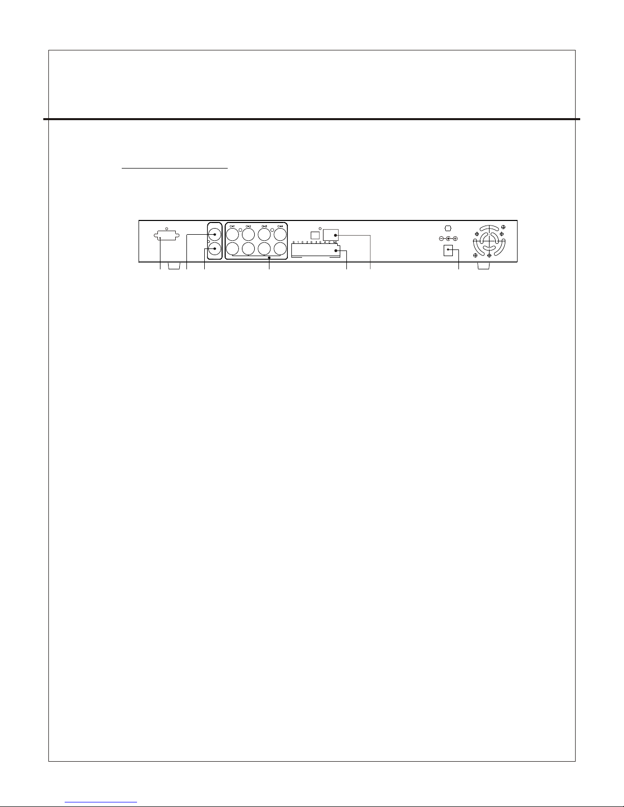
REAR PANEL
(1) Cameras Video Input and Looping Output.
(2) Video Output : Corresponding to Monitor Video Input.
(3) Video Output : Corresponding to VCR Video Input.
(4) Sensor I / O:
1、Sensor Input of Camera #1
2、Sensor GND of Camera #1
3、Sensor Input of Camera #2
4、Sensor GND of Camera #2
5、Sensor Input of Camera #3
6、Sensor GND of Camera #3
7、Sensor Input of Camera #4
8、Sensor GND of Camera #4
9、Relay COM Output
10、Relay N/O Output
(5)Power Input : Please use the power supply attached
Adaptor : DC-12V / 4A
(6) VGA Output : Connect to VGA Monter (option)
(7)Ethernet RJ-45 (option)
-4 -
MONITOR
VCR
VIDEO
LOOP OUT
LAN
IP
INIT
IN ALARM OUT
DC 12V
VGA
(1)(2)(3) (4) (5)(7)
(6)
Page 7

4CH STA NDALONE DV R
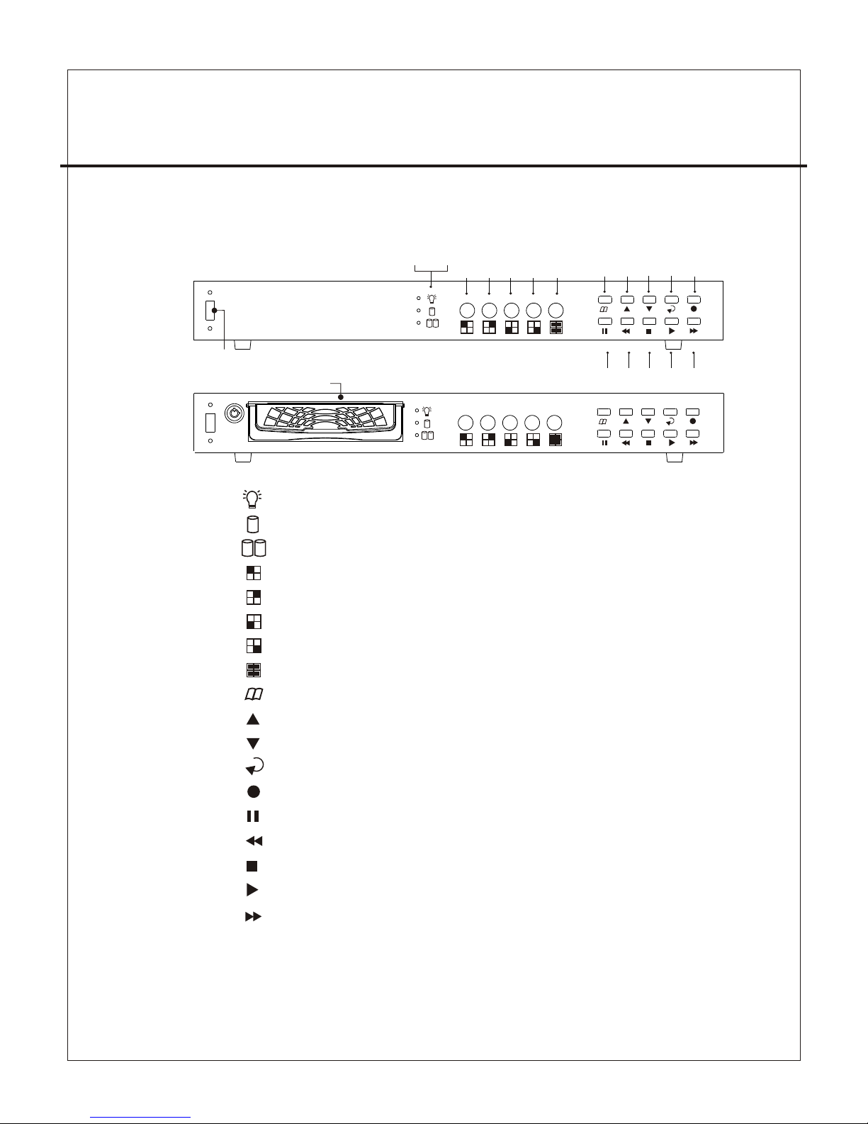
4、FRONT PANEL
(1) Recor d Indicator
(2) HDD #1 In dicator
(3) HDD #2 In dicator
(4) Camer a #1 Display (Ch1)
(5) Camer a #2 Display (Ch2)
(6) Camer a #3 Display (Ch3)
(7) Camer a #4 Display (Ch4)
(8) Quad Di splay (QUAD)
(9) MENU,
(10) UP
(11) DOWN
(12) SELE CT
(13) RECO RD
(14) PAUS E, Keypad Lock-up
(15) RF
(16) STOP
(17) PLAY
(18) FF
(19) USB Po rt
(20) HDD RA CK (TYPE B)
、AUTO SWIT CHING
Percent age of the Hard Drive recorde d
-5 -
(1) ( 2) (3)
(4) ( 5) (6 ) (7) (8)
(9) ( 10) (11) (1 2) (13)
(14 ) (15) (1 6) (17) ( 18)
(19 )
USB
TYPE B
TYPE A
USB
(20 )
Page 8
4CH STA NDALONE DV R
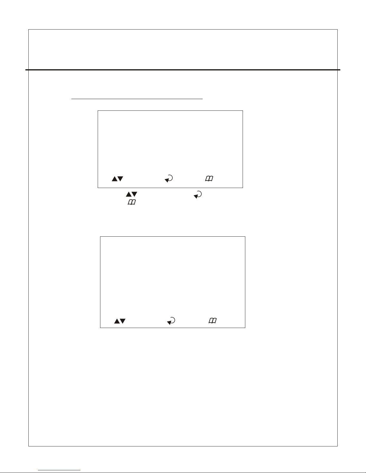
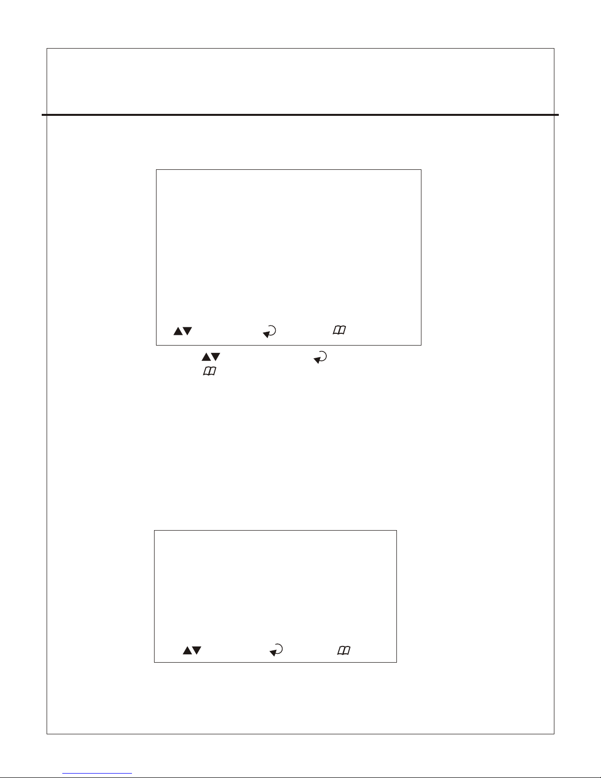
5、OPERATING MANUAL(MAIN MENU)
MAIN MENU
SYSTEM SETUP
CAMERA SETUP
RECORD SETUP
RECORD SCHEDULE
HARD DRIVE SETUP
SYSTEM RESTORE
( ):SELECT ( ): SET ( ):EXIT
Press to select items, use to enter.
Press to exit
5-1 、SYSTEM SETUP
SYSTEM SETUP
BUZZER ALARM TIME :02 S
SENSOR ALARM TIME :05 S
LOSS ALARM :ON
MOTION ALARM :ON-OFF
SENSOR ALARM :ON
PASSWORD SETUP
TIME SETUP
( ):SELECT ( ): SET ( ):EXIT
(1)Buzzer Alarm Time Setup: 1-30 sec.
(2)Sensor Alarm Time Setup: 0-30 sec, CONT (Continue).
(3)Loss, Motion, Sensor Alarm:ON/OFF.
(4) Motion Alarm:ON-O FF(4 Type) ,front is Alarm, behind
is jump to alarm a picture.
-6 -
Page 9

4CH STA NDALONE DV R
5-1-1 、PASSWORD SETUP
Select this item to change password :
OLD PASSW ORD :_ _ ____
NEW PASSW ORD :_ _ ____
PASSWOR D CONFIRM : _ ___ _ _
(1) When the new password is accepted, the board will flash the
following screen message.
“ PASSWORD CHANGING ”
(2) If the password was n ot accepted, you will receive a message
that inform you.
“ INCORRECT ”
*Use the view control button on the front panel to input
the umber.
is:"1" is:"2" is:"3" is: "4" is: " 5"
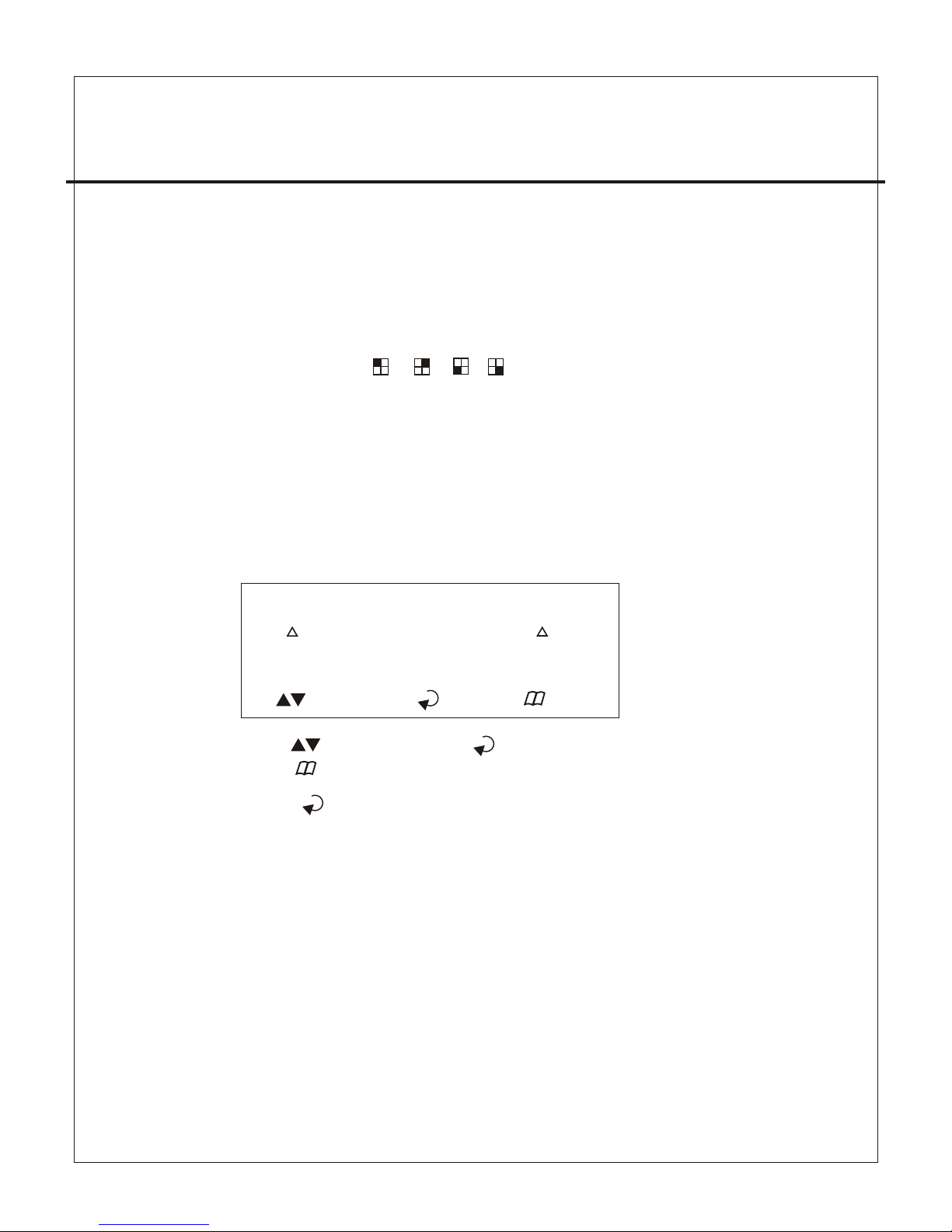
5-1-2 、TIME SETUP
Select this item to set up current time.
TIME SET
2004/12/17 18:00:30
SHOW : UP 1
( ):SELECT ( ): SET ( ):EXIT
*Press to setup time. Use to increase value.
Press to exit and to save data.
Show Time setup:
UP 1 : Displayed on up-right corner of screen, date & time listed
in a rows.
UP 2 : Displayed on up-right corner of screen, date & time listed
in two rows.
DOWN1 : Displayed on down-right corner of scre en, date & time
listed in a rows.
DOWN2 : Displayed on down-right corner of scre en, date & time
listed in two rows.
-7 -
Page 10
4CH STA NDALONE DV R
5-2 、CAMERA SETUP
CAMERA SETUP
CAMERA :CH1
RECORD SETUP :ON
BRI SETUP :05
CON SETUP :05
SENSOR SETUP :N-O
MOTION SETUP :ON
SENSITIVITY SETUP :0 5
( ):SELECT ( ): SET ( ):EXIT
AUTO SWITCHING :05 S
Press to select items . Use to change data.
Press to exit and to save data.
(1)Camera select (default value Ch1).
(2)Record Set up : yes or n o record.
(3)Brightness / Contrast Set up : default value is 5.
(4)Sensor Setup: Three items, N-O (normal-open),
N-C(normal-close), ----(not installed).
(5)Motion Set up : motion detector, ON/OFF.
(6)Sensitivity Set up : sensitivity setup of motion detector.
(7) AUTO SWITCHING : Switching time set up.
5-3 、RECORD SETUP
RECORD SET
RECORD SETUP :EACH MODE
VIDEO QUALITY :NORMAL
RECORD FRAME RATE :30 fps
SENSOR REC. FRAME RATE :15 fps
SENSOR RECORD TIME :05 S EC
( ):SELECT ( ): SET ( ):EXIT
-8 -
Page 11
4CH STA NDALONE DV R
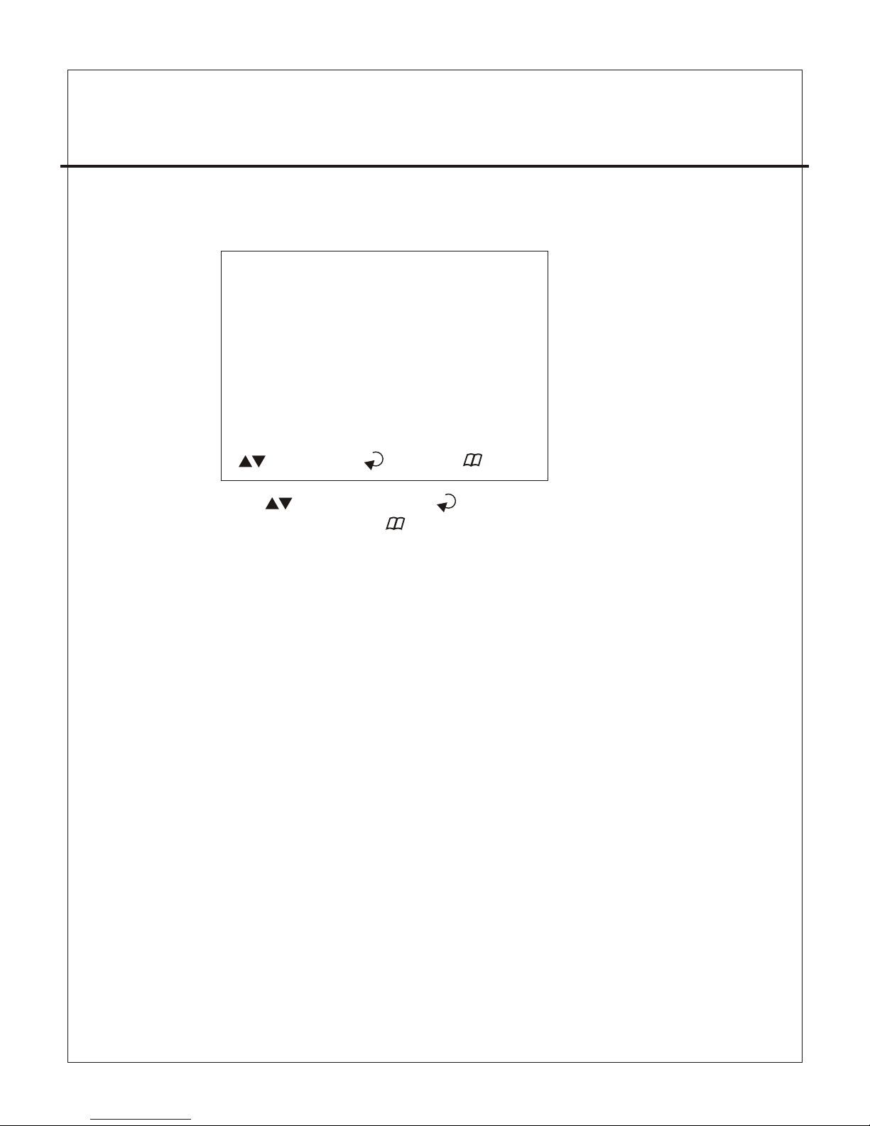
5-4 、RECORD SCHEDULE
RECORD SCHEDULE
TTTTTTTTTTTTTTTTTTTTTTTT
: : : : : : : :
0 3 6 9 12 15 18 21
( ):SELECT ( ): SET ( ):EXIT
Press to select items. Use to change record mode.
Press to exit and to save data
(1)Use to change record mode.
(2)Range: 0-24 hrs.
(3)Set “T” for continuous recording.
(4)Set “S” for sensor recording. Please refer to 5-3 sensor setup.
(5)Set up “ - ” to disable the record time.
-9 -
(1) Record Setup:EACH MODE (frame recording),
QUAD MODE (quad recording).
(2) Video Quality: video quality selection: High, Normal, Low
(3) Record Frame Rate: QUAD MODE frame rate alternatives as follows:
→30、20、15、10、7.5、6、5、4、3、2、1 fps.
→In this mode 、 、 、 invalid.
Each Mode frame rate alternatives as follows:
→Maximum : 7.5 fps each camera Totally :30 fps = 7.5 x 4 CH
(4) Video Quality: video quality selection: High, Normal, Low
(5) Sensor Record Time : maximum 60 seconds sens or recording time.
※(4)(5) Record Schedule only valid in “ S ” selection.
Page 12
4CH STA NDALONE DV R
HARD DRIVE SETUP
OVERWRITE ENABLED ( YES )
MASTER HDD SIZE 80000MB
MASTER HDD USED 0MB0 %
MASTER HDD FORMAT
SLAVE HDD SIZE N/A
SLAVE HDD USED N/A
SLAVE HDD FORMAT
( ):SELECT ( ): SET ( ):EXIT
5-5、 HARD DRIVE SETUP
Press to select items. Use to change data or to
execute function. Press to exit and to save data.
(1)Overwrite Enabled
YES : Overwrite.
NO : Stop Recording.
(2)Master HDD Status
Indicates use of the master HDD including volume & percentage
(3)Master Format
Select this item to format HDD, screen shot:
PASSWORD INPUT (6) ------ 6 digits.
If password correct , the screen shows : “ password correct “
Otherwise, it shows : “ password incorrect “
* Factory default password:111111
* HDD must be formatted before installation, r eplacement &
re-installation.
5-6、SYSTEM RESTORE
System Restore default value.
-1 0-
Page 13
4CH STA NDALONE DV R
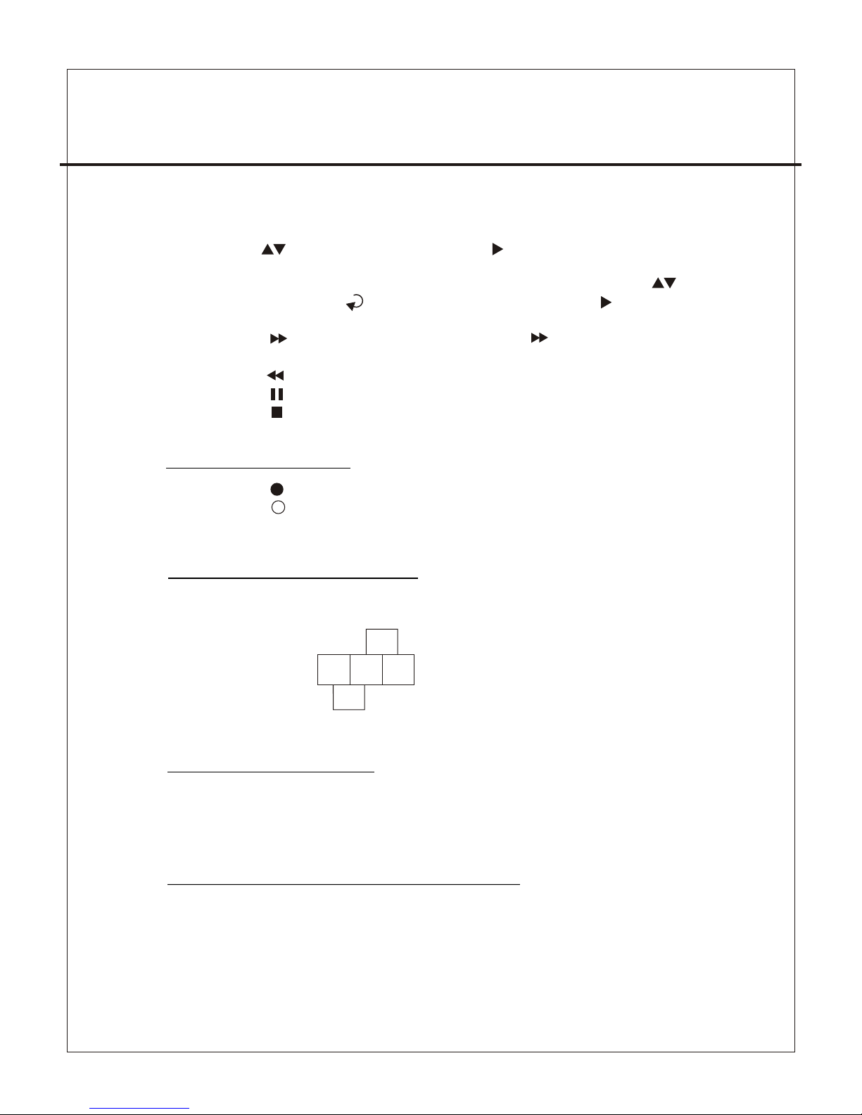
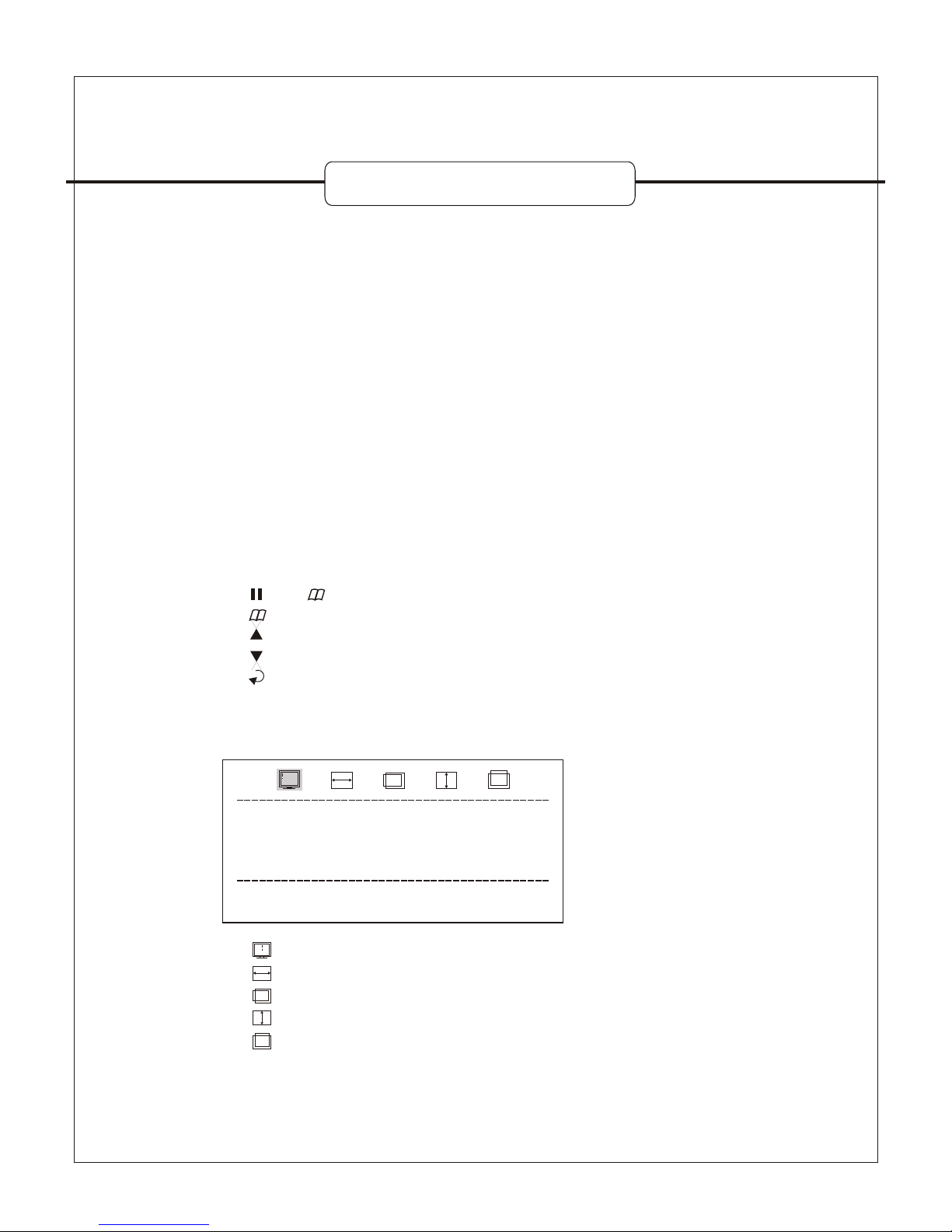
6、VIEW CONTROL
(1)Can use the following view control to monitor images from cameras.
(2)Prior to view cont rol, HDD must be formatted. Either “EACH MODE”
or “QUAD MODE” should be selected. (Refer to 5-3)
(3)In mode of “QUAD MODE”, view control is only for quad display not
available for CH1, CH2, CH3, Ch4
Camera #1 (Ch1) Camera #2 (CH2)
Camera #3 (Ch3) Camera #4 (CH4)
QUAD Display,Auto switching function.
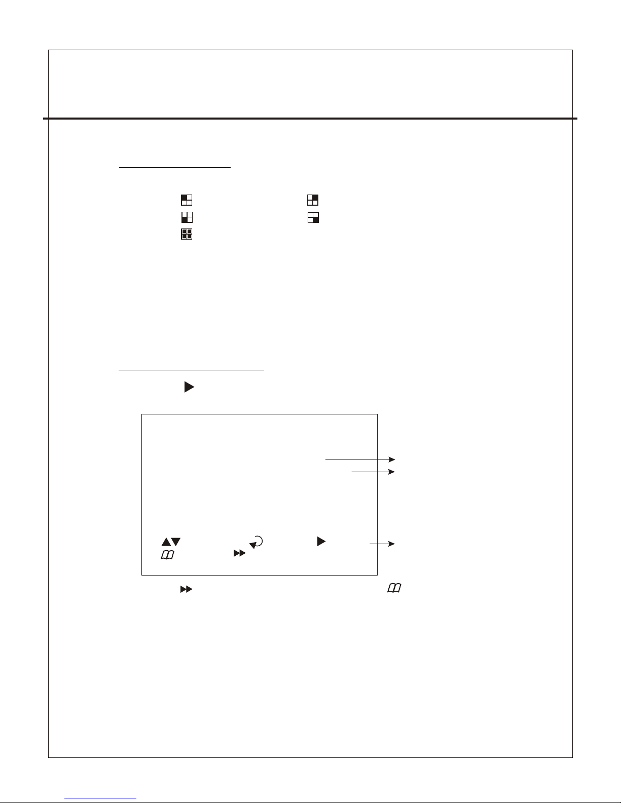
7、PLAYBACK CONTROL
(1)Press , and the system shows the recorded period.
(2)Each period is as four hour
SEARCH TIME
HARD DRIVER: MASTER
04/04/01 02:47:56 - 04/04/01 02:47:56
01 TIME 2004/12/10 02:47:50
02 TIME 2004/12/10 02:47:50
03 TIME 2004/12/10 02:47:50
( ):SELECT ( )SET ( )PLAY
( )EXIT ( )SELECT EVENT/TIME
Select HD D
Select St art Date/
Time to End Date/Time
Event rec ord
start Dat e/Time
-1 1-
Press to select EVENT or DATE / TIME , Press to exit.
Page 14
4CH STA NDALONE DV R
8、RECORD CONTROL
(1)Press to start recording.
White indicates recording.
(2) During recording, the mark ” * ” appears in status of overwriting
9、NTSC / PAL SYSTEM SETUP
(1) Replace the jumper to change system.
(2) J1 as follows:
PAL
NTSC
J1
11.4CH Recording Hours on 80GB Hard Drive
*Thereinaf ter a rough estimate a table for reference only, recording data
quantity can follow an image a variation a rate somewhat different.
(1)EVENT :
Press choose one period, then press to play.
(2)DATE / TIME :
The signal ”>” goes up to the “HARD DRIVER: MASTER”. Pres s
to select items. Use select to change data, Then press to play.
(3)PLAYBACK :
*Press to speed forward. Continue to press and show
x2、x4、x8 multiple playing.
*Press to show x2 multiple back motion.
*Press to pause.
*Press to stop.
-1 2-
Strike the button "pause" five times continually, "L" pops up on the left, to enable .
Keypad lock-up feature.
Strike the button "pause" five times again, "L" not found, to unlock keypad.
10.Keypad Lock-up Setup:
Page 15

4CH STA NDALONE DV R
Recording Results in NTSC Format
30 fps 15 fps 7 f ps 1 fps
Video
Signal
Display
Format
Video
Quality
NTSC
PAL
QUAD
MODE
EACH MODE
(Full Screen)
QUAD
MODE
EACH MODE
(Full Screen)
High
Normal
Basic
High
Normal
Basic
36Hours 72 Hours 144 Hours 1,080 Hours
48 Hours 96 Hours 192 Hours 1,440 Hours
58 Hours 116 Hours 232 Hours 1,740 Hours
64 Hours 128 Hours 256 Hours 1,920 Hours
90 Hours 180 Hours 360 Hours 2,700 Hours
112 Hours 224 Hours 448 Hours 3,360 Hours
Recording Results in PAL Format
Video
Signal
Display
Format
Video
Quality
High
Normal
Basic
High
Normal
Basic
38 Hours 76 Hours 152 Hours 950 Hours
48 Hours 96 Hours 192 Hours 1,200 Hours
60 Hours 120 Hours 240 Hours 1,500 Hours
62 Hours 124 Hours 248 Hours 1,550 Hours
90 Hours 180 Hours 360 Hours 2,250 Hours
118 Hours 236 Hours 472 Hours 2,950 Hours
25 fps 12 fps 6 f ps 1 fps
-1 3-
Page 16
-1 4-
Introduction
This document is the Operation Manual for DVR Viewer. The application will show you
stream image stored in the HDD which was previously formatted and recorded by the DVR.
If any DVR HDD is connect ed to your PC, the application will automatically
detect the HDD and show the recorded stream. You c an also save the current screen
to a BMP file, and save the current stream to a MYS stream file or an AVI file.
The application consists of two functional modules:
◆ DVR HDD PC Viewer Shows stream stored in the HDD directly.
◆ MYS File Player Plays captured stream MYS file.
Document History
◆ V1.0
Requirement
Recommendation
Installation
Hardware Installation
As stated above, the application shows stream which is stored in DVR HDD.
Before installing and executing the application, make sure that you connected DVR
HDD to the IDE cable of your PC directly, or via USB HDD adaptor
◆ OS Windows 2000 / XP or later
◆ DirectX DirectX 7.0 or later
◆ CPU 1.0 GHz or Higher
◆ RAM 256 MB or Greater
12.DVR Viewer User Guide Revision V 1.0.N.EN
Page 17
4CH STA NDALONE DV R
-1 5-
Software Installation
Execution
Make sure that the OS of your PC is Windows 2000 or later [XP or 2003]. Otherwise,
the application will not operate properly. Double click on the DVR_Setup.exe to
install the program.
Just double click the shortcut of the execution file. The application first detects
physical HDDs installed at your PC and search for DVR HDD among them.
This process may take up to 1 minute.
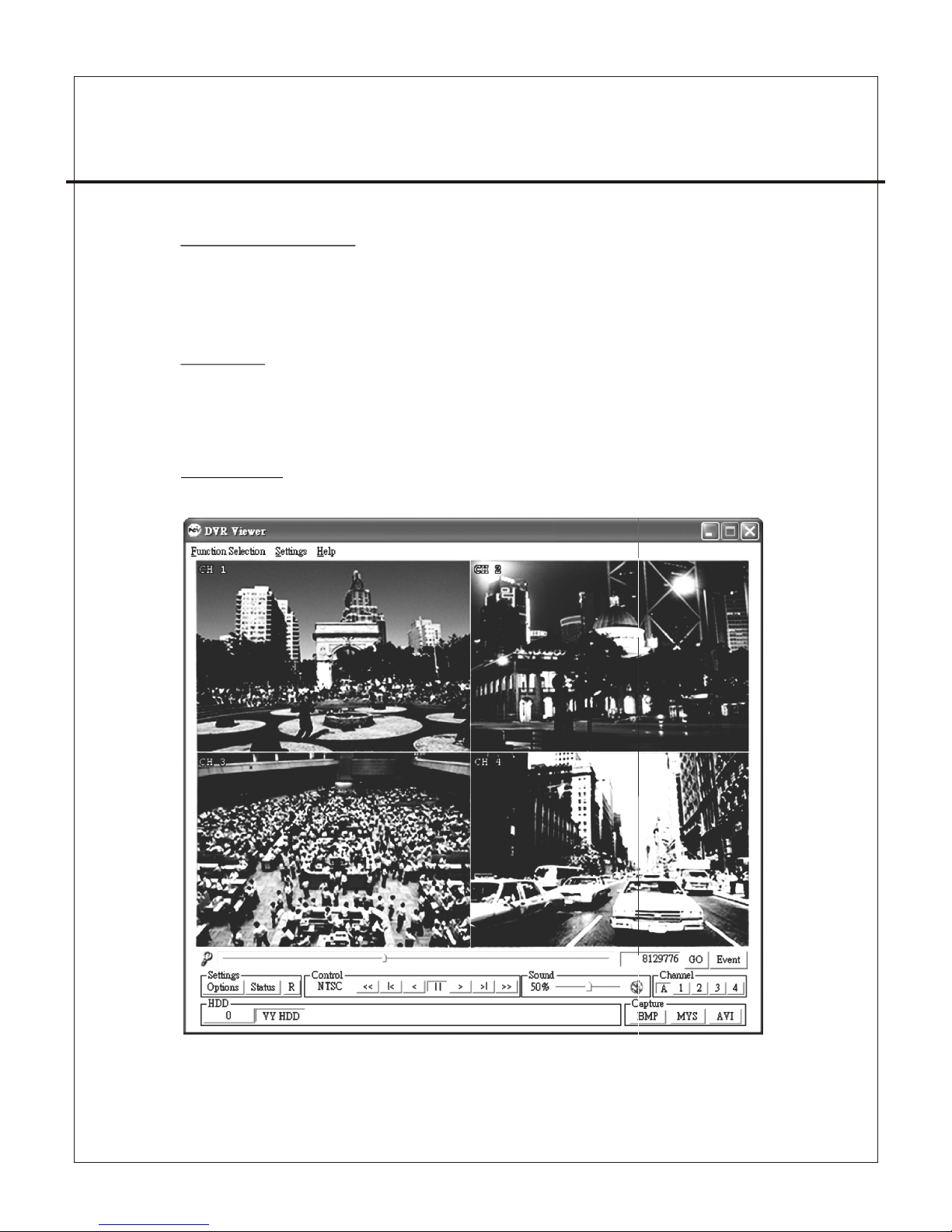
DVR Viewer
User Interface
Page 18

4CH STA NDALONE DV R
-1 6-
Functions
Valid Stream Region Indication
Once a DVR HDD is selected, the application detects valid stream region where valid
video stream resides. You can drag this to access the whole streams of the DVR HDD.
Direct Access
If the stream stored in a DVR HDD is quite long, you may have difficulty to find the
exact scene you want to s ee. When you find a scene you would like to show your
friend or report to police officers later, please remember the number in the Direct
Access Input edit box, so that you can go there directly by entering the number in
the edit box and pressing “GO” button besides it.
Events List Button
You can access the latest 64 events and go to the event directly by this button.
Page 19

4CH STA NDALONE DV R
-1 7-
Configure
Options Button
You can change application settings such as MYS file save directory,
or default video mode (NTSC/PAL). To change setting, press Options button
Status Button
Show the status on the sc reen.
Reset Button
Reset the program.
Playback
Once a DVR HDD is selected, the application automatically displays first screen
recorded at the very beginning of it. Then, you can see stream at anywhere within
the valid stream reason.
Channel Selection
The default screen display channel setting is ALL CHANNEL, which shows all four
channel (if the stream has 4 channel streams) at the same time. If you want to see
a channel only or enlarge one channel, press any channel button you want.
Page 20

4CH STA NDALONE DV R
-1 8-
HDD Selection
Once the application detects one or more DVR HDDs, it automatically selects the
first DVR HDD. You can select any DVR HDD [the DVR HDDs are marked as "VY HDD ".
However, you cannot select the normal HDD, which may be Windows-formatted one.
Capturing Button
Screen Capturing
If you want to capture, or backup, current screen, press Capture Current Screen
button. Then it will capture the current screen and saves it as BMP file.
Stream Capturing Button
If you wan to capture, or backup, current stream, press Capture Current Stream
button.Then it will record the stream you want. It will create .MYS file, whose format
is Vineyard Technologies’ proprietary stream file format. You can play the recorded
file using MYS file player.
Stream Capturing Button
If you wan to capture, or backup, current stream, press Capture Current Stream button.
Then it will record the stream you want. It will create .AVI file. You can play the recorded
file using any player which support AVI file.
MYS File Player
You can play the recorded MYS file using MYS file player.
Page 21

-1 9-
13. (Option)Video Server Board Installation
Illustration:
1.Stop the power supply.
2.Remove the cross piece from LAN port.
3.Put the video server board against the LAN port.
4.Fix the board with the screws.
5.Pull out the cable P3 from mother board and slot it in P1 on video server board.
6.Slot one end of IDC-20P cable in P2 on video server board , the other end in
P3 on mother board.
7.Slot an other cable one end in P4 on video server board , the other in P10 on
mother board.
P10
Page 22

-2 0-
DVR LAN Functional Specification
Network Interface
LAN Connector
Protocol
Link Method
Remote Control
Remote Access
10/100 Base T,Ethernet
RJ-45
HTTP,TCP/IP,UDP,ICMP,ARP,BPDU
ADSL, ISDN, LAN, Internet / Intranet
Live image、playback、set menu、record
Standard Browser : Microsoft I E Browser / Netscape Browser
with JAVA Support.
CH3
CH4
IP
INIT
LAN
G 1 G 2 G 3 G 4 C NO
IN ALAR M OUT
(4) (3) (2) (1)
(1)、TCP/IP Port as diagram below :
1.Ethernet RJ-45
2.100Mbps/link/Active indicator. (or ange)
3.10Mbps/link/Active indicator. (green)
4.IP-INIT SETUP : 192.168.0.100 the default IP for initialization
(IP INIT)
a.As shown jumper is to be
on the left
b.How we initialize the IP?
1.Put the jumper to the r ight.
2.Reboot the DVR.
3.Put the jumper to the left again.
4CH STA NDALONE DV R
Page 23

4CH STA NDALONE DV R
-2 1-
PIN#
(2)、PC to DVR Setup :
1. Use a cross-over cable to connect DVR and PC.
Definition of cross-over cable:
Brown
Brown/ Whi te
Green
Blue/W hit e
Blue
Green/ Whi te
Orange
Orange /Wh ite
8
7
6
5
4
3
2
1
Green/ Whi te
Green
Orange /Wh ite
Blue
Blue/W hit e
Orange
Brown/ Whi te
Brown
1
2
3
4
5
6
7
8
COLOR
2. Default IP and other parameters.
Above two items are changed IP
Routor or not subject to router
parameters.
3. IP AMENDED ON PC SIDE.
Domain of DVR and PC must be the same. For example of windows 2000/XP:
◆ Network Connections→Local Area Connection,Click the right button to
find Properties.
Page 24

-2 2-
◆Click Internet Prot oc ol (TCP/IP) and click Pro pe rties.
◆Input the IP address ,subnet mask & gateway as below click OK.
◆Wait until d ata u pda ted completed .
◆Execute IE b row ser .
◆Input the fo llo win g IP address to sta rt co nne ction.
Http: //1 92. 168 .0.100
Welcome to "DVR Network" comes up hereafter.
Username:admin
Password :1234
Click enter fo access r emote site.
4CH STA NDALONE DV R
Page 25

-2 3-
Remote site picture as follows.
※Download JAVA software if images not found.
Website http://www.java.com
Interne t
61.222.12.123
12.234.123.123
(3)、Setup via ADSL Modem :
1.Cross over cable in use.
2.definition of cross-over cable:
4CH STA NDALONE DV R
Page 26

-2 4-
Interne t
61.222.12.123
12.234.123.123
IP Router
192.168.0.1
Gateway
Port 80 192.168.0.100→
Port 81 192.168.0.101→
PIN#
Brown
Brown/ Whi te
Green
Blue/W hit e
Blue
Green/ Whi te
Orange
Orange /Wh ite
8
7
6
5
4
3
2
1
Green/ Whi te
Green
Orange /Wh ite
Blue
Blue/W hit e
Orange
Brown/ Whi te
Brown
1
2
3
4
5
6
7
8
COLOR
3.Prior to installation,IP address setup must be well done.
(4)、Connection Via Router or Hub.
◆Setup procedure same as previous description.
◆In use of Router , distributor and Hub.
◆We connect DVR & devices above with the cable as fol lows:
Brown
Brown/ Whi te
Green
Blue/W hit e
Blue
Green/ Whi te
Orange
Orange /Wh ite
8
7
6
5
4
3
2
1
1
2
3
4
5
6
7
8
4CH STA NDALONE DV R
Orange /Wh ite
Orange
Green/ Whi te
Blue
Blue/W hit e
Green
Brown/ Whi te
Brown
Page 27

14. SXGA CARD FOR DVR (Option)
1.SXGA 1280*1024 High Resolution.
2.Supports LCD/CRT/Projector/Plasma TV.
3.Plug & Play free from driver & software.
4.NTSC/PAL jump swappable.
5.On Screen Display(OSD).
∣、 Feature:
Signal input : digital signal input to DVR.
Signal output : VGA monitor output.
Power input : DC +5V from D VR.
Power consumption : 800mA.
Ⅱ、Specification:
LCD/CRT monitor with VGA input.
Projector with VGA input.
Ⅲ 、 System Requirement:
1. + : entrance of VGA menu setup.
2. : exit.
3. : left/decrease.
4. : right/increase.
5. : swap/enter.
Ⅳ 、 Guideline on keypad:
OUTPUT TIMING
Press ENTER to setup
15 : 1280 x 1024@60Hz ?
1280 x 1024@60Hz
Ⅴ 、 Instruction:
The initial display o n VGA monitor
-2 5-
1. OUTPUT TIMING: Resolution and Frequency Adjustment.
2. H ZOOM: Horizontal Zoom.
3. H PHASE: Horizontal Phase.
4. V ZOOM: Vertical Zoom.
5. V PHASE: Vertical Phase.
Page 28

#Press Menu and Pause to enter VGA.
#Press to move left and right setup menu.
#Press enter to swap decrease and increase feature.Press to decrease and increase.
#Press enter again to left and right feature or to confirm setup.
#Press Menu to exit VGA setup menu ,for DVR operation.
Ⅵ 、 Installation:
-2 6-
4CH STA NDALONE DV R
Procedure:
1.Uncover DVR.
2.Remove the block behin d DVR.
3.Remove the connector l inking to control board .
4.Unfasten two screws as d iagram.
5.Mount two copper bolts o n the cabinet bottom.
6.Connect motherboar d and VGA board with two cable s of 2 0pin IDC.
7.Insert VGA Card.
8.Fasten VGA connector screws.
9.Fasten VGA Card screws.
10.Plug in connector to VG A Card.
11.Connect to VGA mo nitor.
12.Test if VGA mo nitor works.
13.Put the DVR cover on the ca binet if ok.
14.Enter menu to get prope r setup.
15.Done
P5
Page 29

-2 7-
一、特性 說 明 ………… … … ………… … … ……… 28
二、規格 … … ………… … … ………… … … ……… 29
三、安裝 說 明 ………… … … ………… … … ……… 30
四、按鍵 說 明 ………… … … ………… … … ……… 31
五、操作 說 明 ………… … … ………… … … ……… 32
六、監看 控 制 ………… … … ………… … … ……… 36
七、放影控制……… … … ………… … … ………… 36
八、錄影控制……… … … ………… … … ………… 37
九、NTS C / PAL 設定 … … ………… … … ………… 37
十、按鍵 鎖 設 定……… … … ………… … … ……… 38
十一、硬 碟 錄 影時間概 算 表 ………… … … ……… 38
十二、DVR Viewer 軟 體 使用說 明 … … ……… … 39
十三、網 路 卡 簡易安裝 說 明(選 配)………… … … 44
十四、SXGA 卡 FOR DVR 說明(選配)……… … 50
4 路單機 數位錄 影系統
目 錄
Page 30

-2 8-
1、真正Sta n d - alone 獨立 機 種 。
2、30張圖像 即 時 顯 示、更新速度 。
3、具同時錄 影 與 即 時顯示功能。
4、錄影模式 可 選 擇4畫 面(合頁)及單一畫面(分 頁)方 式 。
5、可選擇NT S C / PAL 系統。
6、壓縮格式 採 用 修 正式MJPEG。
7、提供手動 、 異 動 、排程、事件 觸 發 等 錄影方式。
8、四組輸入 , 一 組 輸出之警報接 點 , 警 報時自動錄影(時間 可 調)。
9、可依日期 、 時 間 快速搜尋播放 功 能 。
10、停、復 電 自 動 回復錄影模式 。
11、硬碟使 用 狀 態 可由面板LED顯 示 。
12、可使用U S B連 接P C,播放器可依 時 間 搜 尋播放、存檔、 快 照 等 功能。
13、內建異 動 檢 知 功能。
14、自動跳 台 功 能 。
15、具有Lo o p i ng輸出。
16.具有按 鍵 鎖 功 能。
一、特性說明 :
4 路單機 數位錄 影系統
Page 31

二、 規 格 :
說 明
NTSC/PAL
Embedded RTOS
4組
2組(VCR OUT/ MONITOR OUT)
NTSC
PAL
NTSC
PAL
NTSC
PAL
224
PAL
Modifend 低
MJPEG 中
高
連續錄影/異動 錄影/錄影排程設定/警報錄影
顯 示 NTSC 720x480
PAL 720x576
錄 影 NTSC 640x
640x272
項 目
視頻訊 號 格式
作業系 統
視頻輸 入 數
視頻輸 出 數
顯示張 數
錄影張 數(合 頁)
錄影張 數(分 頁)
錄影模 式
解析度
壓縮方 式
硬碟
備份
搜尋
警報輸 入
異動檢 知
斷訊檢 知
自動跳 台
蜂鳴器 警 報輸出
亮度調 整
對比調 整
USB輸出
Looping輸 出
按鍵鎖 功 能
系統監 視
電源規 格
尺寸
重量
網路卡
模式
全螢幕
VCR
4 / 1
停、復電自動回復錄影模式
最大400GB x 2 (內建 硬碟80GB)
時間/日期/事件
是
輸入 輸出
是
是
是
是
是
是
是
是
是
120 fields/s (4x30 fields/s)
100 fields/s (4x25 fields/s)
最大 30 fps
最大 25 fps
最大7.5 fps (30 fiel ds/s÷4ch)
最大6.25 fps (25 fie lds/s÷4ch )
12K Bytes / F rame
15K Bytes / F rame
20K Bytes / F rame
-2 9-
4 路單機 數位錄 影系統
DC 12V / 4A(AC100V~240V 50/60HZ)
430mm x 300mm x 48mm (W x D x H)
3.5KG
10/100M
Page 32

-3 0-
三、安裝說明 :
後板介紹 及 操 作說明:
(1) 第1~ 4支 攝 影機之影像 訊 號 的輸入及L o o ping輸出 。
(2) 本機 的 影 像輸出端, 請 將 監視器的 影 像 輸入端(Vi d e o In)
連接至此 輸 出 端。
(3) 錄影 的 影 像輸出端, 請 將 錄放影機 的 影 像輸入端(V i d eo In)
連接至此 輸 出 端。
(4) 警報S e n sor的輸入 及 輸 出的連接 座 , 連接點如下 :
1、第1支攝影 機 的 警報共點(C O M )。
2、第1支攝影 機 的 警報輸入。
3、第2支攝影 機 的 警報共點(C O M )。
4、第2支攝影 機 的 警報輸入。
5、第3支攝影 機 的 警報共點(C O M )。
6、第3支攝影 機 的 警報輸入。
7、第4支攝影 機 的 警報共點(C O M )。
8、第4支攝影 機 的 警報輸入。
9、警報CO M輸 出 接點。
10、警報N . O 輸 出接點。
(5) 電源 輸 入 端,請使用 本 機 所附的電 源 轉 接器供電, 電 源 轉接器的
電源要求 為 A d aptor : D C-12 V / 4 A。
(6)V G A輸 出:接到VG A顯 示 器。
(7)T C P /IP:網路 線R j 45接座。
MONITOR
VCR
VIDEO
LOOP OUT
LAN
IP
INIT
IN ALARM OUT
DC 12V
VGA
(1)(2)(3) (4) (5)(7)
(6)
4 路單機 數位錄 影系統
Page 33
-3 1-
四、按鍵說明
前面板介 紹 及 操作說明:
(1) 錄影 指 示燈
(2) 硬碟1讀 寫 指示燈 (M A STER )
(3) 硬碟2讀 寫 指示燈 (S L AVE)
(4) CH 1全 畫面顯示 ( C H1)
(5) CH 2全 畫面顯示 ( C H2)
(6) CH 3全 畫面顯示 ( C H3)
(7) CH 4全 畫面顯示 ( C H4)
(8) 4分割 監 看模式 (Q U AD)、跳 台 功能
(9) 主選 單 ,硬碟使 用 量顯示(錄影)鍵
(10) 選 項+ 1(UP )
(11) 選 項- 1 (DOW N )
(12) 選 擇/設 定鍵 (SE L ECT)
(13) 錄 影 鍵 (REC O RD)
(14) 暫 停 (放 影)鍵 (PAU S E),按鍵 鎖 鍵
(15) 反 快 轉 (放影)鍵 (RF )
(16) 停 止 鍵 (STO P )
(17) 放 影 鍵 (PLA Y )
(18) 正 快 轉(放影) 鍵(FF )
(19) U S B端子
(20) 硬 碟 抽取盒(T Y PE B)
(1) ( 2) (3)
(4) ( 5) (6 ) (7) (8)
(9) ( 10) (11) (1 2) (13)
(14 ) (15) (1 6) (17) ( 18)
(19 )
4 路單機 數位錄 影系統
USB
TYPE B
USB
TYPE A
(20 )
Page 34

-3 2-
五、操作說明 (主 選 單)
主選單
系統設 定
攝影設 定
錄影設 定
錄影排 程
硬碟設 定
系統恢 復
( ):選擇 ( ) :設 定 ( ):離開
按 鍵,選擇 欲 設 定之項目, 按 鍵 , 進入設定 ,
按 鍵,離開 主 選 單。
5-1:系 統 設 定
系統設 定
蜂鳴器 :2 S
感應器 :5 S
斷訊 :ON
位移 :ON - OFF
感應 :ON
密碼設 定
時間設 定
( ):選擇 ( ) :設 定 ( ):離開
(1)蜂鳴 器 警 報時間長短 設 定 ,1-30秒 。
(2)感應 器 警 報時間長短 設 定 ,0-30秒 、C O NT(連續輸 出)。
(3)斷訊 、 位 移、感應警 報 :O N開/OFF關 。
(4)位移 警 報 :ON-OF F (有 四種選擇), 前 為 警報開關、 後 為 跳警報畫面 。
5-1- 1 :密 碼設定
設定變更 使 用 之密碼,畫 面 如 下 :
舊密碼 : _ ___ _ _
新密碼 : _ ___ _ _
新密碼 確 認 :__ _ ___
4 路單機 數位錄 影系統
Page 35

-33-
(1)當密 碼 輸 入無誤時, 畫 面 則顯示 : “ 新密 碼 確 認 ”。
(2)若密 碼 不 正確時,畫 面 則 顯示 : “ 密碼錯 誤 ” 。
* 使用監看 鍵 來 輸入密碼, 圖 示 如下:
代表:"1" 代表:"2" 代表:"3" 代表:"4" 代表:"5"
5-1- 2 :時 間設定:
設定變更 時 間 日期,畫面如下:
時間設 定
200 4 /12 / 17 18: 0 0:3 0
顯示:上1
( ):選擇 ( ) :設 定 ( ):離開
按 鍵,選擇欲調 整 之 時間項目,按 鍵,使數 值+ 1 ,
按 鍵,離開,並且記 憶 設 定值。
時間顯示 設 定:上1 -為顯示於右 上 方 ,日期時 間 以 一行顯示
上2-為顯示 於 右 上方,日期 時 間 以二行顯 示
下1-為顯示 於 右 下方,日期 時 間 以一行顯 示
下2-為顯示 於 右 下方,日期 時 間 以二行顯 示
5-2:攝 影 設 定:
攝影設定
攝 影 :Ch1
錄影設定 :ON
亮度設定 :5
對比設定 :5
感應設定 :N-O
位移設定 :ON
感度設定 :5
跳台時間 :5 S
( ):選擇 ( ):設定 ( ):離開
按 鍵,選擇 欲 設 定之項目, 按 鍵 , 使數值+1,
按 鍵,離開 , 並 且記憶設定 值 。
4 路單機 數位錄 影系統
Page 36

-3 4-
(1)每支 攝 影 機各別設定(預 設 值 為CH1)。
(2)錄影 設 定 : 設 定此攝影機 是 否 要錄影。
(3)亮度/對 比 設 定 : 5為標準值。
(4)感應 設 定 : 警 報開關動作N - O (常開)、N-C (常 閉) 、- ---(無動 作) 。
(5)位移 設 定 : 異 動位移,ON開/ O F F關。
(6)感度 設 定 : 異 動位移之感 度 。
(7)跳台 時 間 : 跳 台時間設定 。
5-3:錄 影 設 定
錄影設 定
錄影設 定 :分頁
錄影品 質 :中
錄影張 數 :30張
警報錄 影 張數 :1 5張
警報錄 影 時間 :5 S
( ):選擇 ( ) :設 定 ( ):離開
5-4:錄 影 排 程
(1) 錄影 設 定:分 頁(圖框方式錄 影) 、 合 頁(四分割畫 面 錄 影)。
(2)錄影 品 質:選 擇錄影畫質 解 析 度,高、 中 、 低三種解析 度 選 項。
(3)錄影 張 數:
合頁(四分割 畫 面 錄影)錄影張數 。
→ 30、20、15、1 0、7 . 5、6、5、4、3、2、1 fps
→ 在此模式 時 , 按鍵 、 、 、 失效。
分頁(圖框模 式), 有 下列的選擇 方 式 :
最多 7.5 f p s . (每台攝影機) 總 數 : 3 0 fps = 7. 5 x 4 C H
(4)警報 錄 影 張數: 於錄影中 , 有 警報即錄 影 此 項設定之張 數 。
(5)警報 錄 影 時間 : 於錄影中 , 有 警報即錄 影 此 項設定之時 間 ,
最長可達6 0秒 。
※(4) (5 )項 功 能僅在“ 錄影 排 程 “ 中有設定 為 ”S“ 的時段才有 效 。
TTTTTTTTTTTTTTTT TTTTTTTT
: : : : : : : :
0 3 6 9 12 15 18 21
( ):選擇 ( ) :設 定 ( ) :離開
錄影排 程
4 路單機 數位錄 影系統
Page 37

-3 5-
按 鍵,選擇 欲 設 定之項目, 按 鍵 , 使數值改 變 ,
按 鍵,離開 , 並 且記憶設定 值 。
(1)可使 用 鍵 ,來改變錄 影 模 式。
(2)時間 以0 - 24小時為範 圍 。
(3)設定 “T” 該 時 段 為可(自動) 持續錄 影 。
(4)設定 “S” 該 時 段 為警報錄影 。
(5)設定 “ - ” 為 該 時 段不錄影。
5-5、硬碟 設 定
硬碟設 定
硬碟覆 寫 : (YE S )
主硬碟 容 量: 80 0 00MB
主硬碟 用 量: 0M B 0 %
清除主 硬 碟:
副硬碟 容 量: N/ A
副硬碟 用 量: N/ A
清除副 硬 碟
( ):選擇 ( ) :設 定 ( ):離開
按 鍵,選擇需 設 定 之 項目,按 鍵,改 變 設 定值,
按 鍵, 離開,並 且 記 憶 設定值。
(1)硬碟 覆 寫:
當錄影時 硬 碟 錄滿後,當 設 定 :
YES : 以4小時 為 單 位,進行硬 碟 覆 寫動作 (持續 錄 影)。
NO : 停止錄 影
(2)主硬 碟 狀 態
顯示主硬 碟 之 使用情況, 包 含 硬碟之容 量 及 使用量百分 比 。
(3)清除 主 硬 碟(硬碟格式化)
當選擇此 項 設 定時,畫面 會 出 現要求輸 入 六 位數密碼。
當輸入的 密 碼 正確時,則 出 現 : “ 密 碼確認“
密碼錯誤 時 否 則出現 : “ 錯 誤“
*密碼出廠 設 定 值為(111 1 1 1)
*當硬碟需 要 做 安裝、更換 時 , 需要重新 做 硬 碟格式化的 動 作 。
4 路單機 數位錄 影系統
Page 38

-3 6-
5-6、系統 恢 復
系統恢復原 廠 設 定 值。
六、監看控制
(1)可使 用 下 列各鍵,來 監 看 各輸入攝 影 機 之影像。
(2)使用 本 監 看控制功能 時 , 需先至5- 3 錄 影 模式中設定 為 ” 分 頁“。
(3)設定 為 “ 合頁“時, 此 監 看控制功 能 僅 提供4分割畫面 顯 示 ,
所以CH1、C H 2、C H3、CH4按鍵 均 失 效。
CH1全畫面 顯 示 ( C H1)
CH2全畫面 顯 示 ( C H2)
CH3全畫面 顯 示 ( C H3)
CH4全畫面 顯 示 ( C H4)
4分割監看模 式 ( Q U AD)、跳台功 能 。
七、放影控制 :
放影鍵 按下時 , 將 顯 示游標停留在 目 前 當 下使用中的硬碟 之 事 件 列表上,
並於上方顯 示 游 標 所在地之可播 放 的 起 始時間至結束時 間 , 供 使用者參考。
搜尋時 間
硬碟 : 主硬 碟
04/ 0 4/0 1 0 2:47 :56 - 04 / 04/ 0 1 02: 4 7:5 6
01 TI M E 200 4 /12/ 10 02: 4 7:5 0
02 TI M E 200 4 /12/ 10 02: 4 7:5 0
03 TI M E 200 4 /12/ 10 02: 4 7:5 0
( ):選擇 ( )設 定 ( )放影
( )離開( )選 擇 時段/時間
選擇硬 碟
欲撥放 之起始 與
結束日 期、時 間.
1.當按下 鍵 時 , 游標會跳到 選 擇 硬碟項目 , 此 時按 鍵,選擇 欲 播 放之硬碟
,下方之 事 件 列表也隨之 更 新 。
(1)事件 列 表 時段放影:
於事件列 表 下 ,按 鍵,選擇 欲 播 放之事件 時 段 後,直接再 按 一 次放影鍵
,則進行 放 影 動作。
4 路單機 數位錄 影系統
時段記 錄起始
日期、 時間.
Page 39

-3 7-
八、錄影控制
(1)當錄 影 鍵 按 下時,本機 開 始 錄影,在 畫 面 上中間位置 出 現 白色
圓形 之圖示 表 示 為錄影中, 以 便 確認。
(2)錄影 時 , 當硬碟錄滿 後 , 如有硬碟 覆 寫 設定時,在 畫 面 右下角會有
” * ”號出現 。
九、NTSC / PAL 系統設定 :
(1)調整 機 板 上J1的2P短路插 梢 位 置後,再 重 新 開機便可。
(2)J 1 位 置 如下 :
PAL
NTSC
J1
4 路單機 數位錄 影系統
2.事件列 表 中 每一筆事件:
(1)T I M E:自動於四 小 時 的倍數時 間 , 新增一筆整 點 事 件記錄時段 , 並 繼續錄影 。
(2)S E N SOR:當感 應 器 警報或位 移 警 報時,新增 一 筆 警報事件記 錄 。
3.放影中:
◆ 當正快轉 按下時 , 畫 面會正快轉 ,連續 按 下時會成x 2、x 4、x 8倍數快轉。
◆ 當反快轉鍵 按 下 時 ,畫面會成x 2倍 數 反快轉。
◆ 當暫停鍵 按 下 時 ,畫面暫停 。
◆ 當停止鍵 按 下 時 ,停止放影 。
(2)指定 硬 碟 日期/時間放影:
於游標跳 到 選 擇硬碟項目 時 , 按 鍵及按 鍵, 去 調 整改變日期/
時間數值+ 1, 設 定完成時再 按 一 次放影鍵 , 則 進 行放影動作 。
於任一其 間 按 鍵 者,則離開 。
Page 40

-3 8-
NTSC錄影方式 設 定
影像訊號 放影畫面 影 像 品 質
高階
中階
低階
高階
中階
低階
四分割
(QUAD MODE)
單一畫面
(EACH MODE)
NTSC
PAL錄影方式設 定
影像訊號 放影畫面 影 像 品 質
高階
中階
低階
高階
中階
低階
PAL
30fps 15fps 7fps 1fps
36時 72時 144時 1,080時
48時 96時 192時 1,440時
58時 116時 232時 1,740時
64時 128時 256時 1,920時
90時 180時 360時 2,700時
112時 224時 448時 3,360時
25fps 12fps 6fps 1fps
38時 76時 152時 950時
48時 96時 192時 1,200時
60時 120時 240時 1,500時
62時 124時 248時 1,550時
90時 180時 360時 2,250時
118時 236時 472時 2,950時
四分割
(QUAD MODE)
單一畫面
(EACH MODE)
十一、4CH連續錄影硬碟容量概 算 (以8 0 G硬 碟 為 例)
* 以下概算 表 僅 供參考,記錄資 料 量 會依影像 變 動 率有所不同 。
4 路單機 數位錄 影系統
十、按鍵鎖設定:
暫停 ( 放影 ) 鍵 (PAUSE) ,按 5 次,顯示器在左下角會出現 "L" 字樣,即為按鍵鎖功能開啟,
當要解除按鍵鎖功能時,再按 5 次,此時顯示器左下角 "L" 字樣會消失,即為按鍵鎖功能關閉 .
Page 41

-3 9-
◆ DV R Viewer可播放錄 製於 DVR(數位錄影機)硬 碟中 之影像。
◆ 如有 任何 DVR 格式的硬碟連 接至您的電腦,軟體 將會 偵測到此顆硬碟,並 依照您
的指 示播放影像。
◆ 可將 D VR 硬碟中的影像存成 B MP 圖檔。
◆ 可備 份 DVR 硬碟中動態影像 資料(MYS格式)至其它的 儲存 媒體(如HDD;CD-R W;USB碟)。
◆ 可將D VR硬碟中的影像轉存 為 AVI 檔案格式。
十二、DVR Viewer 軟體使用說明 (版本 V1.0.N.CH)
◆ DVR數位錄 影 機 播 放器 直接從DVR格 式 的 硬 碟中播放或轉錄 影 像
◆ MYS檔案播 放 器 播 放M YS格式的檔案
DVR Viewer 主要包括兩個 應 用 模 組 :
文件版本更新記錄
◆V1.0
文 件 中 之專 有 名 詞
◆ DVR 數位影 像 錄 影 系統
◆ MYS 數位錄 影 機 硬 碟中儲存檔案 的 格 式 。為一低失真之 格 式 。
◆ AVI 影像檔 格 式 , 可在大多數作 業 系 統 上播放。
安 裝 需 求
作業系統 Wi n d o ws 2000 / XP 或 更 新 版 本
Direc t X D i rectX 7. 0 或 更 新 版本
建 議 需 求
CPU 1.0 GHz 以上
記憶體 256 M B 以 上
4 路單機 數位錄 影系統
Page 42

-4 0-
安裝
硬體安裝
◆ 本軟體主要的功能是播放並備份 DVR 中所錄製的影像。
◆ 在您安裝與執行本軟體之前,請先確定您的電腦已經連接上 DVR 中的硬碟。
◆ 您可以直接將 DVR 中的硬碟經由 IDE 介面連接上您的電腦,或經由 USB 介面
直接將電腦與 DVR 相連。
軟體安裝
◆ 請確定您的作業系統為 Windows 2000/XP 或更新的版本。否則本程式將無法順利執行。
◆ 請執行光碟內之 DVR_Setup.exe 並依螢幕提示進行安裝。
執行
◆ 請點選 開始→ 程式集→ DVR Viewer → DVR Viewer 啟動程式,也可以直接雙擊
桌面上的 DVR Viewer 捷徑啟動程式。
◆ 程式執行時,首先會偵測您電腦上所有安裝的實體磁碟機,然後會在其中偵測是否
為 DVR 格式之硬碟。這個偵測的過程須時約一分鐘,然後進入程式主畫面。
DV R數 位 錄影 機 播放 器
使用者介 面
4 路單機 數位錄 影系統
Page 43

-4 1-
功能
硬碟內容導 覽 軸
此軸直 接 對應整 個 硬碟影像 記錄的內 容。
您可以 直 接瀏覽 硬 碟內的所 有影像。
注意: 此 軸直接 對 應硬碟內 部記錄, 所以也可 以 看到硬 碟 覆寫(格式化)前 的資料。
建議先 以 「事件 清 單」方式 搜尋影像 ,再使用 此 捲軸, 以 免產生時 間前後混 淆。
圖框計數器 / 圖框直接選 擇 器
當硬 碟中儲存的影像長度 非常長的時候,您將 很難 很快地尋找到硬碟中 某個您曾經
看過 的畫面。當您想要在 以後向朋友或警察們 提供 某個您想要展示的畫 面時,請記
住播 放該畫面時圖框計數 器內的計數數值。以 後您 就可以在圖框計數器 中直接輸入
該圖 框的數值,並且按下 旁邊的 「GO」 按鍵,您就可 以迅 速地找到您想要尋找 的畫面。
事件清單列表鍵
您可以快速 地 選 擇 最後64個錄影記 錄 事 件 。
事件清單 中 有 該事件開始 錄 影 與結束錄 影 的 時間。當您 按 下 「OK」按鍵時 ,
畫面即立 刻 定 位到您所選 擇 的 時間位置 。
4 路單機 數位錄 影系統
Page 44

-4 2-
程式設定鍵
Options鍵
您可以改 變 程 式內部的設 定 值 。例如, 影 片 擷取 / 備份 .MY S 檔 案 的儲存位置 。
您也可以 在 此 改變預設影 像 顯 示的格式 ( N T SC / PAL), 及 其 它程式設定 。
Status 鍵
您可以在 螢 幕 上顯示目前 播 放 的狀態。
Reset 鍵
您可以回 復 到 進入程式後 的 初 始狀態。
播放鍵
您可以控 制 影 片的正反向 播 放 、正反向 單 一 畫面快轉、 正 反 向高速快轉 與 暫 停。
頻道選擇鍵
您可以選 擇 監 看全部的頻 道 , 或放大監 看 某 個單一頻道 。
4 路單機 數位錄 影系統
Page 45

-4 3-
硬碟選擇鍵
當程式偵 測 到 一個或一個 以 上D VR格式的 硬 碟 時,程式會 預 設 選擇第一個D V R硬 碟。
您可以選 擇 任 何一個 DVR 格 式 的 硬碟(圖示上 有 V Y H DD 字樣) 來播放 。
但您不可 以 選 擇非 DVR 格式 的 硬 碟來播放 , 例 如,Wind o w s 格式的硬碟 。
影像影片擷取鍵
共有 BMP、M Y S 及 A VI 三種儲存 格 式 與按鍵可 供 擷 取選擇。
BMP鍵
當您想要 擷 取 某個靜態畫 面 時 ,您可以 按 下 鍵 並 指定儲存路 徑 與 檔名。
該畫面即 被 儲 存成一個靜 態 的 B MP 圖檔。
MYS 鍵
當您想要 擷 取 / 備 份 DVR 中的動 態 影 片時,您 可 以 按下 鍵。程式 就 會
將影片從 目 前 播放的位置 開 始 備份。您 所 備 份的影片以 . M Y S 的格式儲存 。
MYS是 DV R 內 部 標準的儲存 格 式 ,所以備 份 時 無須轉換, 備 份 速度最快且 低 失 真。
AVI鍵
當您想要 擷 取 / 備 份 DVR 中的影 片 時 ,您可以 按 下 鍵 。程式就會 將 影 片
從目前播 放 的 位置開始備 份 。 您所備份 的 影 片以 .AVI 的 格 式 儲存。
您可以選 擇 壓 縮格式與壓 縮 比 例。AVI檔 的 畫 質與轉檔所 需 的 時間,依您 的 選 擇
而有所不 同 。
注意:某 些 壓 縮格式需要 另 外 安裝加/解碼 器 , 壓縮前請先 確 定 是否有安裝 該 加/解 碼器。
MYS檔案播放器
MYS檔案播 放 器 可 播 放 備 份 下 來 的 MYS 影 片 檔 案 。
操作方式 與 介 面和DVR數位 錄 影 機播放器 相 當 類似。
4 路單機 數位錄 影系統
Page 46

-4 4-
十三、網路卡簡易安裝說明(選配)
1 、將主機電源斷電。
2 、將上蓋螺絲卸下,打開機殼上蓋後將 LAN 的檔板取下。
3 、裝上網路卡並將螺絲固定後,再將主板上的 P3 排線插頭拔起,改插至網路上的
P1 插座上。
4 、將網路卡所附的扁排線 (IDC-20P) ,一端插在網路卡的 P2 插座,一端插在主機板
的 P3 插座上。
5 、將網路卡所附的另一條排線,一端插在網路卡的 P4 插座,另一端插在主機板上的
P10 插座上。注意插頭的大小、方向是不一樣的。
網路卡安 裝 示 意圖
P10
Page 47

-4 5-
4 路單機 數位錄 影系統
DVR 網路卡 系統規 格
網路介面
網路接頭
通信協定
連線方式
遠端監控功 能
遠端監控軟 體
10/100 Base T,Ethernet
RJ-45
HTTP,TCP/IP,UDP,ICMP,ARP,BPDU
ADSL, ISDN, LAN, Internet / Intranet
Live image、playback、set menu、record
Standard Browser : Microsoft IE Browser /
Netscape Browser with JAVA Support.
(一)、網路DV R 後 面 板配置說明 如 下 圖
CH3
CH4
IP
INIT
LAN
G 1 G 2 G 3 G 4 C NO
IN ALARM OUT
(4) (3) (2) (1)
(1) 網 路RJ-45插 座.
(2)1 0 0 Mbps/ l i nk/A c t ive 指示燈. (橙 色)
(3)1 0 M bps/l i n k/Ac t i ve 指示燈. (綠色)
(4)I P - INIT 設定
即IP-I n i tial, I p位 址 恢復出廠 設 定 值之意,當 使 用 者因不明
原因修改 或 忘 記自設之網 路I P值 時可使用 此 功 能恢復出廠 設 定 值
(192 . 1 68.0. 1 0 0) 。 操作如 下 :
b.欲恢復 出 廠 設定值時, 如 下 圖所示,
先將短度 插 銷 短路右側2點.
網路DVR做 電 源 重開機.
將短路插 銷 恢 復置於左側 位 置 。
A.如下圖 , 當 一般使用情 況 時
短路插銷 的 位 置應置於左 側2點.
Page 48

-4 6-
4 路單機 數位錄 影系統
(二)、簡易1對1連線
1.使用Ca t 5 交 叉型網路線 ( C r oss- o v er cabl e ) (非 一般1對1網路線)
直接連至P . C。 交叉型網路 線 ( C ross - o ver cab l e ) 接法及定義 如 下 :
棕 8
棕/白 7
綠 6
藍/白 5
藍 4
綠/白 3
橙 2
橙/白 1
1 綠/白
2 綠
3 橙/白
4 藍
5 藍/白
6 橙
7 棕/白
8 棕
顏色
PIN #
2.網路DV R出 廠 時網路參數 設 定 值如下
此2項目提 供連接 埠數值 供修正I P 路由器 部分參 數用.
3.PC 端 以 手 動設定修改I P內 容
電腦須設 定 在 相同的網域 內 , 以微軟wi n d ows-2 0 0 0/XP 為例 , 畫 面如下:
◆ 先打開 網路 連 線 , 按滑鼠右鍵 選 擇 內 容
Page 49

-4 7-
4 路單機 數位錄 影系統
◆ 點選 Int e r net Pro t o col (T C P /IP) 選項 內 容 進 入
◆ 看到以下 畫 面 後,點選此 處 並 填入以下 數 值 按 確定 後便完成.
◆此時稍 待 電 腦更新相關 資 訊.
◆啟動IE瀏 覽 器 ,並輸入下 面 的
Ip位址 htt p://192 .168.0.100 開始連 線.
連線後的 畫 面 如下
◆輸入帳號:admin
◆密 碼:1234
enter 便可進入
Page 50

-4 8-
4 路單機 數位錄 影系統
連線後的 畫 面 如下
※ 如 無 法看到影像 畫 面 時,可至JA V A網 站中下載 免 費 驅動軟體安 裝.
網址 http://www.java.com/
(三) 直接連接 高 速M odem / AD S L M odem
In terne t
61 .222. 12.12 3
12 .234. 123.1 23
Page 51

-4 9-
4 路單機 數位錄 影系統
1.使用Ca t 5 交 叉型網路線 ( C r oss- o v er cabl e )。
2.交 叉 型網路線 (C r o ss-ov e r cable ) 接 法 及定義如下 :
3.安裝前 請 確 認已將網路D V R內 之各IP位址 設 好 後再進行連 結.
棕 8
棕/白 7
綠 6
藍/白 5
藍 4
綠/白 3
橙 2
橙/白 1
1 綠/白
2 綠
3 橙/白
4 藍
5 藍/白
6 橙
7 棕/白
8 棕
顏色
PIN #
(四) 從網際網 路( I ntern e t )經IP路由器( o r寬 頻分享器)或區 域 網 路(LAN)使 用
微軟IE瀏覽 器 直 接連線網路D V R :
In terne t
61 .222. 12.12 3
12 .234. 123.1 23
IP Rout er
19 2.168 .0.1
Ga teway
Por t 80 192. 168.0 .100→
Por t 81 192. 168.0 .101→
◆有關於 電 腦 的 連線方式 同前 說 明 一樣.
◆網路DV R若 連 線於IP路由器 、 寬 頻分享器 或 中 繼器(HUB )時 , 連接線須使
用1對1的網路線 , 如 下圖:
棕 8
棕/白 7
綠 6
藍/白 5
藍 4
綠/白 3
橙 2
橙/白 1
1 橙/白
2 橙
3 綠/白
4 藍
5 藍/白
6 綠
7 棕/白
8 棕
Page 52
-5 0-
十四、SXGA卡FOR DVR (選配)
一、特點:
二、規格:
三、系統需求:
四、按鍵說明:
五、操作說明:
1.超 高 解析度可達 SXGA(1280* 1024) ,循 序 式 影像掃描畫 面 不 閃爍。
2.可 支 援所有的 LCD/CRT/ 投影機 / 電漿螢幕。
3.即 插 即用,無需 驅 動 程式及軟體 設 定 。
4.NTSC , PAL jump 切 換。
5.螢 幕 操作指引顯 示 ( OSD )。
輸入訊號 : 數 位 訊 號輸入 ( 接 DVR 主機板 ) 。
輸出訊號 : V GA 螢 幕輸出 ( 接電腦螢幕 … 等 ) 。
輸入電源 : 由 DVR 機板提供 DC +5V 。
消耗電流 : 8 00mA 。
有 VGA 輸 入端子之 LCD/CRT 螢幕。
有 VGA 輸 入端子之 投 影 機。
1. 鍵 + 鍵 : 進 入 VGA 選單 設 定。
2. 鍵 : 離 開 選單設定。
3. 鍵 : 向 左 移/遞減。
4. 鍵 : 向 右 移/遞增。
5. 鍵 : 左 移 、右移,遞 減 、 遞增切換/ 設 定 確認。
進入選單 時 , 即出現以下 畫 面 :(出現 於 VGA 顯示幕 上 )
OUTPUT TIMING
Press ENTER to setup
15 : 1280 x 1024@60Hz ?
1280 x 1024@60Hz
1. OUTPUT TIMING: 輸出解 析 度 及頻率調整 。
2. H ZOOM: 水平大 小 調 整。
3. H PHASE: 水 平 位置調整 。
4. V ZOOM: 垂直大 小 調 整。
5. V PHASE: 垂 直 位置調整 。
Page 53

-5 1-
六、安裝說明:
4 路單機 數位錄 影系統
安裝步驟 :
1. 打 開 D VR 機 殼上蓋。
2. 鬆 開 D VR 後 板 VGA 阻隔 鐵 板。
3. 拆 除主機板端 的 面板按鍵排 線 。
4. 鬆 開 V GA 子 卡的 VGA 端 子螺絲。
5. 將 銅柱 ( 兩 支 ) 鎖 於底板固定 柱 上 。
6. 插 上 2 條 20 PIN IDC 排線 連 接 主板及 VGA 子卡。
7. 鎖 上 V GA 端 子螺絲(兩 顆 ) 。
8. 鎖 上 V GA 子 卡螺絲(兩 顆 ) 。
9. 插 上面板按鍵 排 線於 V GA 子 卡上 (P4) 。
10. 接上 VGA 顯示器。
11.DVR 開機 測 試, VGA 顯示器是否 有 畫 面。
12. 如一 切 正 常,鎖上 DVR 機殼。
13. 進入 選 單 調整合適的 設 定 值。
14. 完成 。
Page 54

R1 2C041 20 0
 Loading...