

Page 1
Solar Grid Tie Inverter
SP Vigor Series
User Manual
Page 2

Table Of Contents
1. Introduction ...............................................................................................................1
1-1. Overview ...........................................................................................................1
1-1. Affecting Factors for Performance of the Inverter .................................................1
2. Important Safety Warning ...........................................................................................2
3. Unpacking & Overview................................................................................................4
3-1. Packing List .........................................................................................................4
3-2. Product Overview ................................................................................................4
4. Installation ................................................................................................................5
4-1. Selecting Mounting Location.................................................................................5
4-2. Mounting Unit with Wall Mounting Bracket ............................................................5
5. Grid (AC) Connection ..................................................................................................7
5-1. Preparation .........................................................................................................8
5-2. Connecting to the AC Utility .................................................................................8
6. PV Module (DC) Connection ...................................................................................... 10
7. Communication ........................................................................................................ 13
8. Commissioning ......................................................................................................... 15
9. Operation ................................................................................................................ 16
9-1. Interface ........................................................................................................... 16
9-2. LCD Information Define ..................................................................................... 16
9-3. Operation Button ............................................................................................... 17
9-4 Query Menu Operation ....................................................................................... 17
9-5. Operation Mode & Display .................................................................................. 19
10. Maintenance & Cleaning ........................................................................................... 20
11. Trouble Shooting...................................................................................................... 21
11-1. Warning Situation ............................................................................................
21
11-2. Fault Reference Codes ..................................................................................... 21
12. Specifications .......................................................................................................... 24
Page 3
1
1. Introduction
1-1. Overview
This PV inverter is designed to convert solar electric (photovoltaic or PV) power into
utility-grade electricity that can be sold to the local power company. This inverter is embedded
with smart MPP tracker to allow the PV inv erter to operate at optimum power output voltage.
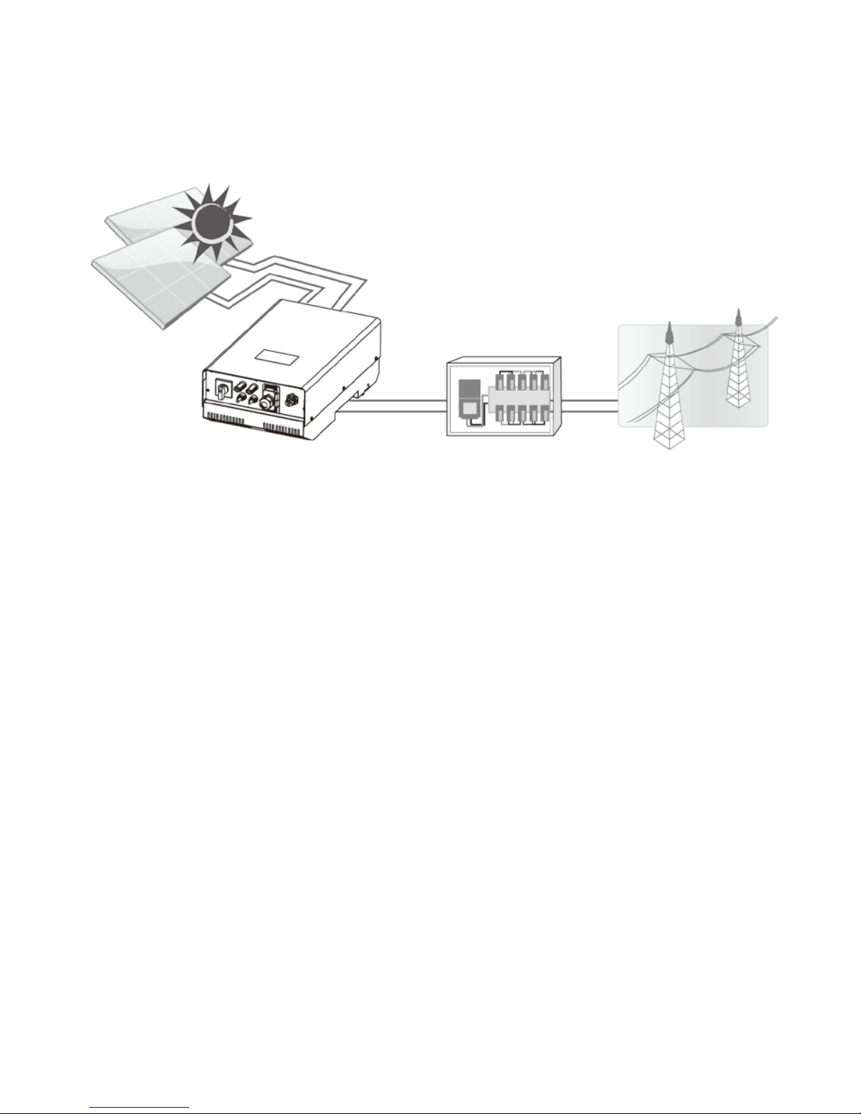
Figure 1 Basic PV System Overview
This inverter is only compatible with PV module types of single crystalline and poly crystalline.
And, only Class A-rated PV modules are acceptable to use. Do not connect any sources of
energy other than these two types of PV modules to the inverter. When designing the PV
system, ensure that the values comply with the permitted operating range of all components
at all times. See Figure 1 for a simple diagram of a typical PV system with the Inverter.
1-1. Affecting Factors for Performance of the Inverter
There are a lot of factors to influence the performance of this inverter.
Rating for PV Modules
PV modules are r at ed at ideal f acto ry conditions , such as spec ified illumination (1000 W/m2),
spectrum of the light and temperature (25 °C / 77 °F). This is called the STC (Standard Test
Condition) rating and is the figure that appears on the spec label of PV module. Generally
speaking, only around 60% to 70% of its peak STC-rated output will be produced from your
PV modules due to unpredicted environmental factors.
Temperature and Power Reduction
Environment temperature affects the power output of PV modules. Higher the temperature,
lower the power output of PV module. Comparing with pole-mounted PV module array,
roof-mounted PV module array generates less power due to less air circulation and excess
heat from roof top.
Distribution Box
Electric grids
PV inverter
PV module 1
PV module 2
(only for 5KW)
Page 4

2
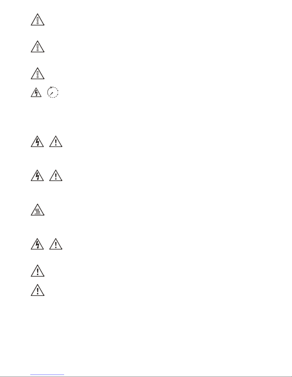
Conventions used:
WARNING! Warnings identify co ndit ions or practices that could result in personal injur y;
CAUTION! Caution identify conditions or practices that could result in damaged to the
unit or other equipment connected.
Important: The inverter will reduce its output generation to protect its electronic circuits
from overheating and any damage under high temper ature environment. For maximum power
output in high temperature, it’s recommended to mount the inverter in a shaded location with
good ventilation.
Angle of the Sun
The angle of the sun in relation to the PV ar ray surf ace—the arr ay orientatio n can dramatic ally
affect the PV arr ay output. The arr ay energy out put will vary depend ing on the time of da y and
time of year as the sun’ s angle in relation to the array changes. Sunlig ht outp ut de creases as
the sun approaches the horizons (such as in winter in Europe) due to the greater atmospheric
air mass it must penetr ate, reducing both the light i ntensity that strikes the arr ay’s surface and
spectrum of the light. In general, you can expect only four to six hours of direct sunlight per
day depending on what part of Europe the inverter is installed.
Partial Shade
Shading on a single PV module of the array will reduce the output power of the entire system.
Such shading can be caused by something as simple as the shadow of a utility wire or tree
branch on part of the array’s surface. This condition, in effect, acts like a weak battery in a
flashlight, reducing the total output, even though the other batteries are good. However, the
output loss is not pr oportionate to shad ing even a tiny bi t of shading w ill reduce t he PV power
to the inverter. The inverter is designed to maximize its power production in all of the above
situations using its proprietary MPPT algorithm.
Other Factors
Other factors to reduce power generation of a solar system are:
Dust or dirt on the modules
Fog or smog
Mismatched PV array modules, with slight inconsistencies in performance from one
module to another.
Inverter efficiency
Wire losses
Utility grid voltage
2. Important Safety Warning
Before using the inverter, please read all instructions and cautionary markings on
the unit and this manual. Store the manual where it can be accessed easily.
This manual is for qualified personnel. The tasks described in this manual may be performed
by qualified personnel only.
General Precaution-
Page 5
3
WARNING! Before installing and using this inverter, read all instructions and cautionary
markings on the inverter and all appropriate sections of this guide.
WARNING! Normally grounded conductors may be ungrounded and energized when a
ground fault is indicated.
WARNING! This inverter is heavy. It should be lifted by at least two persons.
CAUTION! Authorized service personnel should reduce the risk of electrical shock by
disconnecting both the AC and DC power from the inverter before attempting any
maintenance or cleaning or working on any circuits connected to the inverter. Turning off
controls will not reduce this risk. Internal capacitors can remain charged for 5 minutes after
disconnecting all sources of power.
CAUTION! Do not disassemble this inverter yourself. It contains no user-serviceable parts.
Attempt to service this inverter yourself may cause a risk of electrical shock or fire and will
void the warranty from the manufacturer.
CAUTION! To avoid a risk of fire and electric shock, make sure that existing wiring is in good
condition and that the wire is not undersized. Do not operate the Inverter with damaged or
substandard wiring.
CAUTION! Under high temperature environment, heat sink of this inverter could be hot
enough to cause skin burns if accidentally touched. Ensure that this inverter is away from
normal traffic areas.
CAUTION! Use only recommended accessories from installer. Otherwise, not-qualified tools
may cause a risk of fire, electric shock, or injury to persons.
CAUTION! To reduce risk of fire hazard, do not cover or obstruct the heat sink.
CAUTION! Do not operate the Inverter if it has received a sharp blow, been dropped, or
otherwise damaged in any way. If the Inverter is damaged, called for an RMA (Return Material
Authorization).
Page 6
4
3. Unpacking & Overview
3-1. Packing List
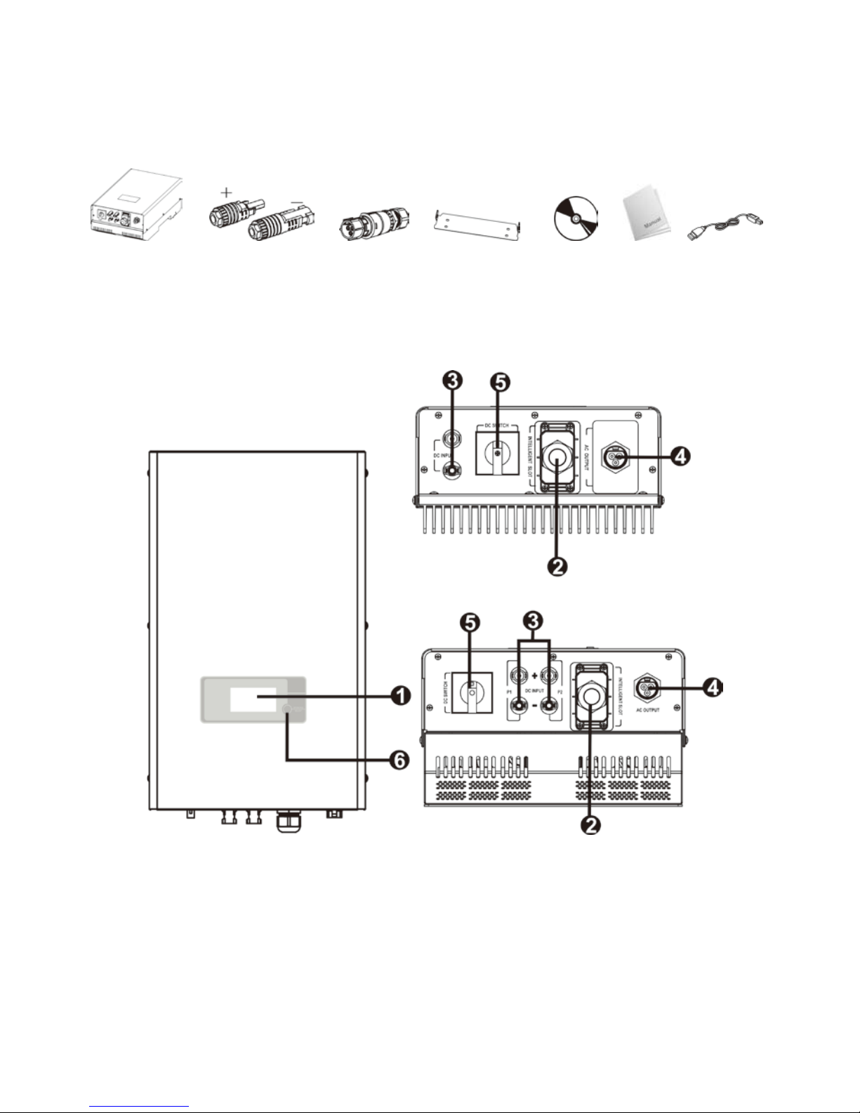
Before installation, please inspect the unit. Be sure that nothing inside the package is
damaged. You should have received the following items inside of package:
Inverter unit PV connectors* AC connector Mounting plate Software Manual USB cable
CD
*Note: 1 set of PV connectors for 3KW inverter and two sets of PV connectors for 5KW
inverter.
3-2. Product Overview
1) LCD display panel (Please check section 8 for detailed LCD operation)
2) Intelligent slot with USB communication port
3) Connectors for solar modules
4) AC output terminal
5) DC switch (Option)
6) Operation button
3KW inverter
5KW inverter
Page 7
5
WARNING!! Remember that this inverter is heavy! Please be carefully when lifting out
from the package.
4. Installation
4-1. Selecting Mounting Location
Consider the following points before selecting where to install:
Do not mount the inverter on flammable construction materials.
Mount on a solid surface
Although the unit is fitted with UV resistant components, direct exposure to sunlight
may cause a power reduction due to excessive heating.
This inverter can make noises during oper ation which may be perceived as a nuisance in
a living area.
Install this inverter at eye level in order to allow the LCD display to be read at all times.
For proper air circulation to dissipate heat, allow a clearance of approx. 20 cm to the
side and approx. 50 cm above and below the unit.
Dusty conditions on the unit may impair the performance of this inverter.
The ambient temperature should be between -25°C and 60°C to ensure optimal
operation.
The recommended installation position is to be adhered to (vertical).
Unused DC connectors and interfaces must be sealed with sealing plugs to ensure
protection class IP65 for the whole system (inverter & cables).
This inverter is designed with IP65 for outdoor applications with high humidity.
4-2. Mounting Unit with Wall Mounting Bracket
Please utilize the delivered mounting plate for problem-free installation of the solar inverter.
Installation to the wall should be implemented with the proper screws. Mount the w all bracket
so that the solar inverter can be easily attached to the wall. After that, the device should be
bolted on securely.
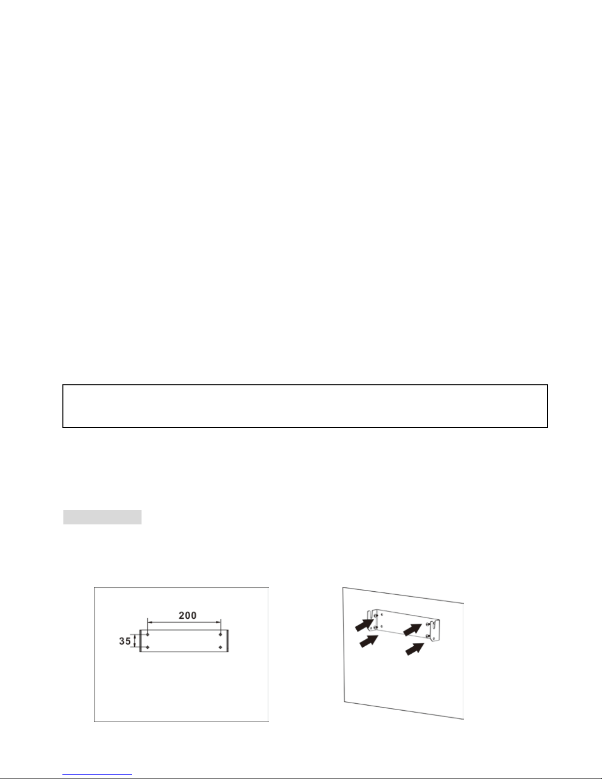
3KW inverter
1. Employ the mounting plate as a t emp late
for marking the positions of the
boreholes
2. Mount the mounting plate with
appropriate screws (M5x4pcs,SUS304
or M10x2pcs, SUS304) into four or two
holes to fix the plate in place
Page 8
6
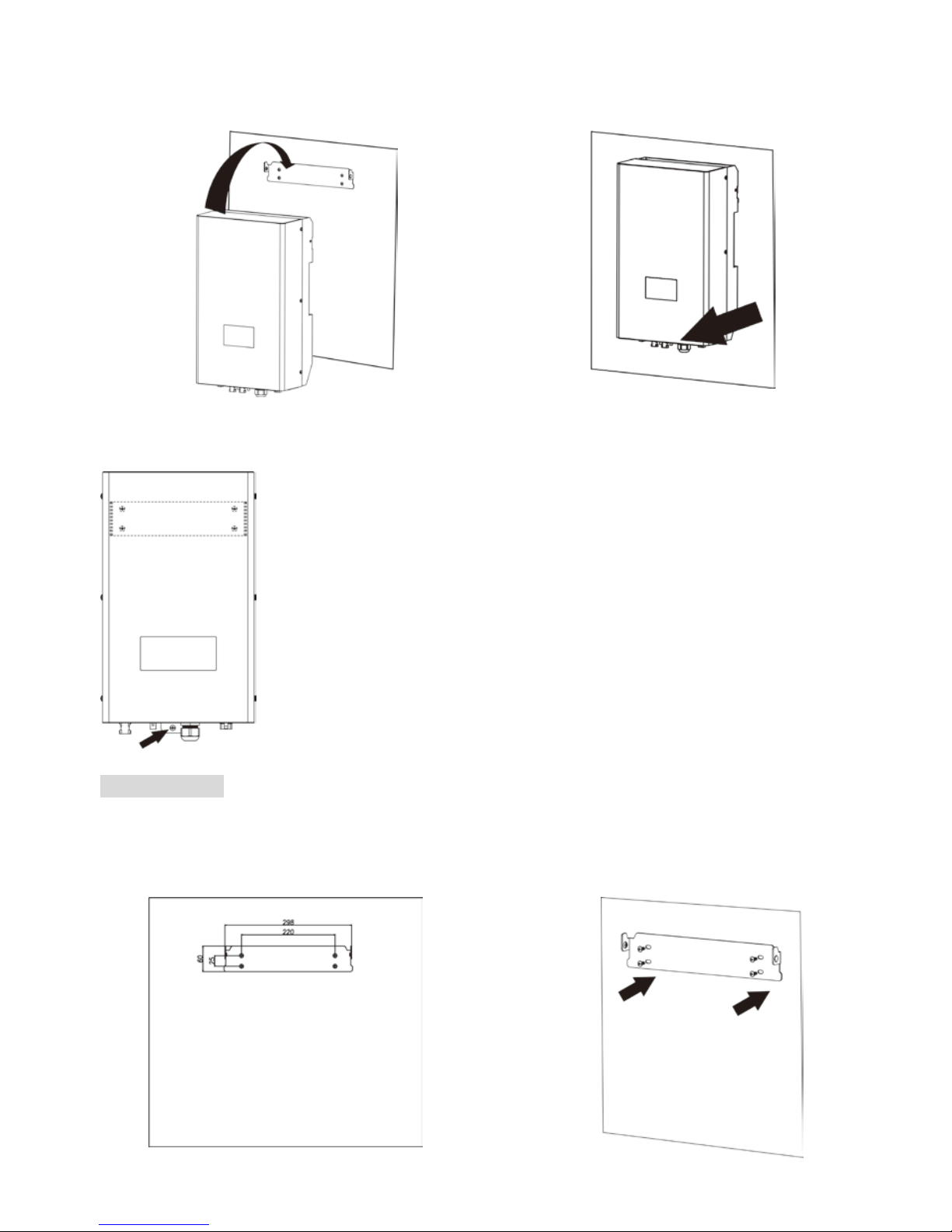
3. Follow the below figure to place the solar
inverter onto the mounting plate.
4. Check if the solar inverter is firmly
secured.
5. Screw the inverter in position by screwing the supplied M5 screw, located on the
underside of the enclosure. Refer to blow chart.
5KW inverter
1. Employ the mounting plat e as a t emp late
for marking the positions of the
boreholes
2. Mount the mounting plate with
appropriate screws (M5x4pcs,SUS304
or M10x2pcs, SUS304) into four or two
holes to fix the plate in place
Page 9
7
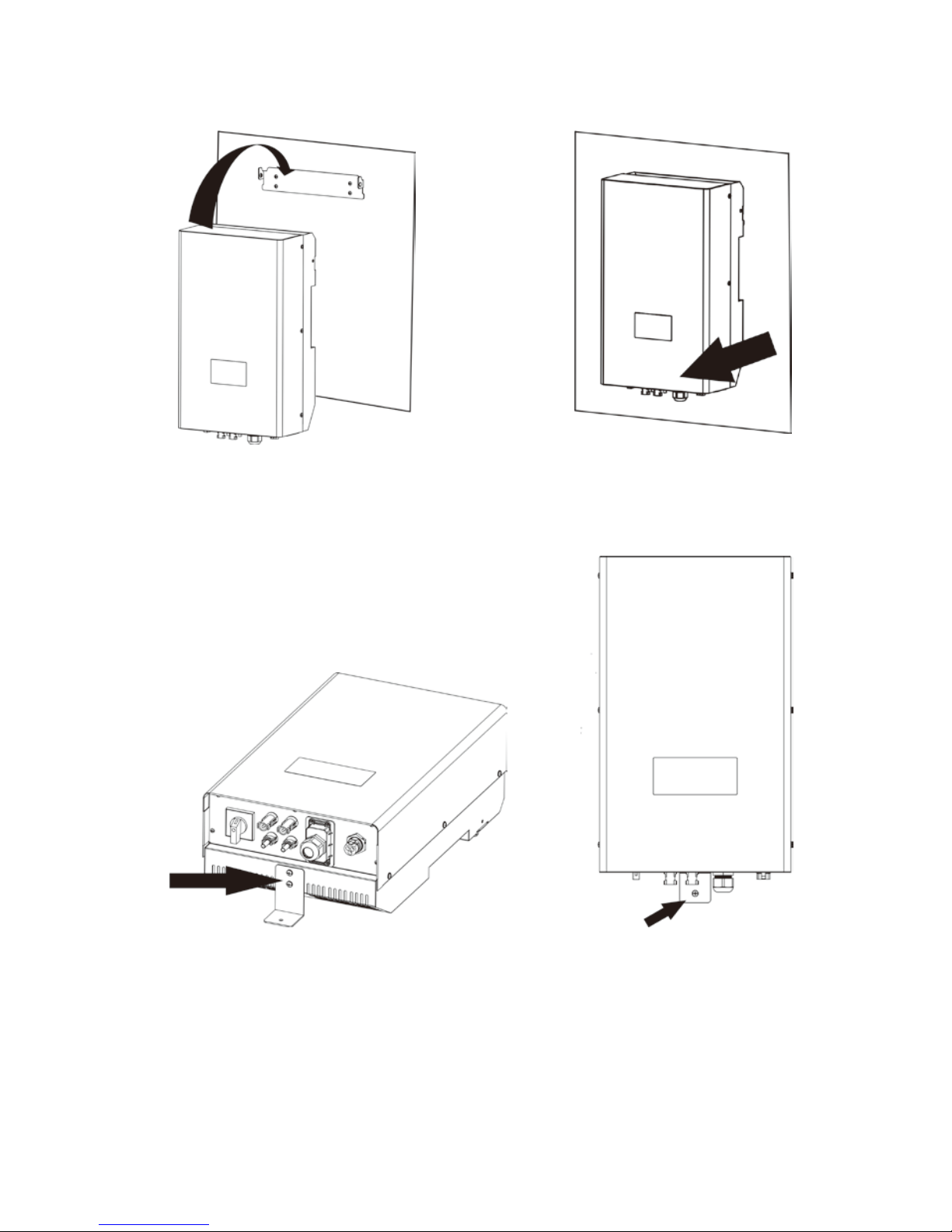
3. Follow the below figure to place the solar
inverter onto the mounting plate.
4. Check if the solar inverter is firmly
secured.
5. Attach small mounting plate to the unit with supplied 2 pieces of M4 screws. Then, screw
the inverter in position by screwing one M5 screw, located on the underside of the
enclosure. Refer to blow chart.
Page 10
8
5. Grid (AC) Connection
5-1. Preparation
Before connecting to AC utility, please install a separate AC circuit breaker between inverter
and AC utility. This will ensure the inverter can be securely disconnected under load.
NOTE1: Although this inverter is equipped with a fuse (F1 point on PCB, 3KW: 250VAC/20A;
5KW: 250VAC/30A), it’s still necessary to install a separate circuit breaker for safety
consideration. Please use 250VAC/20A circuit breaker for 3KW and 250VAC/30A circuit
breaker for 5KW.
NOTE2: If you want to add a manual RCMU, it shall be type B.
WARNING! It's very important for system safety and efficient operation to use appropriate
cable for grid connection. To reduce risk of injury, please use the proper recommended cable
size as below.
Suggested cable requirement for AC wire
Model External
Diameter(mm)
Conductor cross-section
(mm
2
)
AWG no. Temperature
3KW & 5KW
≦4.5
≥3.3 ≤12 125°C
5-2. Connecting to the AC Utility
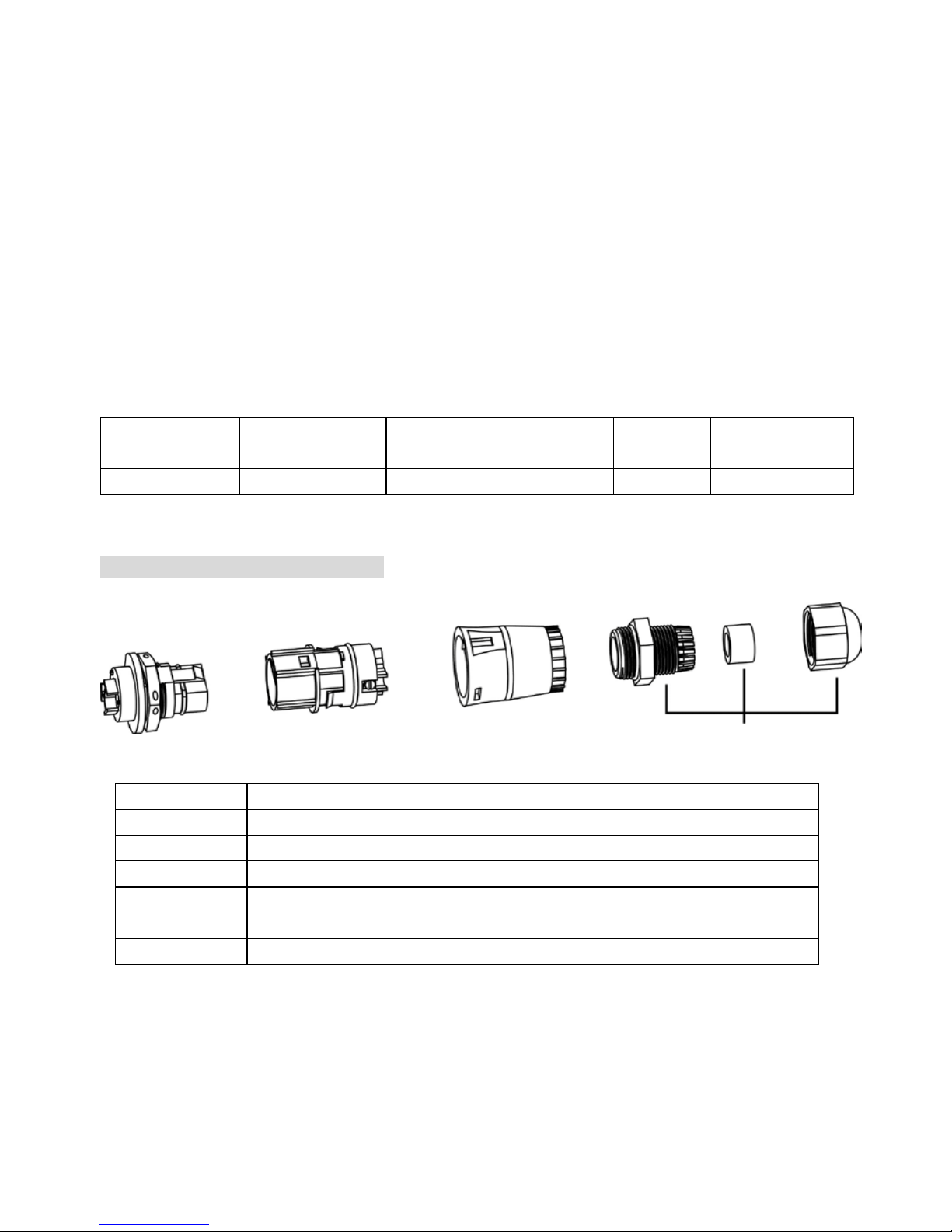
Overview of AC Connection Socket
Component Description
A AC output terminal on the inverter
B Socket element
C Protective element
D Threaded sleeve
E Sealing nut
F Pressure dome
Step 1: Check the grid voltage and frequency with an AC voltmeter. It should be the same to
“VAC” value on the product label.
Step 2: Turn off the circuit breaker.
Step 3: Insert sealing nut (E) inside of threaded sleeve (D). Then, screw pressure dome (F)
tightly onto the assembled threaded sleeve. (Refer to Chart 1)
B
A
C
D E
F
Cable gland
Page 11
9
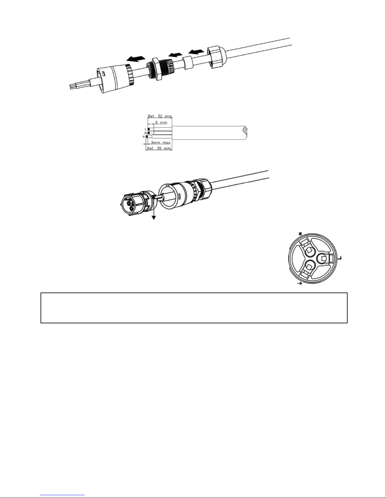
Step 4: Thread the protective element (C) with assembled cable gland over the utility cable.
(Refer to Chart 1)
Chart 1
Step 5: Remove insulation sleeve 8 mm fo r three conductors. And shorten phase L and neutral
conductor N 3 mm.
Step 6: Insert utility cable thr ough socket element (B) and tighten the screw to fix utility cable.
And push protective element (C) onto the socket element (B) until it audibly snaps into pl ace.
screw
Step 7: Connect wires according to polarities indicated on AC output
terminal on the inverter and tighten the screws after connection.
L→LINE (brow n or black)
G→Ground (yellow -green)
N→Neutral (blue)
Step 8: Twist the gland so that the cable is firmly connected.
CAUTION: To prevent risk of electric shock, ensure the ground wire is properly earthed
before operating the solar inverter.
C
D
E
F
B
Page 12
10
6. PV Module (DC) Connection
CAUTION: Do NOT connect battery or DC source to PV connectors. Otherwise, it will cause
inverter damage.
CAUTION: Before connecting to PV modules, please install separately a 2P circuit breaker
for 3KW, 4P or two 2P DC circuit b reakers for 5KW between inverter and PV modules.
NOTE: Please use 600VDC/15A circuit breaker for 3KW and 600VDC/17A circuit breaker for
5KW.
Please follow below steps to implement PV module connection:
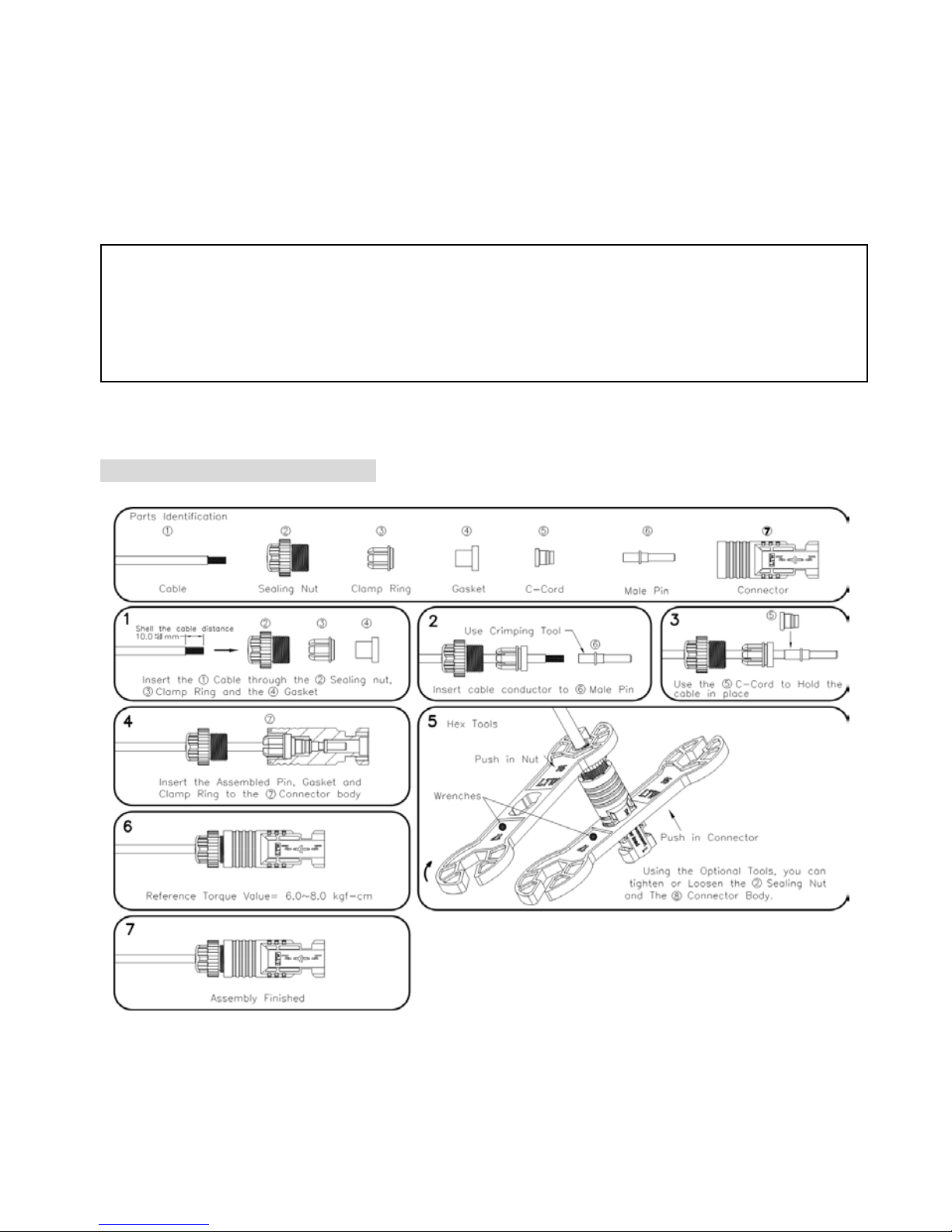
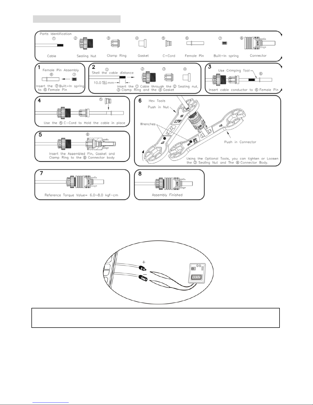
Step 1: Assemble provided PV connectors into PV modules by following below steps.
Negative terminal connection
WARNING: This in verter is only compatible to two types of PV modules: single crystalline
and poly crystalline. To avoid any malfunction, do not connect any PV modules with
possibility of leakage current to the inverter.
CAUTION: To avoid any damage to the unit, be sure DC switch or circuit breakers are all
Page 13
11
Positive terminal connection
Step 2: Check the input voltage of PV array modules. The acceptable input voltage of solar
inverter is 125VDC - 500VDC. If this system is only applied with one string of PV array, then
please make sure that the maximum current load of each PV input connector is 13A for 3KW
and 15A for 5KW. F or 5KW inverter, you may serial connect two sets of PV modules as one and
the maximum current load will not exceed 30A.
Step 3: Disconnect the circuit breaker.
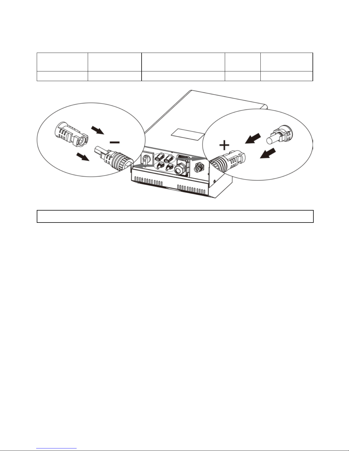
Step 4: Check correct polarity of connection cable from PV modules and PV input connecto rs.
Then, connect positive pole (+) of connection cable to positive pole (+) of PV input connector.
Connect negative pole (-) of connection cable to negative pole (-) of PV input connector.
CAUTION:
Exceeding the maximum input v o l tag e can d estr oy the unit!! Check the system
before wire connection.
Page 14
12
WARNING! It's very important for system safety and efficient operation to use appropriate
cable for DC connection. To reduce risk of injury, please u s e the proper recommended cable
size as below.
Suggested cable requirement for DC wire
Model External
Diameter(mm)
Conductor cross-section
(mm
2
)
AWG no. Temperature
3KW & 5KW
≦6.0
≥3.3 ≤12 125°C
CAUTION: Never directly touch terminals of the inverter. It w
ill cause lethal electric shock.
Page 15
13
7. Communication
This inverter is equipped with a slot for communication interfaces in order to communicate
with a PC with corresponding software. This intelligent slot i s suitable to install with
RS-232/USB combo card and Modbus card. Follow below procedure to connect
communication wiring and install the software.
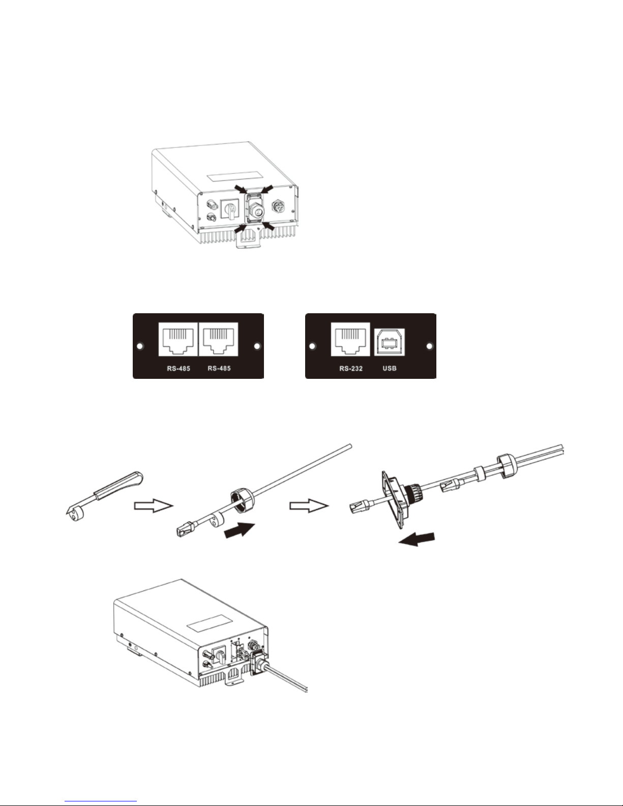
Step 1: Take out communication cover by removing 4 screws.
Step 2: Assemble and connect communication cable.
No matter this inverter is equipped with RS-232/USB combo card or Modbus card, you will see
two ports available after removing the cover.
Modbus card RS-232/USB combo card
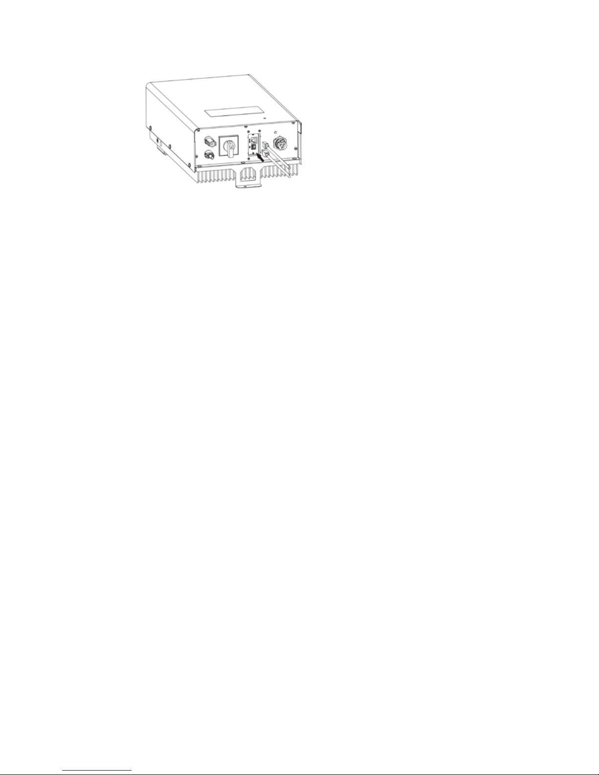
If it’s equipped with Modbus card, you have to assemble communication cable through cable
gland first. Please cut the sealing nut and insert supplied USB cable through sealing nut as
shown in below chart. Insert the assembled cable through pressure dome and screw tightly
cable gland to the cover.
Then, insert this cable through cover to connect RS-485 port of this inverter and your PC as
below chart.
Modbus card connection
Page 16
14
If it’s equipped with RS-232/USB combo card, you may use s upplied USB cable to connect USB
port of this inverter and your PC. Or you may use one network cable (RJ-45) to connect
RS-232 port of this inverter and your PC.
RS-232/USB combo card connection
Step 3: Install monitoring software in your PC.
Please insert CD into your computer and install monitoring software in yo ur PC . Fo l low belo w
steps to install software.
1. Follow the on-screen instructions to install the software.
2. When your computer restarts, the monitoring software will appear as shortcut icon located
in the system tray, near the clock.
Step 4: Initial your monitoring software and extract data through communication port. After
completing data acquisition, please put the communication port back to the unit.
Page 17
15
8. Commissioning
Step 1: Check the following requirements before commissioning:
Ensure the inverter is firmed secured
Check if the open circuit DC voltage of PV module meets requirement (Refer to Section
6)
Check if the open circuit utility voltage of the utility is at approximately same to the
nominal expected value from local utility company.
Correct connection to grid
Full connection to PV modules
Unused DC input connectors are sealed with supplied sealing plugs.
AC circuit breaker and DC circuit breaker are installed correctly.
Step 2: After switching on the DC circuit breakers, it will display “No Utility” in the LCD screen.
Then, switch on the AC circuit breakers. After 60 seconds, the system will automatically
connect to the grid. Then:
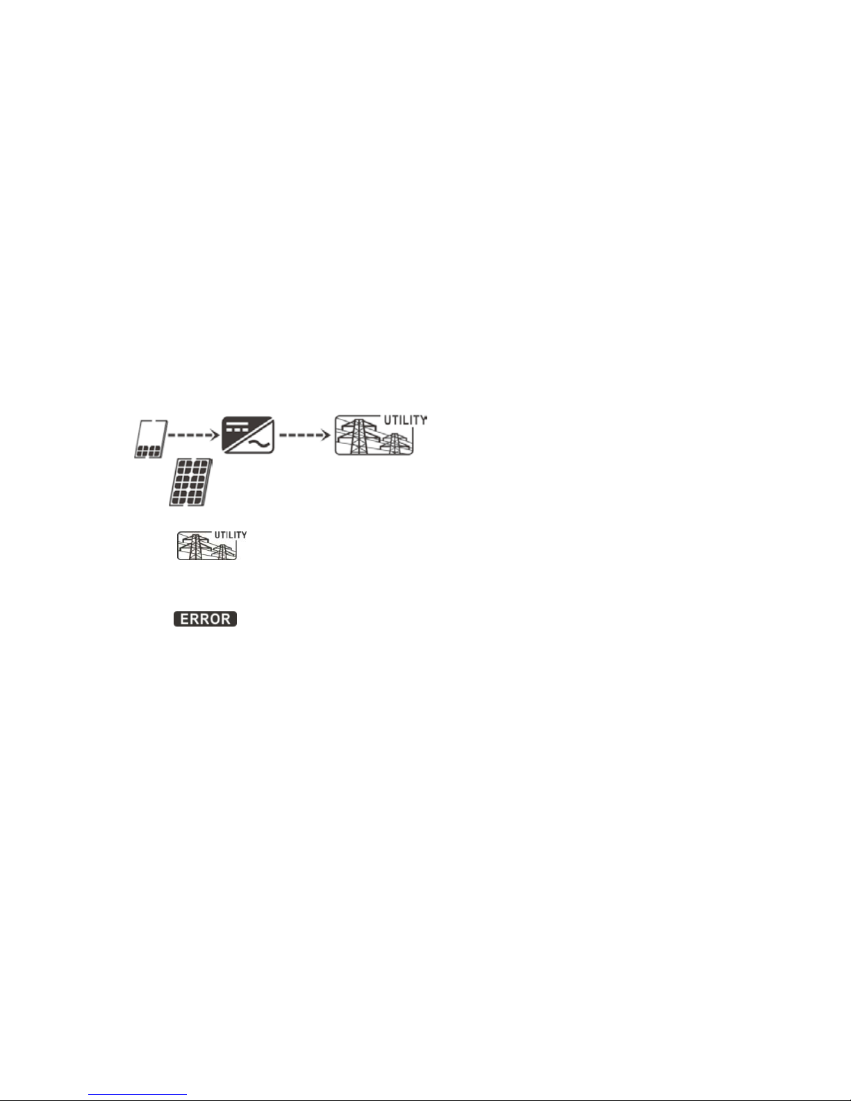
If inverter icon is in the LCD display like below, commissioning has been successfully.
Or, if
icon flashes, there is insufficient radiation and the inverter is in standby
mode. Wait for sufficient radiation.
Or, if icon flashes, the grid voltage or frequency is beyond acceptable range
and the inverter is in standby mode. Wait for grid voltage or frequency to return to
acceptable range.
Or if
icon flashes, there has been an error. Please check chapter 11 for trouble
shooting. If the problem still resists, please inform your installer.
Step 3: After the inverter is successfully on, please calibrate the time and date o f the inverter
via monitoring software. Please check software manual for the details.
Page 18
16
9. Operation
9-1. Interface
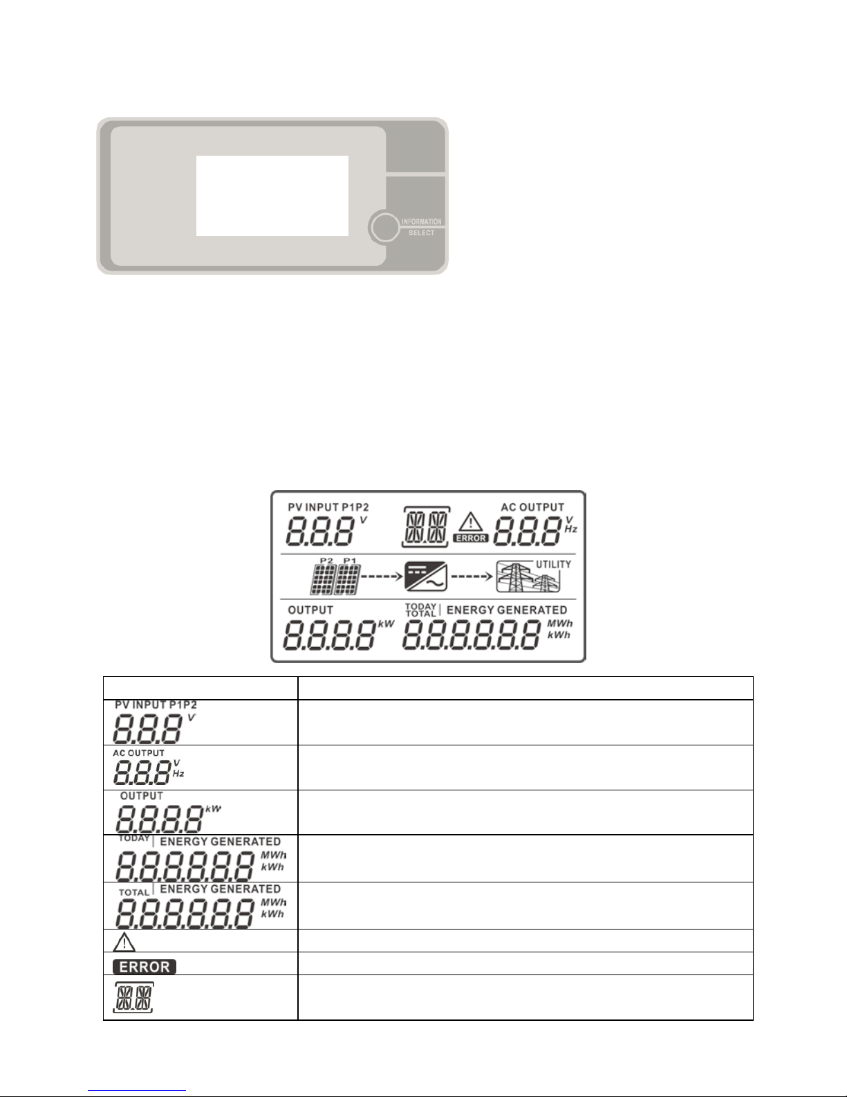
This LCD panel shows current status and value of your system. This display is operated by
Information/SELECT button.
NOTICE: To accurately monitor and calculate the energy generation, please calibrate the
timer of this unit via software every one month. For the detailed cali br ation, please check the
user manual of bundled software.
9-2. LCD Information Define
Display Function
Indicates input voltage of PV module 1 or PV module 2.
P1: PV module 1, P2: PV module 2, V: voltage
Indicates AC output voltage or frequency.
V: voltage, Hz: frequency
Indicates current feeding power.
Indicates energy generated today.
Indicates total energy generated so far.
Indicates that the warning occurs.
Indicates that the fault occurs.
Indicates fault code in fault mode or WR for warning
situation.
Page 19
17
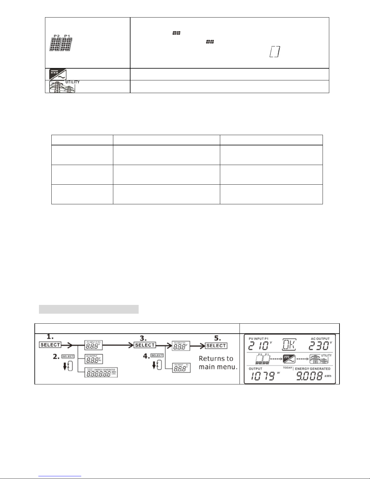
Indicates PV module status.
Each
indicates 150VDC. When input voltage is
below 100VDC,
icon will flash.
When PV module is not connected, icon will
flash.
Indicates the Inverter circuit is working.
Indicates grid.
9-3. Operation Button
The INFORMATION/SELECT button controls LCD settings and has three functions.
Function Operation Description
Information
changes
Press the button once To jump to next selection or
decrease value.
Query Menu Press and hold the but ton for 2
seconds
To enter query menu
Selection
confirmed
Press and hold the button f or 2
seconds
To confirm selection or
value entry in query menu.
NOTE: If backlight shuts off, you may activate it by pressing any button.
9-4 Query Menu Operation
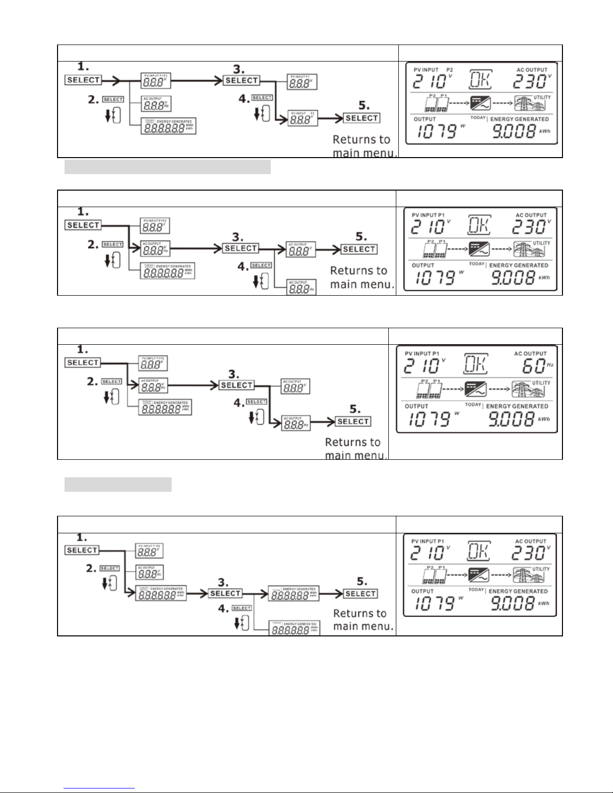
This display shows current values of your system. These displayed values can be changed in
query menu via button oper ation. Press “INFORMATION/SELECT” button to enter query menu.
There are three query selections:
Input voltage of PV module 1 or PV module 2
Frequency or voltage of AC output
Power generation today or total power generation since installation.
Input voltage of PV module
Input voltage of PV module 1
Procedure LCD Display
Page 20
18
Input voltage of PV module 2 (only available for 5KW)
Procedure LCD Display
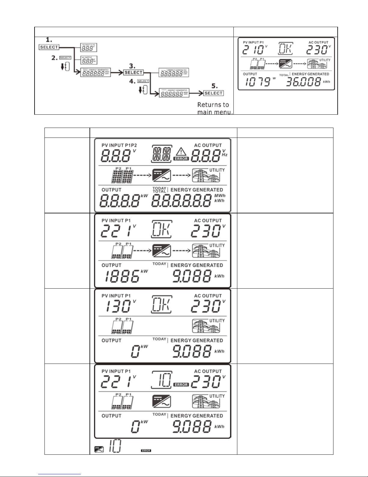
Frequency or voltage of AC output
Voltage of AC output
Procedure LCD Display
Frequency of AC output
Procedure LCD Display
Power generation
Power generation today
Procedure LCD Display
Page 21
19
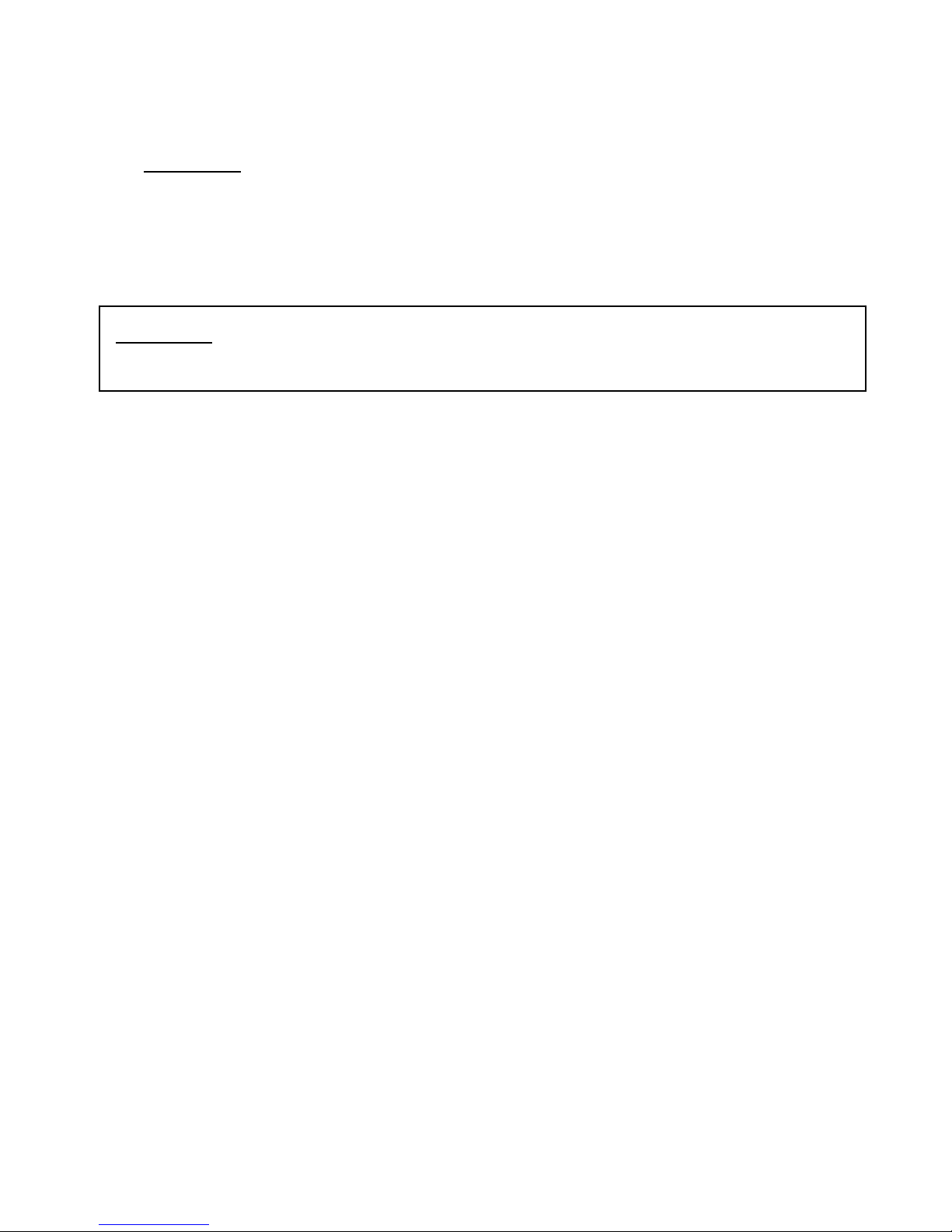
Total power generation since installation
Procedure LCD Display
9-5. Operation Mode & Display
Mode LCD Display Description
Power on
mode
The inverter is initializing.
Grid mode
The inverter is feeding
power to the grid.
Standby
mode
The inverter is waiting for
the DC voltage to reach a
certain level so that it can
start feeding the grid.
Fault mode
, and icons will flash.
An error occurs inside of
the inverter. Please inform
your installer.
Page 22
20
WARNING: There are no user-replaceable parts inside of the inverter. Do not attempt to
service the unit yourself.
10. Maintenance & Cleaning
Check the following points to ensure proper operation of whole solar system at regular
intervals.
Heat sink of the inverter should be cleaned from dust.
WARNING: Although the inverter is designed in sealed IP65 en closure, it is not
recommended to use a pressure washer to clean the inverter, or use other high pressure
cleaning methods that could allow water or moisture to enter the unit.
Clean the PV modules, during the cool time of the day, whenever it is visibly dirty.
Periodically inspect the system to make sure that all wires and supports are securely
fastened in place.
Page 23
21
11. Trouble Shooting
When there is no information displayed in the LCD, please check if PV module connection is
correctly connected.
11-1. Warning Situation
There are 4 situations defined as warnings. When a warning situation occurs,
icon will
flash and the fault code area will display “WR” wordings.
No PV module is connected flash failure
Inverter initial failure Fan failure (Only for 5KW)
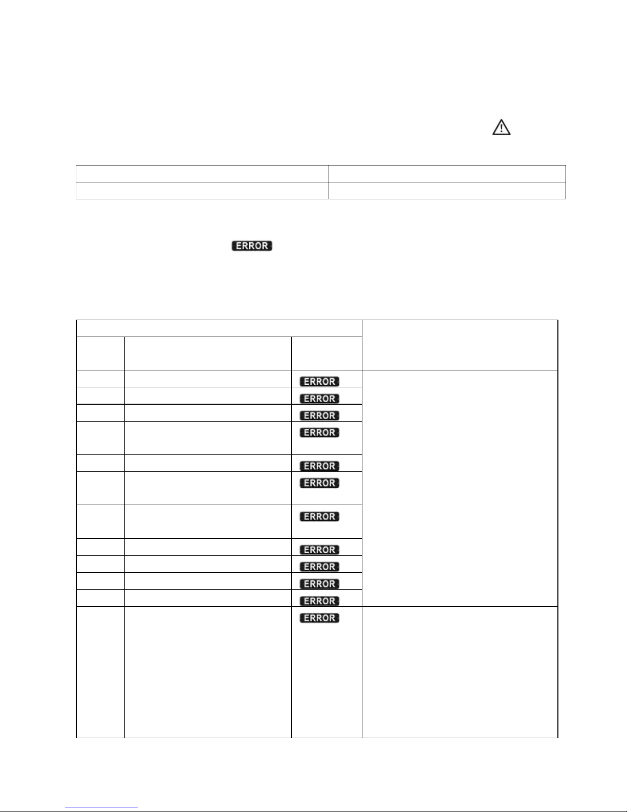
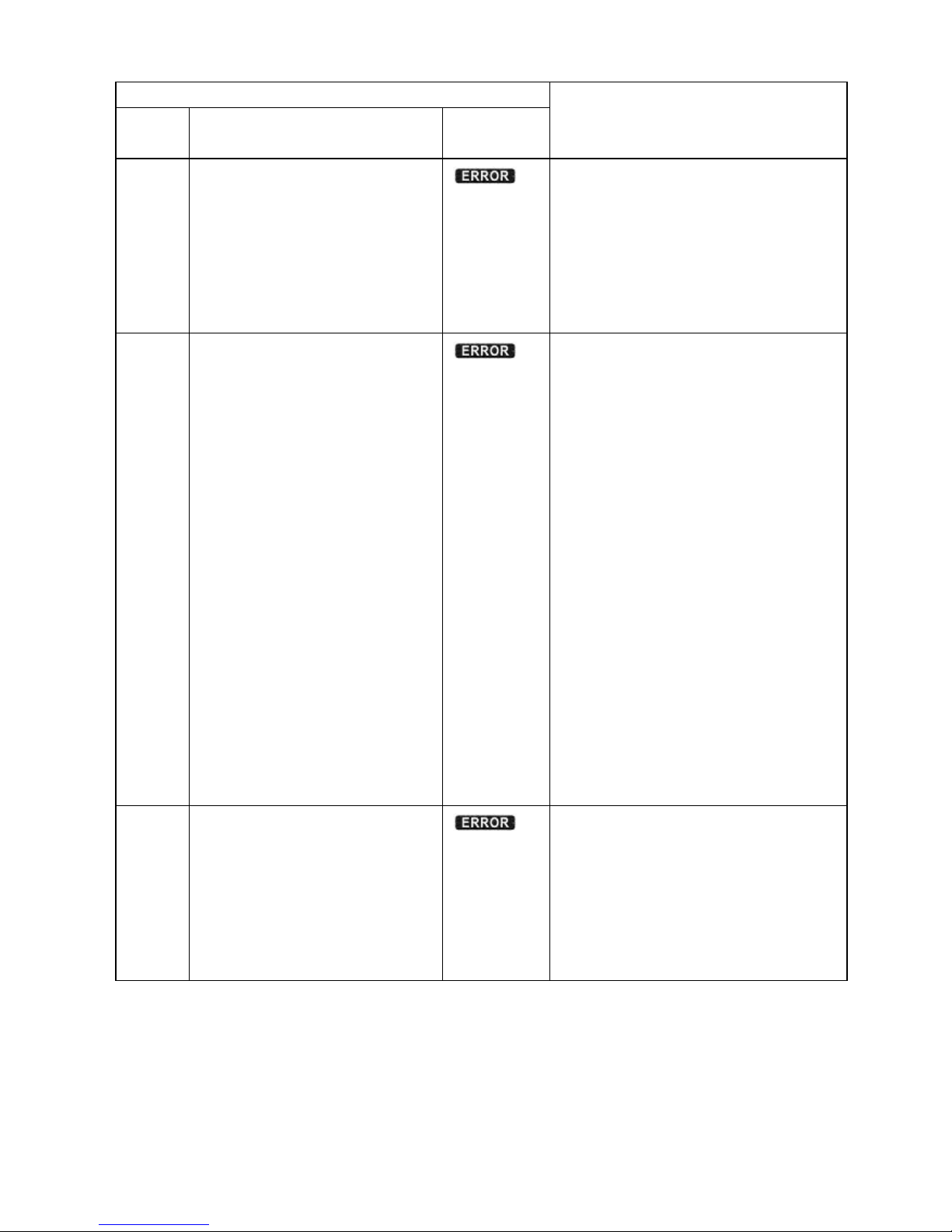
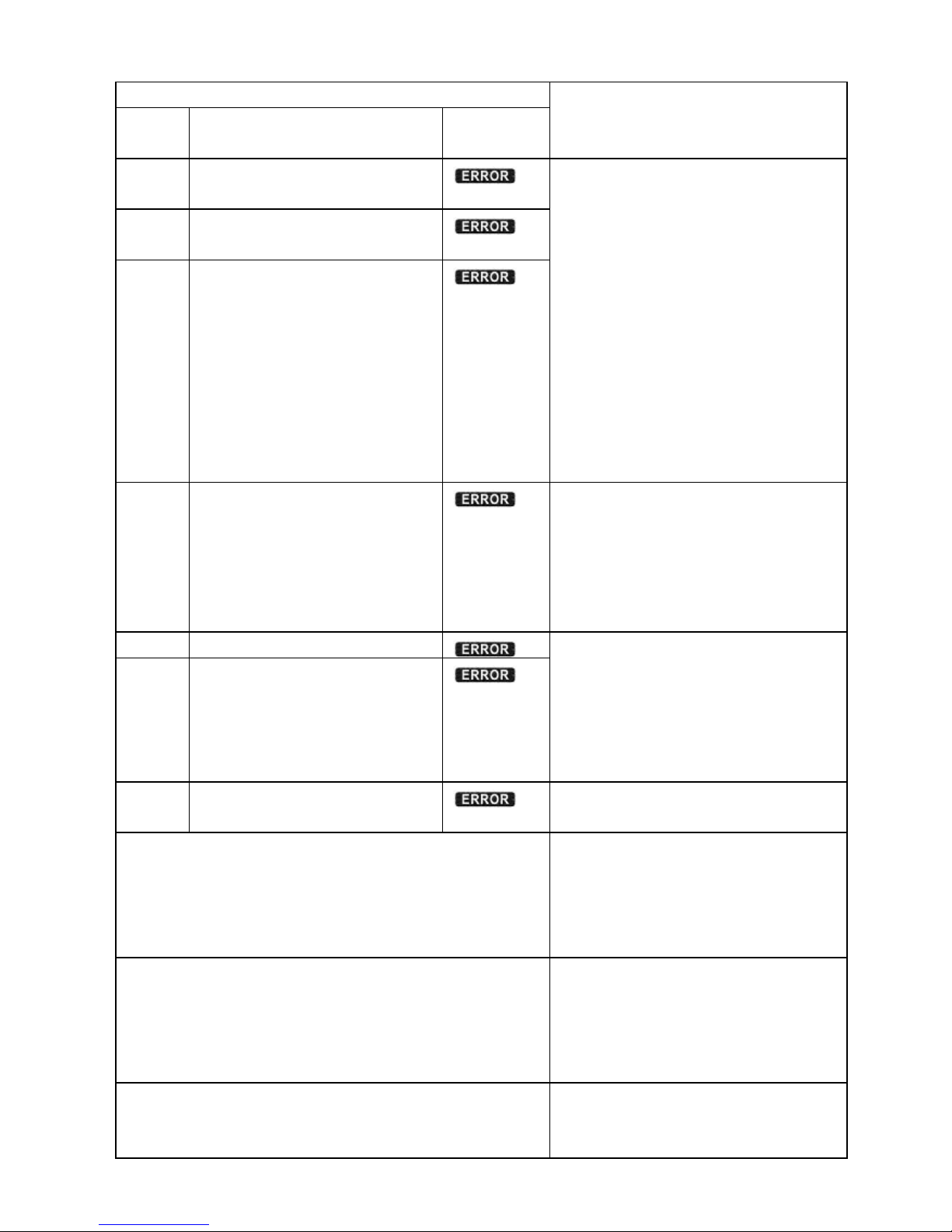
11-2. Fault Reference Codes
When a fault occurs, the icon
will flash as a reminder. See below for fault codes for
reference.
Note: When the fault occurs, it will be recorded in the flash, Max 9 faults can be saved. You
can use Solar Power to read the fault data log. The detail information please refer to Solar
Power Manual 4.3.3.
Situation
Solution
Fault
Code
Fault Event
Icon
(flashing)
1 Over voltage on Bus
1. Disconnect AC circuit breaker
first. Then, disconnect DC
circuit breaker.
2. Until LCD screen completely
shuts down, turn on DC
breaker first. It will show “No
Utility” in LCD screen. Then,
turn on AC breaker. After 60
seconds, the system will
automatically connect to the
grid.
3. If the error message still
remains, please contact your
installer.
2 Under voltage on Bus
3 Time out for Bus soft start
4 Time out for Inverter soft
start
5
Inverter over current
7 Relay or inverter voltage
detector fault
8 Output current sensor
failure
10 Power failure
11 DC input over current
14
Inverter DC current over
16 GFCI sensor failure
6 Over temperature
1. The internal temperature is
higher than specified
temperature.
2. Leave inverter to be cooled
to room temperature.
3. If the error message still
remains, please contact your
installer.
Page 24
22
Situation
Solution
Fault
Code
Fault Event
Icon
(flashing)
9 High voltage on PV module
1. Check if the open circuit
voltage of PV modules is
higher than 500VDC.
2. If PV open circuit voltage is
less than 500VDC and the
error message remains,
pelase contact your installer.
12 GFCI failure
1. The ground voltage is too
high.
2. Please disconnect AC breaker
first and then DC breaker.
Check if grounding is
connected properly after LCD
screen completely shuts
down.
3. If grounding is correctly
connected, turn on DC
brearker. After it displays “No
Utility” in LCD screen, turn
on AC breaker. After 60
seconds, the system will
automatically connect to the
grid.
4. If the error message still
remains, please contact your
installer.
13 PV insulation failure
1. Check if the impedance
between positive and
negative poles to the ground
is greater than 1MΩ.
2. If the impedance is lower
than 1MΩ, please contact
your installer.
Page 25
23
Situation
Solution
Fault
Code
Fault Event
Icon
(flashing)
15 Line value consistent fail
between MCU & DSP
1. Please disconnect AC breaker
first and then disconnect DC
breaker.
2. After LCD screen is
completely off, turn on DC
breaker. Until it shows “No
Utility” in LCD display, turn
on AC breaker. After 60
seconds, the system will
automatically connect to the
grid.
3. If error message remains,
please contact your installer.
17 Connection failure between
MCU & DSP
18 Communication failure
between MCU & DSP
19 Ground loss
1. Check if the inverter is
connected to the ground.
2. If ground is properly
connected and the error
message remains, please
contact your installer.
22 Grid voltage loss
1. Grid loss is detected or grid
input is not within
acceptable range.
2. If grid is ok but the error still
remains, please contact
your installer.
23 Grid frequency loss
24 Islanding is detected.
Grid is abnormal. Please wait for
grid to return.
No display in LCD screen. 1. Check input voltage of PV
modules.
2. If input voltage is higher
than 150VDC, please
contact your installer.
Time display in LCD screen changes quickly or
slowly.
1. Please calibrate the timer
via software.
2. If the problem remains after
calibration, please contact
your installer.
Inverter is turned on and turned off in turns. 1. It’s normal situation due to
insufficient radiation in the
short-term time.
Page 26
24
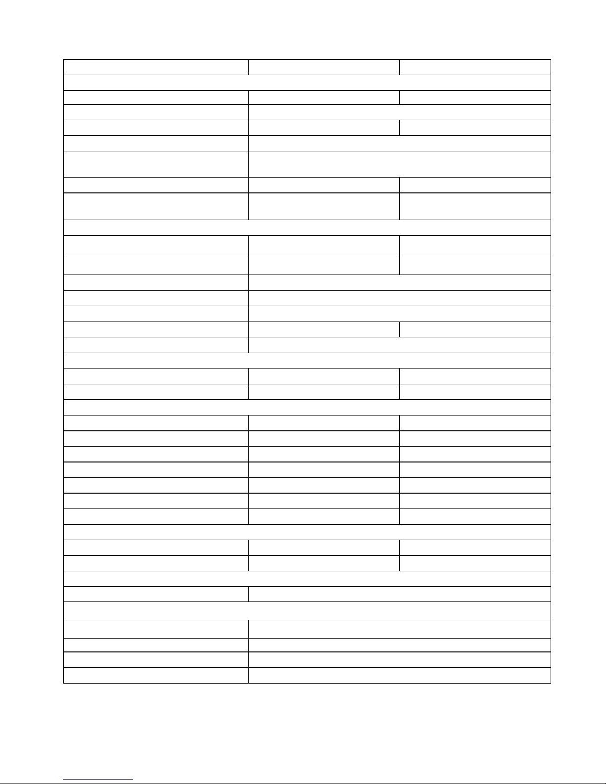
12. Specifications
MODEL
SP3000 Vigor
SP5000 Vigor
INPUT (DC)
Max. DC Power 3300 W 5000W
Maximum DC Voltage 500 VDC
MPP Voltage Range 250 VDC ~ 500 VDC 180 VDC ~ 500 VDC
DC Nominal Voltage 370 VDC
Start-up Voltage / Initial Feeding
Voltage
125VDC / 150VDC
Maximum Input Current 1 x 13 A 2 x 15 A
Number of MPP Trackers / Strings per
MPP Tracker
1 / A: 1 2 / A: 1; B: 1
OUTPUT (AC)
AC Nominal Power 3000 W 4600 W
Maximum AC Apparent Power 3000 VA 4600 VA
Nominal AC Voltage / Range** 230 VAC / 184 VAC ~ 264 VAC
AC Grid Frequency 50 Hz / 60 Hz
AC Grid Frequency Range** 47.5~ 51.5 Hz
Nominal Output Current 13A 20 A
Power Factor @ > 50% load > 0.99
EFFICIENCY
Maximum Efficiency @ Nominal Voltage
97% 97%
European Efficiency @ Nominal Voltage
96% 96.5%
PROTECTION
DC Reverse-Polarity Protection Yes Yes
Ground Fault Monitoring Yes Yes
Grid Monitoring Yes Yes
AC Short Circuit Protection Yes Yes
Over Current Protection 30 A 50 A
Inrush Current 17 A / 1s 25 A / 1s
Maximum Output Fault Current 60 A / 10ms 100 A / 10ms
PHYSICAL
Dimension, D X W X H (mm) 450 x 270 x 155 515 x 310 x 185
Net Weight (kgs) 12.7 20.5
INTERACE
Intelligent Slot
USB & RS-232 card / Optional SNMP & Mod bus card
ENVIRONMENT
Protection Degree
IP65/Pollution Degree Ⅲ
Humidity 0 ~ 100%
Operating Temperature
-25°C to 60°C*
Altitude
0 ~ 1000 m
* When temperature is above 80°C, the unit will de-rate according to the below formula:
P=P
Rating
x [110%-(T-80)x10%].
** The grid voltage and frequency range may vary depending on different country grid standard. And these can be
changed through So larPower software.
 Loading...