

Page 1

SC-Max series
Solar Charge Controller
30A/40A/50A/60A
User Manual
Page 2

Contents
1 Description of function
2 Safety Instructions and Waiver of Liability
2.1 Safety
2.2 Liability Exclusion
3 Optional
3.1 Remote display unit
3.2 Remo te tem peratur e sens or
Dimens ions
4
5 Instal lati on
5.1 Moun ting l ocation r equi rements
5.2 Fast enin g the solar c harg e control ler
5.3 Prep arat ion of wiri ng
5.4 Conn ecti on
5.5 Grou ndin g
6 Indica tion o f Status
7 Ope rat ing th e solar cha rge co ntrolle r
7.1 F acto ry Pre -Set co nfig urat ions
7.2 Main M enu
7.3 Menu Conf (System module settings)
7.4 Menu Prog (System parameter settings)
7.5 Menu Load (Load mode settings)
7.6 Menu Logg (Inquiry of internal data logger)
7.7 Example of configuration
7.7 .1 Bat tery t ype
7.7 .2 Res et to Factory P re-S et Con figu ration
8 Safety Measures
8.1 E lect roni c Short Circu it Saf ety
8.2 H ardw are Sa fety
8.3 S afet y Feat ures
9 Malfunctions and Errors
10 Technical Data
P 1
P 1
P 1
P 1
P 1
P 1
P 1
P 2
P 2
P 2
P 2
P 2
P 2
P 3
P 3
P 4
P 5
P 5
P 5
P 6
P 6
P 8
P 9
P 10
P 10
P 10
P 11
P 11
P 11
P 11
P 12
P 13
Page 3

Dear Clients,
Thanks for selecting the SC- Max series solar controller. Please take the time to read this user manual, this will
help you to make full use of many advantages the controller can provide your solar system.
This manual gives important recommendations for installing, program, using and so on. Read it carefully in your
own interest please.
1. Description of function
With your new Max controller you own a state-of-the
art device which was developed according to the latest
available technical standards. It comes with a number
of outstanding features, such as:
LCD display
One year's data memory
12V/24V automatic recognition
External temperature sensor, make the temperature
compensation more accurate
Perfect EMC design
Many choices of battery type, working mode and
protection
Four stage PWM charge way: fast, boost, equalization,
float
Full automatic electronic protect function
3. Optional
3.1 Remote display unit
Remote display unit can display system information,
failure information and one year's charge and discharge
data.
3.2 Remote temperature sensor
Acquisition the ambient temperature of the battery, which
can be accurate compensation charge values, standard
wire length is 2 meters (can also be customized according
to user needs).
2.Saf ety instr uctions and wa iver
of liab ility
2.1 Safety
①The solar charge controller may only be used in
PV systems in accordance with this user manual
and the specifications of other modules
manufacturers. No energy source other than a solar
generator may be connected to the solar charge
controller.
②Batteries store a large amount of energy, never
short circuit a battery under all circumstances.
We strongly recommend connecting a fuse
directly to the battery to protect any short circuit
at the battery wiring.
③Batteries can produce flammable gases. Avoid
making sparks, using fire or any naked flame.
Make sure that the battery room is ventilated.
④Avoid touching or short circuiting wires or
terminals. Be aware that the voltages on special
terminals or wires can be as much as twice the
battery voltage. Use isolated tools, stand on dry
ground, and keep your hands dry.
⑤Keep children away from batteries and the
charge controller.
Liabil ity Ex clusion
2.2
The m anu fact urer shal l not be l iable for
damage s, esp ecially o n the ba ttery, caused
by use oth er tha n as intend ed or as m entione d
in th is ma nual o r if the reco mmen dations o f
the b att ery ma nufa ctu rer ar e neglect ed. Th e
manufa ctur er shall no t be lia ble if ther e has
been ser vice o r repair ca rrie d out by any
unauth oriz ed person , unus ual use, wr ong
instal lati on, or bad sy stem d esign.
Page1/ 13 Pag es
Page 4
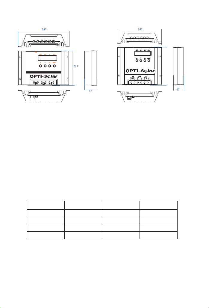
4.Dim ensions
Max-H A series
Solar ch arge co ntrol ler
Figure 1:The si ze of SC-Ma x30/ 40 Figure 2:The si ze of SC-Ma x50/ 60
164
5. Inst all ation
5.1 M oun ting l ocation r equi rements
Do not mount the solar charge controller outdoors or in wet rooms. Do not subject the solar charge controller to
direct sunshine or other sources of heat. Protect the solar charge controller from dirt and moisture. Mount upright
on the wall on a non-flammable substrate. Maintain a minimum clearance of 10cm below and around the device to
ensure unhindered air circulation. Mount the solar charge controller as close as possible to the batteries.
5.2 F ast enin g the so lar c harg e control ler
Mark the position of the solar charge controller fastening holes on the wall, drill 4 holes and insert dowels, fasten
the solar charge controller to the wall with the cable openings facing downwards.
5.3 P rep arat ion of wiri ng
Model Max. current
Diamete(mm2)
AWG
SC-30MAX 30A 16 6
SC-40MAX 40A 16 6
SC-50MAX 50A 20 4
SC-60MAX 60A 20 4
5.4 Conn ecti on
We strongly recommend connecting a fuse directly to the battery to protect any short circuit at the battery wiring.
Solar PV modules create current whenever light strikes them. The current created varies with the light intensity,
but even in the case of low levels of light, full voltage is given by the modules. So, protect the solar modules from
incident light during installation. Never touch uninsulated cable ends, use only insulated tools, and make sure that
the wire diameter is in accordance with the solar charge controller’s expected currents. Connections must always
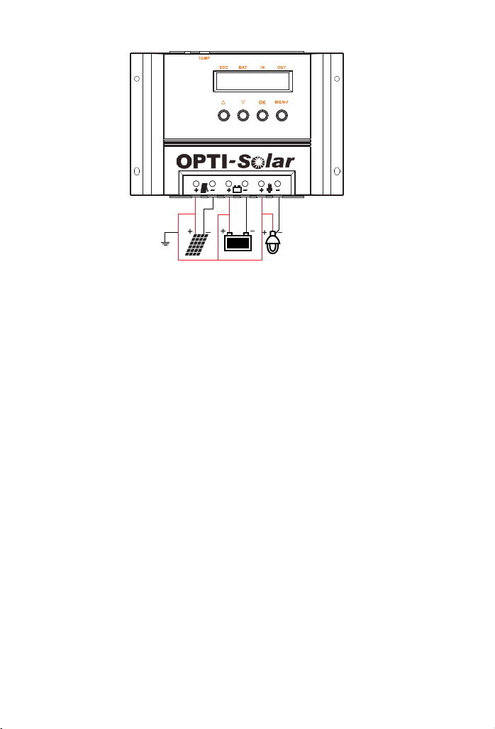
be made in the sequence described below (Figure 3: System wiring diagram).
Page2/ 13 Pag es
Page 5
⑤
⑥
③
Figure 3 : Syst em wiring
1st step: Connect the battery
Connect the battery connection cable with the correct polarity to the middle pair of terminals on the solar charge
controller (with the battery symbol). If the system is 12V, please make sure that the battery voltage is within
10V~16V, else if the system is 24V, the battery voltage should between 20V~30V. If the polarity is correct, the
LCD screen on the controller will begin to show.
2nd step: Connect the solar module
Ensure that the solar module is protected from incident light. Ensure that the solar module does not exceed the
maximum permissible input current. Connect the solar module connection cable to the correct pole of the left pair
of terminals on the solar charge controller (with the solar module symbol).
3rd step: Connect loads
Connect the load cable to the correct pole of the right pair of terminals on the solar charge controller (with the
lamp symbol). To avoid any voltage on the wires, first connect the wire to the load, then to the controller.
4th step: Final work
Fasten all cables with strain relief in the direct vicinity of the solar charge controller (clearance of approx.10cm).
5.5 Grou ndin g
Be aware that the positive terminals of the controller are connected internally and therefore have the same
electrical potential. If any grounding is required always do this on the positive wires.
!
Remark: If the device is used in a vehicle which has the battery negative on the chassis, loads
connected to the controller must not have an electric connection to the car body, otherwise the low voltage
disconnect and electronic fuse functions of the controller are short circuited.
②
①
④
Page3/ 13 Pag es
Page 6
6.Indi cati on of Statu s
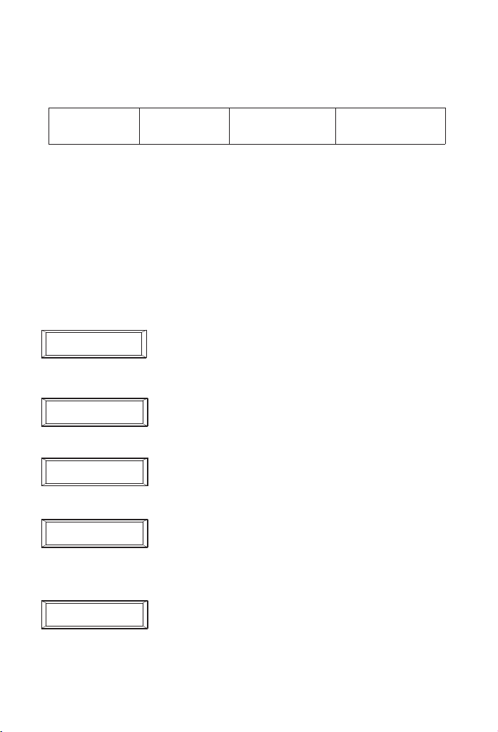
The two-line display indicates all present system values in short form on the top line, and the values are without
units (Volt, Amp, etc) due to a lack of space. The printing above each value serves as a reminder:
State of charg e
SOC
“SOC” means "state of charge" and indicates how much remaining capacity the battery still has. The SOC is
never 100% as due to technical reasons it is easier to indicate a two-digit number.
“BAT ” shows t he bat tery 's act ual vol tage .
“IN” is the sum of the charging currents flowing into the battery.
“OUT” is the sum of discharge currents flowing out of the battery.
The second line constantly changes its information. All values and system information are indicated alphanumerically. The following displays can only be seen during regular operation (not while programming).
Batter y volt age
BAT
Chargi ng cur rents
IN
Discha rge cu rrents
OUT
SOC
BAT IN
88% 1 2.7 26 1 8
I acc u = 8.3A
88% 1 2.7 26 0 0
I in = 26 .4A
88% 1 2.7 00 1 5
Temp = 25℃
88% 1 2.7 17 1 5
Boo st cha rgin g
88% 1 2.7 00 1 5
Loa d on
OUT
“I accu” is the balance of all charging and discharging currents. As long as the
charging current is higher than the discharging current, the value is position, in the
opposite case, it is negative.
“I in” shows the charging current at the moment. When the voltage of the battery is
getting near the final charge voltage, the solar charge controller will regulate the “I
in” in order to protect the battery from being overcharged. The charge current “I in”
is lower than the module current.
“Temp” displays the environment temperature of the solar charge controller.
The solar charge controller status such as "Fast charging", "Equal charging”, ”Boost
charging”, ”Float charging” and "No Charging” indicate which stage of charging is in
process. After a certain period of time of operation in the “Boost” and “Equal”
charging modes, the “Float” charge mode is resumed.
The content displays the current load state, “Load on” means the load has been
opened, “Load off” means the load is in a closed state.
Page4/ 13 Pag es
Page 7
7.Operating the solar charge controller
7.1 Factory Pre-Set configurations
With the factory pre-set configurations, the solar charge controller can be used in most applications without further
programming. On delivery, the controller is always set with these pre-set basic configurations that enable
immediate use of most typical solar systems after installation.
The solar charge controller can be reset to the factory pre-set configurations at any time with the Menu CONF.
7.2 Main Menu
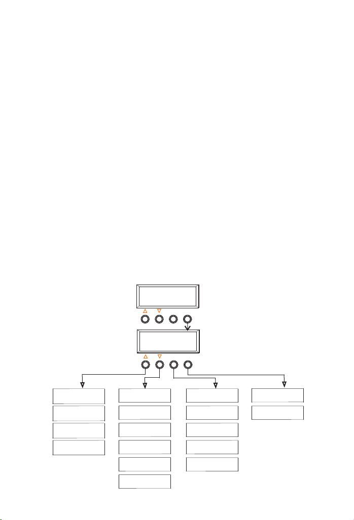
Set values and functions can be adjusted with the four control keys on the panel. By pressing the key under the
MENU, a Main Menu appears in the display – Conf (System module settings), Prog (System parameter settings),
Load (Load mode settings) and Logg (Inquiry of internal data logger). By pressing the key below the corresponding
abbreviation, you can enter the corresponding menu (Figure 4: Programming Menu).
After entering the corresponding menu, the following actions can be set or viewed the appropriate information:
①You can use the keys ▲▼ to select sub-menu, and press the OK button to enter the sub-menu.
②After entering the sub-menu, press ▲▼ to change the value.
③After setting, press the OK button to save the set value, and return to the previous menu level.
④Pressing the MENU key will exit the setting, bring the display back to the normal Main Menu.
!
Note: 1.If you did not carry out any operation within 60s after , the controller will
entering the setup menu
automatically exit the menu programming and the normal indication of running status appears . 2.If there are
no adjustments on an activated submenu value being changed, the display indication jumps to the main menu
and the adjustment in the open window is not stored or applicable.
Fig ure 4: P rogr amming Menu
Bat tery typ e
Liq uid
Nom inal cap acity
300 Ah
Reg ulatio n
SOC
Fac tory adj ust
Pre ss OK+ME NU
88% 1 2.7 26 18
I acc u = 8.3A
Con f Load
Pro g Logg
Flo at charg e
13. 7V
Boo st charg e
14. 5V
Equ al charg e
14. 8V
D/N t hresh old
3.0 V
Dis connec t
30%
Rec onnect
50%
OK
OK
MENU
MENU
Loa d contro l
AUTO
Lig ht on
00: 00
Lig ht off
00: 00
Nig ht timer 1
00: 00
Nig ht timer 2
00: 00
del ay
del ay
Day i n 100
Ah ou t 80
Total in 1 200
KAh o ut 880
Page5/ 13 Pag es
Page 8
7.3 M enu Co nf (System mo dule s etti ngs)
In this menu, you can configure the system modules, including battery type, battery nominal capacity, low voltage
protection mode and activate pre-set configurations. Press ▲ to enter the menu.
Bat tery typ e
Liq uid
Battery type selection: Press the OK button to enter the menu, you may toggle between
Gel to liquid electrolyte.
Pos sibi liti es for progra mmin g: Liq uid, G el (Def ault : Liqu id).
▲▼
Battery nominal capacity: Press the OK button to enter the menu, press arrow keys ▲▼for
Nom inal cap acity
300 Ah
Reg ulatio n
Soc
changing the nominal capacity and press OK for entering the new value.
Pos sibi liti es for progra mmin g: 10A h~99 90Ah (Defau lt: 30 0Ah) .
Note: The nominal capacity must be consistent with the actual battery capacity when the
controller is installed.
Low voltage protection mode (Soc or voltage control) settings: Press the OK button to enter
the menu, and switch with the keys ▲ ▼ between SOC and Voltage.
Pos sibi liti es for progra mmin g: Soc , Voltage (Def ault : Soc) .
Fac tory adj ust
Pre ss OK+ME NU
.4 Menu P
7
n
e
his m
n t
I
o en
t
s ▼
s
re
P
We h
:
ote
N
, ce
r
e
v
e
w
Ho
fo
r
e
m p
ste
sy
t c
e
-s
re
e p
th
Flo at charg e
13. 7V
Boo st charg e
14. 5V
Factory pre-set: Press the OK button to enter the menu, and press the
"OK + M ENU" b utton simul tane ousl y to reset the so lar ch arge c ontroller.
Note: If you press “OK+MENU”, all settings and values will be reset and the execution will
be confirmed by “Done”.
)
s
ng
ti
et
er s
met
ra
a
em p
t
s
y
g (S
o
r
, LVD and LVR data
d
l
o
h
s
hre
h t
ig
N
ay/
, D
s
r
e
et
m
a
ng par
i
g
he char
u can set t
u yo
a
r
rm
on
ve tri
in sk
a
t
fig
te
an
r t
ce. I
u
u.
n
e me
h
e th
g
t d
ama
t do no
a
s th
nge
in ra
th
d wi
e
imit
ues are l
l
e va
h
t t
a
e t
sur
h
in
d t
e
o
d to p
e
n
r
e
c
on
s c
ur i
avio
y beh
ter
t
r as ba
a
s f
d a
e
d
ee
n
re
s a
ll
i
s
g
in
t
t
ese se
h
ny of t
t a
u
o
b
sure a
un
e
r
u a
o
f y
s a
n
atio
r
.
e
y a
r
he
s t
, ple
er to yo
f
e
e r
as
g
n
t lo
n
e
v
e
r
ur au
Float voltage settings: Press the OK button to enter the menu, press ▲ ▼ to change the
value.
Note: The float voltage serves for maintaining the charge in the battery for long periods and
preventing self-discharge. This voltage should not be too high, since this may lead to
permanent gassing, which damages the battery. Maximum values are stated on the battery
data sheet of your battery. For most types of liquid battery, this float value is 13.7V/27.4V.
Possibilities for programming: 13.0~14.5V/26.0V~29.0V (Default: 13.7V/27.4V).
Boost voltage settings: Press the OK button to enter the menu, press ▲ ▼ to change the
value.
Possibilities for programming: 14.0~15.0V/28.0V~30.0V (Default: 14.5V/29.0V).
.
ely.
t
a
edi
m
ry im
e
t
e bat
am
m d
er
t
-
e
d d
e
ris
o
h
t
r
o
e o
o
ag
r p
ve
ea
r or l
e
l
a
Page6/ 13 Pag es
Page 9
Equ al charg e
14. 8V
D/N t hresh old
3.0 V
Dis connec t
Soc = 30 %
Equal voltage settings: Press the OK button to enter the menu, press ▲ ▼ to change the
value.
Note: 1.The equalisation charging can only be adjusted for batteries with liquid electrolyte,
since high equalising voltages are harmful for sealed batteries. The maximum equalising
voltage value should be stated on the battery manufacturer's data sheet.
2.This window is deactivated if you have selected “Gel” with the menu CONF.
3.Battery charging voltage is passed on directly to the loads by the solar charge controller.
Therefore, during equal charging, high charging voltages can be programmed that may
damage some loads. Please select this equal charge voltage very carefully and compare the
desired value to the battery and load (appliance) manufacturers' data sheets.
Possibilities for programming: 14.0~15.5V/28.0V~31.0V (Default: 14.8V/29.6V).
Note: The fast charge voltage is fixed at 14.0V/28.0V, users do not have their own set.
Day/Night threshold settings: Press the OK button to enter the menu, press ▲ ▼ to change
the value.
The controller recognizes day and night based on the solar array open circuit voltage (only
functional in street-light mode). This day/night threshold can be modified according to local
light conditions and the solar array used.
Possibilities for programming: 3.0~7.5V/6.0V~15.0V(Default: 3.0V/6.0V).
Low voltage disconnect settings: Press the OK button to enter the menu, press ▲ ▼ to
change the value.
Note: 1.The difference between disconnect and reconnect threshold must be at least 20%.
If you wish disconnect at higher state of charge you have to first adjust the reconnect
threshold (as per below) to 20 % above the desired disconnect threshold.
2.When you configure voltage regulation, you will find in this window voltage values instead
of SOC values for programming the disconnection voltage level.
The solar charge controller allows the smallest difference between reconnect and disconnect
is 0.8V/1.6V. If you want to program a high level for disconnection you must first increase
the reconnection level.
Possibilities for programming by SOC: 20%~70% (Default: 30%).
Possibilities for programming by voltage regulation:
11.0~12.5V/22.0~25.0V (Default: 11.1V/22.2V).
Rec onnect
Soc = 50 %
Low voltage reconnected settings: Press the OK button to enter the menu, press ▲ ▼ to
change the value.
Possibilities for programming by SOC: 40%~90% (Default: 50%).
Possibilities for programming: by voltage regulation:
11.8V/23.6V~13.3V/26.6V (Default: 12.6V/25.2V).
Page7/ 13 Pag es
Page 10
7.5 M enu Lo ad (Load mode s etti ngs)
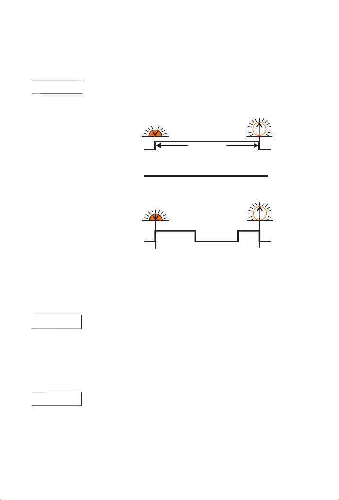
We can set load mode and time in this menu (Figure 5: Load mode), press the OK button to enter this menu.
Loa d contro l
AUTO
Load mode settings: Press the OK button to enter the menu, and press ▲ ▼ to change the
load mode.
Possibilities for programming: “Auto”, “Standard”, “Timer” (Default: Auto).
Aut o: Dus k to dawn mode
Sta ndar d: Loa d on mode
Time r: Dou ble ti me mod e
The time delay of load open settings: Press the OK button to enter the menu, press ▲ ▼ to
change the value.
Lig ht on
del ay
00: 00
The solar charge controller can control night lighting automatically by evaluating the density
of outside light with the help of the solar PV module array. Depending on the PV array
alignment or shading, it may well be that night recognition is activated even though twilight
has not yet come to an end. By the programmable time adjustment "Light on delay”, the
night light switch-on may be shifted to a later time.
Possibilities for programming: 00:00~02:00 (Interval 5min, Default: 00:00)
Day/Ni ght th reshold
Sunset Sunris e
Light on
Light off
Dusk to da wn
Day/Ni ght th reshold
Day/Ni ght th resholdDay/Ni ght th reshold
Sunset
Light on
Nig ht time r1
Light on
Nig ht time r2
Light off
Fig ure5 : Load m ode
Light off
Sunris e
Light offLight off
Lig ht off
del ay
00: 00
Note: When the controller is set to "Standard", "Light on delay" and "Light off delay" have no effect on it, but
when the controller is set to "Auto" and "Timer", the delay time settings work.
The delay time of load close settings: Press the OK button to enter the menu, press ▲ ▼
to change the value.
After setting "Light off delay" the light can remain on a period of time after dawn.
Possibilities for programming: 00:00~02:00 (Interval 5min, Default: 00:00).
Page8/ 13 Pag es
Page 11
Nig ht timer 1
00: 00
Nig ht timer 2
00: 00
Night time 1 settings: Press the OK button to enter the menu, press ▲ ▼ to change the
value.
When the “Load control" is set to "Timer", "Night timer 1” is the first part light on time when
dusk coming. If set to "Auto" or "Standard", "Night timer 1" setting is invalid.
Pos sibi liti es for progra mmin g: 00: 00~0 9:00 (Inter val 15 min, Defa ult: 0 0:00).
Night time 2 settings: Press the OK button to enter the menu, press ▲ ▼ to change the
value.
When the “Load control" is set to "Timer", "Night timer 2” is the second part light on time
before dawn. If set to "Auto" or "Standard", "Night timer 2" setting is invalid.
Pos sibi liti es for progra mmin g: 00: 00~0 9:00 (Inter val 15 min, Defa ult: 0 0:00).
7.6 M enu Lo gg ( )
Press MENU button to enter the menu, you can recall stored data values from today to the last 7 days, at the
same time you can view the accumulated value in and out of the system since the controller installed.
Day i n 100
Ah ou t 80
Inq uiry o f inte rnal da ta log ger
From this menu window, you can read the actual daily value of amp-hours in and out of the
system. Press OK to toggle the display from today’s current running data values to the
stored data values for the last 7 days. You can choose the desired day to view with the
arrow key ▲▼. The values can not be changed.
Note: "Day" simply stands for today and “Day 1”for the day before, “Day 2” means two
Day 1 i n 120
Ah ou t 90
Total in 1 200
KAh o ut 880
days ago. When a new day of logging starts, the data for each of "Day” to “Day 6” will be
shifted to the previous day, i.e. the 7th day data will be replaced with the data for the 6th
day, 6th day replaced by 5th day, etc.
View the accumulated value in and out of the system since the controller installed, this
data can not be changed.
Note: The minimum value is 1KAh.
Note: All historical data will be deleted only when the device been reset to factory settings.
Page9/ 13 Pag es
Page 12
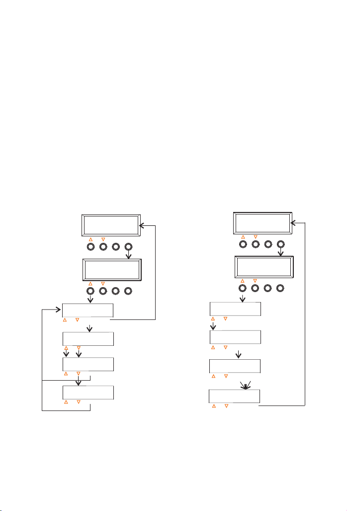
7.7 Example of configuration
7.7.1 Battery type
By pressing the MENU key, you leave the online status display and go to the main menu. By pressing the key
below the corresponding abbreviation: Conf (System module settings), Prog (System parameter settings) , Load
(Load mode settings) and Logg (Inquiry of internal data logger), you can enter the corresponding menu. In the
case of this example you have to press the first key from left (labelled▲), which is below the abbreviation Conf.
This is how you get into the window for programming the Battery type (Figure 6: Change the battery type).
Note: If you have pressed the wrong key by accident, press MENU to get back to the main menu and
start all over again.
7.7.2 Reset to Factory Pre-Set Configuration
In the previous section, it is described how to enter the window Battery type. The next window up (press ▲) is for
resetting the solar charge controller to the factory pre-set configuration (Factory adjust). By pressing OK you can
enter the Factory adjust window. The instruction to press the MENU key plus the OK key appears immediately.
Only by pressing both of these keys simultaneously will the factory pre-set configurations be set. Then the second
line shows "Done", means successfully restore the factory settings (Figure 7: Reset to Factory Pre-Set
configuration).
88% 1 2.7 26 18
I acc u = 8.3A
MENU
OK
Con f Load
Pro g Logg
MENU
OK
Bat tery typ e
Bat tery typ e
Liq uid
Bat tery typ e
Gel
Bat tery typ e
Liq uid
MENU
OK
MENU
OK
MENU
OK
MENU
OK
Fig ure 6: C hang e the bat tery t ype
Figure 7: Reset to Factory Pre-Set configuration
88% 1 2.7 26 18
I acc u = 8.3A
Con f Load
Pro g Logg
Bat tery typ e
OK
Fac tory adj ust
OK
Fac tory adj ust
Pre ss OK+ME NU
OK
Fac tory adj ust
Don e
OK
MENU
MENU
MENU
MENU
MENU
OK
MENU
OK
Note: 1. If you want to make sure that you have programmed correctly, press only OK and move through all
submenu items to check the values. Do not press the arrow keys while checking, or you will change the values.
2. If you have programmed a wrong value, you will reach the window with the undesired value again and press
OK to change the value to the correct one by pressing the arrow keys▲▼.
Page10 /13 Pa ges
Page 13
8 Safety Measures
We urgently recommend the installation of a safety device on the battery pole in order to prevent damage from
short circuits between battery and the solar charge controller.
8.1 Electronic Short Circuit Safety
An electronic short circuit safety device is built into the solar charge controller and prevents both destruction of
the solar charge controller and the blowing of the safety fuse in case of short circuits on the load terminals. The
second line of the LCD display indicates this error as "Short circuit". After elimination of this fault, the solar charge
controller automatically switches back to normal operation after about 60 seconds.
8.2 Hardware Safety
In addition to the electronic fuse device mentioned above, the solar charge controller has also been protected
by regular fuses which have been rated far beyond nominal currents to prevent false blowing of the fuses during
surges. The safety fuses are wired in parallel. In order to prevent fuses from blowing in the case of high currents
over a short period of time, a high value has been selected. Before the fuses blow, the electronic safety fuse
should prevent any excessive current flow.
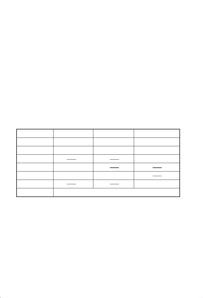
8.3 Safe ty Fea ture s
Solar termi nal
Reverse pol arity
Short circu it
Over curren t
Reverse Cur rent
Over voltag e
Low voltage
Over temp
*1 Controller can not protect itself in a 24V system when polarity of battery or solar is reversed.
*2 Controller can protect itself, but loads might be damaged.
*3 Battery must be protected by fuse, or battery will be permanently damaged.
*4 The solar panel voltage should not exceed this limit for a long time as voltage protection is done by a
varistor.
Warning: The combination of different error conditions may cause damage to the controller.
Always remove the error before you continue connecting the controller.
Protect ed *1
Protect ed
Protect ed
Max. 55V *4
switche s off the load if the temperature reaches the set value
Page11/13 Pag es
Battery ter minal
Protect ed *1
Protect ed *3
Max. 40V
Load termin al
Protect ed *2
Switche s off immedia tely
Switche s off with delay
Switche s off
Page 14

9 Mal functio ns and Erro rs
The solar charge controller is protected against damage by various measures. Nevertheless, always take utmost
care in the proper operation of the solar charge controller. Short hints of the malfunctions are indicated with the
help of the LCD display. However, errors are only properly indicated in which the system has been properly
installed. If there are other malfunctions than the ones described below, please check first of all if the solar charge
controller has been connected to the battery, the module and the loads correctly in the right polarity. Afterwards,
check the safety fuses.
Err or mess age
Sho rt circ uit
Ove r curre nt
Low v oltag e
Ove r heat
Ove r volta ge
LCD h as no
dis play
The c aus e of the m alfu nct ion
Sho rt circ uit
The load current is too high and the
output is disconnected. Either the whole
consumption exceeds the max. discharge
currents or the max. Pulse currents were
exceeded by using high surge appliances.
Battery has low capacity. To protect the
battery, all loads powered by the solar
charge controller will be disconnected.
The maximum allowable temperature has
been exceeded. In order to reduce further
heat generation the loads are disconnected
automatically. As soon as the solar charge
controller has cooled down, normal
operation will resume.
In particular, the recharge process through
back-up generators or chargers tied directly
to the battery causes battery voltages
higher than 16.5V/33.0V.
• There is no voltage feed from the battery.
• current operating temperature is too high
or too low above/below the operating
temperature, causing LCD not to function.
Rem edy
Switch off all loads. Remove the fault,
the controller will switch on load
automatically after 1 minute.
• Reduce loads or hours of operation of loads
to keep the battery from being discharged
deeply, or increase solar array to add
energy to the system.
• Connect all loads through the controller to
avoid strong discharge of the battery.
• It will restore only when the battery being
recharged and the voltage reaching the
reconnect voltage.
• Check the ventilation at the back heat
sink and clean it if necessary.
• Protect the controller from direct sunshine.
• Reduce warming caused by appliances
near the controller.
• Reduce the loads or PV modules.
Dis conne ct exte rnal ch arger s, when t he
bat tery vo ltage i s lower t han 15. 5V/31 .0V
controller automatically restored.
• Check the battery connections and fuses.
• Check the working temperature.
• Reinstall the controller, disconnect
everything and connect it again in the
right order.
Page12 /13 Pa ges
Page 15
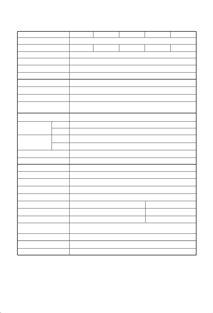
10. Techn ical Data
Mod e
Sys tem vol tage
Max s olar or l oad cur rent
Fas t volta ge
Boo st volt age
Equ al volt age
Flo at volt age
Day /Nigh t thres hold
Nom inal ca pacit y
Bat tery ty pe
Tempe ratur e compe nsati on
LVD pr otec tion m ode
Loa d disco nnect
vol tage
Loa d recon nect
vol tage
Loa d mode
Lig ht on del ay
Lig ht off de lay
Nig ht time 1
Nig ht time 2
Max s olar vo ltage
Max b atter y volta ge
Dim ensio ns/We iht
Max w ire siz e
Max p ower co nsump tion
Tempe ratur e Range
dur ing ope ratio n
Sto rage te mpera ture
Soc
Volt age
Soc
Volt age
Relati ve hum idity
Cas e prote ction
M a x 2 0 M a x 3 0 M a x 4 0
12V /24V au tomat ic reco gniti on
4 0 A3 0 A2 0 A
14. 0V/28 .0V(2 5℃)
14. 0~15. 0V/28 .0~30 .0V( def ault : 4 .Pro gramm able) , 1 5V/ 29.0V (25℃)
14. 0~15. 5V/28 .0~31 .0V( def ault : 4 . (25℃)Pro gramm able) , 1 8V/ 29.6V
13. 0~14. 5V/26 .0~29 .0V( def ault : 13 .7V/2 7.4VPro gramm able) , (25℃)
3.0 ~7.5V /6.0~ 15.0V ( def ault : 3. 0V/6. 0VPro gramm able) ,
10A h~999 0Ah( def ault : Pro gramm able) , 300 Ah
Liq uid, Ge l( defa ult : Liq uid)
-4. 17 mV/K p er cell ( Boost a nd Equa l charg e),
-3. 33 mV/K p er cell ( Float c harge )
Soc , Voltag e(def ault : So c)
20~ 70%( def ault : 30 %Pro gramm able) ,
11.0 ~12. 5V/2 2.0~ 25.0 V( d efau lt : Prog ramm able ), 11 .1V/ 22.2 V
40~ 90%( def ault : 50 %Pro gramm able) ,
11.8 ~13. 3V/2 3.6~ 26.6 V(Pr ogra mabl e), de faul t : 12.6 V/25 .2V
Aut o, Stan dard, Ti mer(d efaul t : Aut o)
00: 00~02 :00(I nterv al 5min , Progr ammab le), de fault : 0 0:00
00: 00~02 :00(I nterv al 5min , Progr ammab le), de fault : 0 0:00
00: 00~09 :00(I nterv al 15mi n, Prog ramma ble), d efaul t : 00:00
00: 00~09 :00(I nterv al 15mi n, Prog ramma ble), d efaul t : 00:00
55 V
40 V
127 *189* 47 / 550g
25m m²
13. 8mA
-10℃ ~ + 60 ℃
-25℃ ~ + 80 ℃
M a x 5 0
5 0 A
164 *189* 47 / 690g
50mm²
15m A
M a x 6 0
6 0 A
10%~90 % Non- condens atio n
IP3 2
Page13 /13 Pa ges
 Loading...