

opti-solar SC-Max, SC-50MAX, SC-30MAX, SC-40MAX, SC-60MAX User Manual

SC-Max series
Solar Charge Controller
30A/40A/50A/60A
User Manual

Contents
1 Description of function
2 Safety Instructions and Waiver of Liability
2.1 Safety
2.2 Liability Exclusion
3 Optional
3.1 Remote display unit
3.2 Remo te tem peratur e sens or
Dimens ions
4
5 Instal lati on
5.1 Moun ting l ocation r equi rements
5.2 Fast enin g the solar c harg e control ler
5.3 Prep arat ion of wiri ng
5.4 Conn ecti on
5.5 Grou ndin g
6 Indica tion o f Status
7 Ope rat ing th e solar cha rge co ntrolle r
7.1 F acto ry Pre -Set co nfig urat ions
7.2 Main M enu
7.3 Menu Conf (System module settings)
7.4 Menu Prog (System parameter settings)
7.5 Menu Load (Load mode settings)
7.6 Menu Logg (Inquiry of internal data logger)
7.7 Example of configuration
7.7 .1 Bat tery t ype
7.7 .2 Res et to Factory P re-S et Con figu ration
8 Safety Measures
8.1 E lect roni c Short Circu it Saf ety
8.2 H ardw are Sa fety
8.3 S afet y Feat ures
9 Malfunctions and Errors
10 Technical Data
P 1
P 1
P 1
P 1
P 1
P 1
P 1
P 2
P 2
P 2
P 2
P 2
P 2
P 3
P 3
P 4
P 5
P 5
P 5
P 6
P 6
P 8
P 9
P 10
P 10
P 10
P 11
P 11
P 11
P 11
P 12
P 13

Dear Clients,
Thanks for selecting the SC- Max series solar controller. Please take the time to read this user manual, this will
help you to make full use of many advantages the controller can provide your solar system.
This manual gives important recommendations for installing, program, using and so on. Read it carefully in your
own interest please.
1. Description of function
With your new Max controller you own a state-of-the
art device which was developed according to the latest
available technical standards. It comes with a number
of outstanding features, such as:
LCD display
One year's data memory
12V/24V automatic recognition
External temperature sensor, make the temperature
compensation more accurate
Perfect EMC design
Many choices of battery type, working mode and
protection
Four stage PWM charge way: fast, boost, equalization,
float
Full automatic electronic protect function
3. Optional
3.1 Remote display unit
Remote display unit can display system information,
failure information and one year's charge and discharge
data.
3.2 Remote temperature sensor
Acquisition the ambient temperature of the battery, which
can be accurate compensation charge values, standard
wire length is 2 meters (can also be customized according
to user needs).
2.Saf ety instr uctions and wa iver
of liab ility
2.1 Safety
①The solar charge controller may only be used in
PV systems in accordance with this user manual
and the specifications of other modules
manufacturers. No energy source other than a solar
generator may be connected to the solar charge
controller.
②Batteries store a large amount of energy, never
short circuit a battery under all circumstances.
We strongly recommend connecting a fuse
directly to the battery to protect any short circuit
at the battery wiring.
③Batteries can produce flammable gases. Avoid
making sparks, using fire or any naked flame.
Make sure that the battery room is ventilated.
④Avoid touching or short circuiting wires or
terminals. Be aware that the voltages on special
terminals or wires can be as much as twice the
battery voltage. Use isolated tools, stand on dry
ground, and keep your hands dry.
⑤Keep children away from batteries and the
charge controller.
Liabil ity Ex clusion
2.2
The m anu fact urer shal l not be l iable for
damage s, esp ecially o n the ba ttery, caused
by use oth er tha n as intend ed or as m entione d
in th is ma nual o r if the reco mmen dations o f
the b att ery ma nufa ctu rer ar e neglect ed. Th e
manufa ctur er shall no t be lia ble if ther e has
been ser vice o r repair ca rrie d out by any
unauth oriz ed person , unus ual use, wr ong
instal lati on, or bad sy stem d esign.
Page1/ 13 Pag es
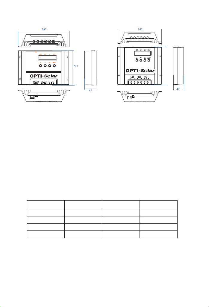
4.Dim ensions
Max-H A series
Solar ch arge co ntrol ler
Figure 1:The si ze of SC-Ma x30/ 40 Figure 2:The si ze of SC-Ma x50/ 60
164
5. Inst all ation
5.1 M oun ting l ocation r equi rements
Do not mount the solar charge controller outdoors or in wet rooms. Do not subject the solar charge controller to
direct sunshine or other sources of heat. Protect the solar charge controller from dirt and moisture. Mount upright
on the wall on a non-flammable substrate. Maintain a minimum clearance of 10cm below and around the device to
ensure unhindered air circulation. Mount the solar charge controller as close as possible to the batteries.
5.2 F ast enin g the so lar c harg e control ler
Mark the position of the solar charge controller fastening holes on the wall, drill 4 holes and insert dowels, fasten
the solar charge controller to the wall with the cable openings facing downwards.
5.3 P rep arat ion of wiri ng
Model Max. current
Diamete(mm2)
AWG
SC-30MAX 30A 16 6
SC-40MAX 40A 16 6
SC-50MAX 50A 20 4
SC-60MAX 60A 20 4
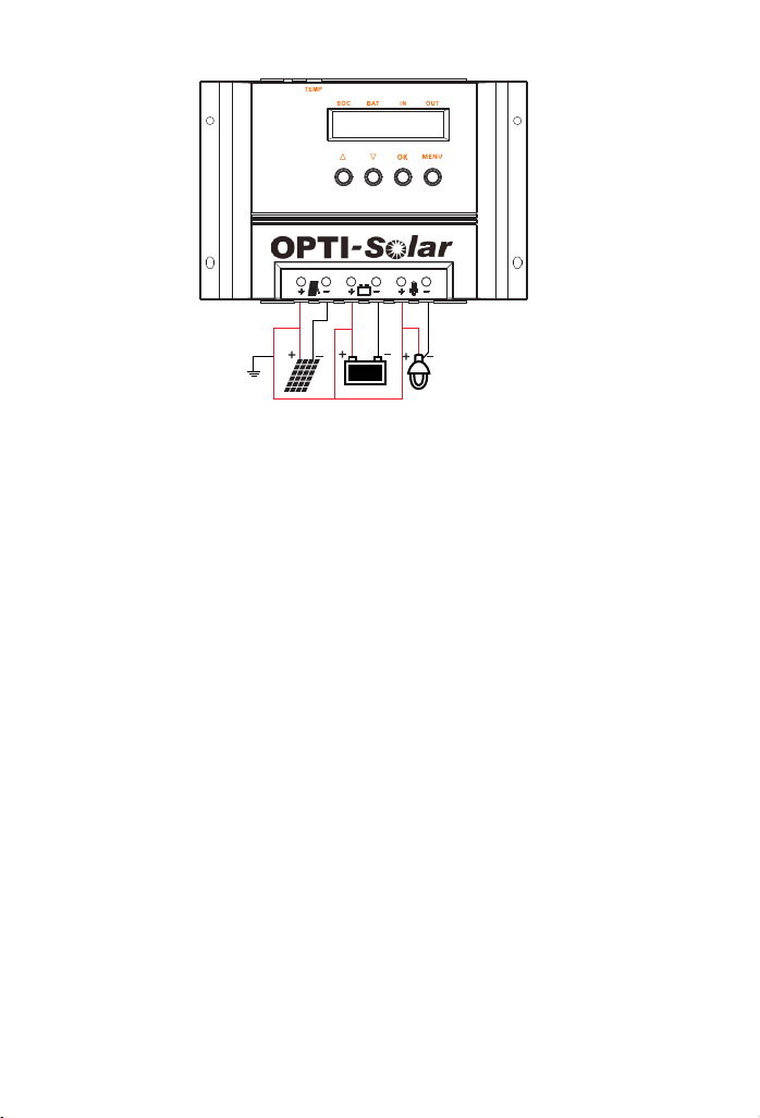
5.4 Conn ecti on
We strongly recommend connecting a fuse directly to the battery to protect any short circuit at the battery wiring.
Solar PV modules create current whenever light strikes them. The current created varies with the light intensity,
but even in the case of low levels of light, full voltage is given by the modules. So, protect the solar modules from
incident light during installation. Never touch uninsulated cable ends, use only insulated tools, and make sure that
the wire diameter is in accordance with the solar charge controller’s expected currents. Connections must always
be made in the sequence described below (Figure 3: System wiring diagram).
Page2/ 13 Pag es
⑤
⑥
③
Figure 3 : Syst em wiring
1st step: Connect the battery
Connect the battery connection cable with the correct polarity to the middle pair of terminals on the solar charge
controller (with the battery symbol). If the system is 12V, please make sure that the battery voltage is within
10V~16V, else if the system is 24V, the battery voltage should between 20V~30V. If the polarity is correct, the
LCD screen on the controller will begin to show.
2nd step: Connect the solar module
Ensure that the solar module is protected from incident light. Ensure that the solar module does not exceed the
maximum permissible input current. Connect the solar module connection cable to the correct pole of the left pair
of terminals on the solar charge controller (with the solar module symbol).
3rd step: Connect loads
Connect the load cable to the correct pole of the right pair of terminals on the solar charge controller (with the
lamp symbol). To avoid any voltage on the wires, first connect the wire to the load, then to the controller.
4th step: Final work
Fasten all cables with strain relief in the direct vicinity of the solar charge controller (clearance of approx.10cm).
5.5 Grou ndin g
Be aware that the positive terminals of the controller are connected internally and therefore have the same
electrical potential. If any grounding is required always do this on the positive wires.
!
Remark: If the device is used in a vehicle which has the battery negative on the chassis, loads
connected to the controller must not have an electric connection to the car body, otherwise the low voltage
disconnect and electronic fuse functions of the controller are short circuited.
②
①
④
Page3/ 13 Pag es
 Loading...