

opti-solar SC MPPT, SC-20MPPT, SC-40MPPT User Manual

Solar Charger Controller
SC-20/40 MPPT
Version: 1.1
User Manual

Table Of Contents
1.Safety instrucitons and waiver of liability ................................................................................................... 1
1.1 Safety Instructions ..................................................................................................................................... 1
1.2 Liability Exclusion ...................................................................................................................................... 1
2. Pruduct Overview .......................................................................................................................................... 2
2.1 Outstandong Features
2.2 MPPT ......................................................................................................................................................... 2
2.3 Four Charging Stage ....................................................................................................... .......................... 4
3. Dimensions .................................................................................................................................................... 5
3.1 The dimensions of SC-20MPPT ................................................................................................................ 5
3.2 The dimensions of SC-40MPPT ................................................................................................................ 6
4. Structure & Accessory .................................................................................................................................. 7
4.1 Structure & Characteristics of SC-20MPPT .............................................................................................. 7
4.2 Structure & Characteristics of SC-40MPPT .............................................................................................. 8
4.3 Optional Accessories ................................................................................................................................. 8
5. Installation ..................................................................................................................................................... 9
5.1 Installation Notes ....................................................................................................................................... 9
5.2 Mounting Location Requirements.............................................................................................................. 9
5.3 Wiring Specifications………………………………………………………………………………………...10
5.4 Connection……………………………………………………………………………………………………10
5.5 Grounding
6.Operarion ...................................................................................................................................................... 12
6.1.1 Status Description
6.1.2 The interface automatically cycles ....................................................................................................... 13
6.1.3 Press OK to browse the interface
6.1.4 Fault indication………………………………………………………………………………………….….14
6.2 Key function
6.3 USB interface
6.4 Parameters setting…………………………………………………………………………………….………15
6.4.1 Low voltage protection and reconnect
6.4.2 Battery type
6.4.3 Load mode
7. Protections, Troubleshooting and Maintenance ...................................................................................... 16
7.1 Protection
7.2 Troubleshooting……………………………………………………………………………………….……...17
7.3 Maintenance
8. Technical Data ............................................................................................................................................. 18
8.1 Technical data of SC-20MPPT…………………………………………………………………..…………...18
8.2 Technical data of SC-40MPPT…………………………………………………………………..…………...19

1
Dear Clients,
Thanks for selecting OPTI-Solar SC MPPT series charger controller.
Please take the time to read this user manual, this will help you to make full use of many advantages the
controller can provide your solar system.
This manual gives important recommendations for installing and using and so on. Read it carefully in your own interest
and pay attention to the safety recommendations in it please.
1. Safety instructions and waiver of liability
1.1 Safety Instructions
The following symbols are used throughout this manual to indicate potentially dangerous conditions or mark important
safety instructions. Please take care when meeting these symbols.
WARNING: Indicates a potentially dangerous condition. Use extreme caution when performing this task.
CAUTION: Indicates a critical procedure for safe and proper operation of the controller.
CAUTION:
1. There are no user serviceable parts inside the controller. Do not disassemble or attempt to repair the
controller.
2. Keep children away from batteries and the charge controller.
1.2LiabilityExclusion
The manufacturer shall not be liable for damages, especially on the battery, caused by use other than as intended or as
mentioned in this manual or if the recommendations of the battery manufacturer are neglected. The manufacturer shall not
be liable if there has been service or repair carried out by any unauthorized person, unusual use, wrong installation, or bad
system design.

2
Magic series solar controller is based on an advanced maximum power point tracking (MPPT) technology developed,
dedicated to the solar system, the controller conversion efficiency up to 97%.
2.1 It comes with a number of outstanding features, such as:
Innovative Max Power Point Tracking(MPPT) technology, tracking efficiency >99.9%
Full digital technology, high charge conversion efficiency up to 98%
LCD display design, read operating data and working condition easily.
Real-time energy statistics function.
12/24/48V automatic recognition
AGM, Liquid and GEL battery for selection
External temperature sensor, automatic temperature compensation
Built-in temperature sensor, when the temperature exceeds the set value, the charging current will lower down
followed by the decrease of temperature, so as to control the controller’ s temperature rise
Four stages charge way: MPPT, boost, equalization, float
With current-limiting charging mode, when the power of solar panel is over-sized and charging current exceeds the
rated current, the controller will lower the charging power, which enables the system to work under the rated charging
current
Multiple load control modes: Standard, Dusk to Dawn, Timer and User-defined mode.
Two USB interfaces(EU Series)
Based RS-485 standard Modbus protocol, to maximize their communication needs of different occasions.
Perfect EMC & thermal design
Full automatic electronic protect function
MPPT profile
The full name of the MPPT is maximum power point tracking. It is an advanced charging way which could detect the
real-time power of the solar Module! and the maximum point of the I-V curve that make the highest battery charging
efficiency.
Current Boost
Under most conditions, MPPT technology will "boost" the solar charge current.
MPPT Charging: Power Into the controller (Pmax)=Power out of the controller (Pout)
lin x Vmp= lout x Vout
* Assuming 100% efficiency. Actually, the losses in wiring and conversion exist.
If the solar module's maximum power voltage (Vmp) is greater than the battery voltage, it follows that the battery current
must be proportionally greater than the solar input current so that input and output power are balanced. The greater the
difference between the Vmp and battery voltage, the greater the current boost. Current boost can be substantial in systems
where the solar array is of a higher nominal voltage than the battery as described in the next section.
3
High Voltage Strings and Grid-Tie Modules
Another benefit of MPPT technology is the ability to charge batteries with solar arrays of higher nominal voltages. For
example, a 12 Volt battery bank may be charged with a 12-, 24-, 36-, or 48-Volt nominal off-grid solar array. Grid-tie solar
modules may also be used as long as the solar array open circuit voltage (Voc) rating will not exceed the maximum input
voltage rating at worst-case (coldest) module temperature. The solar module documentation should provide Voc vs.
temperature data.
Higher solar input voltage results in lower solar input current for a given input power. High voltage solar input strings
allow for smaller gauge solar wiring. This is especially helpful and economical for systems with long wiring runs between
the controller and the solar array.
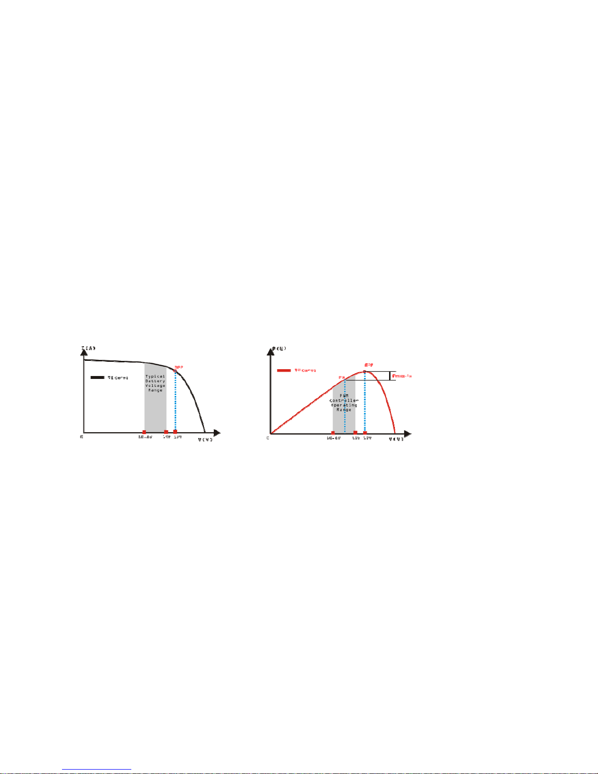
An Advantage Over Traditional Controllers
Traditional controllers connect the solar module directly to the battery when recharging. This requires that the solar
module operate in a voltage range that is usually below the module's Vmp. In a 12 Volt system for example, the battery
voltage may range from 10.8-15 Vdc, but the module's Vmp is typically around 16 or 17V.
Because traditional controllers do not always operate at the Vmp of the solar array, energy is wasted that could otherwise
be used to charge the battery and power system loads. The greater the difference between battery voltage and the Vmp of
the module, the more energy is wasted.
Nominal 12 Volt Solar Module I-V curve and output power graph
Contrast with the traditional PWM controller, MPPT controller could play a maximum power of the solar panel so that a
larger charging current could be supplied. Generally speaking, the MPPT controller's energy utilization efficiency is
15%~20% higher than PWM controller.
Conditions That Limit the Effectiveness of MPPT
The Vmp of a solar module decreases as the temperature of the module increases. In very hot weather, the Vmp may be
close or even less than battery voltage. In this situation, there will be very little or no MPPT gain compared to traditional
controllers. However, systems with modules of higher nominal voltage than the battery bank will always have an array
Vmp greater than battery voltage. Additionally, the savings in wiring due to reduced solar current make MPPT worthwhile
even in hot climates.
4
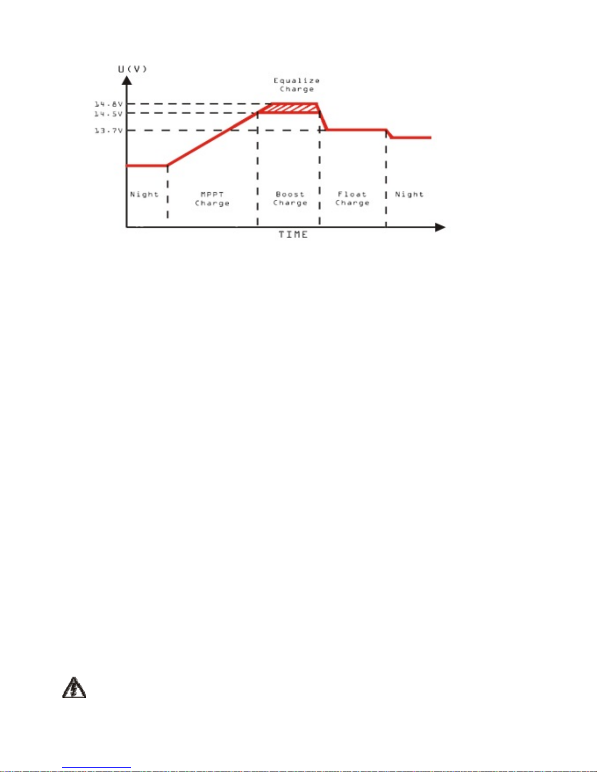
2.3 MPPT—Four Charging Stage
Magic series controller has a 4-stage battery charging algorithm for rapid, efficient, and safe battery charging.
MPPT Charge
In this stage, the battery voltage has not yet reached boost voltage and 100% of available solar power is used to recharge
the battery.
Boost Charge
When the battery has recharged to the Boost voltage setpoint, constant-voltage regulation is used to prevent heating and
excessive battery gassing. The Boost stage remains 120 minutes and then goes to Float Charge. Every time when the
controller is powered on, if it detects neither over discharged nor overvoltage, the charging will enter into boost charging
stage.
Float Charge
After the Boost voltage stage, the controller will reduce the battery voltage to Float voltage setpoint. When the battery is
fully recharged, there will be no more chemical reactions and all the charge current transmits into heat and gas at this time.
Then the controller reduces the voltage to the floating stage, charging with a smaller voltage and current. It will reduce the
temperature of battery and prevent the gassing, also charging the battery slightly at the same time. The purpose of Float
stage is to offset the power consumption caused by self consumption and small loads in the whole system, while
maintaining full battery storage capacity.
In Float stage, loads can continue to draw power from the battery. In the event that the system load(s) exceed the solar
charge current, the controller will no longer be able to maintain the battery at the Float setpoint. Should the battery
voltage remains below the boost reconnect charging voltage, the controller will exit Float stage and return to Bulk
charging.
Equalize Charge
Certain types of batteries benefit from periodic equalizing charge, which can stir the electrolyte, balance battery voltage
and complete chemical reaction. Equalizing charge increases the battery voltage, higher than the standard complement
voltage, which gasifies the battery electrolyte. If it detects that the battery is being over discharged, the solar controller
will automatically turn the battery to equalization charging stage, and the equalization charging will be 120mins.
Equalizing charge and boost charge are not carried out constantly in a full charge process to avoid too much gas
precipitation or overheating of battery.
WARNING: Risk of explosion!
Equalizing flooded battery can produce explosive gases, so well ventilation of
battery box is necessary .
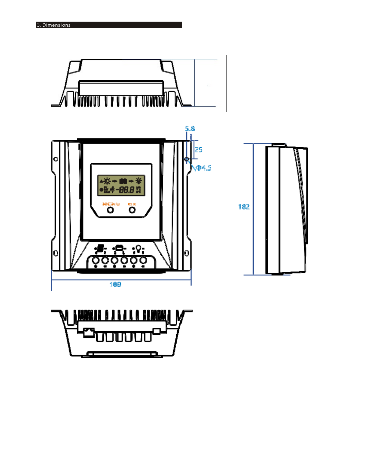
5
3.1 The dimensions of SC-20MPPT
64
 Loading...