

opti-solar 1KVA, 2KVA, 3KVA User Manual

1KVA/ 2KVA/ 3KVA
INVERTER / CHARGER
User Manual
www.opti-solar.com

CONTENTS
ABOUT THIS MANUAL ..................................................................................................................................... 1
Purpose ............................................................................................................................................................ 1
Scope ............................................................................................................................................................... 1
SAFETY INSTRUCTIONS .................................................................................................................................. 1
INTRODUCTION ............................................................................................................................................... 2
Features ........................................................................................................................................................... 2
Basic System Architecture ............................................................................................................................... 3
Product Overview ............................................................................................................................................. 4
INSTALLATION ............................................................................................................................................... 10
Unpacking and Inspection.............................................................................................................................. 10
Preparation .................................................................................................................................................... 10
Mounting the Unit ........................................................................................................................................... 11
Battery Connection ........................................................................................................................................ 12
AC Input/Output Connection .......................................................................................................................... 13
PV Connection (Only apply for the model with solar charger) ....................................................................... 15
Final Assembly ............................................................................................................................................... 16
OPERATION ..................................................................................................................................................... 17
Power ON/OFF .............................................................................................................................................. 17
Operation and Display Panel ......................................................................................................................... 17
LCD Display Icons ......................................................................................................................................... 18
LCD Setting .................................................................................................................................................... 20
Display Setting ............................................................................................................................................... 21
Operating Mode Description .......................................................................................................................... 23
Fault Reference Code .................................................................................................................................... 24
Warning Indicator ........................................................................................................................................... 24
SPECIFICATIONS ........................................................................................................................................... 25
Table 1 Line Mode Specifications ................................................................................................................... 25
Table 2 Invert Mode Specif ications ................................................................................................................ 26
Table 3 Charge Mode Specifications .............................................................................................................. 27
Table 4 General Specif ications ....................................................................................................................... 27
Charging Controls ........................................................................................................................................... 27
TROUBLE SHOOTING ..................................................................................................................................... 28
Appendix: Approximate Back-up Time Table ........................................................................................... 29

1
ABOUT THIS MANUAL
Purpose
This manual describes the assembly, installation, operation and troubleshooting of this unit. Please read
this manual carefully before installations and operations. Keep this manual for future reference.
Scope
This manual provides safety and installation guidelines as well as information on tools and wiring.
SAFETY INSTRUCTIONS
WARNING: This chapter contains important safety and operating instructions. Read and
keep this manual for future reference.
1. Before using the unit, read all instructions and cautionary markings on the unit, the batteries and all
appropriate sections of this manual.
2. CAUTION --To reduce risk of injury, charge only deep-cycle lead acid type rechargeable batteries.
Other types of batteries may burst, causing personal injury and damage.
3. Do not disassemble the unit. Take it to a qualified service center when service or repair is required.
Incorrect re-assembly may result in a risk of electric shock or fire.
4. To reduce risk of electric shock, disconnect all wirings before attempting any maintenance or cleaning.
Turning off the unit will not reduce this risk.
5. CAUTION – Only qualified personnel can install this device with battery.
6. NEVER charge a frozen battery.
7. For optimum operation of this inverter/charger, please follow required spec to select appropriate cable
size. It’s very important to correctly operate this inverter/charger.
8. Be very cautious when working with metal tools on or around batteries. A potential risk exists to drop
a tool to spark or short circuit batteries or other electrical parts and could cause an explosion.
9. Please strictly follow installation procedure when you want to disconnect AC or DC terminals. Please
refer to INSTALLATION section of this manual for the details.
10. Fuses (40A, 32VDC *4pcs for 1KVA/2KVA and *6pcs for 3KVA) are provided as over-current protection
for the battery supply.
11. GROUNDING INSTRUCTIONS -This inverter/charger should be connected to a permanent grounded
wiring system. Be sure to comply with local requirements and regulation to install this inverter.
12. NEVER cause AC output and DC input short circuited. Do NOT connect to the mains when DC input
short circuits.
13. Warning!! Only qualified service persons are able to service this device. If errors still persist after
following troubleshooting table, please send this inverter/charger back to local dealer or service center
for maintenance.

2
INTRODUCTION
This is a multi-function inverter/charger, combining functions of inverter, solar charger and battery charger to
offer uninterruptible power support with portable size. Its comprehensive LCD display offers user-configurable
and easy-accessible button operation such as battery charging current, AC/solar charger priority, and
acceptable input voltage based on different applications.
Features
Pure sine wave inverter
Configurable input voltage range for home appliances and personal computers via LCD setting
Configurable battery charging current based on applications via LCD setting
Configurable AC/Solar Charger priority via LCD setting
Compatible to mains voltage or generator power
Auto restart while AC is recovering
Overload/ Over temperature/ short circuit protection
Smart battery charger design for optimized battery performance
Cold start function
3
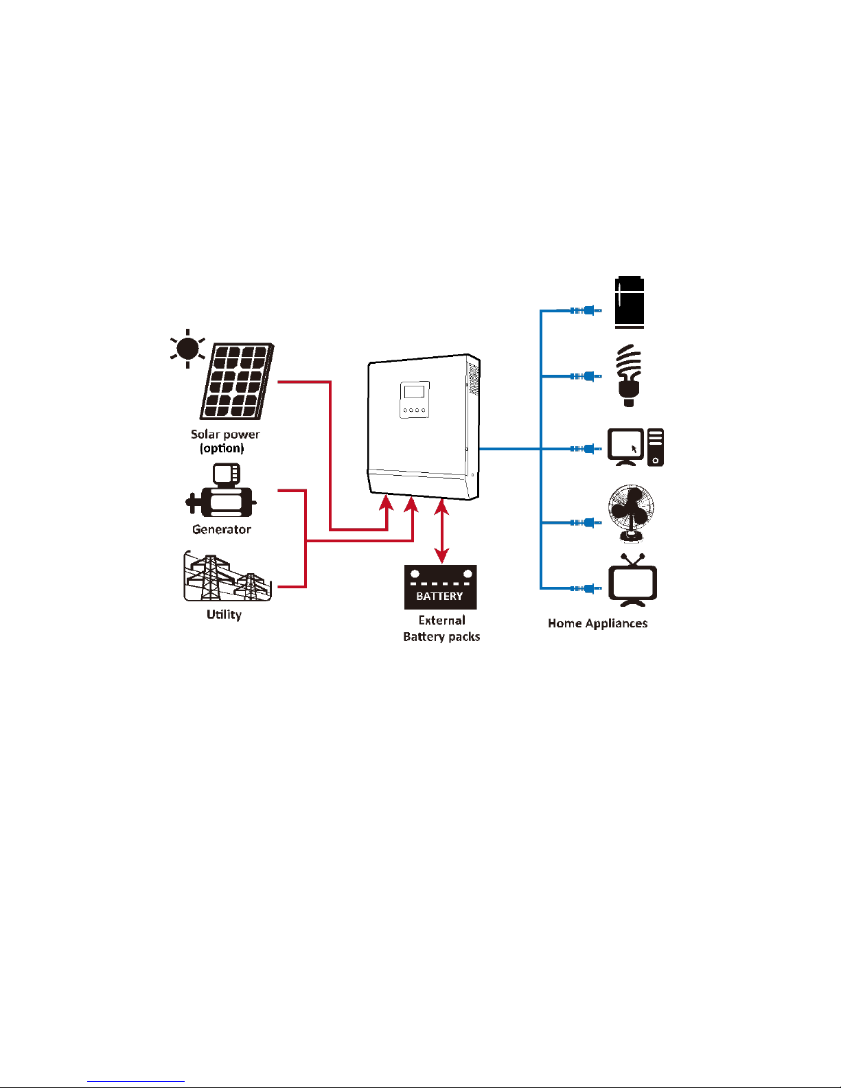
Basic System Architecture
The following illustration shows basic application for this inverter/charger. It also includes following devices to
have a complete running system:
Generator or Utility.
PV modules (option)
Consult with your system integrator for other possible system architectures depending on your requirements.
This inverter can power all kinds of appliances in home or office environment, including motor-type appliances
such as tube light, fan, refrigerator and air conditioner.
Figure 1 Hybrid Power System
Note: Appliances like air conditioner need at least 2~3 minutes to restart because it’s required to have
enough time to balance refrigerant gas inside of circuits. If a power shortage occurs and recovers
in a short time, it will cause damage to your connected appliances. To prevent this kind of damage,
please check manufacturer of air conditioner if it’s equipped with time-delay function before
installation. Otherwise, this inverter/charger will trig overload fault and cut off output to protect your
appliance but sometimes it still causes internal damage to the air conditioner.
4
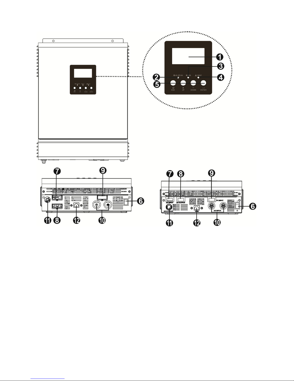
Product Overview
2KVA/3KVA Model 1KVA Model
1. LCD display
2. Status indicator
3. Charging indicator
4. Fault indicator
5. Function buttons
6. Power on/off switch
7. AC input
8. AC output
9. PV input
10. Battery input
11. Circuit breaker
12. Communication port
5
Operation Diagrams and work conditions
Abbreviation:
I
UC
, charging current from AC charger
I
SC
, charger current from solar charger
I
CHG
, total charging current of battery
I
DISC
, discharging current from battery
I
LOAD
, output current of AC load
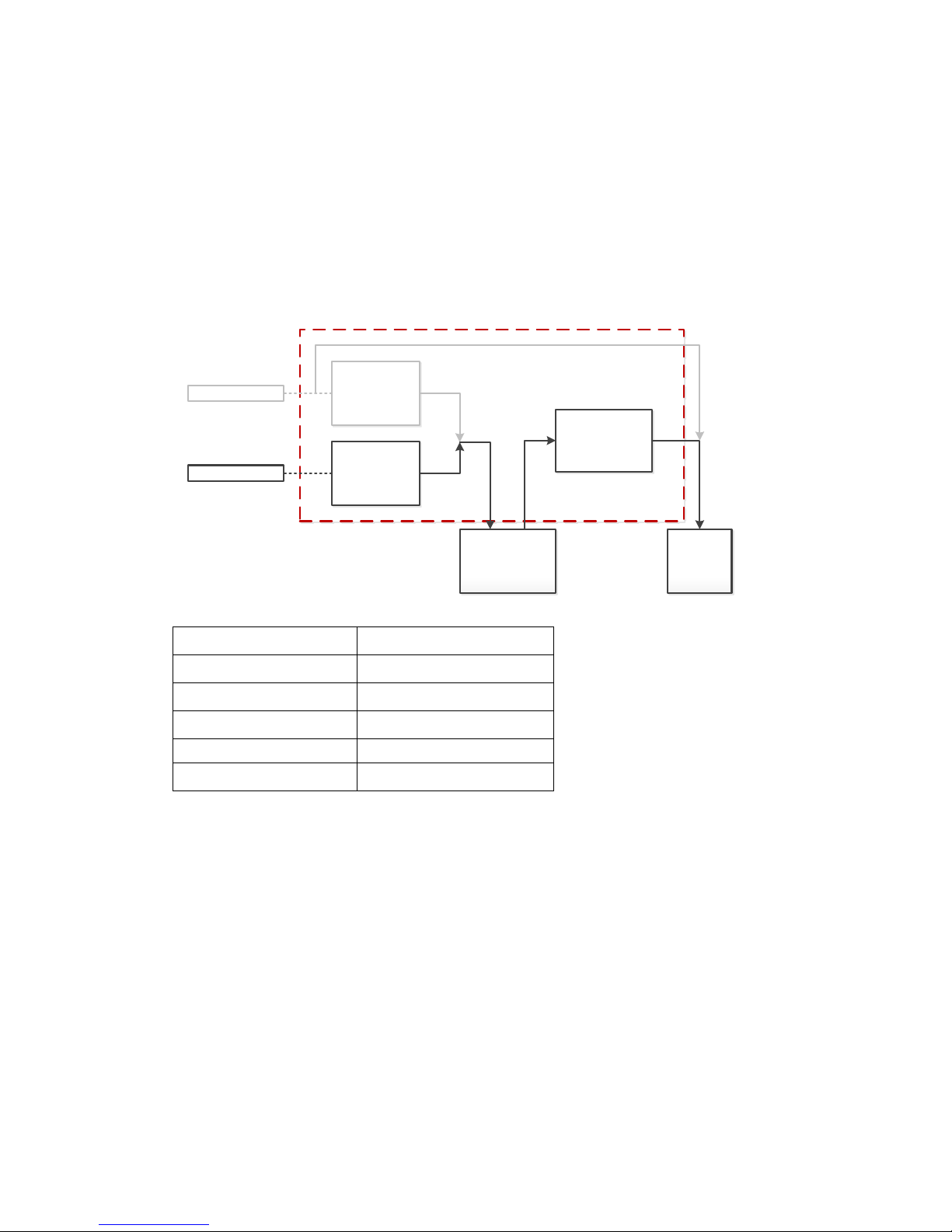
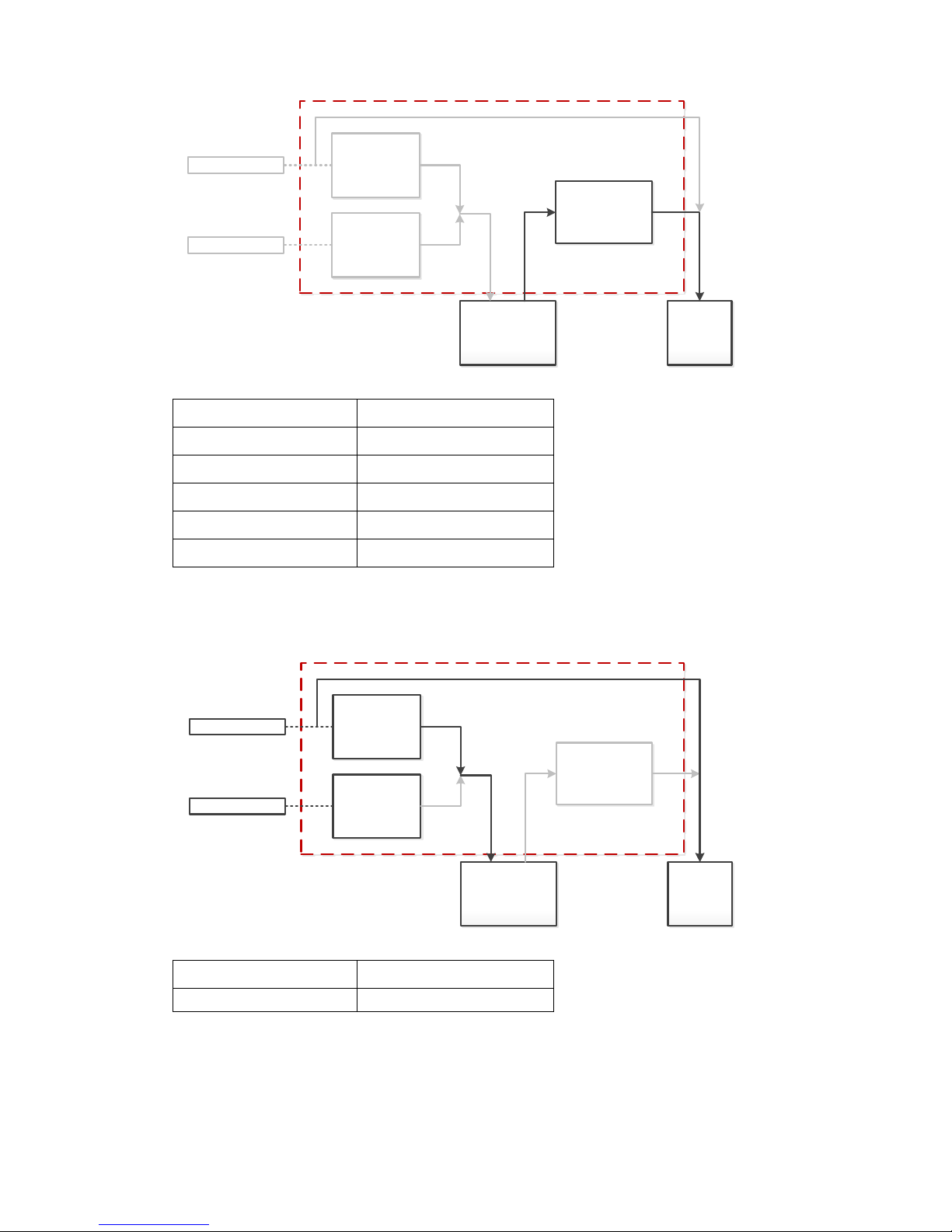
1) When utility source is not present, IUC=0, battery charged from solar source, I
CHG=ISC
, load powered from
solar and battery power, the Max. I
SC
goes up to 50Amp if solar panel with enough energy.
Utility Charger
Solar Charger
Utility Source
Solar Source
Battery Bank
DC/AC Inverter
AC Load
IDISC
ILOAD
ISC
IUC
ICHG
Priority Setting Combinations:
Charger Priority
Output Source Priority
solar
solar
utility
utility
solar
utility
solar and utility
utility
solar and utility
solar
6
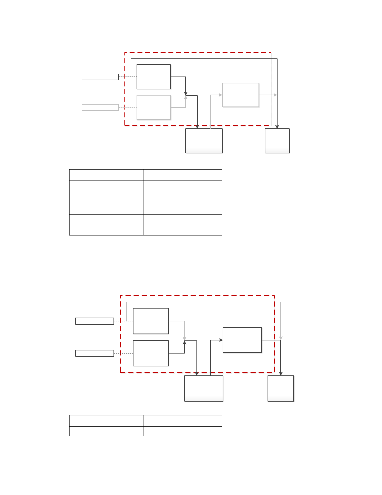
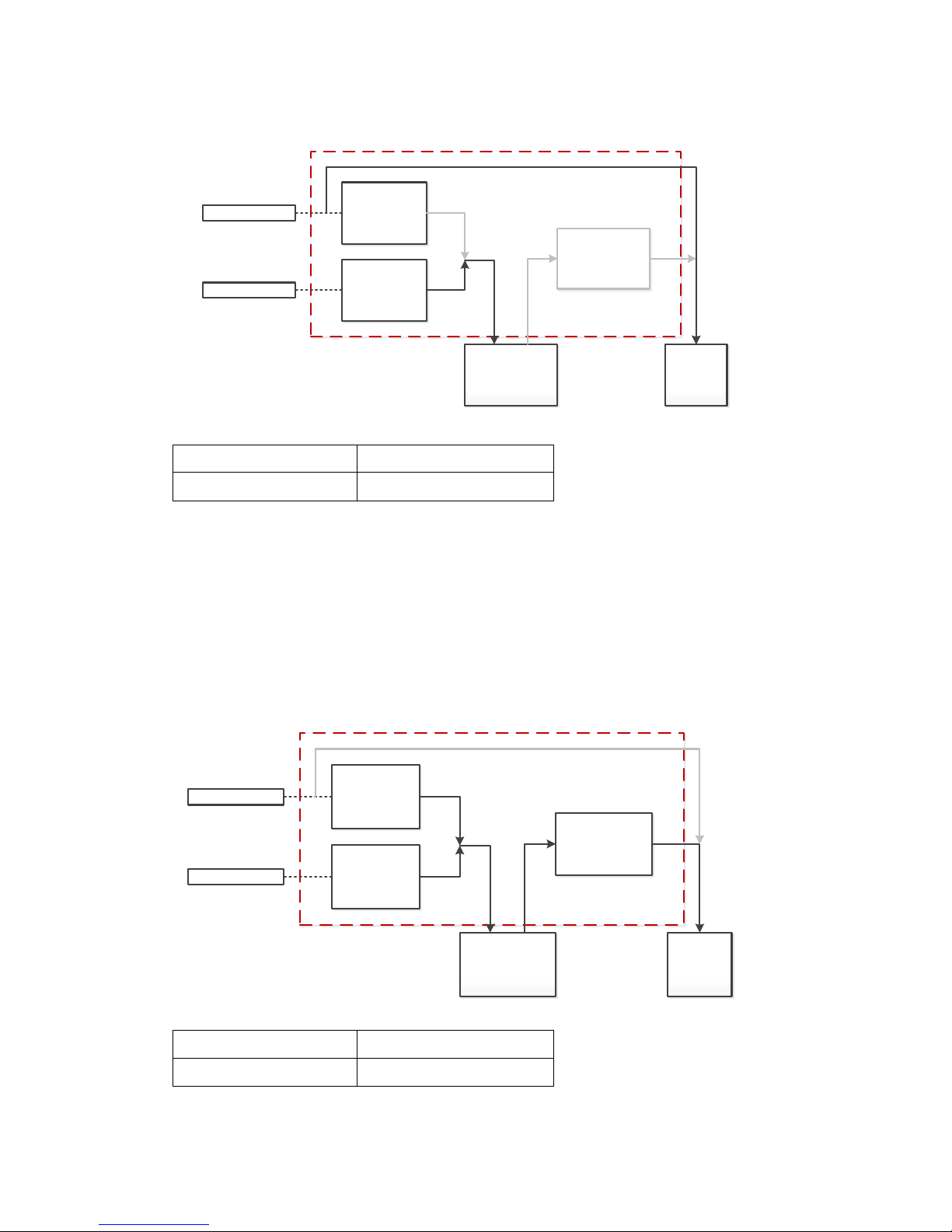
2) When solar source is not present, ISC=0, battery charged from utility source, I
CHG=IUC
, load powered from
utility, the Max. IUC limited at 20Amp for 1KVA, and 30Amp for 2KVA/3KVA.
Utility Charger
Solar Charger
Utility Source
Solar Source
Battery Bank
DC/AC Inverter
AC Load
IDISC
ISC
IUC
ICHG ILOAD
Priority Setting Combinations:
Charger Priority
Output Source Priority
solar
solar
utility
utility
solar
utility
solar and utility
utility
solar and utility
solar
3) When utility and solar are presented, battery charged from solar source, I
CHG=ISC
, load powered from solar
and battery, the Max. ISC goes up to 50Amp if solar panel with enough energy. Output source and charger
source will be turned to utility side in case solar panel without enough energy and battery voltage down to
pre-alarm level.
Utility Charger
Solar Charger
Utility Source
Solar Source
Battery Bank
DC/AC Inverter
AC Load
IDISC
ILOAD
ISC
IUC
ICHG
Priority Setting Combinations:
Charger Priority
Output Source Priority
solar
solar
7
4) When utility and solar are not present, IUC=ISC=0, connected load will be powered from battery.
Utility Charger
Solar Charger
Utility Source
Solar Source
Battery Bank
DC/AC Inverter
AC Load
IDISC
ILOAD
ISC
IUC
ICHG
Priority Setting Combinations:
Charger Priority
Output Source Priority
solar
solar
utility
utility
solar
utility
solar and utility
solar
solar and utility
utility
5) When utility and solar are presented, battery charged from utility, I
CHG=IUC
, load powered from utility, the
Max. IUC limited at 20Amp for 1KVA, 30Amp 2KVA and 3KVA.
Utility Charger
Solar Charger
Utility Source
Solar Source
Battery Bank
DC/AC Inverter
AC Load
IDISC
ISC
IUC
ICHG ILOAD
Priority Setting Combinations:
Charger Priority
Output Source Priority
utility
utility
8
6) When utility and solar are presented, battery charged from solar, I
CHG=ISC
, load powered from utility, Max. ISC
goes up to 50Amp if solar panel with enough energy. Charger source will be turned to utility side in case solar
panel without enough energy.
Utility Charger
Solar Charger
Utility Source
Solar Source
Battery Bank
DC/AC Inverter
AC Load
IDISC
ISC
IUC
ICHG ILOAD
Priority Setting Combinations:
Charger Priority
Output Source Priority
solar
utility
7) When utility and solar are presented, battery charged from both solar and utility, I
CHG=ISC+IUC
, load powered
from solar and battery. Output source will be turned to utility side in case battery voltage down to pre-alarm
level.
Ex. 3KVA Model, AC Load = 2000W
i.e. I
LOAD
≈ 8.7Amp and I
DISC
≈ 92Amp
Max. I
CHG
= 50Amp, it means battery always stay in discharge situation since the required power of AC load is
larger than charging. Once battery down to pre-alarm level, AC load will be powered from utility then I
DISC
become zero.
Utility Charger
Solar Charger
Utility Source
Solar Source
Battery Bank
DC/AC Inverter
AC Load
IDISC
ILOAD
ISC
IUC
ICHG
Priority Setting Combinations:
Charger Priority
Output Source Priority
solar and utility
solar
 Loading...