

OptiPure OP350 Installation Manual

OP350
Advanced Membrane
Separation System
Installation, Operation
& Maintenance Manual
Rev. 2
OP350_iom-manual_v2.indd
©2015 Procam Controls, Inc. All Rights Reserved
Manufactured By:
OptiPure Div. of
Procam Controls, Inc.
2605 Technology Drive, Bldg. 300
Plano, TX 75074
P: 972.881.9797 F: 972.422.6262
OP350 System Installation, Operation & Maintenance 2
General Information
Safety Warning
Electrical work should be performed by a qualied
electrician in accordance with all applicable
codes and regulations.
Service Contact
For local maintenance and service information
please contact your nearest Authorized Service
Representative. Service inquiries may be directed
to technical support at:
OptiPure div. of Procam Controls, Inc.
2605 Technology Dr. Bldg. 300
Plano, TX 75074 USA
Phone #: 972.881.9797
Fax #: 972.422.6262
E-mail correspondence to:
techsupport@optipure.net
Safety Instructions
1. Please read and follow these instructions
when connecting and using the system.
2. To avoid electrical shock, never touch the
inside of the electrical box. Only a qualied
technician should open the electrical box.
3. Never use the system if the power cord or
oat switch cable has been damaged. Do not
allow anything to rest on the power cord or
oat switch cable, and keep the cords away
from any place where people may trip over
them.
4. When disconnecting from the electric socket
hold the plug, not the cord.
5. If the processor does not function properly,
especially if there is an unusual sound or
smell coming from it, immediately unplug
the processor. Call your authorized service
representative.
Environmental Conditions
The OP350 is certied to operate under the
following conditions:
1. Altitude up to 2000 m.
2. Ambient temperature of 40-105°F (5 - 40°C).
3. Max relative humidity 80% at 88°F (31°C).
4. Main supply voltage not to exceed +/- 10%.
5. Installation category II.
6. Pollution degree II.
7. Indoor use only, protect from elements.
Explanation of Symbols
The following symbols are used on the water
processor. The symbols and their explanation is
given below:
Earth ground:
6. Unplug the processor and RP pump from the
AC outlet prior to any service.
7. Locate the RP Assembly as close as possible
to an AC outlet.
8. Securely bolt processor to wall before
operating.
9. Avoid cross-connections and install on cold
water supply only.
10. Use approved Air-Gaps when connecting to
drain lines.
11. Do not exceed system pressure rating and
use water hammer arrestors when water
hammer is evident.
12. Turn off Feed-Water supply before lter or
membrane cartridge replacement.
WARNING: Hazardous Voltage:
OP350 System Installation, Operation & Maintenance 3
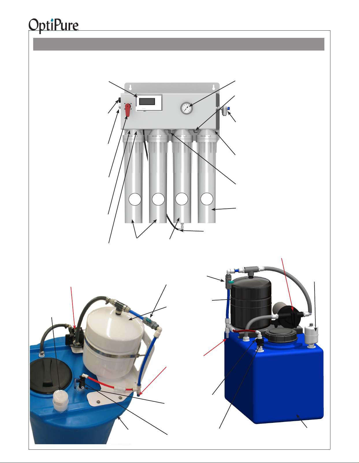
Getting To Know Your System
The OP350 Advanced Membrane Separation System is designed to purify feed water and remove dissolved minerals, and
then add back a consistent amount of a balanced blend of TDS (Total Dissolved Solids), or mineral content, in the treated
water, providing an Optimized Water to your equipment with the characteristics that you desire.
Water Quality Indicator - Operates
momentarily, push purple button to turn
on. Push “IN” button for the TDS of the
water going into your equipment. Push
“OUT” button for the TDS of the puried
water from the membrane.
120VAC
Power Cord
- Plug in to standard
wall outlet.
Feed water
Inlet 3/8” Push-To-
Connect -
Connect to Water Supply
Valve.
Emergency
Bypass Valve -
User can switch from
Optimized Water to
Untreated Water
when needed.
Reject Water Outlet
(behind lter) - 1/4” Push-
to-Connect - Connect to
drain per local regulations.
Reject Flow
Control Valve
(behind lter)
Repressurization Pump
120VAC - Plug in to standard
wall outlet.
Absolute 0.2
micron
Hydrophobic
Air-Breather/
Filter
1
2@ CTO-Q
Pre-Filters
PN: 300-05830
2
3 4
AMS-QT
Membrane
Cartridge
Buffer Tank Valve
Normally open, shown
closed. Used to shut off
water supply to downstream equipment.
Buffer Tank - Pre-charged
air bladder - 20 psi
Tank Level Float
Switch Cable (on
back side of tank)
- Connect to Processor
“Tank Electrical Connection.”
Membrane Reject Water
Tubing Connection
Operating
Pressure Gauge
Optimized Water
To Storage Tank
- 3/8” Push-To-Connect - Connect to
Optimized Water Storage Tank Inlet
Sample Port -
3/8” Push-to-Connect - Used ONLY to ush
pre lters, gather a water sample, measure
production, or drain water from storage tank.
Pressurized
Optimized Water Outlet -
1/2” gray hose
-Connect to End User Equipment
Tank Repressurization Return-
1/2” gray hose - Connect to Repressurization Assembly Outlet
MA-Q15 Mineral
Addition Cartridge
Repressurization Pump
120VAC - Plug in to standard
wall outlet.
Absolute 0.2
micron
Hydrophobic
Air-Breather/
Filter
Optimized Water
Storage Tank
- 50 gal. Atmospheric
Repressurization
Assembly Outlet
- 1/2” Hose Barb Connect to Pressurized
Water Inlet on Processor
Optimized Water to
Storage Tank Inlet - 3/8”
Push-to-Connect - Connect
to Optimized Water Outlet on
Processor.
Tank Inlet Divert Valve
- Normally in Down position. Turn handle
to Up position to divert Optimized water
to sample port.
Optimized Water
Storage Tank
- 16 gal. Atmospheric

OP350 System Installation, Operation & Maintenance 4
Installation Requirements
This section and the next provide the water, electrical
and space requirements for the OP350. Pay
special attention to the feed-water chemistry
requirements. Operating a system on water supplies
outside of these parameters may lead to premature
membrane failure. This product is for commercial
use only and must be installed and maintained in
accordance with manufacturer’s guidelines and local
regulatory plumbing and electrical codes.
Operating parameters
Typical Membrane TDS* rejection:
97+%
Feed Temperature: 40 - 100° F (4 - 38° C)
Feed pressure: 50 - 80 psi
(3.4 - 5.9 bar) at 1 gpm
Production** (at 77°F, 60 psi)
350 gals/day,
14.6 gals/hr, 0.24 gpm
Recovery: up to 33%.
IMPORTANT NOTE: The nominal production rate
is strictly dependent on feed water temperature and
pressure. Reduced temperature or pressure will
reduce production. For example: Operating pressure
of 30 psi will cut production by 50%. 48˚F feedwater
will cut production by 50%.
Location
The system should be installed indoors, in the
proximity of the equipment (within 25 feet) and
protected from the elements. Do not let the processor
or storage tank freeze or be exposed to rain or direct
sunlight.
Additional Optional Post-treatment
Treated water stored in a tank may absorb organic
compounds from the tank, which can affect water
taste and odor. If product water is for consumption, an
optional post-treatment lter, such as an OptiPure
FX or QT carbon lter, should be installed after the
tank. If used, it is best installed as close to the point of
use as possible. Other specialized post-treatment is
also available.
Feed water connection
An adequate ow and pressure of water to the unit is
essential for successful operation. Provide a dedicated
1/2” water line to the vicinity of the installation. Install
a full-ow ball valve and pressure gauge with 1/2”
female pipe thread (user supplied) for connection to
installation hardware provided with the system. A 1/2”
*TDS (total dissolved solids) create conductivity in water and are
expressed in ppm or mg/l (parts per million or milligram per liter).
**Nominal production @ 77°F (25°C) @ 500 ppm based on a 24
hr day. Actual production will vary based on variations in water
temperature, pressure, and TDS.
male pipe thread x 3/8” push-to-connect adapter is
included in the installation kit.
Drain
A drain should be located within 5 feet of the location
of the unit. Drain must allow a minimum ow of 2
gallons per minute. Compliance with most local
plumbing codes requires installation of an approved air
gap in the drain line. The drain connection should be
accessible for system set-up and service.
Electrical requirements
A power source with two outlets should be located
within 5 feet of the location of the unit.
Processor 120V, 60Hz 6 Watts
RP Pump 120V 60Hz 2 Amps
Feed-water chemistry
Feed TDS Up to 1200 ppm
Feed pH 6 - 10
Hardness 28 grains or less
Free chlorine <2 mg/l
Iron (Fe) 0.1 mg/l max.
Turbidity <0.05 NTU
Manganese 0.05 mg/l max.
Hydrogen sulde 0.0 mg/l
A water analysis must be conducted before installing
the system, or the information requested above can
be obtained from your local water utility. If your water
analysis shows that any of these parameters are not
within range, additional pretreatment and/or higher
frequency of maintenance may be required. Contact
your OptiPure distributor for assistance. The presence
of silica or occulants such as alum or cationic
polymers in the feedwater may cause membrane
fouling and may require special chemical pretreatment
or periodic membrane cleaning. Please note that
membrane failure due to fouling is not covered by the
warranty.
Storage Tank
The tank must be located within 10 feet of the water
processor unit. The oor beneath the storage tank
should be smooth, clean and free of sharp objects that
could puncture the bottom of the tank. Note: The tank
is atmospheric, with a sub-micron, hydrophobic air
breather lter.
Optimized Water Lines to Equipment
Tubing, piping and associated ttings connecting
Optimized water lines to equipment shoud be food
grade material that meets NSF Std 51 or 61 with a
minimum pressure rating of 75 PSI. Optimized water
may react with most metal piping imparting a bad
taste. Plastic pipe or reinforced opaque beverage
tubing are acceptable choices for Optimized water
distribution. The larger inside diameter tubing or hose,
the better to minimize pressure drop.
OP350 System Installation, Operation & Maintenance 5
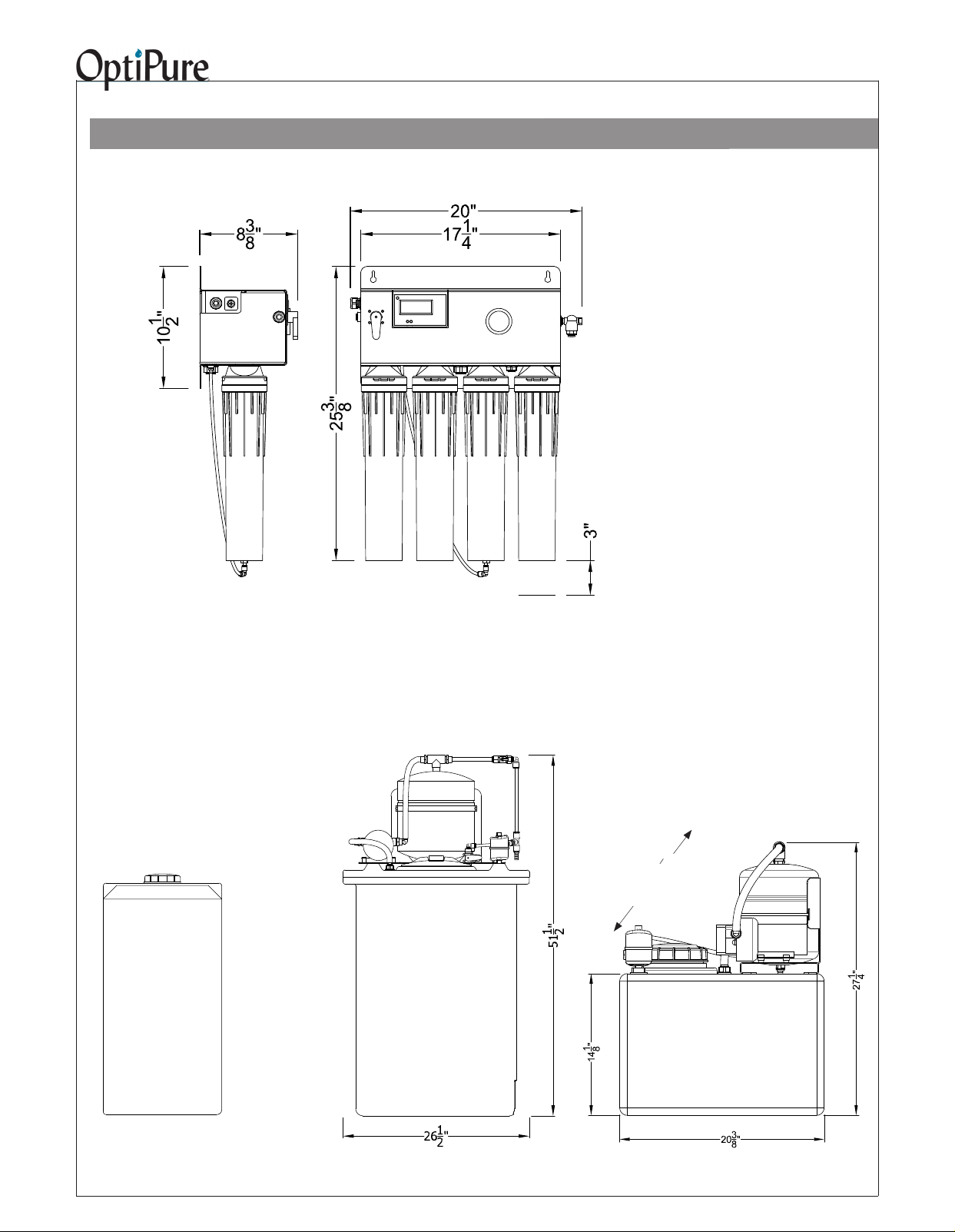
Equipment Dimensions
IMPORTANT - ALLOW A MINIMUM
OF 24” IN FRONT OF THE PROCESSOR FOR MAINTENANCE
AND SERVICE. DO NOT MOUNT
SYSTEM ABOVE THE CEILING OR
IN A LOCATION THAT IS NOT EASILY ACCESSIBLE. WHEN THE 50
GAL. TANK ASSEMBLY IS FULL OF
OPTIMIZED WATER IT WILL WEIGH
450 LBS (THE 16 GAL. TANK, 140
LBS). ALWAYS LOCATE THE
STORAGE TANK WHERE IT CAN BE
ACCESSED (OR IS ACCESSIBLE)
DURING SERVICE.
Processor
Left Side
View
Optional Atmospheric
Storage Tank
175 Gallon Tank,
31” dia. x 68” tall
Processor
Front View
Tank Assembly (50 gal.)
Allow 3”
to remove
cartridges
Tank Assembly (16 gal.)
”
1
4
Width 14
Right Side View
OP350 System Installation, Operation & Maintenance 6
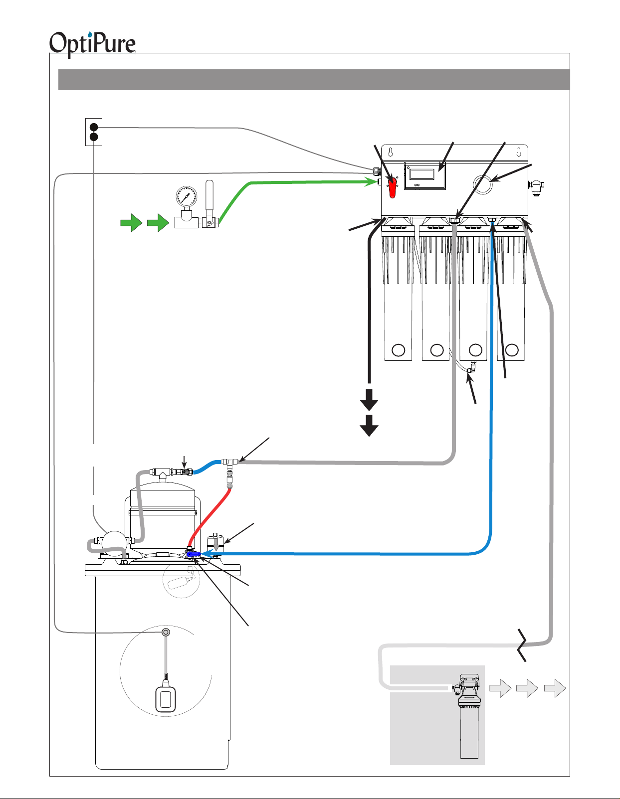
Typical Installation with 50 Gal. Atmospheric Tank
Important: Plumbing should be performed by a qualied plumber in accordance with local codes.
Tank
Repressurization
Return
Pressure
Gauge
Power
120VAC, 2A
Power Cord
Tank Switch Cable
Processor
Emergency
Bypass Valve Operating
Water Quality
Monitor
Feed
Water
When installing keep lines from the
Repressurization Assembly to the equipment as
short as possible to minimize pressure loss.
IMPORTANT - PROTECT PROCESSOR AND
REPRESSURIZATION ASSEMBLY FROM THE
ELEMENTS. DO NOT INSTALL IN DIRECT
SUNLIGHT OR WHERE EXPOSED TO FREEZING
TEMPERATURES OR RAIN. NEVER USE COPPER PIPE FOR OPTIMIZED WATER.
Repressurization
Assembly
Repressurization
Pump
120VAC
User-Supplied
Water Supply
Valve &
Pressure Gauge
Buffer Tank Valve
(Normally Open)
Buffer
Tank
Bypass
Feed Water Line -
Green - from Water Supply
Valve to Feed Water Inlet
Reject Water
Outlet
(behind lter)
Repressurization
Assembly Outlet
(Hose Barb)
Pressurized Water Line
- 1/2" Gray Hose with hose barb inserts at both
ends - from Repressurization Assy Outlet to Tank
Repressurization Return
Air
Breather
Feed
Water
Inlet
CTO-Q
Pre-Filter
Drain Line - Black -
from Reject Outlet to Drain
1
Reject
Water
(to Drain)
CTO-Q
Pre-Filter
2
AMS-QT
Membrane Cartridge
QTMA15-1
3 4
Optimized
Water
to Storage
Tank
Connection
Water Tubing
Membrane Reject
Sample
Port
Optimized
Water
Outlet
to Eqpt
Mineral Addition
Safety Float
Valve
(inside tank)
Optimized Water
Storage Tank
- 50 gal. Atmospheric
Processor
Control Float
Switch
(inside tank)
Optimized
Water to
Storage Tank
Inlet (on valve)
Tank Inlet
Divert Valve
(Valve normally
in Down position.
Turn to Up position
to bypass Repres-
surization Assy.)
Optimized Water Line - Blue
- from Optimized Water Outlet to MA PostTreatment, & from MA Post-Treatmt to Tank Inlet
Optional
Carbon
PostTreatment
Optimized Water Line - 1/2" Gray Hose
with hose barb insert - Make connection to
distribution and (optional) post-treatment.
Optimized
(Treated)
Water to
Equipment
 Loading...