

OP175
Advanced Membrane
Separation System
Installation, Operation
& Maintenance Manual
Rev. 1
OP175_manual_v1.indd
©2010 Procam Controls, Inc. All Rights Reserved
Manufactured By:
OptiPure Div. of
Procam Controls, Inc.
2605 Technology Drive, Bldg. 300
Plano, TX 75074
P: 972.881.9797 F: 972.422.6262
OP175 System Installation, Operation & Maintenance 2
General Information
Safety Warning
Electrical work should be performed by a qualied
electrician in accordance with all applicable
codes and regulations.
Service Contact
For local maintenance and service information
please contact your nearest Authorized Service
Representative. Service inquiries may be directed
to technical support at:
OptiPure div. of Procam Controls, Inc.
2605 Technology Dr. Bldg. 300
Plano, TX 75074 USA
Phone #: 972.881.9797
Fax #: 972.422.6262
E-mail correspondence to:
techsupport@optipure.net
Safety Instructions
1. Please read and follow these instructions
when connecting and using the system.
2. Never use the system if the power cord has
been damaged. Do not allow anything to rest
on the power cord, and keep the cord away
from any place where people may trip over it.
3. When disconnecting from the electric socket
hold the plug, not the cord.
4. Unplug the RP pump from the AC outlet prior
to any service.
5. Locate the RP Assembly as close as possible
to an AC outlet.
6. Securely bolt processor to wall before
operating.
7. Avoid cross-connections and install on cold
water supply only.
Environmental Conditions
The OP175 is certied to operate under the
following conditions:
1. Altitude up to 2000 m.
2. Ambient temperature of 40-105°F (5 - 40°C).
3. Max relative humidity 80% at 88°F (31°C).
4. Main supply voltage not to exceed +/- 10%.
5. Installation category II.
6. Pollution degree II.
7. Indoor use only, protect from elements.
Explanation of Symbols
The following symbols are used on the water
processor. The symbols and their explanation is
given below:
Earth ground:
8. Use approved Air-Gaps when connecting to
drain lines.
9. Do not exceed system pressure rating and
use water hammer arrestors when water
hammer is evident.
10. Turn off Feed-Water supply before lter or
membrane cartridge replacement.
WARNING: Hazardous Voltage:
OP175 System Installation, Operation & Maintenance 3
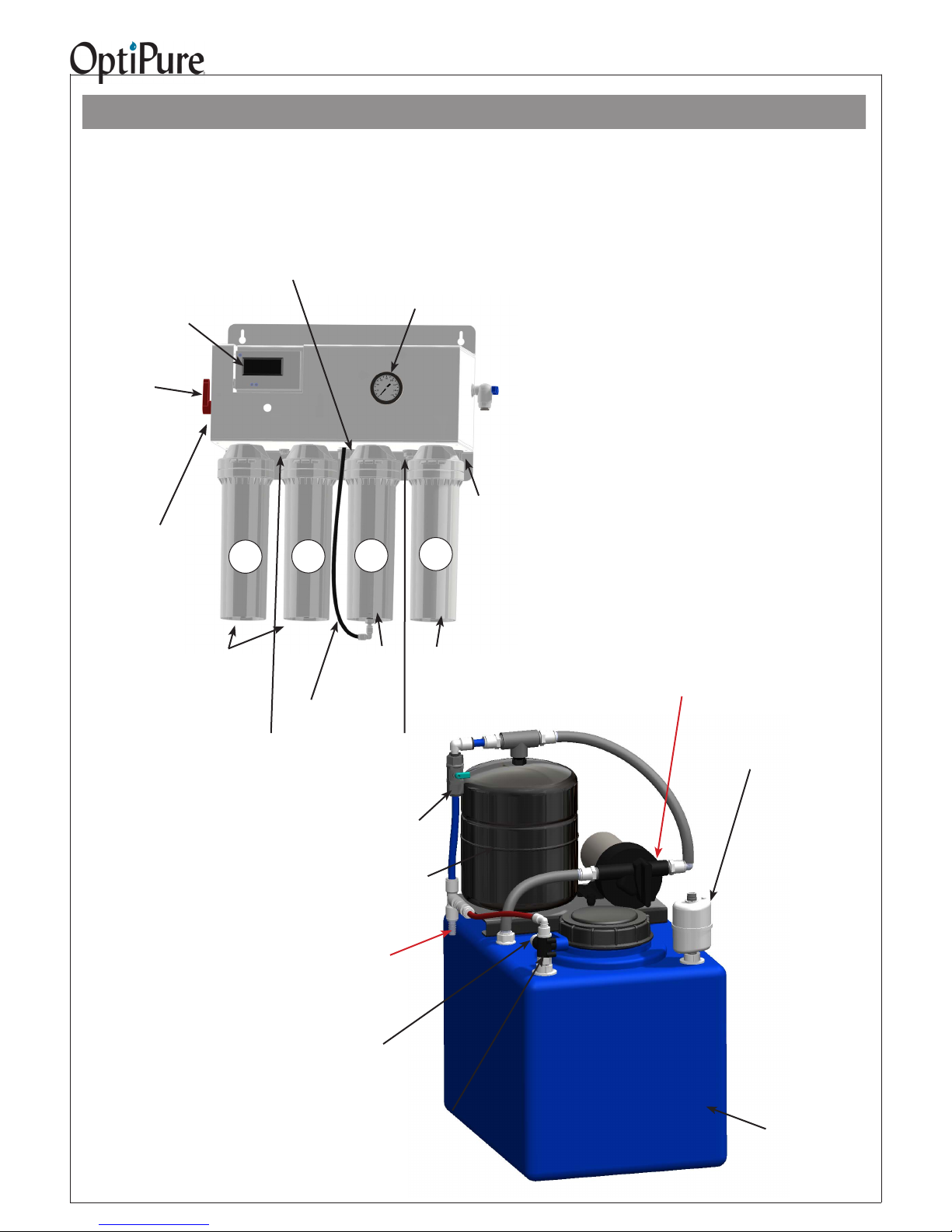
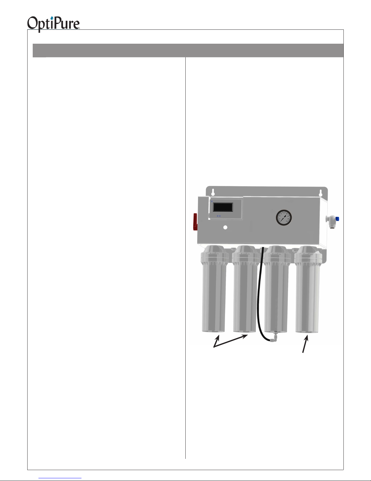
Getting To Know Your System
The OP175 is an Advanced Membrane Separation System designed to purify water by removing dissolved
minerals and then add back a consistent amount of a balanced blend of TDS (Total Dissolved Solids), or mineral
content, in the treated water.
Tank Repressurization
Water Quality Indicator -
Operates momentarily, push purple
button to turn on. Push “IN” button
for the TDS of the water going into
your equipment. Push “OUT” button
for the TDS of the puried water
from the membrane.
Return-
1/2” gray hose - Connect to
Repressurization Assembly
Outlet
Operating
Pressure Gauge
Emergency
Bypass Valve -
User can switch from
Optimized Water to
Untreated Water if
needed.
Feed water
Inlet 3/8” Push-To-
Connect Connect to Water Supply
Valve.
Reject Water Outlet
- 1/4” Push-to-Connect Connect to drain per local
regulations.
1
2@ CTO-Q10
Pre-Filters
PN: 300-05828
2
Membrane Reject Water
Tubing Connection
Optimized Water
To Storage Tank -
3/8” Push-To-Connect
- Connect to Optimized
Water Storage Tank
Inlet
Buffer Tank - Pre-charged
air bladder - 20 psi
3
AMS-QT15
Membrane
Cartridge
Buffer Tank Valve
Normally open, shown
closed.
Pressurized
Optimized Water
Outlet -
4
1@Mineral
Addition
Cartridge
PN: 300-05850
1/2” gray hose
-Connect to End User
Equipment
Sample Port -
3/8” Push-to-Connect - Used to
ush replacement lters, gather
water sample, measure production
or to drain water from storage tank.
Repressurization Pump
120VAC - Plug in to standard
wall outlet.
Absolute 0.2 micron
Hydrophobic AirBreather/Filter
Repressurization
Assembly Outlet
- 1/2” Hose Barb Connect to Pressurized
Water Inlet on Processor
Optimized Water to
Storage Tank Inlet
- 3/8” Push-to-Connect
- Connect to Optimized
Water Outlet on OP175
processor.
Tank Inlet
Divert Valve
- Normally in Down
position. Turn handle to
Up position to divert Optimized water to sample port.
Optimized Water
Storage Tank
- 16 gal. Atmospheric

OP175 System Installation, Operation & Maintenance 4
Installation Requirements
This section and the next provide the water, electrical
and space requirements for the OP175. Pay
special attention to the feed-water chemistry
requirements. Operating a system on water supplies
outside of these parameters may lead to premature
membrane failure. This product is for commercial
use only and must be installed and maintained in
accordance with manufacturer’s guidelines and local
regulatory plumbing and electrical codes.
Operating parameters
Typical Membrane TDS* rejection:
97+%
Feed Temperature: 40 - 100° F (4 - 38° C)
Feed pressure: 50 - 80 psi
(3.4 - 5.9 bar) at 1 gpm
Production** (at 77°F, 60 psi)
184 gals/day,
7.7 gals/hr, 0.13 gpm
Recovery: up to 33%.
IMPORTANT NOTE: The nominal production rate
is strictly dependent on feed water temperature
and pressure. Reduced temperature or pressure
will reduce production. For example: Operating
pressure of 30 psi will cut production by 50%. 48˚F
feedwater will cut production by 50%.
Location
The system should be installed indoors, in the
proximity of the equipment (within 25 feet) and
protected from the elements. Do not let the processor
or storage tank freeze or be exposed to rain or direct
sunlight.
Post-treatment
Treated water stored in a tank may absorb organic
compounds from the tank, which can affect water
taste and odor. If product water is for consumption, an
optional post-treatment lter, such as an OptiPure
FX or QT carbon lter, should be installed after the
tank. If used, it is best installed as close to the point of
use as possible. Other specialized post-treatment is
also available.
Feed water connection
An adequate ow and pressure of water to the unit is
essential for successful operation. Provide a dedicated
1/2” water line to the vicinity of the installation. Install
a full-ow ball valve and pressure gauge with 1/2”
female pipe thread (user supplied) for connection to
installation hardware provided with the system. A 1/2”
*TDS (total dissolved solids) create conductivity in water and are
expressed in ppm or mg/l (parts per million or milligram per liter).
**Nominal production @ 77°F (25°C) @ 500 ppm based on a 24
hr day. Actual production will vary based on variations in water
temperature, pressure, and TDS.
male pipe thread x 3/8” push-to-connect adapter is
included in the installation kit.
Drain
A drain should be located within 5 feet of the location
of the unit. Drain must allow a minimum ow of 2
gallons per minute. Compliance with most local
plumbing codes requires installation of an approved air
gap in the drain line. The drain connection should be
accessible for system set-up and service.
Electrical requirements
A power source should be located within 5 feet of the
location of the unit.
RP Pump 120V 60Hz 2 Amps
Feed-water chemistry
Feed TDS Up to 1200 ppm
Feed pH 6 - 10
Hardness 28 grains or less
Free chlorine <2 mg/l
Iron (Fe) 0.1 mg/l max.
Turbidity <0.05 NTU
Manganese 0.05 mg/l max.
Hydrogen sulde 0.0 mg/l
A water analysis must be conducted before installing
the system or the information requested above can
be obtained from your local water utility. If your water
analysis shows that any of these parameters are not
within range, additional pretreatment and/or higher
frequency of maintenance may be required. Contact
your OptiPure distributor for assistance. The presence
of silica or occulants such as alum or cationic
polymers in the feedwater may cause membrane
fouling and may require special chemical pretreatment
or periodic membrane cleaning. Please note that
membrane failure due to fouling is not covered by the
warranty.
Storage Tank
The tank must be located within 10 feet of the water
processor unit. The oor beneath the storage tank
should be smooth, clean and free of sharp objects that
could puncture the bottom of the tank. Note: The tank
is atmospheric, with a sub-micron, hydrophobic air
breather lter.
Optimized Water Lines to Equipment
Tubing, piping and associated ttings connecting
Optimized water lines to equipment shoud be food
grade material that meets NSF Std 51 or 61 with a
minimum pressure rating of 75 PSI. Optimized water
may react with most metal piping imparting a bad
taste. Plastic pipe or reinforced opaque beverage
tubing are acceptable choices for Optimized water
distribution. The larger inside diameter tubing or hose,
the better to minimize pressure drop.
OP175 System Installation, Operation & Maintenance 5
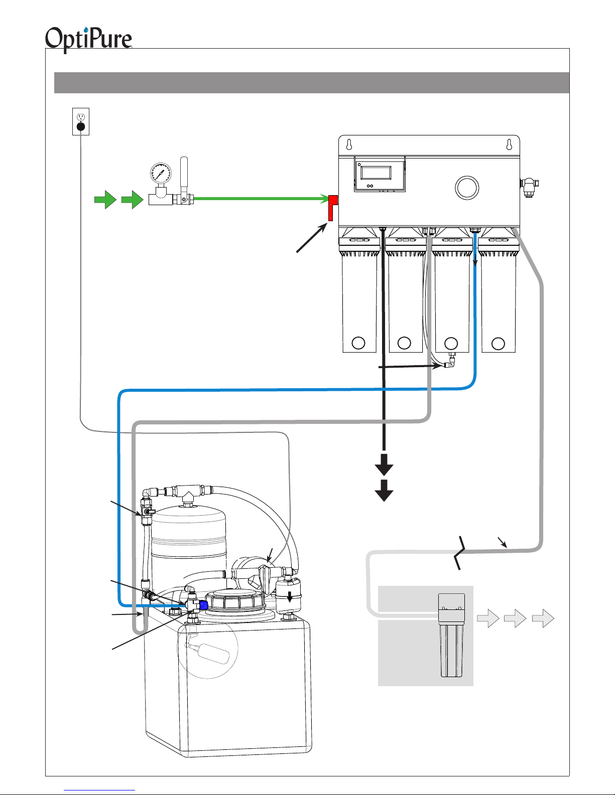
Typical Installation with Atmospheric Tank
Important: Plumbing should be performed by a qualied plumber in accordance with local codes.
Power
120VAC, 2A
Feed
Water
User-Supplied
Water Supply
Valve &
Pressure Gauge
Feed Water Line -
Green - from Water Supply
Valve to Feed Water Inlet
When installing keep lines from the
Repressurization Assembly to the
equipment as short as possible to
minimize pressure loss.
Optimized Water Line - Blue
- from Optimized Water Outlet to Tank Inlet
Pressurized Water Line - 1/2" Gray Hose with hose barb inserts at
both ends - from Repressurization Assy Outlet to Pressurized Water Inlet.
Feed Water Inlet
Connection
(behind valve)
Emergency
Bypass Valve
Membrane Reject Water
Tubing Connection
Processor
Reject
Water
Outlet
CTO-Q
Pre-Filter
1
Water Quality
Monitor
Tank
Repressurizaton
CTO-Q
Pre-Filter
2
Return
Storage Tank
AMS-QT15
3
Operating
Pressure
Gauge
Optimized
Water To
Membrane Cartridge
Mineral Addition
Cartridge
4
Sample
Port
Optimized
Water Outlet
to Equipmt
Buffer Tank Valve
(Normally Open,
shown closed)
Optimized
Water to
Storage Tank Inlet
(on Valve)
Repressurization
Assembly Outlet
(Hose Barb)
Tank Inlet
Divert Valve
(Valve handle
normally in Down
position. Turn to
Up position to
divert Optimized
water to the
sample port.)
Repressurization
Assembly
Buffer Tank
Bypass
Optimized Water
Storage Tank
- 16 gal. Atmospheric
Repressurization Pump
120VAC
Tank Full
Shutoff Valve
(inside tank)
Air
Breather
Reject
Water
(to Drain)
Drain Line - Black -
from Reject Outlet to Drain
Optimized Water Line - 1/2" Gray Hose
with hose barb insert - Make connection to
distribution and (optional) post-treatment.
Optional
Carbon
PostTreatment
Optimized
(Treated)
Water to
Equipment
IMPORTANT - THE SYTEM MUST BE INSTALLED INDOORS. DO NOT INSTALL IN
DIRECT SUNLIGHT OR WHERE EXPOSED TO
FREEZING TEMPERATURES OR RAIN. IDEALLY USE NON-METAL PIPING FOR OPTIMIZED
WATER CONDUIT.

Plywood anchored
to wall
OP175 System Installation, Operation & Maintenance 6
Outside edge of
processor bracket
9.1”
10.7”
15.2”
17.2”
Wall Mounting
The processor unit should always be mounted where
it is well-supported, either using anchors in a cement
wall, or using the support of studs in a wall-board
wall. Never mount it directly to sheet-rock alone.
Instead, mount it on a sheet of plywood which is
anchored to the wall studs, as shown above.
Four user-supplied bolts or screws with a head
diameter of approximately 1/2” (which will t into the
keyholes in the system bracket, but will not slip out
when tightened) should be used to hang the system.
This will allow the unit to be lifted off the bolts, if
necessary for maintenance, without removing all
the bolts from the wall. Hold the processor in place
(without the cartridges) to mark the locations for
the screws. BE SURE TO ALLOW 3” BELOW THE
CARTRIDGES TO ALLOW FOR REMOVAL. Screw
the four bolts or screws in place, leaving approximately
1/4” clearance between the bottom of each bolt head
and the wall. Position the system over the mounting
bolts, and let the bracket slip down into the keyholes.
Tighten all screws.
System Installation
Note: Do not install the cartridges in the processor
until completing this section. Do not plug in the
power cord from the RP pump until completing the
following section, “System Start-Up”.
Refer to “Typical Installation” diagram on page 5
and “How to Use Our Quick-Connect Fittings” on
page 16 when making the following connections.
A feed water ball valve and pressure gauge (user
supplied) should be installed to provide water to the
system FEED WATER INLET with the green tubing
(supplied). Hose, tubing and ttings for making
connections between the processor, storage tank
and drain are supplied in the installation kit with the
system.
1. Remove the tank lid. Inside the tank, the oat
valve may be secured for shipping. Remove any
wrapping on the oat to allow it to hang and move
freely.
2. DRAIN: Connect the 1/4” black tubing from the
installation kit to the REJECT WATER OUTLET on
the processor. Run the line to an appropriate drain.
Observe local plumbing codes and supply an
appropriate air gap. (Any ttings for connecting to
the drain will need to be supplied by the customer.)
Fix tubing in place at the drain.
3. FEED WATER: Apply 3 ‘wraps’ of Teon tape to
the 1/2” FPT x 3/8” push-connect tting (supplied).
Screw the tting into the Feed Water Supply Ball
Valve and tighten (DO NOT OVERTIGHTEN).
Connect one end of the 3/8” GREEN TUBING to
this tting. Connect the other end of the tubing to
the FEED WATER INLET located on the left side
of the Processor. Cut the tubing to the required

OP175 System Installation, Operation & Maintenance 7
Equipment Dimensions
IMPORTANT - ALLOW A MINIMUM OF 24” IN FRONT OF THE PROCESSOR FOR MAINTENANCE AND SERVICE.
DO NOT MOUNT SYSTEM ABOVE THE CEILING OR IN A LOCATION THAT IS NOT EASILY ACCESSIBLE. WHEN
THE 16 GAL. TANK ASSEMBLY IS FULL OF OPTIMIZED WATER IT WILL WEIGH 140 LBS. ALWAYS LOCATE THE
STORAGE TANK WHERE IT CAN BE ACCESSED (OR IS ACCESSIBLE) DURING SERVICE.
Processor
Left Side
View
Processor Front View
Tank Assembly (16 gal.)
Allow 3”
to remove
cartridges
Front View Right Side View

OP175 System Installation, Operation & Maintenance 8
Inlet
Repressurization
Assy Outlet
Optimized
Water Inlet
Tank Inlet Divert
Valve- Shown in the
normal positon
length if necessary.
NOTE: When cutting the tubing use a sharp tubing
cutter or blade and make a clean, straight cut
before inserting into a push-connect tting. When
routing tubing, do not make sharp bends or crimp
the tubing.
4. PROCESSOR TO TANK: Connect a piece of
the 3/8” blue tubing to the OPTIMIZED WATER
TO STORAGE TANK tting on the processing
unit. Connect the other end of this tubing to the
OPTIMIZED WATER TO STORAGE TANK INLET
on the storage tank INLET DIVERT VALVE.
5. REPRESSURIZATION ASSEMBLY TO
PROCESSOR: Using two of the 1/2” hose barb
inserts (supplied), a piece of 1/2” gray hose,
and two hose clamps, connect hose from the
REPRESSURIZATION ASSEMBLY OUTLET
on the Repressurization Assembly to the
TANK REPRESSURIZATION RETURN on the
Processor. The ridged end of a hose barb insert
goes into each end of the hose with a hose clamp
tightened onto it. The smooth ends of the hose
barb inserts go into the push-to-connect ttings on
the Processor and Repressurization Assembly.
Water Outlet
1 2
Reject tubing connected to stem connector
on bottom of AMS-QT15 Cartridge
3
4
Install QT Cartridges
NOTE: Before installing the QT Cartridges make sure
to remove the four plugs in the QT heads.
1. Insert the CTO-Q10 cartridges into QT heads
1 & 2 (starting from the left or inlet side of the
processor) and turn to align arrows.
2. Insert the AMS-QT15 membrane cartridge into the
QT head #3 and turn to align arrows.
3. Insert the MA-QT mineral addition cartridge into
the QT head #4 (far right) and turn to align arrows.
4. Connect the Push-to-Connect elbow (remove plug
in elbow) on the end of the black Reject tubing
to the stem connector on the bottom of the AMSQT15 cartridge.
Optimized
6. OPTIMIZED WATER TO EQUIPMENT: Connect
a piece of 1/2” i.d. gray hose the the OPTIMIZED
WATER OUTLET on the processor with a 1/2”
hose barb insert and clamp (supplied). The other
end of this line will be connected to the distribution
line that will deliver Optimized Water to the
equipment at a later time. Prepare any necessary
plumbing to make the connection between the
1/2” hose and distribution line, but for now leave
the line loose and route the loose end of the
gray hose into a drain or bucket (make certain
the hose length will reach the storage tank - this
will be required for the Start-Up procedures).
The equipment connection will be completed in
“Connect to Equipment.”
Optional RP Assembly Location
The Repressurization Pump and Buffer Tank assembly
is on a stand that can be remote from the storage tank.
Simply remove the four bolts on the feet of the bracket
and lengthen the gray hose from the tank to the pump
and the red bypass tubing from the Tank Inlet Divert
Valve to the required length. Four rubber feet and
mounting screws are available to put on the bottom of
the Tank Stand. Kit Part number 164-89116.

OP175 System Installation, Operation & Maintenance 9
System Start-Up
Refer to the illustration in “Typical Installation” (page
5).
from the Optimized Water Outlet on the Processor
to the distribution line feeding the equipment that
will be using the Optimized Water.
IMPORTANT: Before proceeding, position the
Processor EMERGENCY BYPASS VALVE in the
“SERVICE” position, assure that the Buffer Tank Valve
is closed, and position the TANK INLET DIVERT
VALVE to bypass the tank (Blue Valve Handle pointing
up).
1. Slowly open the user-supplied WATER SUPPLY
VALVE and allow the lter housings to ll. Water
will begin to ow from the end of the 1/4” black
tubing routed to the drain. After some time, water
will begin to ow from the gray hose which is
temporarily routed to a bucket or the drain. Allow
several minutes to ush the system until water
ows smoothly from the gray hose and drain line.
Check all of the plumbing connections and correct
any leaks if necessary.
2. The tank must be ll to start-up and purge the
Repressurization Assembly. You can quickly ll the
storage tank using the “System Bypass” on the
processor. To do this use the following:
• Route the 1/2” gray hose from the OPTIMIZED WATER
OUTLET directly into the storage tank.
• Turn the EMERGENCY BYPASS VALVE on the processor
to “BYPASS.” This will allow feed water to bypass the
processor and quickly ll the storage tank.
• When the tank lls to approximately 14 gallons return
the processor EMERGENCY BYPASS VALVE to the
“SERVICE” position. When the tank is full, the shutoff
valve will close, stopping all ow.
• With the tank full, ensure the valve at the top of the BUFFER
TANK is in the OPEN position and that the 1/2” gray hose is
still directed into the storage tank.
3. Plug the power cord from the RP pump into the
outlet. Water should begin to ow rapidly from the
storage tank, through the RP assembly and back
into the storage tank through the gray hose. Allow
the pump to run for several minutes until all of the
air is purged from the Repressurization Assembly.
As the air is purged, the pump will run more
smoothly and the water ow from the gray hose
will become steady.
4. Unplug the RP Pump cord.
Connect to Equipment
You are almost ready to enjoy the benets of
Optimized Water. All that remains is to make the
connection for distribution to your equipment.
3. Ensure that any valves or solenoid valves on the
connected equipment are closed. Plug the RP
pump back in. The pump will run and will ll the
Buffer Tank until the pressure in the Buffer TAnk
reaches 70 psi, and then the RP Pump will shut
off.
4. Open downstream valves at the equipment to
allow air to purge from the distribution lines. When
purging distribution lines do not allow the water
level in the storage tank to drop below 1/4 full.
Once purged and ushed, close the equipment
valves. When there is no demand for water the
pump will shut off automatically.
5. Turn the TANK INLET DIVERT VALVE to the
“TANK” position (blue valve handle pointing down).
Complete the Installation
Transition to Owner/Operator
The nal step is to meet with the owner/operator,
familarize them with the system and complete the post
installation check list.
The system is now in “normal operating” mode and
the storage tank will ll with Optimized Water from
the processor. Complete the “Check List” to “Conrm
Normal Operation and System Settings” (page 4 of the
“Quick Installation Guide”) with the Owner/Operator.
Allow the tank to ll before beginning operation of the
connected equipment.
Reading the TDS
1. Push the purple “POWER” button on the Water
Quality Monitor located on the upper left corner.
It will immediately display the “IN” or Optimized
Water TDS (Total Dissolved Solids) in PPM
(parts per million). Document this number as the
Optimized Water TDS.
2. Within 30 seconds, push the “OUT” button to
display the Membrane Permeate TDS and record
this number as the Permeate TDS.
1. Remove the 1/2” gray hose from the storage tank
and replace and tighten the lid to the storage tank.
2. Complete the connection of the 1/2” gray hose

OP175 System Installation, Operation & Maintenance 10
What are all those parts and what do they do?
3
FEED
9
1
1
4.
4
8
6
PG
7
13
5
10
2
Sample Port
To User
Equipment
20
To Drain
18
15
16
This section will give you an overview of how
the system works.
• Incoming water is ltered by the prelters
(1), which remove sediment, chlorine and
organics.
• When the Emergency Bypass Valve (3) is
in the normal SERVICE mode, water ows
through the Processor. When the Bypass
Valve (3) is in System Bypass mode, the
water is diverted directly out to the equipment,
bypassing both the Processor and the
Repressurization Assembly.
• When water in the storage tank is at a low
storage level, the oat valve at the tank
(12) opens, lowering the pressure in the
Optimized Water line from the Processor to
the Repressurization Assembly, causing the
Automatic Shutoff Valve (4) in the Processor
to open, allowing feed water to ow through to
the AMS-QT15 membrane (7).
• The membrane feed water pressure is
indicated by the pressure gauge (6).
• The water ows to the inlet of the membrane
(7). The water is split by the membrane into a
pure water stream and a reject water stream.
The reject water ows to the Reject Flow
Control (10) and then on to drain.
17
14
19
Storage
Tank
11
12
• The pure water stream continues through the
Permeate Check Valve (8), and through the
Mineral Addition cartridge (2), then on to the
tank through the Tank Inlet Divert Valve (11)
on top of the Storage Tank (14). Air in the
tank is displaced by the incoming water and
vented out of the Sub-Micron Air Breather
(16).
• When the tank completely lls, the tank
oat valve (12) closes, causing pressure
in the Optimized Water Line to rise, which
then causes the Automatic Shutoff Valve
(4) to close, stopping the ow through the
Processor.
• When the “IN” button is actuated on the
Water Quality Monitor (9), it measures the
average TDS of the Optimized Water in
the Pressurized Water Line coming from
the storage tank. When the “OUT” button
is actuated, the Water Quality Monitor (9)
indicates the TDS of the Permeate water
exiting the Membrane (7). If the Bypass Valve
(3) is in System Bypass mode, the Water
Quality Monitor (9) will measure the TDS of
the untreated Feed Water when the “OUT”
button is actuated. The Water Quality Monitor
(9) is battery powered with two AA batteries. It
will automatically shut-off after 30 seconds.

OP175 System Installation, Operation & Maintenance 11
• The Repressurization Pump (15) is designed
to draw water from the Atmospheric Storage
Tank (14) and dispense the Optimized water
to the Processor and through the One-Way
Check Valve (5) and out to the equipment.
A Buffer Tank (18) between the pump and
the downstream equipment to prevent short
cycling of the pump for low volume demands.
The Repressurization Pump is equipped with
a pressure switch so that when the pressure
in the Buffer Tank drops, the Pump runs to
repressurize the Buffer Tank, and when the
pressure reaches 70 psi, the Pump shuts off.
• Water demand for downstream equipment is
directly supplied from the Buffer Tank (18),
and demand can go on and off as necessary.
The RP Pump is not directly affected by
downstream demand, but only activates in
response to a sufcient drop in Buffer Tank
pressure. Downstream equipment is also not
affected by the automatic starting or stopping
of the RP Pump.
• The Optional Post-Treatment Filter (20) is
designed to provide additional treatment
based upon specic application requirements.
For beverage applications an activated
carbon lter is recommended.
• As Optimized Water is dispensed from the
storage tank by the Repressurization Pump
(15), air is replaced in the tank through the
Sub-Micron (0.2 micron) Air Breather (16).
• If the Repressurization Pump (15) fails, water
ow and can be restored to the equipment by
turning the Emergency Bypass Valve (3) to
the position to “SYSTEM BYPASS” position.
This allows tap water to bypass the processor
and RP assembly.
Repressurization Pump
The Repressurization Pump Assembly that comes
standard with the OP175 System includes a
diaphragm pump controlled by a built-in Pressure
Switch, and a Buffer Tank between the Pump and
the downstream equipment maintains pressure
downstream. When a valve or solenoid valve is
opened down-stream of the Buffer Tank, the demand is supplied from the Buffer Tank. When the
pressure drops sufciently in the Buffer Tank, the
pump starts automatically and rells the Buffer
Tank. The operating pressure for the Buffer Tank
is preset (to 70 psi) and is NOT eld adjustable.
The pump also incorporates check valves to keep
the Buffer Tank and downstream line pressurized.
The pump is equipped with auto-reset, thermal
overload protection and is designed for intermittent duty.
If the pump runs erratically, allow the pump
to run to open drain with valve fully open to
purge air from the pump head. Disconnect the
power and reconnect several times to facilitate air purging.
Pump will prime only if all the pressure is relieved
from the outlet port. The pump is self-priming up
to 11 ft. The pump can run dry but will overheat
and the pump overload will shut the pump off.
• A Sample Port (13) provides the ability to
measure membrane production by closing
the Buffer Tank Valve (17) and turning the
Tank Inlet Divert Valve (11) to the bypass
or UP position. This diverts the permeate
(pure water produced by membrane) from the
Storage Tank (14) through the Bypass Check
Valve (19) and back to the processor where
opening the Sample Port (13) will allow you to
directly measure the permeate ow rate.
• Additionally the Sample Port (13) provides
the ability to drain water from the Storage
Tank (14) by closing the user-supplied Water
Supply Valve, opening the Buffer Tank Valve
(17) and opening the Sample Port (13).

OP175 System Installation, Operation & Maintenance 12
OP175 Processor Components
Automatic Shutoff
Valve -
PN: 524-20010
“IN” Optimized
Water Conductivity
Probe -
Pressure Gauge -
PN: 530-20018
Green Tubing -
Filtered Water Line
Blue Tubing -
Optimized Water
Line
Red Tubing -
Bypass Water
Line
Reject Flow Control -
PN: 564-02105
Water Quality Monitor -
PN: 530-40112
Bypass Valve -
PN: 520-12230
Sample Port
Valve -
PN: 520-12223
“OUT” Permeate
Conductivity Probe
Mineral Addition
Cartridge -
PN: 300-05850
AMS-QT15 Cartridge -
PN: 204-52820
Stem Connector -
PN: 551-65210
Union Elbow -
PN: 551-63021
Pressurized
Water Check
Valve -
PN: 524-01035
Permeate
Check Valve -
PN: 524-01030
Black Tubing -
Reject Water Line
CTO-Q10 PreFilters (x2) -
PN: 300-05828

OP175 System Installation, Operation & Maintenance 13
Tank/RP Components
Buffer Tank Valve -
PN: 520-14501
Bypass
Check Valve-
PN: 524-01030
Buffer Tank -
PN: 340-50001
RP Pump -
PN: 704-35513
Tank Bracket -
PN: 594-80516
RP Assy
Outlet -
1/2” Hose Barb
Insert,
PN: 550-08730
Connect to
equipment inlet.
Optimized Water Inlet -
Connect line from Optimized
Water To Storage Tank Outlet
on OP175 processor.
Tank Inlet Divert Valve -
PN: 520-12235
Air Breather -
PN: 300-40005
Float Valve -
(inside tank)
PN: 520-01203
16 Gal Storage
Tank -
PN: 570-00016
OP175 System Installation, Operation & Maintenance 14
Routine Maintenance: Filter Change Procedure
The only routine maintenance required on the
system is periodic replacement of the carbon/
sediment pre-lters and the mineral addition
cartridge. The CTO-Q10 cartridges should be
changed every 3-6 months depending on water
usage. In areas with high levels of sediment and
other contaminants the CTO-Q10 cartridges may
require more frequent changes. The mineral
addition cartridge should be changed when the
Optimized Water TDS drops.
Pre-Filter change procedure
1. Either close the Water Supply Valve (shutting
off all water ow), or put the Emergency
Bypass Valve (on the Processor) in the
System Bypass position (allowing untreated
water to continue to ow to the equipment).
2. Wait a moment for system pressure to drain
off.
3. Once the system pressure has been relieved,
remove the two CTO-Q10 cartridges by
turning a quarter-turn to the left and pulling
down on the cartridge.
9. Check for leaks.
Optional Post-treatment cartridge change
procedure
(if applicable)
1. Close the ball valve at the inlet to the PostTreatment assembly.
2. Remove the existing cartridge and discard.
3. Install the new cartridge.
4. Open the ball valve and the RP pump should
actuate lling the housing with water.
4. Install the new CTO-Q10 cartridges into
the QT heads by aligning the notches and
pushing up, then turn a quarter-turn to the
right.
5. If it is necessary to replace the Mineral
Addition Cartridge, repeat steps 4 - 5 for the
Mineral Addition Cartridge.
6. Install a piece of 3/8” tubing in the Processor
Sample Port valve, open the Sample Port,
and direct to a bucket or drain.
7. Turn the Tank Inlet Divert Valve to the Bypass
Mode (Handle Pointing UP).
8. Open the Water Supply Valve and put the
Emergency Bypass Valve in the “SERVICE”
position, allowing water to run into the new
Pre-Filter cartridges and purge air through
the system and out the Sample/Flush Port to
drain.
9. Once the air has been purged and lters
ushed, close the Sample Port valve and
return the Tank Inlet Divert Valve to the
Normal position (handle horizontal or down).
CTO-Q10 PreFilters
PN: 300-05828
Change Every
3 to 6 months
MA-Q10 Mineral Addition
Cartridge
PN: 300-05850
OP175 System Installation, Operation & Maintenance 15
Routine Maintenance: AMS-QT15Change Procedure
The AMS-QT15 membrane is a high-efciency, low-
fouling reverse osmosis membrane that will provide
product water with 95+% rejection of the Feed Water.
The life of the membrane will vary depending on Feed
Water quality, usage, and Pre-Filter maintenance.
Typical membrane life is 12 to 18 months, but with routine scheduled Pre-Filter replacement, and no adverse
Feed Water conditions, the AMS-QT15 membrane
may last 2-5 years.
AMS-QT15 Replacement
1. Either close the Water Supply Valve (shutting off
all water ow), or put the Emergency Bypass Valve
(on the Processor) in the System Bypass position
(allowing untreated water to continue to ow to the
equipment).
2. Place a bucket or other similar catch basin under
the AMS-QT15. Remove the black reject line from
the push-to-connect elbow on the bottom of the
membrane. (Refer to “Push-to-Connect Fittings”
on page 16.) Allow the membrane and reject line
to drain into the bucket.
3. Remove the AMS-QT15 cartridge from the head
by turning the cartridge a quarter-turn to the left
and pulling down on the cartridge.
4. With a wrench, remove the push-to-connect elbow
and stem adapter attached to the bottom of the
AMS-QT15 cartridge. Remove the residual Teon
tape from the male 1/8” threads on the stem
adapter.
5. Wrap the 1/8” male thread on the stem adapter
with 2 wraps of Teon tape and re-install in the
bottom of the new AMS-QT15 cartridge.
6. Align the taps on the AMS-QT15 cartridge with
the QT head and insert into the head and turn a
quarter-turn to the right.
7. Insert the black reject line into the push-to-connect
elbow on the bottom of the AMS-QT15 cartridge.
8. Install a piece of 3/8” tubing in the Processor
Sample Port valve, open the Sample Port, and
direct to a bucket or drain. Turn the Tank Inlet
Divert Valve to the Bypass or UP position. Open
the Water Supply Valve and put the Emergency
Bypass Valve in the “SERVICE” position. Allow
water to ush through the membrane displacing air
and preservative to ow out the Sample/Flush port
to drain for 5-10 minutes.
9. Actuate the Water Quality Monitor and check the
“OUT” or Permeate Water TDS.
10. After the AMS-QT15 cartridge is purged of air,
close the Sample Port.
11. Check for leaks.
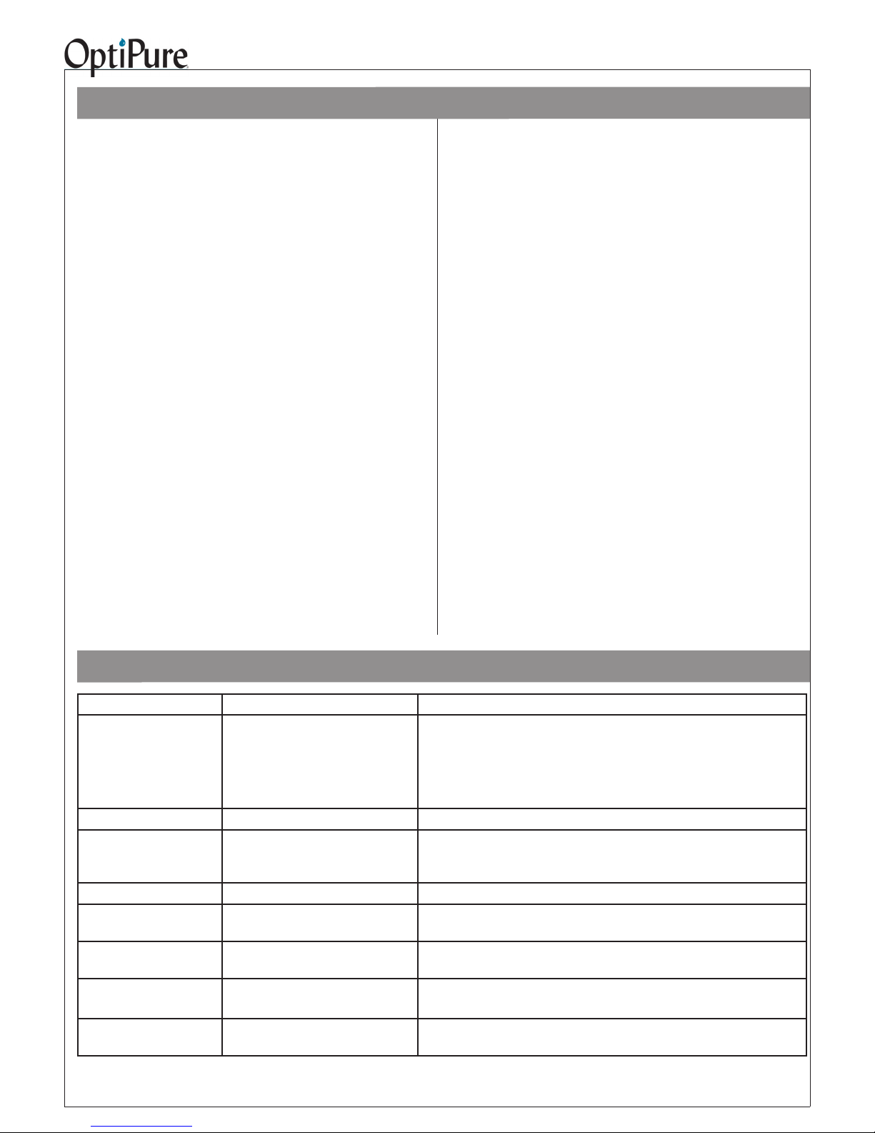
Trouble-Shooting
Problem Possible Cause Resolution
Running out of water. Operating Pressure reduced
Very cold Feed Water temperature
Low Feed Water Pressure
Demand exceeds system capacity
Poor water quality. Membrane failure Replace AMS-QT15 membrane
Short AMS-QT15 membrane life.
Short Pre-Filter life Heavy sediment loading Add FXAF01-12 or -12B for added Pre-Filter protection
Processor Does Not Shut
Off or Turn On
Water Quality Monitor will
not turn on
RP Pump runs intermittently or rough.
RP Pump cycles on-off
frequently
Poor Feed Water quality, presence of
iron, silica or non-calcium carbonate
hardness
Automatic Shutoff Valve not functioning
Dead batteries Replace batteries by sliding Water Quality Monitor up and removing the six
Air trapped in pump head.
Downstream water leak.
Low air pre-charge in Buffer Tank Empty Buffer Tank and re-charge air pressure to 20 psi.
Pre-Filters need to be replaced
Raise water temp to increase production or determine if higher capacity
system is required
Install optional Feed Water Pressure Booster Pump
Determine if the demand is unusual or consistent or resize system
Determine Feed Water quality by obtaining a water quality report from city
water supply utility or contact your OptiPure dealer
Replace Automatic Shutoff Valve
screws on the back cover. Remove cover to access battteries.
Unplug pump and open downstream valve to empty Buffer Tank.
Repair or eliminate downstream water leak.
OP175 System Installation, Operation & Maintenance 16
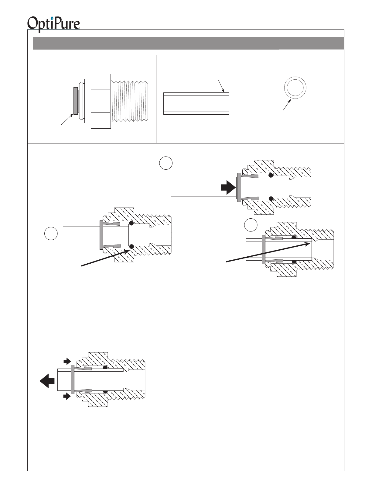
How to Use Our Push-to-Connect Fittings
Fitting Overview
Fitting Body
Collet/Gripper
(Dark Gray)
To Attach Tubing:
To ease insertion, moisten end of tubing with fresh
water or 3% hydrogen peroxide solution.
Push tubing straight in.
2
Resistance will be felt when the
tubing meets the O ring.
Tubing Preparation
The outside of the tubing must be
free of knicks and gouges.
Cutaway view of tting and tubing
1
Keep pushing until the
resistance is overcome
and the tubing rests
against the stop.
Cut tubing with a plastic tubing cutter or a
razor knife. Make a clean, square cut.
After cutting, make sure the end of the tube is
round. Correct any out of roundness that may have
occured in cutting the tubing.
Tube Stop
O-Ring
3
To Remove Tubing:
Press collet in to release grippers. While holding the collet
in, pull out on the tubing.
It may be necessary to use a partially open crescent wrench
or similar device to hold both sides of the collet in while
pulling the tubing out.
 Loading...