


BWS1500
Advanced Membrane
Separation System
Installation, Operation
& Maintenance Manual
Rev. 2.1
BWS1500-iom-manual_v2-1.indd
©2016 Procam Controls, Inc. All Rights Reserved
Manufactured By:
OptiPure Div. of
Procam Controls, Inc.
2605 Technology Drive, Bldg. 300
Plano, TX 75074
P: 972.881.9797 F: 972.422.6262
BWS1500 System Installation, Operation & Maintenance 2
General Information
Safety Warning
Electrical work should be performed by a qualied
electrician in accordance with all applicable
codes and regulations.
Service Contact
For local maintenance and service information
please contact your nearest Authorized Service
Representative. Service inquiries may be directed
to technical support at:
OptiPure div. of Procam Controls, Inc.
2605 Technology Dr. Bldg. 300
Plano, TX 75074 USA
Phone #: 972.881.9797
Fax #: 972.422.6262
E-mail correspondence to:
techsupport@optipure.net
Safety Instructions
1. Please read and follow these instructions
when connecting and using the system.
2. To avoid electrical shock, never touch the
inside of the electrical box. Only a qualied
technician should open the electrical box.
3. Never use the system if the power cord or
oat switch cable has been damaged. Do not
allow anything to rest on the power cord or
oat switch cable, and keep the cords away
from any place where people may trip over
them.
4. When disconnecting from the electric socket
hold the plug, not the cord.
5. If the processor does not function properly,
especially if there is an unusual sound or
smell coming from it, immediately unplug
the processor. Call your authorized service
representative.
Environmental Conditions
The BWS1500 is certied to operate under the
following conditions:
1. Altitude up to 2000 m.
2. Ambient temperature of 40-105°F (5 - 40°C).
3. Max relative humidity 80% at 88°F (31°C).
4. Main supply voltage not to exceed +/- 10%.
5. Installation category II.
6. Pollution degree II.
7. Indoor use only, protect from elements.
Explanation of Symbols
The following symbols are used on the water
processor. The symbols and their explanation is
given below:
Earth ground:
6. Unplug the processor and RP pump from the
AC outlet prior to any service.
7. Locate the RP Assembly as close as possible
to an AC outlet.
8. Securely bolt processor to wall before
operating.
9. Avoid cross-connections and install on cold
water supply only.
10. Use approved Air-Gaps when connecting to
drain lines.
11. Do not exceed system pressure rating and
use water hammer arrestors when water
hammer is evident.
12. Turn off Feed-Water supply before lter or
membrane cartridge replacement.
WARNING: Hazardous Voltage:
BWS1500 System Installation, Operation & Maintenance 3
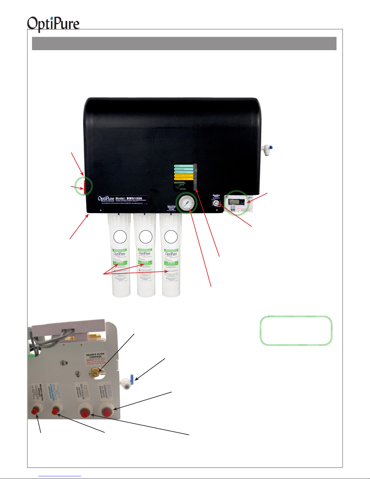
Getting To Know Your System
The BWS1500 Advanced Membrane Separation System is designed specically for users that desire the ability to customize the TDS (Total Dissolved Solids) level or “Mineral Content” of the treated water. The BWS1500
utilizes a precision multi-turn Blending Valve to accomplish this with great accuracy. This system design maxi-
mizes the ability to accurately blend a calculated percentage of the ltered water with the product water exiting
the Membrane, providing an Optimized Water to your equipment with the characteristics that you desire.
120VAC
Power Cord
(Coming from bottom rear of bracket)
- Plug in to standard
wall outlet.
Emergency
Bypass Valve -
User can switch from
Optimized Water to
Untreated Water
when needed, by turning handle horizontal.
Feed water
Inlet 3/8” Push-To-Connect -
Connect to Water Supply
Valve.
3@ CTO-Q
Pre-Filters
PN: 300-05830
1 2 3
Blending
Valve - Allows precise adjust-
ment of optimized water TDS
(mineral content).
System Status Display & Bypass Switch
- LEDs show state of system. Bypass Switch turns
Processor OFF when system is in Emergency
Bypass.
Operating Pressure Gauge
Shows feed pressure only when processor is
operating (when level in storage tank is low).
Water Quality Indicator -
Operates momentarily, push purple
button to turn on. Push “IN” button
for the TDS of the water going into
your equipment. Push “OUT” button
for the TDS of the puried water
from the membrane.
Underside of Processor:
Reject Water Outlet
- 1/4” Push-to-Connect
- Connect to drain per local
regulations.
Optimized Water Outlet
- 3/8” Push-To-Connect
- Connect to Optimized Water Storage
Tank Inlet
Reject Flow Control Valve
NOTE: Never close Reject Flow Control Valve nor
limit Reject ow to less than Permeate ow!
Sample Port
- 3/8” Push-to-Connect - Used to ush pre
lters, gather a water sample, measure pro-
duction, or drain water from storage tank.
Pressurized
Optimized Water to Equipment Outlet
- 1/2” gray hose
- Connect to End User Equipment
Storage Tank/RP Return Line
-1/2” gray hose
- Connect to Repressurization Assembly Outlet
Normal
Operation
Items in green circles show a nor-
mal operating condition/position.
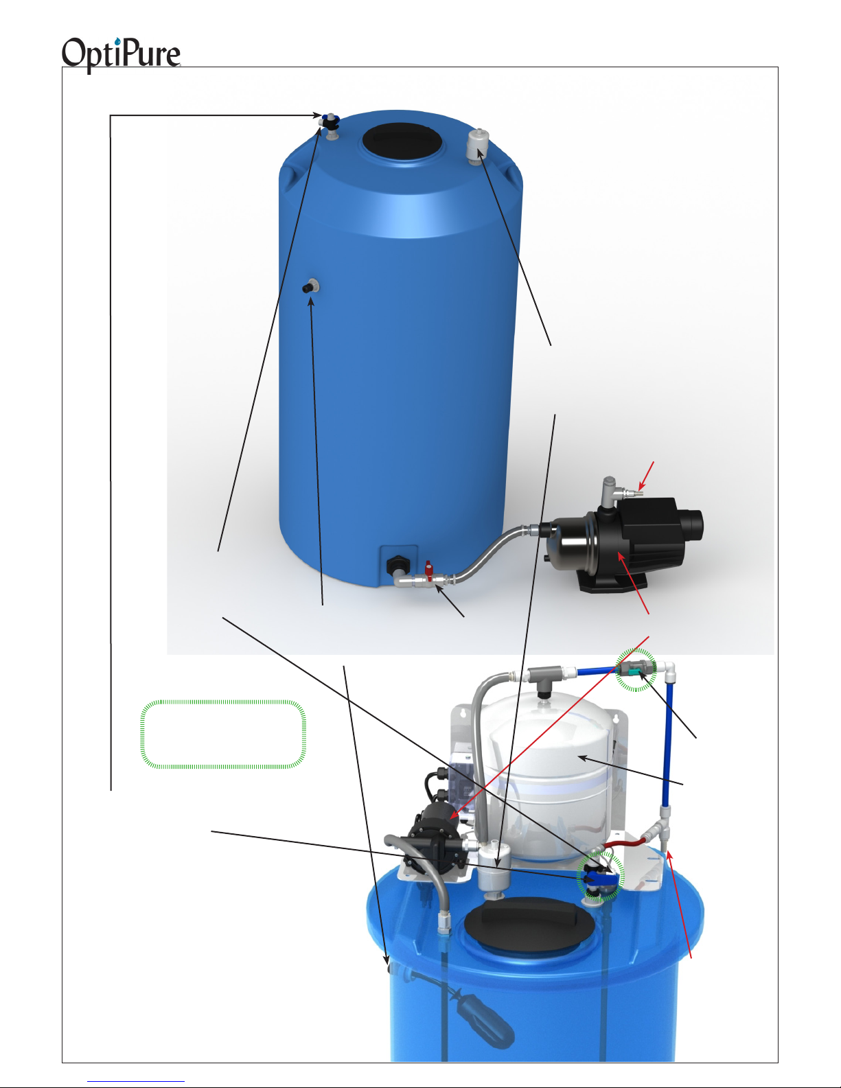
BWS1500 System Installation, Operation & Maintenance 4
175 Gallon
Optimized Water
Storage Tank
with Separate RP
Pump
Absolute 0.2
micron
Hydrophobic
Air-Breather/
Filter
RP Pump Outlet
- Connect to Storage
Tank/RP Return Line connection on Processor
Optimized Water to
Storage Tank Inlet - 3/8”
Push-to-Connect - Connect
to Optimized Water Outlet on
Processor.
Items in green circles show a nor-
mal operating condition/position.
Tank Inlet Divert Valve
- Normally in Down position.
Turn handle to Up position
to divert Optimized water to
sample port.
High Level Float Switch
Cable
- Connect to Processor “Tank
Electrical Connection.”
Normal
Operation
50 Gallon
Optimized Water
Storage Tank/RP
Pump Assembly
Tank Outlet
Valve
Repressurization
Pump
120VAC - Plug in to
standard wall outlet.
Buffer Tank
Valve
- Shown in
normal position
Buffer Tank
- Pre-charged air
bladder - 20 psi
Repressurization Assembly
Outlet
- 1/2” Hose Barb Connect to Storage
Tank/RP Return
Line connection on
Processor

BWS1500 System Installation, Operation & Maintenance 5
Installation Requirements
This section and the next provide the water, electrical
and space requirements for the BWS1500. Pay
special attention to the feed-water chemistry
requirements. Operating a system on water supplies
outside of these parameters may lead to premature
membrane failure. This product is for commercial
use only and must be installed and maintained in
accordance with manufacturer’s guidelines and local
regulatory plumbing and electrical codes.
Operating parameters
Typical Membrane TDS* rejection:
97+%
Feed Temperature: 40 - 100° F (4 - 38° C)
Feed pressure: 50 - 80 psi
(3.4 - 5.9 bar) at 3 gpm
Production** (at 77°F, 60 psi)
1500 gals/day,
62.5 gals/hr, 1.0 gpm
Recovery: up to 40%.
IMPORTANT NOTE: The nominal production rate
is strictly dependent on feed water temperature
and pressure. Reduced temperature or
pressure will reduce production. For example:
Operating pressure of 30 psi will cut production
by 50%. 48˚F feedwater will cut production by
50%.
Location
The system should be installed indoors, in the
proximity of the equipment (within 25 feet) and
protected from the elements. Do not let the processor
or storage tank freeze or be exposed to rain or direct
sunlight.
Post-treatment
Treated water stored in a tank may absorb organic
compounds from the tank, which can affect water
taste and odor. If product water is for consumption, an
optional post-treatment lter, such as an OptiPure
FX or QT carbon lter, should be installed after the
tank. If used, it is best installed as close to the point of
use as possible. Other specialized post-treatment is
also available.
Feed water connection
An adequate ow and pressure of water to the unit is
essential for successful operation. Provide a dedicated
3/4” water line to the vicinity of the installation. Install
a full-ow ball valve and pressure gauge with 3/4”
female pipe thread (user supplied) for connection to
installation hardware provided with the system. A 1/2”
male pipe thread x 1/2” push-to-connect adapter is
included in the installation kit.
*TDS (total dissolved solids) create conductivity in water and are
expressed in ppm or mg/l (parts per million or milligram per liter).
System Reject % depends on blended water setting.
**Nominal production @ 77°F (25°C) @ 500 ppm based on a 24 hr
day. Actual production will vary based on variations in blend setting,
water temperature, pressure, and TDS.
Drain
A drain should be located within 5 feet of the location
of the unit. Drain must allow a minimum ow of 5
gallons per minute. Compliance with most local
plumbing codes requires installation of an approved air
gap in the drain line. The drain connection should be
accessible for system set-up and service.
Electrical requirements
A power source with two outlets should be located
within 5 feet of the location of the unit.
Processor 120V, 60Hz 6 Amps
RP Pump 120V 60Hz 8 Amps
Feed-water chemistry
Feed TDS Up to 1200 ppm
Feed pH 6 - 10
Hardness 28 grains or less
Free chlorine <2 mg/l
Iron (Fe) 0.1 mg/l max.
Turbidity <0.05 NTU
Manganese 0.05 mg/l max.
Hydrogen sulde 0.0 mg/l
A water analysis must be conducted before installing
the system, or the information requested above can
be obtained from your local water utility. If your water
analysis shows that any of these parameters are not
within range, additional pretreatment and/or higher
frequency of maintenance may be required. Contact
your OptiPure distributor for assistance. The presence
of silica or occulants such as alum or cationic
polymers in the feedwater may cause membrane
fouling and may require special chemical pretreatment
or periodic membrane cleaning. Please note that
membrane failure due to fouling is not covered by the
warranty.
Storage Tank/RP Pump
The tank must be located within 10 feet of the water
processor unit. The oor beneath the storage tank
should be smooth, clean and free of sharp objects that
could puncture the bottom of the tank. Note: The tank
is atmospheric, with a sub-micron, hydrophobic air
breather lter.
For a 175 Gallon Tank, the separate RP Pump must
be placed next to the tank at a height even with the
bottom of the tank, or on a stand no more than 6”
above the bottom of the tank.
Optimized Water Lines to Equipment
Tubing, piping and associated ttings connecting
Optimized water lines to equipment shoud be food
grade material that meets NSF Std 51 or 61 with a
minimum pressure rating of 75 PSI. Optimized water
may react with most metal piping imparting a bad
taste. Plastic pipe or reinforced opaque beverage
tubing are acceptable choices for Optimized water
distribution. The larger inside diameter tubing or hose,
the better to minimize pressure drop.
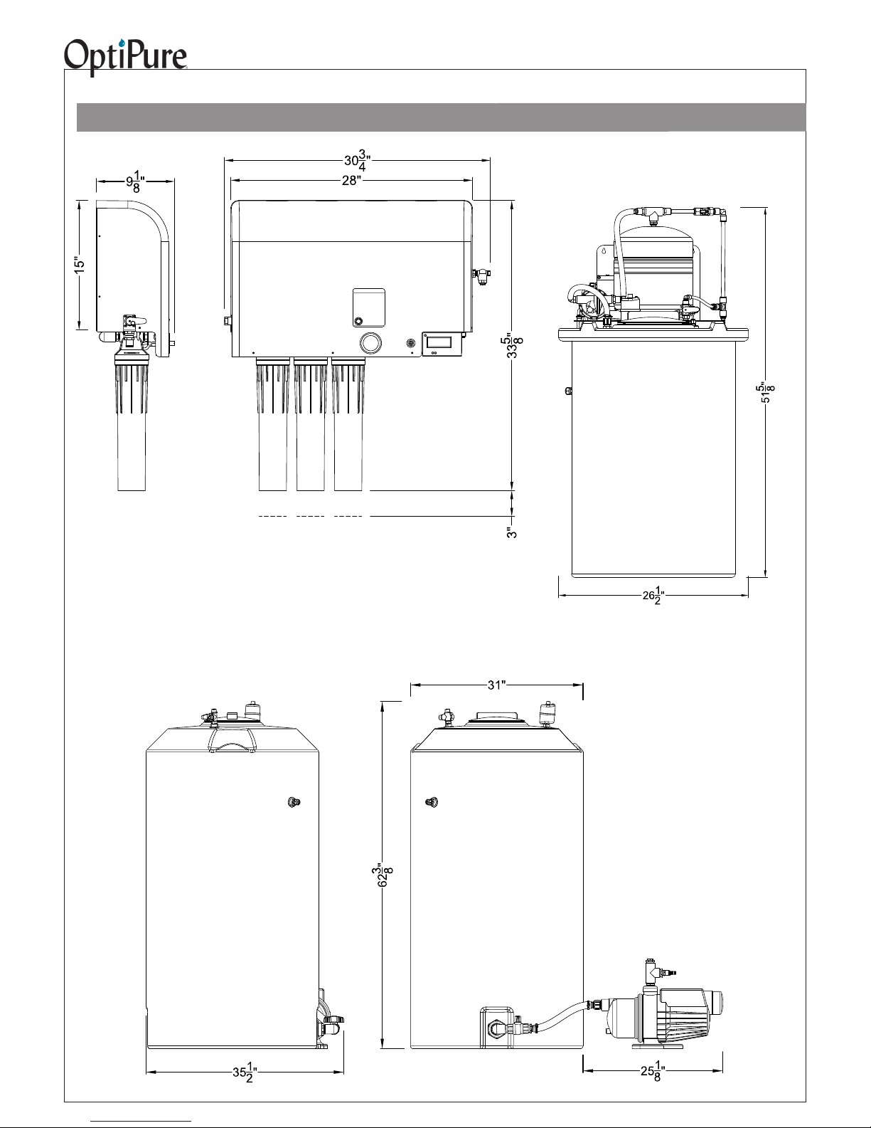
BWS1500 System Installation, Operation & Maintenance 6
Equipment Dimensions
50 Gallon Tank
Repressurization Assembly
Processor
Left Side
Processor
Front View
View
IMPORTANT - ALLOW A MINIMUM OF 24” IN FRONT OF THE PROCESSOR FOR
MAINTENANCE AND SERVICE. DO NOT MOUNT SYSTEM ABOVE THE CEILING
OR IN A LOCATION THAT IS NOT EASILY ACCESSIBLE. WHEN THE 50 GAL. TANK
ASSEMBLY IS FULL OF OPTIMIZED WATER IT WILL WEIGH 450 LBS (THE 175 GAL.
TANK, 1500 LBS). ALWAYS LOCATE THE STORAGE TANK WHERE IT CAN BE ACCESSED DURING SERVICE.
Allow 3”
to remove
cartridges
175 Gallon Tank
with Repressurization
Pump
BWS1500 System Installation, Operation & Maintenance 7
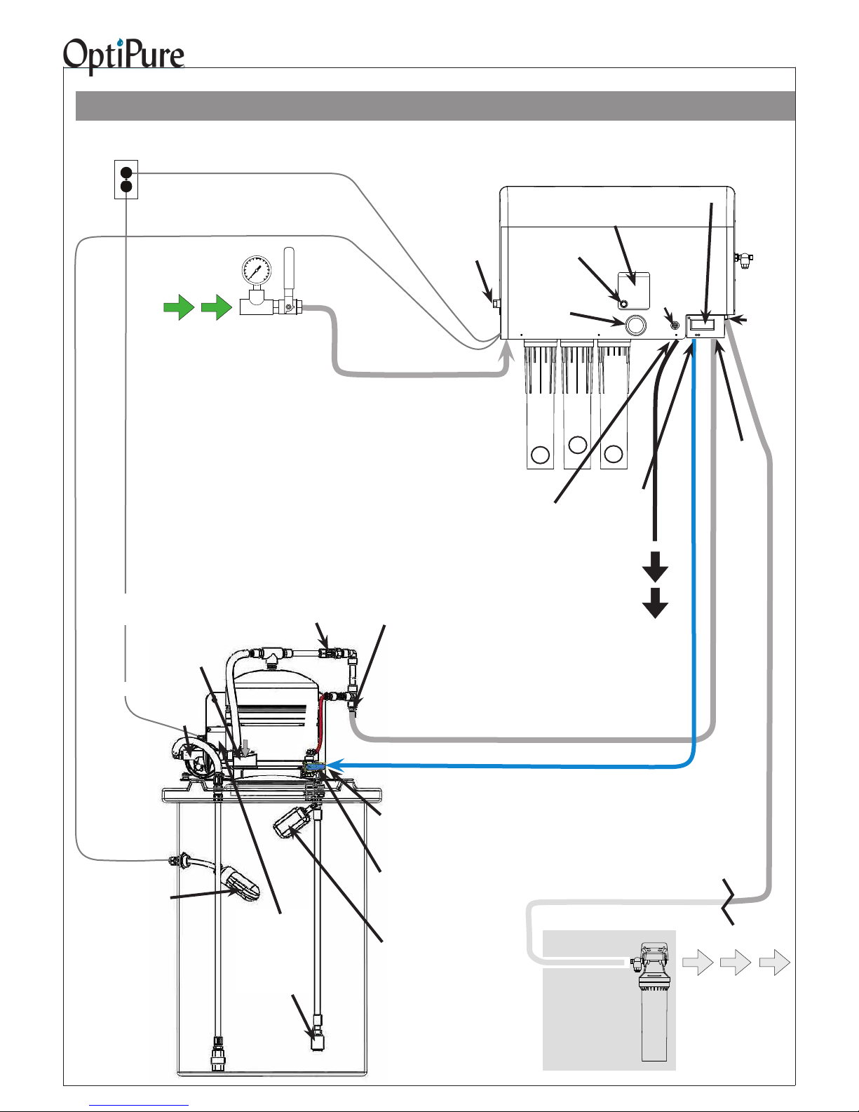
Typical Installation with 50 Gal. Atmospheric Tank
Important: Plumbing should be performed by a qualied plumber in accordance with local codes.
Power
120VAC, 2A
Tank High Level Float Switch Cable
Feed
Water
When installing, keep lines from the Processor to
the equipment as short as possible to minimize
pressure loss.
IMPORTANT - PROTECT PROCESSOR AND
TANK/RP PUMP FROM THE ELEMENTS. DO NOT
INSTALL IN DIRECT SUNLIGHT OR WHERE EXPOSED TO FREEZING TEMPERATURES OR RAIN.
Repressurization
Assembly
Power Cord
User-Supplied
Water Supply
Valve &
Pressure Gauge
Buffer Tank Valve
(Normally Open)
Emergency
Bypass Valve
Feed Water Line
- 1/2” Gray Hose with hose barb
inserts at both ends - from Water
Supply Valve to Feed Water Inlet
Repressurization
Assembly Outlet
(Hose Barb)
Processor
Operating
Pressure
Gauge
Feed
Water
Inlet
CTO-Q
1
Reject
Water
Outlet
Bypass
Switch
CTO-Q
Pre-Filter
2
(to Drain)
System
Status
CTO-Q
Pre-Filter
3
Optimized
Water
Outlet
Reject
Water
Water Quality
Monitor
Blending
Valve
-Set to
req'd
TDS
reading!
Pre-Filter
Sample
Port
Optimized
Water
to Eqpt
Storage
Tank/RP
Return
Drain Line - Black -
from Reject Outlet to Drain
Repressurization
120VAC
Processor
Control High
Level Float
Switch
(inside tank)
Air
Breather
Pump
Buffer
Tank
Low Level
Float Switch
(inside tank, with
Control Box attached to Buffer
Tank bracket)
Bypass
Pressurized Water Line
- 1/2" Gray Hose with hose barb inserts at both ends - from
Repressurization Assy Outlet to Storage Tank/RP Return
Optimized Water Line
Optimized
Water to
Storage Tank
Inlet (on valve)
Tank Inlet Divert Valve
(Valve normally in Down
position. Turn to Up position
to bypass Repressurization
Assy.)
Safety Float
Valve
(inside tank)
- Blue - from Optimized Water Outlet to Tank Inlet
Optional
Optimized Water
Storage Tank
- 50 gal. Atmospheric
Carbon
PostTreatment
Optimized Water Line - 1/2" Gray Hose
with hose barb insert - Make connection to
distribution and (optional) post-treatment.
Optimized
(Treated)
Water to
Equipment
BWS1500 System Installation, Operation & Maintenance 8
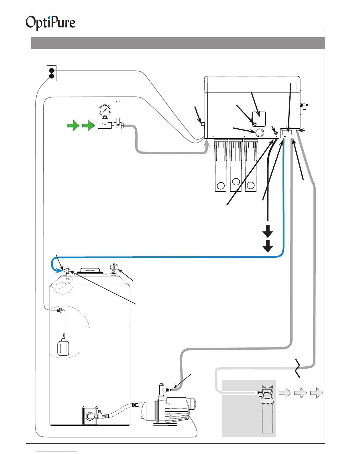
Typical Installation with 175 Gal. Atmospheric Tank
Important: Plumbing should be performed by a qualied plumber in accordance with local codes.
Power Cord
When installing, keep lines from the Processor to the
Equipment as short as possible to minimize pressure loss.
IMPORTANT - PROTECT PROCESSOR AND TANK/RP PUMP
FROM THE ELEMENTS. DO NOT INSTALL IN DIRECT
SUNLIGHT OR WHERE EXPOSED TO FREEZING TEMPERATURES OR RAIN.
Storage Tank/
Repressurization Pump
Optimized Water to
Storage Tank Inlet (on valve)
Power
120VAC, 2A
Feed
Water
Power Cord
High Level Switch Cable
User-Supplied
Water Supply
Valve &
Pressure Gauge
Emergency
Bypass Valve
Feed Water Line
- 1/2” Gray Hose with hose barb
inserts at both ends - from Water
Supply Valve to Feed Water Inlet
Processor
Operating
Pressure
Gauge
Feed
Water
Inlet
CTO-Q
1
Reject
Water
Outlet
Bypass
Switch
CTO-Q
Pre-Filter
2
(to Drain)
System
Status
CTO-Q
Pre-Filter
3
Optimized
Water
Outlet
Reject
Water
Water Quality
Monitor
Blending
Valve
-Set to
req'd
TDS
reading!
Pre-Filter
Sample
Port
Optimized
Water
to Eqpt
Storage
Tank/RP
Return
Drain Line - Black -
from Reject Outlet to Drain
Safety Float Valve
(inside tank)
Processor Control
High Level Float
Switch
(inside tank)
Optimized Water
Storage Tank
- 175 gal. Atmospheric
Tank Outlet
Valve
Optimized Water Line
- Blue - from Optimized Water Outlet to Tank Inlet
Air
Breather
Tank Inlet Divert Valve
(Valve normally in Down
position. Turn to Up position to
measure water production.)
Pressurized Water Line
- 1/2" Gray Hose with hose barb inserts at both ends - from
Repressurization Assy Outlet to Storage Tank/RP Return
Repressurization
Pump
120VAC
RP Outlet
Optional
Carbon
PostTreatment
Optimized Water Line - 1/2" Gray Hose
with hose barb insert - Make connection to
distribution and (optional) post-treatment.
Optimized
(Treated)
Water to
Equipment

BWS1500 System Installation, Operation & Maintenance 9
Outside edge of
processor bracket
Plywood anchored to wall
11”
26.5”
27.75”
Wall Mounting
Before beginning installation of the system, remove the
plastic cover from the BWS1500 processor. Replace
cover at the end when installation and adjustments are
complete.
The processor should always be mounted where it is wellsupported, either using anchors in a cement wall, or using
the support of studs in a wall-board wall. Never mount it
directly to sheet-rock alone. Instead, mount it on a sheet
of plywood which is anchored to the wall studs, as shown
above.
Four user-supplied bolts or screws with a head diameter
between 3/8” and 1/2” (which will t into the keyholes in the
system bracket, but will not slip out when tightened) should
be used to hang the system. This will allow the unit to be
lifted off the bolts, if necessary for maintenance, without
removing all the bolts from the wall.
Mark the mounting screw locations with dimensions as
shown above. BE SURE TO ALLOW 3” BELOW THE
CARTRIDGES TO ALLOW FOR REMOVAL. Screw the
four bolts or screws in place, leaving approximately 1/4”
clearance between the bottom of each screw head and the
wall. Position the system over the mounting screws, and let
the bracket slip down into the keyholes. Tighten the screws.
Tighten all screws.
System Installation
Note: Do not plug in the power cord from the RP pump
until completing the section “System Start-Up”.
Refer to “Typical Installation” diagram on pages 7 & 8,
and “How to Use Our Quick-Connect Fittings” on the
last page of this manual, when making the following
connections.
A feed water ball valve and pressure gauge (user supplied)
should be installed to provide water to the system FEED
WATER INLET with the 1/2” gray hose (supplied). Hose,
tubing and ttings for making connections between the
processor, storage tank and drain are supplied in the
installation kit. Hose and tubing will need to be cut to
appropriate lengths.
1. Remove the tank lid. Inside the tank, the oat
valve may be secured for shipping. Remove any
wrapping on the oat to allow it to hang and move
freely.
2. DRAIN: Connect the 3/8” black tubing from the
installation kit to the REJECT WATER OUTLET on
the processor. Run the line to an appropriate drain.
15”
4. PROCESSOR TO TANK: Connect a piece of the
NOTE: When cutting the tubing, use a sharp tubing
cutter or blade and make a clean, straight cut before
inserting into a push-connect tting. When routing
tubing, do not make sharp bends or crimp the tubing.
5. TANK/RP PUMP - 175 Gallon Storage Tank Only:
6. TANK/RP PUMP TO PROCESSOR: Using two of the
7. HIGH LEVEL SWITCH CABLE: Route the cable coming
Observe local plumbing codes and supply an
appropriate air gap. (Any ttings for connecting to
the drain will need to be supplied by the customer.)
Fix tubing in place at the drain.
3. FEED WATER: Apply 3 wraps of Teon tape to the
1/2” FPT x 1/2” push-connect tting (supplied).
Screw the tting into the Feed Water Supply Ball
Valve and tighten (DO NOT OVERTIGHTEN).
Insert one of the supplied 1/2” Hose Insert x 1/2”
Tube Stem ttings into the 1/2” gray hose and
secure it with a hose clamp. (See “Hose Fitting
Assembly” photo.) Insert this tting into the pushconnect tting at the Feed Water Supply. Route
the hose to the Processor and cut to appropriate
length. Using another Hose Insert x Tube Stem
tting, connect the other end of the hose to the
FEED WATER INLET located on the Bypass Valve
on the left side of the Processor.
3/8” blue tubing to the OPTIMIZED WATER OUTLET
tting on the Processor. Connect the other end of this
tubing to the OPTIMIZED WATER INLET on the INLET
DIVERT VALVE (see photo) at the top of the Storage
Tank.
Place the pump near the storage tank, on the oor or
on a stand no more than 6” above the bottom of the
tank, with the pump inlet towards the tank. Using the
supplied 1” hose and large hose clamps, connect the
tank outlet hose barb to the pump inlet hose barb.
1/2” hose barb inserts (supplied), a piece of 1/2” gray
hose, and two hose clamps, connect hose from the
REPRESSURIZATION ASSEMBLY OUTLET on the
50 Gallon Repressurization Assembly - for the 175
Gallon Tank, the push-connect tting in the tee on top
of the RP Pump - to the STORAGE TANK/RP RETURN
LINE connection on the Processor.
from the high level switch through the hole in the rear
Hose Fitting Assembly

50 Gallon Storage Tank Connections
BWS1500 System Installation, Operation & Maintenance 10
Repressurization Assy
Outlet
Tank Inlet
Divert ValveShown in the
normal positon
Optimized
Water Inlet
Route cable from high
level switch from below,
up through the same hole
that the power cord passes
through (left rear of Processor metal bracket).
Tank Inlet
Divert ValveShown in the
normal positon
Optimized
Water Inlet
175 Gallon Storage Tank Inlet
Connecting 175 Gallon Storage Tank & RP Pump
left of the Processor bracket, to the electrical control
box on the Processor. Connect the AMP connector to
the HIGH LEVEL SWITCH connector located on the left
side of the box. (See photos.)
8. OPTIMIZED WATER TO EQUIPMENT: Connect a piece
of 1/2” ID gray hose to the OPTIMIZED WATER TO
EQUIPMENT outlet on the Processor with a 1/2” hose
barb insert and clamp (supplied). At a later time, the
other end of this line will be connected to the distribution
line that will deliver Optimized Water to the equipment,
but for now leave the line loose and route the loose end
of the gray hose into a drain or bucket. (Make certain
the hose length will reach the storage tank; this will
be required for the Start-Up procedure.) Prepare any
necessary plumbing to make the connection between
the 1/2” hose and the distribution line, which will be
completed in “Connect to Equipment”.
NOTE: If Post Filtration is used, it will be installed between
Routing High Level Switch Cable
Plug high level
switch cable into
connector on control
box.
High Level Switch Cable Connection
the Optimized Water Outlet and the designated equipment.
Install QT Cartridges
NOTE: Before installing the QT Cartridges make sure to
remove the plugs in the QT heads on the Processor.
Insert the CTO-Q cartridges into QT heads 1, 2 & 3 (starting
from the left side of the Processor) and turn to align arrows.
1 2 3

BWS1500 System Installation, Operation & Maintenance 11
Optional RP Assembly Location
For the 50 Gallon Tank only, the Repressurization Pump
and Buffer Tank assembly is on a stand that can be remote
from the storage tank. If this type of installation is required,
the RP Assembly should be built as a remote unit from the
OptiPure, with additional installation instructions supplied.
System Start-Up
Refer to illustrations “Typical Installation” (pages 7 & 8) and
“Switch Testing” (last page of this manual).
IMPORTANT: Before proceeding, position the Processor
EMERGENCY BYPASS VALVE in the “SERVICE” position,
and position the TANK INLET DIVERT VALVE in the down
position (Blue Valve Handle pointing sideways). For a 50
Gallon Tank, assure that the BUFFER TANK VALVE is
open. For a 175 Gallon Tank, ensure that the tank outlet
valve at the bottom of the tank is open (handle parallel to the
valve body).
1. Open the WATER SUPPLY VALVE. Plug the processor
power cord into a 120VAC outlet. Allow the lter
housings to ll, and then the pump will turn on. (Water
will ow into the tank and from the end of the 3/8” black
tubing routed to the drain. Allow several minutes to
ush the system until water ows smoothly into the tank
and also from the drain line. Check all of the plumbing
connections and correct any leaks if necessary.
2. Test the high level oat switch. With the tank lid
removed and the system running, raise and tilt the
processor control oat (in the tank). As you raise the
oat upward, the ball inside the oat will roll from one
end of the oat to the other, activating the switch.
• With the oat in the upright position, the water
processor should shut off the water ow. The pump
should turn off and there should be an LED light
indicating “Tank Full” on the control box.
• Lower the oat allowing the ball to drop back down.
The water should begin owing again after a delay.
3. The Storage Tank must have about 14 gallons in it to
start-up and purge the Repressurization Assembly. You
can quickly ll the storage tank to the appropriate
level using the “System Bypass” on the processor.
To do this:
• Route the 1/2” gray hose from the processor
OPTIMIZED WATER TO EQUIPMENT outlet directly
into the storage tank lid opening.
NOTE: Before performing the next step, be certain to
rmly grip the gray hose.
• Turn the EMERGENCY BYPASS VALVE on the
processor to the “BYPASS” position. This will allow
feed water to bypass the processor and quickly ll the
storage tank.
• When the tank lls approximately 14 gallons
(1/3 full with the 50 gal. tank, or 2 feet of water
in the 175 gal. tank), return the PROCESSOR
EMERGENCY BYPASS VALVE to the “SERVICE”
position.
NOTE: Before performing the next step, be certain to
rmly grip the gray hose.
4. Plug the power cord from the RP pump into the outlet.
For a 175 Gallon Tank, turn on the RP Pump (button
on top of pump). Water should begin to ow rapidly from
the Storage Tank to the Processor and back into the
Storage Tank through the gray hose. Allow the pump
to recirculate the water for several minutes until all the
air is purged from the Repressurization Assembly (50
Gallon Tank), or from the RP Pump (175 Gallon Tank).
As the air is purged, the pump will begin to run more
smoothly and the water owing from the gray hose will
become steady.
5. Unplug the RP Pump cord.
Connect to Equipment
Refer to the illustration “Typical Installation” on pages 7 & 8.
1. Remove the 1/2” gray hose that was routed into the
storage tank (from the Optimized Water Outlet at the
Processor) and make the connection to the distribution
line that delivers Optimized Water to post-treatment (if
used) and to designated equipment.
2. Ensure that any manual or automated valves on the
connected equipment are closed. Plug the RP Pump
power back in (and turn it on if a 175 Gallon Tank). The
pump will run and build pressure (on a 50 Gallon Tank,
it will ll the Buffer Tank until the pressure in the Buffer
Tank reaches 70 psi), and then the RP Pump will shut
off.
3. Open downstream valves at the equipment to allow
water to ow and air to purge through the post-treatment
(if used) and from the distribution lines. When purging
distribution lines do not allow the water level in the
storage tank to drop below the bottom outlet tting
(on 175 Gallon Tank). On a 50 Gallon Tank, the pump
will shut off automatically if the water level drops
too low. (Add more water to the tank if necessary.)
Once distribution lines are ushed and all air is purged,
close the equipment valves. When there is no demand
for water the RP Pump will shut off automatically.
4. Before proceeding, follow these steps to empty the
storage tank of untreated feed water:
• Connect a piece of 3/8” blue tubing into the push-to-
connect tting of the SAMPLE PORT VALVE on the
right side of the processor, and route the other end of
the tubing into a drain or bucket.
• Open the Sample Port Valve to drain water from the
storage tank. When the pump begins to suck air (or,
with a 50G tank, it shuts off), close the Sample Port
Valve.
5. Replace and tighten the lid onto the storage tank.
System Blend Adjustment
IMPORTANT: The TDS Blend must be properly adjusted
before operating the connected equipment. If you do
not know the “TARGET TDS” SET THE BLEND “IN”
between 60 and 80. The owner/operator should consult
with their OptiPure Dealer or contact the OptiPure factory for
assistance in determining an appropriate TDS Target Range.
An improper TDS Blend setting or failure to properly
maintain the system can cause damage to equipment.
Factors that can impact the TDS of the Optimized Water
include changes in water pressure and temperature,

BWS1500 System Installation, Operation & Maintenance 12
seasonal changes in water quality, and municipal source
blending practices. To assure maintaining your target TDS
range year-round we recommend periodically checking the
“IN” TDS and making adjustments as needed.
Optimized Water TDS - Blending Adjustment
1. Allow the system to operate for at least 5 minutes before
continuing to Step 2.
2. Push the purple “POWER” button on the Water
Quality Monitor located on the upper left corner. It will
immediately display the “IN” or Optimized Water - TDS
(Total Dissolved Solids) in PPM (parts per million). By
adjusting the blend valve you are able to change the
“IN” TDS to the desired Target Range.
3. Within 30 seconds, push the “OUT” button to display the
Permeate Water TDS (from the RO membrane).
4. If the “IN” TDS is outside of the desired range:
• Turn the Blending Valve knob counter-clockwise to
open the Blending Valve, increasing the amount of
Filtered Water blending with the RO water, thereby
increasing the TDS of the Optimized Water.
• Turn the Blending Valve know clockwise to close the
Blending Valve, decreasing the amount of Filtered
Water blending with the RO water, thereby decreasing
the TDS of the Optimized Water.
5. Once the desired TDS is obtained allow the system
to run for several minutes, periodically checking the
“IN” TDS. Make smaller incremental adjustments as
necessary until the TDS “Target” is achieved.
Complete the Installation
Transition to Owner/Operator
The FINAL STEP is to meet with the Owner/Operator,
familiarize them with the system and complete the Post-
Installation Check List.
The system is now in “normal operating” mode and
the storage tank will ll with Optimized Water from the
Processor. Complete the “Post Installation Checklist” to
Conrm Normal Operation and System Settings.
Allow the storage tank to ll before beginning operation
of the connected equipment.
Emergency Bypass Operation
The System Bypass is used for any interruption of Optimized
Water ow (such as lter change or component failure), to
bypass the processor and RP assembly and allow ow of
tap water to the equipment. To place the system in Bypass
mode, place the Bypass Switch on the Controller in the
“System Disable” position to turn off the Processor Pump.
Unplug or turn off the RP Pump. Turn the Emergency Bypass
Valve on the Processor to the “System Bypass” position.
When normal operation is restored, toggle the Bypass
Switch, plug in/turn on the RP Pump, and turn the Bypass
Valve to the “Service” position.
What are all those parts and what do they do?
This section will give you an overview of how the
system works. Refer to diagram on following page.
• Incoming water is ltered by the prelters (1), which
remove sediment, chlorine and organics.
• When the Emergency Bypass Valve (2) is in the normal
SERVICE mode, water ows through the Processor.
When the Bypass Valve (2) is in System Bypass mode,
the water is diverted directly out to the equipment,
bypassing both the Processor and the Tank/RP Pump.
• When water in the Storage Tank (3) is at a low storage
level, the High Level Float Switch (4) drops, causing the
Switch to close, causing the Solenoid Valve (5) in the
Processor to open and allowing ltered water to ow
through the Processor. The Pressure Switch (6) closes
when there is sufcient water pressure to operate the
system, allowing the Pump (7) to operate, pressurizing
the water owing to the Membrane (8). The Membrane
feed water pressure is indicated by the Operating
Pressure Gauge (9). Some ltered water is also diverted
away through the Blending Valve (10).
• The water owing to the Membrane (8) is split by the
Membrane into a pure water stream (“permeate”) and
a reject water stream. The Pressure Regulator Valve
(11) allows some of the reject water to recirculate back
to the Pump (7). The rest of the reject water, controlled
by the Reject Flow Control Valve (12), ows out to the
drain. Recirculating a portion of the reject water causes
a higher ow velocity through the Membrane, serving to
clean the Membrane surface and increase Membrane
life.
• The pure water stream from the Membrane continues
through the Permeate Check Valve (13), blends with the
metered ltered water from the Blending Valve (10) to
create an Optimized water stream which then goes on to
the Storage Tank (3) through the Tank Inlet Divert Valve
(14) on top of the Tank. Air in the tank is displaced by
the incoming water and vented out of the Sub-Micron Air
Breather (15).
• When the tank completely lls, the High Level Float
Switch (4) rises, causing the switch to open, causing the
Solenoid Valve (5) to close, stopping the ow through
the Processor.
• When the “IN” button is actuated on the Water Quality
Monitor (16), it measures the TDS of the Optimized
Water in the Optimized Water Line going to the storage
tank. When the “OUT” button is actuated, the Water
Quality Monitor (16) indicates the TDS of the pure water

BWS1500 System Installation, Operation & Maintenance 13
Feed
Processor
2
21
To User
Equipment
16
9
5
1
8
11
6
7
12
10
13
18
19
17
22
23
14
4
24
20
15
3
stream exiting the Membrane (8). The Water Quality
Monitor is battery powered with two AA batteries. It will
automatically shut-off after 30 seconds.
• As long as the Low Level Float Switch (24)
detects a minimum level of water in the Tank, the
Repressurization (“RP”) Pump (17) is enabled to draw
from the Atmospheric Storage Tank (3) and dispense
Optimized water by way of the Buffer Tank (19 - on a
50 Gallon Tank only) through the Processor and the
Pressurized Water Check Valve (18). (Note that, due
to the design of the RP Pump used with the 175 Gallon
Tank, no Buffer Tank and no Low Level Float Switch are
needed.) When the pressure drops in the Buffer Tank
(with 50 G Tank) or downstream (with 175 G Tank), the
RP Pump runs until pressure is restored, then shuts off.
• The Optional Post-Treatment Filter (20) is designed
to provide additional treatment based upon specic
application requirements. For beverage applications an
activated carbon lter is recommended.
• As Optimized Water is dispensed from the storage tank
by the Repressurization Pump (17), air is replaced
in the tank through the Sub-Micron (0.2 micron) Air
Breather (15).
• If the RP Pump (17) fails, water ow can be restored to
the equipment by turning the Emergency Bypass Valve
(2) to the “SYSTEM BYPASS” position. (The Bypass
Switch on the Controller must also be placed in the
“System Disable” position.) This allows tap water to
bypass the processor and RP assembly.
To Drain
• A Sample Port (21) allows sampling and draining of
Optimized Water from the Tank (drain by closing the
Feed Water Valve or unplugging the Processor to stop
lling of the Tank, and opening Sample Port) .
• The Tank Inlet Divert Valve (14) and/or Sample Port (21)
additionally provide(s) the ability to measure membrane
production. With a 175 Gallon Tank/RP Pump, this is
done by turning the Tank Inlet Divert Valve (14) to the
bypass or UP position and sampling at the Tank Inlet
Divert Valve. With a 50 Gallon Tank/Repressurization
Assy, this is done by closing the Buffer Tank Valve (22),
turning the Tank Inlet Divert Valve (14) to the bypass
or UP position and opening the Sample Port (21). This
diverts the permeate through the Bypass Check Valve
(23) and back to the Sample Port (21) at the Processor
where permeate can be sampled. Note that on a 175
Gallon Tank/RP Pump, there is neither a Buffer Tank
Valve (22) nor Bypass Check Valve (23). Instead, there
is a Tank Outlet Valve at the bottom of the Tank.
Repressurization Pump Details
50 Gallon Tank
The Repressurization Assembly with a 50 Gallon Storage
Tank includes a diaphragm pump controlled by an internal
Pressure Switch, and a Buffer Tank between the Pump and
the downstream equipment maintains downstream pressure. Water demand for downstream equipment is directly
supplied from the Buffer Tank, and deman can go on and

BWS1500 System Installation, Operation & Maintenance 14
off as necessary. The RP Pump is not directly affected by
downstream demand, and downstream equipment is also
not affected by the automatic starting or stopping of the RP
Pump. When the pressure drops sufciently in the Buffer
Tank, the Pump starts automatically and repressurizes the
Buffer Tank. The operating pressure for the Buffer Tank is
preset (to 70 psi) and is NOT eld adjustable. The pump
also incorporates check valves to keep the Buffer Tank and
downstream line pressurized. The pump is equipped with
auto-reset, thermal overload protection and is designed for
intermittent duty.
If the pump runs erratically, allow the pump to run to
open drain with valve fully open to purge air from the
pump head. Disconnect the power and reconnect several times to facilitate air purging.
The pump will prime only if all the pressure is relieved from
the outlet port. The pump is self-priming up to 11 ft. The
pump can run dry but will overheat and the pump overload
will shut the pump off.
175 Gallon Tank
The Repressurization Pump with a 175 Gallon Storage Tank
is a demand-controlled pump that maintains pressure downstream at all times. It shuts off automatically when there is no
demand for water.
Storage Tank Level Controls
(See also the Electrical Schematic at the end of this manual.)
When the Storage Tank becomes full, the High Level Float
Switch shuts off the Processor, preventing ow to the Tank.
50 Gallon Tank Low Level Control
For a 50 G Tank, if the tank is
empty, the Low Level Float Switch
automatically shuts off the RP
Pump. As long as the power cord
from the Tank/RP unit is plugged
in, and there is a minimal amount
of water in the Storage Tank, the
green light is illuminated on the
Control Box (attached to the Buffer
Tank bracket), indicating that power
is supplied to the RP Pump. This
light means the RP unit is enabled,
even though the RP Pump may
be automatically turned off when
the Buffer Tank is pressurized and
operation of the Pump is not needed.
175 Gallon Tank Low Level Control
Low Level Float Switch
Indicator light
As long as the Pump is placed at a height even with the bot-
tom of the tank, it will have a ooded suction from the tank
and will not require priming.
For a 175 G Tank, there is no Low Level Float Switch. The
RP Pump will automatically shut off if there is no water in the
tank.

BWS1500 System Installation, Operation & Maintenance 15
BWS1500 Processor Components
Black Tubing -
Reject Water Line
Motor -
PN: 701-01203
Pump -
PN: 700-82014
Bypass Valve -
PN: 520-12250
Membrane -
Housing PN: 205-84030
Membrane PN: 204-44021
“OUT” Permeate
Conductivity Probe
Permeate
Check Valve -
PN: 524-01030
Pressure Switch -
PN: 564-00111
Solenoid Valve -
PN: 714-10150
“IN” Optimized
Water Conductivity
Probe -
Sample Port
Valve -
PN: 520-12223
Pressurized
Water Check
Valve -
PN: 524-01035
Reject Flow
Control -
PN: 514-00440
RO Controller -
w/Tank Connection
PN: 764-31017
Pressure Gauge -
PN: 530-20018
CTO-Q PreFilters (x3) -
PN: 300-08115
Blending Valve -
PN: 514-00442
Water Quality Monitor -
PN: 530-40112
Pressure Regulator -
PN: 514-00555
Low-Pressure Spring PN:
514-00556
Red Tubing -
Blend Water Line

BWS1500 System Installation, Operation & Maintenance 16
50 Gallon Tank RP Assembly Components
Low Level
Control Relay -
(in Control Box)
PN: 740-01290
RP Pump -
PN: 704-35513
Air Breather -
PN: 300-40005
Tank Inlet Divert Valve -
PN: 520-12225
In normal operation, handle should be
down (horizontal). For measuring water
production or purging air from system,
turn Divert Valve handle up.
High Level Float Switch -
(inside tank)
PN: 740-01120
Controls Processor. When
tank is full, oat switch is in up
positon and switch inside oat
is open, causing Processor to
shut off.
Buffer Tank -
PN: 34050004
Float Valve -
(inside tank
beneath inlet)
PN: 520-01203
Buffer Tank Valve -
PN: 520-14501
Tank Bracket -
PN: 594-80510
Bypass
Check Valve-
PN: 524-01030
RP Assy
Outlet -
1/2” Hose Barb
Insert,
PN: 550-08730
Connect to
equipment inlet.
Optimized Water Inlet -
Connect line from Optimized
Water Outlet on BWS1500
processor.
Foot Valve -
(inside tank, at
base of pump
suction tube)
PN: 520-10221
Low Level
Float Switch -
(inside tank)
PN: 740-01116
50 Gal Storage Tank -
PN: 570-00056

BWS1500 System Installation, Operation & Maintenance 17
175 Gallon Tank/RP Pump Components
Tank Inlet Divert Valve -
PN: 520-12225
In normal operation, arrow on handle of valve
should point down towards tank. For sampling
Optimized Water Quality or purging air from
system turn Divert Valve handle so the arrow
points up towards the Sample Port.
Optimized Water Inlet -
Connect line from Optimized
Water To Storage Tank Outlet
on BWS1500 processor.
175 Gal Storage Tank -
PN: 570-00062
Float Valve -
(inside tank)
PN: 520-01203
Air Breather -
PN: 300-40005
High Level Float Switch -
(inside tank)
PN: 740-01120
Controls Processor. When tank is
full, oat switch is in up positon and
switch inside oat is open, discon-
necting power to Processor.
Tank Outlet
Valve Assy -
Connect to RP Pump
with 1” hose
RP Pump -
PN: 704-10335

BWS1500 System Installation, Operation & Maintenance 18
Product/Reject Flow Rate Adjustments
Introduction
The Reverse Osmosis membrane uses pressure to allow
pure water molecules to lter through its semipermeable
membrane separating pure water from dissolved solids
(salts) and other contaminants. In essence the membrane
splits feed water into two separate streams. One stream is
the water produced for use (product or pure water), and the
other contains the salts and contaminants ltered out by the
membrane (reject) carried away to the drain. The OptiPure
BWS1500 is designed to produce water at a 30% recovery
rate which means it uses water at a ratio two gallons of
reject water for each gallon of pure water produced. This is a
Product/Reject Ratio of 1/2.
The “pure water” produced by the membrane is not always
appropriate for use with food service equipment. The
BWS1500 system also allows blending ltered water with
the pure water to produce Optimized Water which can be
adjusted to provide the ideal characteristics for food service
equipment applications. Instructions for blending Optimized
water are on page 11.
Each system is adjusted at the factory for the proper
operating parameters.
In most cases the factory setting should not be changed.
However, due to certain conditions, an adjustment may
produce better operating efciency and membrane
performance. Conditions that can inuence the ideal
Product/Reject Flow Rate Ratio include feed water quality
(TDS level, Turbidity and specic contaminants such as
iron and silica), water temperature and water pressure. The
determination of whether to make a Product/Reject Flow
Rate adjustment is complex. An understanding of your water
chemistry and operating conditions is necessary in order
to safely deviate from the factory setting. It is strongly
recommended that you contact your OptiPure dealer or
the factory for assistance before changing the factory
setting.
Permeate Flow Rate Adjustment
The processed water (permeate) ow rate is directly
proportional to the system operating pressure (e.g. higher
pressure = higher ow, lower pressure = lower ow). The
system is set at the factory for proper operation at 70° F. The
operating pressure can be increased to compensate for low
temperature feed water, but only if the water temperature
will not later go up without a corresponding adjustment
being made to the operating pressure. The maximum safe
permeate ow rate is 1200 gpd/50 gph/0.83 gpm (4500
liters per day/190 liters per hour/3200 milliliters per
minute). Under no condition is it safe to operate the system
at higher permeate ow rates. Likewise, if your water
temperature is higher than 70° F, you should reduce the
operating pressure to bring the permeate ow rate down
to 1200 gpd. If you increase the operating pressure to
compensate for cold water in the winter, be sure to reduce
the pressure once the water warms up. Before making any
adjustment, turn the Blending Valve clockwise until it is
closed all the way. Remove Processor plastic cover. Locate
the pressure regulator on the right side of the Processor (see
photo). Loosen the lock nut on the regulator handle.
NOTE: The handle of the regulator should never be
loosened by more than a turn or two, as loosening all
the way will allow the handle to come off and water to
spray out of the regulator.
Do not raise the operating pressure higher than 150 psi.
To increase the system operating pressure (and permeate
ow rate), turn the knob of the pressure regulator clockwise.
To decrease the pressure, turn it counterclockwise. After
achieving the desired pressure, tighten the lock nut on the
regulator. See “Measuring Product Flow Rate” on the next
page.
Reject Flow Rate Adjustment
The Reject Flow Rate is the amount of water used to carry
away the impurities rejected by the membrane. It is critical
that both the Product Flow Rate and the Reject Flow Rate
are measured to conrm the desired Product/Reject Ratio
has been achieved. The higher the ratio of product ow to
reject ow, the shorter the life of the membrane will be.
IMPORTANT: Never close the Reject Flow Control Valve,
and never adjust it such that the Reject ow rate is less
than the Permeate (Product) ow rate! This will cause
premature fouling and shorten membrane life.
To adjust the reject ow rate, locate the reject ow
control valve. Loosen the lock-nut (at the base of the valve
stem) just slightly.
IMPORTANT: Before adjusting Reject Flow Rate CLOSE
the BLENDING VALVE (turn clockwise all the way).
Reject Flow
Control
(Adjust with
Blend Valve
Closed)
– Never close it
nor limit Reject
ow to less
than Permeate
ow!
Pressure
Regulator
(Permeate
Flow Control)
Adjust with Blend
Valve Closed

BWS1500 System Installation, Operation & Maintenance 19
Operating Parameters
Ratio Oper
Product/ Temp PRODUCT FLOW RATE REJECT FLOW RATE
Reject (°F) (gal/day) (gpm) (L/day) (lpm) (gal/day) (gpm) (L/day) (lpm)
1/2 48 600 0.42 2270 1.6 2400 1.7 9000 6.3
1/2 60 816 0.57 3090 2.2 2400 1.7 9000 6.3
1/2 70 1040 0.72 3950 2.7 2400 1.7 9000 6.3
1/2 77 1200 0.83 4540 3.2 2400 1.7 9000 6.3
1/2 85 1360 0.95 5150 3.6 2400 1.7 9000 6.3
• The ow rates above are for 60 psi feed pressure.
• To convert gallons per minute (gpm) to ounces per minute, multiply gpm by 128.
• To convert gallons per minute (gpm) to milliliters per minute, multiply gpm by 3785.
To increase the reject ow rate, use a slot screw driver to
turn the valve stem counterclockwise. To reduce the reject
ow rate, turn it clockwise. A minor adjustment makes a
big difference in the ow rate, so begin with small (1/2 turn)
adjustments. After making an adjustment, measure the
reject and product water ow rates (described below). Make
additional adjustments until the desired Product/Reject Ratio
is achieved, then tighten the lock-nut.
Use the “Operating Parameters” table above as a guideline
for safe operating ow rates and ratios. This table provides
an indication as to how Feed Water temperature affects the
Product Water output of the system.
Measuring Product Flow Rate
Connect a piece of 3/8” tubing to the Sample Port on the
Processor and route it to a bucket or drain. If equipped with
a 175 Gallon Tank/RP Pump, connect another piece of
3/8” tubing to the top port of the Tank Inlet Divert Valve and
also route it to a bucket or drain. If the tank is full, turn the
Sample Port valve to the sample position and allow about
20 gallons to drain out of the storage tank, then close the
Sample Port valve. Turn the Tank Inlet Divert Valve to the
divert position (Up). If equipped with a 50 Gallon Tank/
Repressurization Assembly, then also close the Buffer
Tank Valve on the Repressurization Assembly and open the
Sample Port on the Processor. While the system is operating
in normal mode (Emergency Bypass Valve in Service
position), use a graduated cylinder or other measuring
vessel to collect and measure the amount of Permeate water
that is produced in 60 seconds. With a 50 Gallon Tank/
Repressurization Assembly, this water will be collected
from the Sample Port on the Processor. With a 175 Gallon
Tank/RP Pump, this water will be collected from the tubing
connected to the Tank Inlet Divert Valve on the top of the
Tank. To convert ounces per minute to gallons per minute,
divide ounces/min by 128. To convert milliliters per minute
to gallons per minute, divide ml/min by 3785. Multiply gpm
times 1440 to get gallons per day production.
When nished, turn the Tank Inlet Divert Valve to the Down
position and (with a 50 Gallon Tank/Repressurization
Assembly) close the Sample Port and open the Buffer Tank
Valve.
Measuring Reject Flow Rate
Access the Reject Drain Line and measure the ow in a similar way to that described in “Measuring Product Flow Rate.”
(Collect and measure reject ow for 60 sec, and convert if
necessary to gal/day. No operation of valves is necessary for
this.)
Limitations on Adjustment of Reject Flow Rate
The factory sets the Product/Reject Ratio to 1:2 with the
Blending Valve closed based on 60 psi Operating Pressure
and 77°F. Never close Reject Flow Control Valve nor limit
Reject ow to less than Permeate ow!
The membrane is rated for a target daily output of 1200
gallons per day of Product Water when the feed water
temperature is 77°F and the operating pressure is 60 psi.
Do not exceed the rated output of 1200 gpd/50 gph/0.83
gpm (4500 liters per day/190 liters per hour/3200
milliliters per minute). Always keep in mind that feed
water temperature and pressure will affect the Product
Water output. Depending on feed water pressure and
temperature it may not be possible to achieve the rated
production of 1200 gpd.
Blending Impact on Product/Reject Ratio
Once the Blending Valve is opened to blend Filtered Water
with the RO Product Water the combined Optimized Water
ow rate will be greater than the Product Flow Rate. For
example, if the Feed Water TDS is 300 ppm, the membrane
product water TDS will be 9-15 ppm. If your desired
Optimized Water TDS is 75 ppm, then you will be adding
approximately 9% of the Filtered Water to your RO product
water, increasing your Optimized Water ow from 30%
recovery to 39% recovery.
In this example, your daily Optimized Water Production is
approximately 1540 gpd at 77°F Feed Water temperature
and 60 psi Operating Pressure.

BWS1500 System Installation, Operation & Maintenance 20
Processor Controller Overview
The controller display will indicate the status of the
Processor. The controller also manages all the automatic
functions of the BWS1500 System, such as automatic
ushes, stopping the pump when the tank is full, and
protecting the pump by monitoring inlet pressure and
controlling time delays. The following overview will provide
an understanding of the primary controller functions.
Normal Operation
1. System On/Running: With power supplied to the
Processor, the Feed Water Valve opened, the Bypass
Valve in “Service” position, and the tank not full, the
“Inlet Solenoid Valve” red LED will turn on, indicating
that the valve has been opened, and the “RO Pump”
LED will ash green. After a brief delay, the pump will
start running and the “RO Pump” LED will be steady on
red.
2. Full Tank: When the tank becomes full, the pump will
stop running and “Tank Full” green LED will come on.
When the tank has been depleted, the system will start.
3. System Disable: When the Bypass Switch on the front
of the Controller is in the Disable position, the pump
will not operate and the “System Disable” LED will ash
red. Place the switch in Disable position when using the
Bypass Valve to allow unltered water to pass through
to equipment (such as during lter changes).
Problem Conditions
1. Low Inlet Pressure Fault: If the pressure at the pump
inlet drops below 10 psi, the pump will automatically
turn off, and the “Low Pressure” LED will turn on red. If
sufcient inlet pressure is restored, then after a delay,
the pump will be turned on again.
NOTE: If low feed pressure exists, then service is required. The usual
cause of low feed pressure is a prelter assembly that has loaded up
with dirt.
2. Low Pressure Fault Shutdown: The controller
monitors low-pressure faults, and if they occur
repeatedly, it will shut down the system to protect it
from incessant cycling. Once shut down, the system will
not immediately startup again even if the pressure is
restored. After remaining off for an hour, the system will
allow startup again if sufcient inlet pressure is restored.
Also see note above.
3. Low Pressure Timeout: When the system is turned
on, the feed water solenoid valve is opened so that the
controller can monitor inlet pressure. When the feed
water solenoid valve is open, water can slowly pass
Controller Electrical Connections
through the processor under line pressure. To prevent
indenite processing of water under this condition
(inlet pressure that is insufcient to operate normally),
persistent low pressure will eventually result in a Low
Pressure Fault Shutdown as above, and the feed water
solenoid valve will be closed. Also see note above.

BWS1500 System Installation, Operation & Maintenance 21
Routine Maintenance
Sample
Port
Bypass
Valve
Normally, the most frequent routine maintenance
required on the system is periodic replacement of
the carbon/sediment pre-lters and the optional post-
treatment cartridge. The CTO-Q cartridges should be
changed every 1 month to 2 months, depending on
water usage. In areas with high levels of sediment
and other contaminants the CTO-Q cartridges may
require more frequent changes.
Pre-Filter change procedure
1. Unplug the RP Pump power cord.
2. Toggle the Bypass Switch (on the Processor
control box) to turn off the Processor pump. Either
close the Water Supply Valve (shutting off all
water ow), or put the Emergency Bypass Valve
(left side of the Processor) in the System Bypass
position (allowing untreated water to continue to
ow to the equipment).
3. Wait a moment for system pressure to drain off.
4. Once the system pressure has been relieved,
remove the three CTO-Q cartridges by turning a
quarter-turn to the left and pulling down on the
cartridge.
5. Install the new CTO-Q cartridges into the QT
heads by aligning the notches and pushing up,
then turn a quarter-turn to the right.
6. Install a piece of 3/8” tubing in the Sample Port
on the Processor (if using a 50 Gallon Tank/RP
Assy), or in the top port of the Tank Inlet Divert
Valve (on a 175 Gallon Tank/RP), and direct the
tubing to a bucket or drain.
7. Turn the Tank Inlet Divert Valve to the Bypass
Mode (Handle Pointing UP). If using a 50 Gallon
Tank/RP Assy, then also open the Sample Port on
the Processor.
8. Open the Water Supply Valve and put the
Emergency Bypass Valve in the “SERVICE”
Bypass
Switch
CTO-Q Pre-Filters
PN: 300-08115
Change Every
3 to 6 months
position, allowing water to run into the new PreFilter cartridges and through the Tank Inlet Divert
Valve to drain, and purging air from the system.
9. Once the air has been purged and lters ushed,
return the Tank Inlet Divert Valve to the Normal
position (handle horizontal or down). If using a 50
Gallon Tank/RP Assy, close the Sample Port on
the Processor.
10. Check for leaks.
11. Plug in the RP Pump power cord.
Optional Post-treatment cartridge change
procedure (if applicable)
1. Close the ball valve at the inlet to the PostTreatment assembly.
2. Remove the existing cartridge and discard.
3. Install the new cartridge.
4. Open the ball valve and the RP pump should
actuate lling the housing with water.
Storage Tank Cleaning
If the Storage Tank becomes dirty, regular cleaning
and sanitization may be required. (Request a Storage
Tank Cleaning Guide from OptiPure.) The Tank can be
emptied for cleaning by doing the following:
1. Close the Water Supply Valve
2. Connect 3/8” tubing from the Sample Port on the
Processor to the drain.
3. Open the Sample Port. The RP Pump should operate, pumping water to the drain until the Tank is
nearly empty.
4. Unplug the RP Pump power cord.
5. When nished, close Sample Port, plug in RP
Pump, and open Water Supply Valve.
RP Pump Motor Brushes
Over time or with heavy usage, the motor brushes in
the RP Pump can become worn, causing the Pump to
no longer operate reliably. (See “RP Pump Does Not
Turn On” under Trouble-Shooting for symptoms.) For
a system with heavy usage, it may be necessary to replace motor brushes under a preventive maintenance
schedule, such as annually. To restore a Pump with
worn brushes, order and install Brush Kit 704-39905,
which is supplied with instructions.
Buffer Tank Pre-Charge Pressure
Very slowly over time, the air pre-charge in the RP Assembly Buffer Tank can diminish, reducing the ability
of the Buffer Tank to maintain downstream pressure.
Annually, the pre-charge should be checked using a
tire gauge on the valve, which is on the side or bottom
of the Buffer Tank. If it is lower than 20 psi, air should
be added to restore it to 20 psi.

BWS1500 System Installation, Operation & Maintenance 22
Trouble-Shooting
Problem Possible Cause Resolution
Running out of water. Valves in incorrect operating position
Processor or RP Pump not turning
on when it should
Pressure feeding pump reduced due
to loaded Pre-Filters
Very cold Feed Water temperature
Low Feed Water Pressure (LED will
indicate “Low Pressure”.)
Demand exceeds system capacity
High Level Float Switch Open (LED
will indicate “Tank Full”.)
Poor water quality. Blend Valve mis-adjusted
Membrane failure
Short membrane life. Product/Reject Ratio mis-adjusted
Poor Feed Water quality, presence of
iron, silica or non-calcium carbonate
hardness
Short Pre-Filter life Heavy sediment loading Add FXAF01-12 or -12B for added Pre-Filter protection
Processor Either Does Not
Shut Off or Turn On
Processor Does Not Turn
On
(See also “Processor
Either Does Not Shut Off
or Turn On” above.)
Water Quality Monitor will
not turn on
On 50 Gal Tank: RP Pump
Does Not Turn On
High Level Float Switch not functioning (LED will indicate incorrect “Tank
Full” status.)
Controller Bypass Switch left in OFF
position (LED will indicate “System
Disable”)
Loaded Pre-Filters or Low Feed
Water Pressure (LED will indicate
“Low Pressure”.)
Solenoid Valve not functioning
Pressure Switch not functioning
Dead batteries Replace batteries by sliding Water Quality Monitor up and removing the six
No power to Pump (Green LED Off
at top of Control Box - attached to
Buffer Tank bracket)
Low water level in Tank (Green LED
on Control Box is Off)
RP Pump motor brushes worn
RP Pump damaged
Ensure the Processor Bypass Valve is in Service position, the Repressurization Assy (RP) Tank Divert Valve is in Down position, & Buffer Tank Valve
(50 Gal Storage Tank) or Tank Outlet Valve (175 Gal Storage Tank) is Open
(handle parallel to valve body).
See “Processor Does Not Turn On” and “RP Pump Does Not Turn On”
below
Pre-Filters need to be replaced
Raise water temp to increase production or determine if higher capacity
system is required
Resolve restriction in Feed Water Supply upstream of Processor
Determine if the demand is unusual or inconsistent, or resize system
Remove Storage Tank lid and actuate Float Switch up and down
Follow steps to adjust Blending Valve
Replace membrane
Measure and adjust the Reject Flow Rate
Determine Feed Water quality by obtaining a water quality report from city
water supply utility or contact your OptiPure dealer
Remove Storage Tank lid and actuate Float Switch up and down. Observe
“Tank Full” LED indicator on Controller.
Replace High Level Float Switch
Actuate Bypass Switch on front of controller
Pump will not turn on if pressure feeding pump is insufcient. Replace Pre-
Filters or resolve issue with Feed Water Pressure.
Possible Solenoid Valve issue: LED indicates “Inlet Solenoid Valve” but
Operating Pressure gauge shows 0 psi. Replace Solenoid Valve.
Possible Pressure Switch issue: LED indicates “Low Pressure” even though
pressure is sufcient. Replace Pressure Switch.
(Contact OptiPure dealer for help with troubleshooting Solenoid Valve or
Pressure Switch.)
screws on the back cover. Remove cover to access battteries.
If LED is On, RP Pump is operational (Pump will turn on only when the Buffer Tank is empty). If LED is Off, ensure power cord is plugged into an outlet
with power (check circuit breaker), & that there is water in Tank. If LED will
not turn On (with power & water in tank), there may be a problem with Low
Level Float Switch or Relay.
Allow Processor to partially ll Tank with water. Green LED indicates RP
Pump is operational, & will turn on when Buffer Tank is empty.
Try bumping the RP Pump with your hand. If it turns on temporarily, the
brushes are probably worn. Order & install Brush Kit 704-39905.
(Green LED is On, Buffer Tank is empty) If bumping RP Pump yields no
response, Pump could be damaged or brushes may still be worn. Call for
service.

BWS1500 System Installation, Operation & Maintenance 23
Trouble-Shooting, Continued
On 175 Gal Tank: RP
Pump Does Not Turn On
On 50 Gal Tank: RP Pump
runs intermittently or
rough.
On 50 Gal Tank: RP Pump
cycles on-off frequently
No power to Pump
RP Pump switch Off
Error on RP Pump
Air trapped in pump head.
RP Pump motor brushes worn
Low air pre-charge in Buffer Tank
(possible on aged system)
Ensure power cord is plugged into outlet with power (check circuit breaker).
Press switch on top of RP Pump to turn it On.
Check the top of the RP Pump for errors, contact OptiPure to resolve errors.
Unplug pump temporarily and open downstream valve to empty Buffer Tank.
See “RP Pump motor brushes worn” above.
Empty Buffer Tank and re-charge air pressure to 20 psi.
Electrical Schematic, 50 Gal Low Level Float Switch / RP Pump
Indicator Lamp
(Illuminated when pump is armed and tank has water in it)
AC
RP Pump
4.8 SFA
Heat Sink – Aluminum
1.6"x4.6"x0.125"Thick
Low Level
Float Switch
Relay
D
F
E
B
A
C

BWS1500 System Installation, Operation & Maintenance 24
How to Use Our Push-to-Connect Fittings
Fitting Overview
Fitting Body
Collet/Gripper
(Dark Gray)
To Attach Tubing:
To ease insertion, moisten end of tubing with fresh
water or 3% hydrogen peroxide solution.
Push tubing straight in.
2
Resistance will be felt when the
tubing meets the O ring.
Tubing Preparation
The outside of the tubing must be
free of knicks and gouges.
Cutaway view of tting and tubing
1
Keep pushing until the
resistance is overcome
and the tubing rests
against the stop.
Cut tubing with a plastic tubing cutter or a
razor knife. Make a clean, square cut.
After cutting, make sure the end of the tube is
round. Correct any out of roundness that may have
occured in cutting the tubing.
Tube Stop
O-Ring
3
To Remove Tubing:
Press collet in to release grippers. While holding the collet
in, pull out on the tubing.
It may be necessary to use a partially open crescent wrench
or similar device to hold both sides of the collet in while
pulling the tubing out.
High Level Switch Testing
Switch Test:
Float UP,
Processor OFF
Float DOWN,
Processor ON
 Loading...