

Automatic drink vending machine
model
Saeco D.A.
3P / 5P
INSTRUCTION AND MAINTENANCE MANUAL

English
MAlN PARTS
3
Machine with tank
Fourth main item of
9-
MAINTIENANCE
26
10-
MACHINE SCRAPPING
28
INDEX
1 - MANUAL OVERVIEW 4
1.1 Introduction 4
1.2 Used symbols 4
2- MACHINE INFORMATION 4
2.1 User information 4
2.2 Vending machine intended use 4
2.3 Residual risk s 5
2.4 Vending machine identification 5
2.5 Technical specifications 5
3- HANDLING AND STORAGE 6
4- SAFETY 6
4.1 General safety rules 6
4.2 Operator requirements 6
4.3 Installed safety devices 6
5- INSTRUMENT COMMAND DESCRIPTION 7
6- INSTALLATION 8
6.1 List of accessory equipment 8
6.2 Water connection 8
7.5 Changing and memory storing
parameters 14
7.6 Menu description 14
First main item of
the programming menu 14
Second main item of
the programming menu 17
Third main item of
the programming menu 17
the programming menu 19
Fifth ma in item of
the programming menu 20
8- VENDING MACHINE USE 22
8.1 Machine statuses 22
8.2 Manual start up 22
8.3 Programmed automatic start up 22
8.4 Drink dispensing 22
8.5 First vending machine start up 22
Tank filling 22
Soluble product container
(only D.A. 5P) 22
Water tank 23
Coffee container 23
on the vending machine 23
Grinding adjustment 23
Operations to be performed
Coin/token box 24
8.6 Display messages 24
(Standard D.A. 3P and
standard D.A. 5P types) 8
Machine with direct waterworks
Connection (D.A. 3P R.I.eD.A. 5P 8
R.I . types)
6.3 Electric connection 9
6.4 PARALLEL 12 V d.c coiner fitting 9
6.5 Clock module insertion 10
6.6 Nation key insertion 10
6.7 Serial port connection 10
6.8 Affixing labels and stickers 10
7- PROGRAMMING 11
7.1 Programming structure 12
7.2 Key functions 13
7.3 Programming mode access 13
7.4 Selection of the parameter
to be changed or displayed 14
9.1 Introduction 26
9.2 Cleaning and maintenance 27
Coffee unit 27
Mixer and dispenser (only D.A. 5P) 27
9.3 Mix fan replacement 28
Soluble powder container 28
Water tank 28
Dispensing slot area 28
11- VARIATIONS 28
11.1 D.A. 3P/5P model
11.2 Programming structure
(without clock module) 28
(V.M 3P standard version and
D.A. 5P standard without clock module) 29
2
English
MAIN PARTS
1 Display 16 Drip tray
2 Fault light 17 Hot water nozzle
3 Keys(D.A. 3P -D.A. 5P) 18 Drink dispenser
4 Coin slot 19 Drain grill
5 Silicon bushing (on y D.A. 5P) 20 Dispensing slot
6 Soluble product container (solo D.A. 5P) 21 Grill stand
7 Water tank 22 Mixing chamber (only D.A. 5P)
8 Coffee container cover 23 Instant product funnel (only D.A. 5P)
9 Coffee bean hopper 24 Door key
10 Grinder selecting knob 25 Serial port
11 Opening for safety micro-switch bypassing 26 RESET key
12 Tank cover with valve 27 Instant product funnel cover (only D. A. 5P)
13 Coffee unit 28 Main switch
14 Coffee grounds tray 29 Internal access door
15 Coin/token box 30 Clock module door
3
English
1 - MANUAL OVERVIEW
2- MACHINE INFORMATION
1.1 Introduction
Important
This publication is an integral part of the vending machine
and should be read carefully. It contains the technical
information required for proper installation, maintenance
and operation of the D.A. 3P and 5P with clock module.
Always refer to this publication before performing any
operation.
Figures show the model D.A. 5P, but can also be referred
to the model D.A. 3P without substantial differences.
Manufacturer: Cosmec S.p.A.
Via Panigali, 39 - 40041 GAGGIO MONTANO (Bo)
In the internal part of the cover you will find the page with the
illustration most frequently referred to by the text. Keep it
open while you read the publication.
This publication should be kept with care and must
accompany the machine during the whole of its operating life,
including ownership changes.
• The vending machine is programmable as for the doses of
any type of vend.
• The vending machine is pre-set to accommodate the
PARALLEL 1 2V coiner and the mechanic token coiner.
• The vending machine is pre-set for the insertion of an
additional function (CLOCK MODULE) that allows start up or
shutdown programming.
• In case of need refer to the national Importer or Distributor
or to the Manufacturer if the Importer is not available.
• AUTHORIZED SERVICE CENTRES are available for any
clarification or information concerning vending machine
operation, or to satisfy spare part supply or technical
assistance demands.
• The manufacturer reserves the right to carry out
improvements to the vending machine without prior notice.
In case this publication is lost or damaged, immediately ask
an AUTHORIZED SERVICE CENTRE for a new copy.
• The Manufacturer owns all the copyrights of this publication.
1.2 Used symbols
Various types of indications were used in this publication with
the purpose of underlining the various danger or competency
levels. As a complement to the symbol a message is reported
explaining procedures and giving useful information:
2.1 User information
Danger
It's used to underline dangerous situations for
both the vending machine operators and the machine
itself.
Maintenance technician
It's used to mark out the operations that should
be performed only by specialized personnel.
Important
It's used to mark out the operations that
ensure good vending machine operation if
performed.
2.2 Ven ding machine intended use
The vending machine D.A. 5P is capable of dispensing in a
completely automatic and programmable way:
- espresso coffee prepared with instantly ground bean coffee;
- drinks based on soluble lyophilized products (chocolate, milk,
tea, etc.)
- hot water for the preparation of hot drinks
The vending machine D.A. 3P is capable of dispensing in a
completely automatic and programmable way:
- espresso coffee prepared with instantly ground bean coffee;
- hot water for the preparation of hot drinks.
Important
In case of improper use any form of warranty
shall decay and the manufacturer shall disclaim all
responsibilities for damages to people and/or objects.
The following shall be considered improper uses:
- any use other than the one provided for and/or with
techniques different from the ones described in this
publication;
- any intervention on the vending machine in contrast with
the procedures described in this publication;
- any use after component tampering and/or after changes
to the safety devices;
- Installing the device outdoors
4
English
2.5
Technical specifications
Size D.A.5P D.A.3P
2.3 Residual risks
The dispensing slot is not protected against accidental
contact of hands with the hot liquid.
2.4 Vending machine identification
The vending machine is identified by the model name and the
registration number, both of which can be found on the
identification tag placed in the lower left part of the back
panel (fig. 2).
The tag bears the following specifications:
• Manufacturer name
• vending machine model
• some constructive specifications:
- power supply voltage (V) power
- supply frequency (Hz) power
absorption (W)
• EC ma rking
• Registration number
• Year of manufacture
Important
Do not remove or damage the identification tag, as
it's the only element that bears all the information allowing
the Manufacturer to identify the vending machine.
For any demand to the AUTHORIZED SERVICE
CENTRES (assistance, spare parts, etc.) always refer to
this tag, reporting specific vending machine data printed
on it.
W…………………………………….mm 382
D……………………………………..mm 355
H……………………………………..mm 505
Weight…………………………………kg
Installed power……………………….W
Power supply voltage…………………V
Power supply frequency…………….Hz
Supply cable length………………..mm
Capacity
Lyophilized product container……...kg. 0.5 to 1.2
25 22.5
(*)
(*)
(*)
1500
(extractable, transparent)
Coffee container . . . kg. 1.1
(extractable, transparent)
Water tank…………………………litres 4.8
Water supply …………………………….
external tank
…………………………… waterworks
Waterworks pressure………………bar
1.5-8
Waterworks connection……………….. 3/4" Gas coupling
(*) See tag on the back of the vending machine
5
English
3
- HANDLING AND STORAGE
Handling
The Manufacturer protects the vending machine with
cardboard packaging that bears the primary warnings.
• During handling and transportation, the vending machine
should remain in a vertical position as per indications
printed on the packaging.
• Perform hoisting and positioning operations with care,
using adequate means to the load to be hoisted.
• For possible manual hoisting use the special handles
placed on the packaging sides.
• Do not lift the vending machine while looking for the grip
on the sides of the packaging.
• Do not shake the vending machine.
• Vending machine cleaning and maintenance operations
should be performed with the main switch (ref. 28, fig. 1) in
the "0" position, or after having removed the plug from the
mains out let.
• Do not try to remove protection plates and panels. If
required, call for the assistance of our sales network
(addresses in the last page).
• Do not autonomously modify parts of the vending machine;
failure in complying with this provision shall result in the
cancellation of the Manufacturer's responsibility.
• Do not aim water squirts on the vending machine.
• Never pour liquids of any type on the vending machine.
Storage
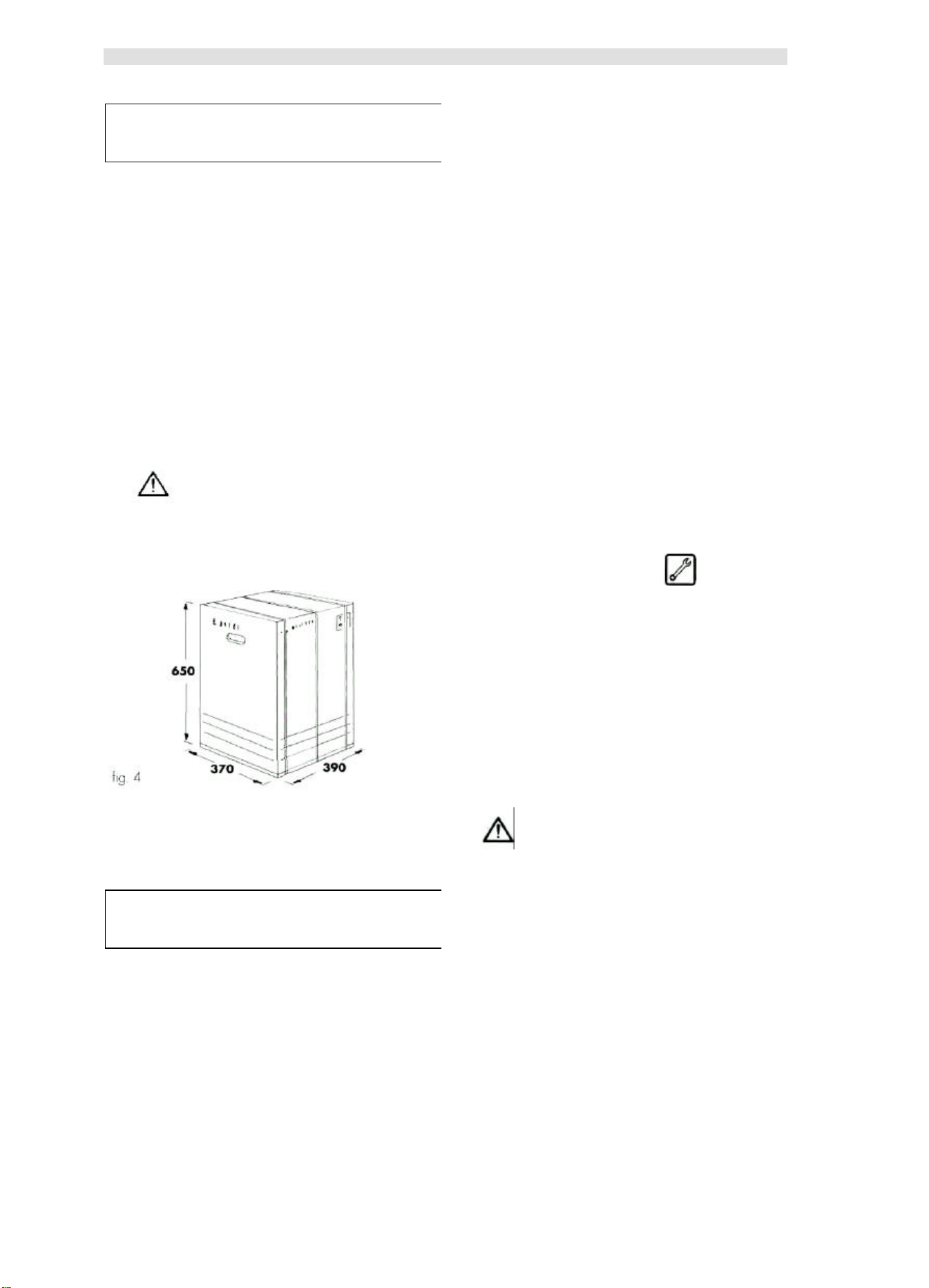
• The vending machine is contained in cardboard packaging
with reinforced base (refer to fig. 4).
Danger
The vending machine packaging can stand
50 kg in weight, therefore do not stack
more than two vending machines.
• The vending machine should be stored in its original
packaging, in dry and non-dusty places.
• Do not dip the vending machine in water.
4.2 Operator requirements
With the purpose of proper vending machine operation and
safety, two type of operators with different requirements are
defined:
Maintenance technician
Specialized person responsible for vending machine
installation, first adjustment and, more in general, specific
maintenance.
4 - SAFETY
4.1 General safety rules
• Carefully read this publication before using the vending ma chine.
• It's absolutely forbidden to deactivate the safety devices in-
stalled on the vending machine.
6
User
Person with a medium specialization level that has read the
norms in the present manual and has followed a proper
training course as per laws in force.
The User is allowed to start the vending machine, adjust its
working parameters, stop it, carry out its norma loading and
coin collection operations, and finally to carry out its external
cleaning.
Danger
The User is forbidden to carry out the operations indicated in
the present manual as a specific competency of the maintenance technician.
4.3 Installed safely devices
- A safety valve protects the vending machine from over
pres sures in the hot-water production system.
- The heater is protected against overheating by a
thermostat and a thermal fuse.
- A series of micro-switches controls the position of the drip
tray (ref. 16, fig. 1), of the vending machine internal
access door (ref. 29, fig. 1), of the coffee unit (ref. 13, fig.
1), and of the coffee grounds tray (ref. 14, fig. 1). If one of
the components is not in the proper position, the relevant
micro-switch stops vending machine operation and the
display will show the message informing about
component out of place.
English
5 - COMMAND AND
INSTRUMENT DESCRIPTION
Important
The vending ma chine is delivered with the dispensing
keys already programmed on standard values.
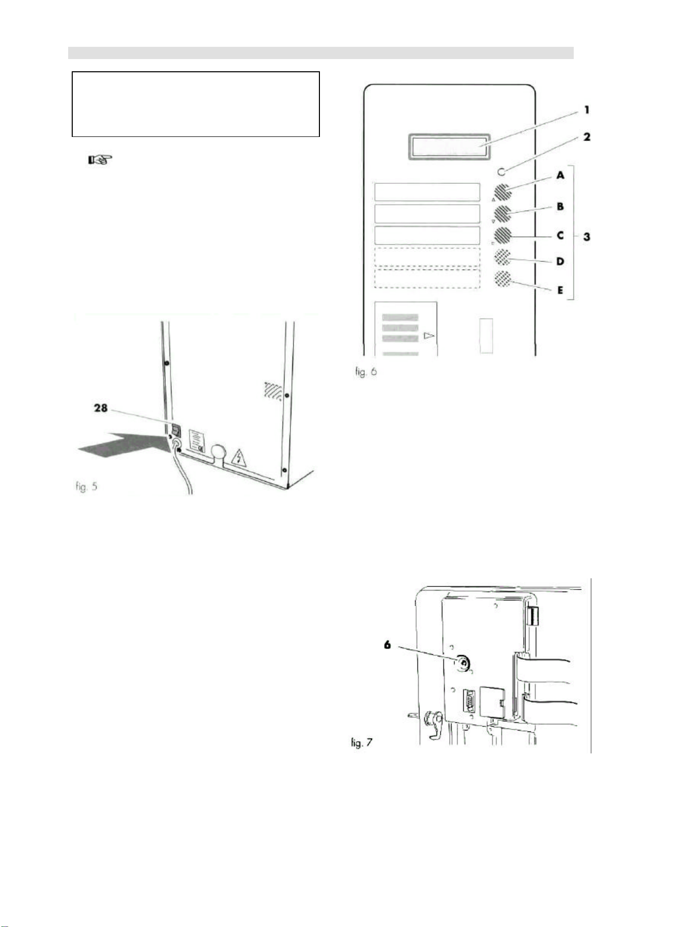
Main switch (ref. 28, fig. 5)
it's located in the lower right back side of the vending ma -
chine.
On the "I" position it turns the vending machine on
(enabling electric functions)
On the "0" position it turns the vending machine off
(disables electric functions)
Keypad D.A. 5P (ref. 3 fig. 6]
It's composed of 5 re-programmable keys that when pressed
control the dispensing of the same number of drinks,
identified from top to bottom as A - B - C - D - E (ref. 3, fig.
6).
The correspondence between key and dispensed drink is at
the User's discretion.
The A - B - C - D - E keys (ref. 3, fig. 6) are also used to
perform maintenance.
(refer to "7 - Programming")
Keypad D.A. 3P (ref. 3 fig. 6)
It's composed of 3 re-programmable keys that when pressed
control the dispensing of the same number of drinks,
identified from top to bottom as A - B - C.
The correspondence between key and dispensed drink is at
the User's discretion.
The A - B - C keys (ref. 3, fig. 6) are also used to perform
maintenance.
(refer to "7 - Programming")
Display (ref. 1, fig. 6]
It's composed of 2 lines with 16 characters each, and has
the duty of displaying the messages relating to the
operations (in progress or to be performed) and the
possible out -of-service conditions.
Red indicator light (ref. 2, fig. 6)
When the light is on it indicates that the vending machine
is not ready for drink dispensing.
In any case the display (ref. 1, fig. 6) supplies the
indications on vending machine operative or out -of-service
status.
Reset key [ref. 6, fig. 7]
It's located on the internal part of the door and may
perform the following functions:
a) Resetting "OUT OF SERVICE" (out -of-service)
indications (refer to " Display messages").
b) Water circuit filling (refer to " 6.2 Water connection").
7
English
6.2 Water connection
6 - INSTALLATION
Machine with tank
(Type D.A. 3P standard e D.A. 5P standard)
Danger
The presence of strong magnetic fields or the vicinity of
electric machines generating strong disturbances might
cause malfunctioning of the vending machine electronic
control.
Install the vending machine in a protected environment
with temperatures varying between 10°C and 40°C. Make
sure that no tampering occurred during transportation,
checking that original packaging is intact and closed with
straps. Move the closed box near the installation area
(refer to "3 Handling and storage"), cut the straps and lift
the carton. Verify the state and the model of the vending
machine contained in the carton.
Check the contents of the accessory envelope attached to
the vending machine (refer to "6.2 List of accessory
equipment). Remove the vending machine from the
original packaging. It is advisable to keep the latter for later
transportation or moving. Free the vending machine from
residual packaging.
Important
Possible packaging element disposal shall be performed
in compliance with the laws in force in the country while respecting the environment.
Place the vending machine on a horizontal plane surface
having adequate size and capable of standing its weight.
The bearing surface shall not exceed an inclination of 2°.
Important
To ensure proper vending machine ventilation, the
machine's rear panel should be at least 8 cm away from
walls, partitions, etc.
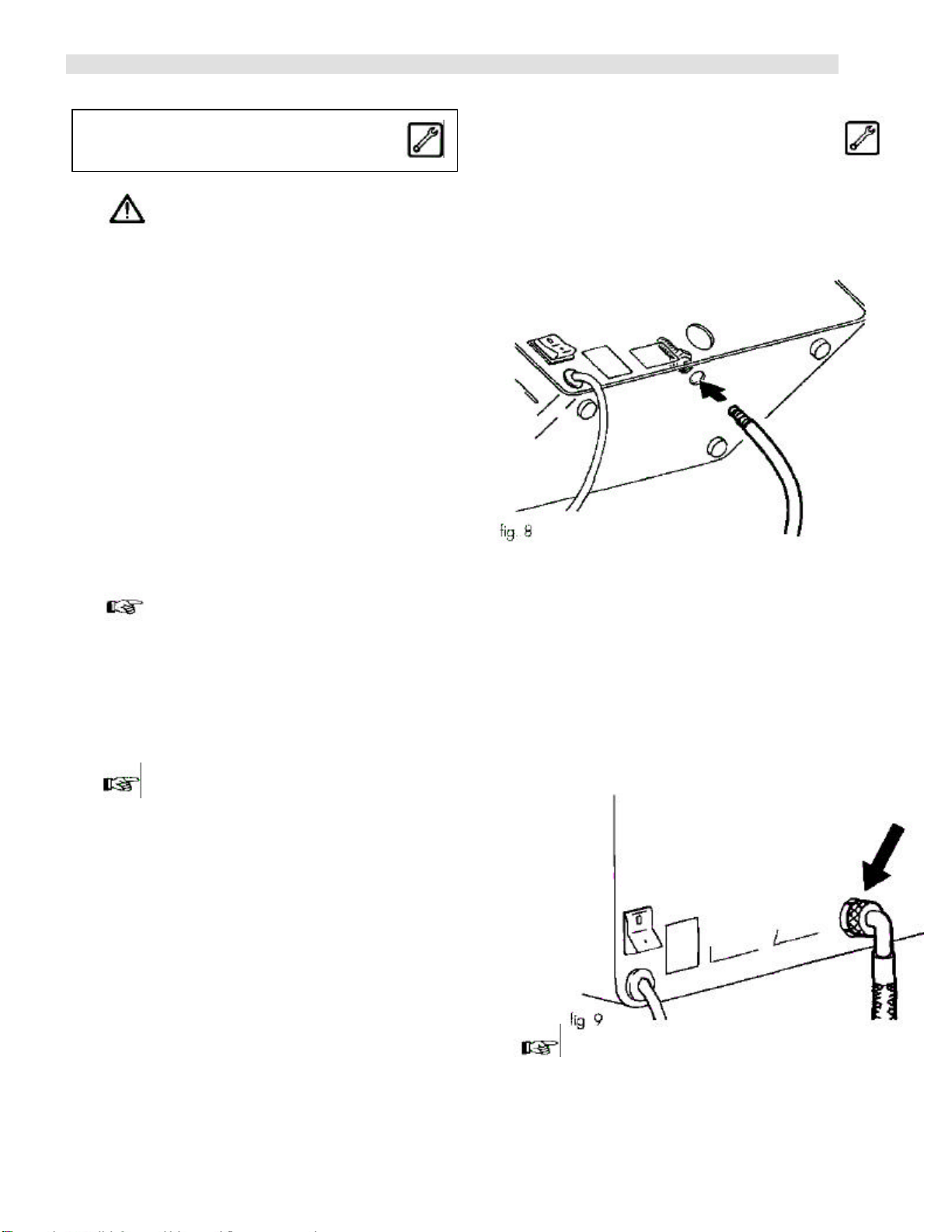
- Insert the water aspiration tube in the special
connection under the dispenser (fig. 8).
- Insert the tube in the can.
Machine with direct waterworks connection
(Type D.A. 3P R.I. e D.A. 5P R. .)
- Connect the vending machine to a drinking water
distribution conduit having a pressure between 1,5
and 8 bar. To do this use a loading tube with
adequate characteristics and connect it to the G3/4"
coupling located on the vending machine back
panel (fig. 9).
Do not cover the vending machine with cloths or other
things.
6.1 List of accessory equipment
• Micro operation key for safety system deactivation
• 4 screws and nuts for coiner fixing
• Series of stickers with prices and accepted coins
• Series of stickers with instructions and dispensed products
• 1 coupling for water pipe to tank (only for pre-set version
with tank)
• 1 wrench for mix fan fitting
• 1 Operation and Maintenance booklet
It is advisable to feed the vending machine with
treated water by means of a decalcifying device,
especially when the water has high calcium and
magnesium salts content (hard water).
Important
8

English
6.3 Electrical connection
The vending machine is pre-set for electrical operation with a
single-phase voltage whose value is stated in the
identification tag (Refer to "2.4 Vending machine
identification") (fig. 2).
Danger
The connection point of the electric outlet must be
located in a place that can be easily reached by the
user, so that he can easily disconnect the vending
machine from the power supply when required.
Before connecting, make sure that:
• The mains supply voltage of the outlet the vending machine
is connected to corresponds to the one indicated on the
tag.
• The electric installation of the place where the vending machine is going to be installed complies with the laws in
force, and has the characteristics enabling it to stand the
required maximum load indicated on the tag.
- Insert the coiner and fix it by using the 4 supplied screws
with nuts (fig. 1 2).
- Connect the flat cable to the coiner (fig. 12).
Check the electric installation's compliance with the safety
rules in force; in case of doubt, require an accurate electric
installation survey by qualified professional staff.
Danger
The use of adapters or patch cords is forbidden.
6.4 Fitting the PARALLEL 12 V d.c. coiner
Only 1 2 V d.c. parallel or mechanical coiners may be
used on this vending machine.
- Remove the token accepting device support (fig. 11).
- Drill a hole on the keypad panel (fig. 1 1).
- Connect the flat cable to the electronic board (fig. 1 3).
fig. 13
The Company disclaims all responsibilities for
damages to vending machine, properties and people
arising out of improper installation of the payment
system; this responsibility falls directly on whoever
performed the fitting.
Important
9

English
6.5 Insertion of the Clock module
Danger
This operation should be carried out by the maintenance
technician.
The "Clock Module" device manages the following functions:
- the times when free dispensing is performed;
- Vending machine start up and shutdown times;
- the times when discounts or price rises should be
applied, and their amount;
- cleaning frequency
The following operations should be performed to insert the
module:
- disconnect the device from the power supply;
- open the vending machine door (ret. 29, fig. 1) and
remove the small door (ref. D, fig. 14);
- insert the module (ref. A, fig. 14) in the electronic board
connector.
To insert the nation key it's necessary to perform the
following operations:
- Disconnect the power supply.
- Open the vending machine internal access door (fig. 14).
- Insert the key (ref. B, fig. 14) in the electronic board
connector.
- Re-close the door.
6.7 Serial port connection
Danger
This operation should be carried out by the maintenance
technician.
A serial port (ref. C, fig. 14) is installed beside the "clock
module" connector.
Through the serial port the vending machine may be
connected to a Personal Computer or to the devices supplied
to the AUTHORIZED SERVICE CENTRES in order to carry
out inspections and programming operations.
Important
The module (ref. A, fig. 13j is inserted properly when the
reference mark is in the lower part (fig. 14).
- Re-fit the small door (ref. D, fig. 14).
- Re-close the door (ref. 29, fig. 1).
6.8 Affixing labels and stickers
Separate the accessory drink labels supplied with the
machine by following the broken line. Apply the adhesive
prices on the drink labels. Insert the tags in the special
housings (fig. 15-16) through the slots located in the internal
part of the door (ref. 29, fig. 1).
6.6 Insertion of the Nation key
Danger
This operation should be carried out by the maintenance
technician.
The "nation key" contains the following data:
- Language used by the display.
- Software settings connected with the country of
operation.
Important
The vending machine does NOT work without the "nation
key" inserted, it is therefore necessary to insert it.
After having inserted the "nation key", the machine will
refuse the introduction of keys for different countries.
10

English
7 -PROGRAMMING
This chapter describes how to set and/or change the parameters
programmed on the vending machine.
It is then advisable to read it carefully, performing the intervention
only once the proper sequence of operations to be performed has
been understood,
In order to better understand the issue, its necessary to define a
few terms that are going to be used in this chapter:
- The term "digit" stands for the number or the letter that together
with others, composes the "parameter" .
- The term "parameter" stands for the whole of the "digits" that
sets a certain function.
The Programming system is developed in four levels:
- The first level includes the five main items of the programming
menu;
- The second eve displays all the functions of each programming
menu item;
- The third level displays the memorized settings for each pro grammable function;
- The fourth level displays the modifiable parameters of the func-
tions.
The five main items of the Programming menu are:
• system management
• payment systems
• drink preparation
• vending handler
• time management
• change current date and time;
• insert text lines that will be visualized on the display during drink
dispensing, when the vending machine is on standby and when it
stops for out-of-service or due to a problem;
• activate the pre-selection that displays the balance cash amount
for drink dispensing.
PAYMENT SYSTEMS
Its' the second main item of the programming menu.
It allows the setting of all the following parameters associated with
the different payment systems:
• coin values;
• enabling multi-product dispensing (residual credit management);
• OVER-PAY time (residual credit confiscation),
BEVERAGE PREPARATION
Its' the third main item of the programming menu.
In model D.A, 5P, it allows the preparation of the five dispensable
drinks.
Each drink may be obtained by combining coffee bean grinding
with the soluble product and water. Dispensing shall be performed
according to the set sequence. The quantity of ground coffee shall
be set for each drink, together with the quantity of soluble product
and water, and the dispensing speeds of the soluble product and
water.
SYSTEM MANAGEMENT
It's the first main item of the Programming menu.
It allows to set the parameters concerning machine operation and
verify its use status (by reading the counters).
Moreover, its' possible to assign a code to the vending machine,
display the registration number and insert or modify the password
that gives access to programming.
The displayable counters refer to:
- coffee;
- water;
- drinks;
- soluble products (only D.A. 5P)
For each of them the counter reports the number of performed vends
and the executable ones. Beyond such limit the vending machine will
stop dispensing drinks. Each counter may be zeroed. The number of
possible vends (BLOCKS) can be modified.
System Management allows to:
• change the maximum and minimum vending machine operating
temperatures;
In model D.A. 3P, it allows the preparation of the three dispensable
drinks.
Each drink is obtained from the combination of bean coffee grinding
and water. Each drink requires the setting of coffee and water
quantity.
SALES MANAGEMENT
It's the fourth main item of the programming menu.
In model D.A. 5P, it allows to set the value of four prices to be
associated with the five drinks.
In model D.A. 3P it allows to set the value of four prices to be
associated with the three drinks.
TIME MANAGEMENT
It's the fifth main item of the programming menu. It allows to set the
following vending machine functions to be performed within certain
time bands:
• free product dispensing;
• machine start up and shutdown time;
• time bands within which discounts or rises should be applied to
drink prices;
• hydraulic circuit automatic cleaning
11

English
7.1 Programming structure
Part 2
Part 1
Continues
12
Continues

English
? A - "UP" key
Allows upwards scrolling of the various menus, and
rises the displayed values during the programming
phase. In the model D.A. 3P, it allows the passage
between levels after parameter memory-storage.
? B - "DOWN" key
Allows downwards scrolling of the various menus, and
reduces the displayed values during the programming
phase. In the model D.A. 3P, it allows the passage
between levels after parameter memory-storage.
E C - "ENTER" key
It changes or memory-stores the displayed parameter.
D - "CANCEL" key
It allows returning to the upper programming level after
parameter confirmation (only D.A. 5P).
7.3 Programming mode access
End
7.2 Key functions
The operating parameters of the vending machine may be
programmed directly from the product selection keypad. In
the model D.A. 5P the dispensing keys are A - B - C - D (ref.
3, fig. 17).
In model D.A. 3P the dispensing keys are A - B - C (ref. 3, fig.
171.
The vending machine is equipped with a programming menu
structured on four levels. Accessing programming requires:
- Starting the vending machine by means of the main switch
(ref. 25, fig. 1) while pressing the "UP" and "ENTER" keys
at the same time (ref. A and C, fig. 17).
"SYSTEM MANAGEMENT" (system management)
appears on the display.
Important
The inserted digits and the modified parameters
should be always confirmed with the "ENTER" key.
There are small symbols beside the keys recalling the
functions performed by the keys during the programming
phase.
If a programming password has been created for the
vending machine, the display will visualize "PASSWORD
0000" , with the cursor flashing on the first digit . You must
then:
- Enter the access password using the "UP" and "DOWN" keys.
Important
Each entered digit should be confirmed with the
"ENTER" key.
- After each confirmation the flashing cursor passes to the
following digit.
Proceed similarly up to the fourth one.
- After having confirmed the fourth digit the display will visu alize "SYSTEM MANAGEMENT".
- Scroll the various menu items with the "UP" and "DOWN"
keys.
If no password was assigned, programming is accessed
directly.
13

English
7.4 Selection of the parameter to be
changed or displayed
The five menu items can be scrolled on the display to verify
their parameters and eventually modify them. This requires:
- Entering function programming (refer to "7.3
Programming
Mode Access")
- Scroll menu items with the "UP" and "DOWN" keys.
- Stop the selection on the menu item managing the
function to be verified or modified.
- Press the "ENTER" key to enter in the item.
- Scroll the various functions with the "UP" and "DOWN"
keys.
- Stop the selection on the function whose parameters
should be displayed or modified.
- Press the "ENTER" key to display the parameter.
7.5 Changing and saving parameters
Changing or memory-storing parameters requires:
- Displaying the parameter to be changed (refer to "7.4
Selection of the parameters to be changed or
modified").
- Pressing the "ENTER" key to access the parameter to
be modified. The flashing cursor places itself on a digit.
- Increasing or decreasing the digit value by means of the
"UP" and "DOWN" keys.
Pressing the ENTER" key the displayed digit is stored to
memory and replaces the previous one, while at the
same time the cursor moves to the next digit.
- Following the same procedure to set the remaining
digits. After having completed the digit change, confirm
the new parameter with the "ENTER" key. If the change
is accepted the flashing cursor disappears.
Operate in the same way for all the letters to be entered.
The maximum number of letters that can be inserted is 16.
Once the insertion is completed press "ENTER" twice.
If you want to move to a further parameter press the "UP" or
"DOWN" keys.
• In model D.A. 5P to exit the modified parameter and
change level, press the "D - Cancel" key.
Once all the parameters have been changed and stored to
memory, press the "D - Cancel" key for as many times until
you reach the function allowing exit from Programming "EXIT
PROGRAM Y/N"
• In the model D.A. 3P to exit the modified parameter or
change level, press the "UP" or "DOWN" keys.
Once all the parameters have been changed and stored to
memory, press the "UP" o "DOWN" keys for as many times
until you reach the function allowing exit from Programming
"EXIT PROGRAM Y/N".
7.6 Menu description
N.B.: The numbers to be entered for each Hem are not
referred to a measure unit (gr., ml., etc.), and are
mere reference values.
Important
The following description of the menus refers to
model D.A. 5P, but it may be referred also to model
D.A. 3P without substantial differences.
Sometimes the parameter to be stored to memory must be
chosen among a list of pre-set parameters ("YES" and "NO",
"WEEKDAYS" (weekdays), etc...). In these cases the "UP"
and "DOWN" keys are used to scroll the flashing cursor or
visualize the possible choices on the display.
Example
Setting "YES" or "NO" in a function requires:
- Selecting the function.
- Accessing the change level by means of the "ENTER"
key. Upon access a selection signal appears on one of
the two writings: "Y" (YES) or "N" (NO).
- Using the "UP" or "DOWN" keys to select "Y" (YES) or
"N" (NO).
- Pressing "ENTER" to confirm the choice. Pressing
"ENTER" automatically moves to the access level of the
function.
Inserting text in a function requires:
- Selecting the function.
- Pressing "ENTER" to type the text.
The flashing cursor appears under the first letter on the
left.
- Using the "UP" or "DOWN" keys to scroll the letters.
- Pressing "ENTER" to confirm the letter. The cursor
moves to the following letter.
First main voice of the
programming menu
SYSTEM MANAGEMENT
Press "ENTER" to enter item functions.
VM CODE 001007
This function allows the assignment of an identification code
to each device.
To insert the code you should follow the procedure described
in chapter "7.5 Changing and saving parameters".
COUNTERS
This function allows the control of the number of drink,
soluble products and water vends.
Pressing "ENTER" gives access to the lower level where
counters are listed.
The lower line of each single counter displays the total vends
after the letters "T" and "P".
14

English
T:
000000
P:
00000
T:0000Z5 P:00015
T:
000005
P:
000003
T:
000005
P:
000003
The number after the letter "T" corresponds to the total
performed vends, and cannot be zeroed.
The number after the letter "P" corresponds to the total vends
performed since the last zeroing, (partial total) and may be
zeroed with the "RESET" function.
COUNT.
COFFEE
Displays total and partial coffee vends.
COUNT. BEVERAGE
Displays total and partial vends of all drinks, model D.A. 5P
dispensing keys A- B-C- D (ref. 3, fig. 17), model D.A. 3P
dispensing keys A - B - C (ref. 3, fig. 17). Press "ENTER" to
access the single counters.
BEVERAGE A
BEVERAGE B
BEVERAGE C
T:000005 P:000003
BEVERAGE D
T:000005 P:000003
BEVERAGE E
T:000005 P:000003
Using the "UP" and "DOWN" keys it's possible to visualize
total and partial vends for each single drink, model D.A. 5P
dispensing keys A - B - C - D (ref. 3, fig. 17), model D.A. 3P
dispensing keys A-B-C (ref. 3, fig. 17|.
COUNT. SOLUBLE
Counting function for soluble products only for model D.A.
5P|. Press "ENTER" to access the display of the single
counters.
SOLUBLE 1 T:000010
P:000004
Displays total and partial soluble product vends.
WATER COUNTER T:000010
P:000004
Displays total and partial water vends.
RESET COUNTER
This function allows zeroing all partial counters.
Press "ENTER" to access this option.
RESET COUNTER
->Y<- N
To set the function follow the procedure described in chapter
"7.5
Changing and saving parameters".
By confirming the etter "Y" the counters are zeroed.
STOP
This function allow the setting of a maximum number of drink
vends, quantity of soluble powder, or coffee grounds
disposals, in order to give a set frequency to the operations
or interventions. Once the set limits are reached, the vending
machine stops dispensing (block).
The red led on means that the drink is not available
(blocked). In the lower line, the first sequence of numbers
refers to the dispensed or expelled quantity of drinks or
product after the last zeroing; the second sequence of
numbers after "LIM:" indicates the maximum quantity to be
dispensed or expelled. To set the maximum number follow
the procedure described in "7.5 Changing and saving
parameters" With the second sequence of number set as
"LIM: 0000" dispensing is performed with no block limit.
Press "ENTER" to access the selection of the various blocks.
STOP COFFEE
00000 LIM:00000
This function allows the setting of a number of coffee vends
before blocking.
STOP BEVERAGE
This function allows to set the number of drink vends, model
D.A. 5P dispensing keys A - B - C - D (ref. 3, fig. 17), model
D.A. 3P dispensing keys A - B - C (ref. 3, fig. 17), before
blocking. Press "ENTER" to display the blocks for the single
drinks.
BEVERAGE A
00000 LIM:00500
BEVERAGE B
00000 LIM:00500
BEVERAGE C
00000 LIM:00500
BEVERAGE D
00000 LIM:00500
BEVERAGE E
00000 LIM:00500
Use the "UP" and "DOWN" keys to visualize the block
parameters for each single drink, model D.A. 5P dispensing
keys A - B - C - D (ref. 3, fig. 17), model D.A. 3P dispensing
keys A - B - C (ref. 3, fig. 17).
STOP SOLUB.
This function allows setting the dispensing of a certain
quantity of soluble powder: once this quantity is reached the
dispensing of all the drinks containing such soluble powder is
blocked., The counter drops by a unit only when a dose equal
to the one of the drink that uses its highest quantity is
dispensed. The use of a lower dose than the reference one is
counted as a fraction. Press "ENTER" to access soluble
product block display.
15

English
T:095
*D.A. 5PN SAECO*
SOLUBLE 1
00000 LIM:00500
Press "ENTER" to display the soluble product block
parameter.
STOP WATER
00000 LIM:00500
This function allows the setting of a number of water vends
before blocking, Press "ENTER" to display the block
parameter.
CLOCK
*09:33 L 05 MAR 97*
This function allows the setting of the current hour, minute, day,
month and year. To set the function follow the procedure
described in chapter "7.5 Changing and saving parameters".
Repeat the same procedure for all function data.
TEXT STAND-BY
STOP GROUNDS
00000 LIM:00100
This function allows the setting of a number of coffee
grounds expulsions before blocking. Press "ENTER" to
visualize the block parameter.
This function allows the setting of the text that scrolls on the
display when the vending machine is on standby. To set the text
follow the procedure described in chapter "7.5 Changing and
saving parameters".
RESET STOP
This function allows the zeroing of all the product quantity
partial counters. Press "ENTER" to access this option.
RESET STOP
->Y<- N
To set this function follow the procedure described in
chapter "7.5 Changing and saving parameters": Confirming
the letter "->Y<-" zeroes the counters.
MIN. TEMPERATURE
This function allows setting the temperature maintained by
the de vice for a few minutes (about 4) after a drink has
been dispensed The lower line of the display shows the set
value, expressed in degrees centigrade. To set the
minimum maintained temperature follow the procedure
described in chapter "7.5 Changing and saving parameters".
MIN. TEMPERATURE
T:100
This function allows the setting of the temperature reached
by the device after a certain period of inactivity (about 4
minutes) to compensate the natural temperature fall. The
lower line of the display shows the set value, expressed in
degrees centigrade. To set the inactivity temperature follow
the procedure described in chapter "7.5 Changing and
saving parameters".
MECH. COUNTER
BEVERAGE
This function allows, only if the mechanic pulse counter is
fitted, to enable or not the total or partial counting of drink
vends. To obtain drink vend total count enable the "MECH.
COUNTER BEVERAGE" function. To obtain drink vend total
count enable the "MECH. COUNTER BEVERAGE" or
"MECH. COUNTER SOLUBLE" functions (only D.A.5P)
or"MECH. COUNTER COFFEE". To select the count to be
enabled follow the procedure described in chapter "7.5
Changing and saving parameters".
16
TEXT DISPENSING
DISPENSING
This function allows the setting of the text that scrolls on the
display when the vending machine is dispensing a drink. To set
the text follow the procedure described in chapter "7.5 Changing
and saving parameters".
TEXT OUT OF SERV
OUT OF SERVICE
This function allows the setting of the text that scrolls on the
display when the vending machine stops due to a fault. To set
the text follow the procedure described in chapter "7.5 Changing
and saving parameters".
PRESELECTION
YES
This function allows the enabling or not of drink price display.
The lower line of the display shows the set parameter. By
enabling this function (YES) the user is allowed by pressing the
key relating to a drink to visualize its price on the display. After a
few seconds the visualization is canceled. Press "ENTER" to
access this option.
PRESELECTION
->Y<- N
To set this option follow the procedure described in chapter "7.5
Changing and saving parameters".
SERIAL NUMBER
909024
It's the device registration number, set by the manufacturer,
and it can only be displayed.
CHANGE PASSWORD
This function allows the setting of a password (0000 base
setting) to prevent unauthorized personnel from directly
accessing programming functions. If a password is set, it shall a
ways be typed before accessing programming. Press "ENTER"
to access this option.

English
SEQUENCE:
1000
SOLUBLE
1: 012
WATER
1: 030
% SOLUB.
1: 160
COFFEE:
050
COIN
01:00050
COIN
02:00050
COIN
03:0
0050
COIN
04:00050
COIN
05:00050
COIN
06:00050
NEW PASSWORD
Menu item that appears before changing the password.
Press "ENTER" to set the new password.
NEW PASSWORD
CODE: 0000
A flashing cursor appears under the first digit after "CODE:...".
To set the password follow the procedure described in
chapter "7.5 Changing and saving parameters". By pressing
"ENTER" the machine moves automatically to the previous
level "NEW PASSWORD".
Warning
Write down the new password because in case of loss
access to programming will he impossible.
Second main item of the
programming menu
PAYMENT SYSTEM
Press "ENTER" to access the item functions.
COIN VALUES
This function allows the association of a value to all the
selectable coins.
Press "ENTER" to display the coin list.
COIN VALUES
COIN VALUES
COIN VALUES
COIN VALUES
COIN VALUES
COIN VALUES
Press "ENTER" to display the value of the first coin. Press the
"UP" and "DOWN" key to scroll the list of coins. To modify the
coin value follow the procedure described in chapter "7.5
Changing and saving parameters". The coin value falls within
a nation key - pre-set range. Pressing "ENTER" automatically
moves the display to the previous level "COIN VALUES".
This function allows or not the use of residual credits to
purchase other drinks.
The lower line of the display shows the set parameter.
By enabling the function (YES) it's possible to use possible
residual credits. On the contrary (NO), once the "OVER
PAY", time is elapsed, the vending machine confiscates the
residual credit.
Press "ENTER" to access this option.
To set this option follow the procedure described in chapter
"7.5 Changing and saving parameters".
This function determines the maximum time (expressed in
seconds! after which the vending machine confiscates the
residual credit visualized on the display.
To change the value follow the procedure described in
chapter "7.5 Changing and saving parameters". By setting
the value to "000000" the function is disabled. By pressing
"ENTER" the display automatically moves to the function
access level.
Third main voice of the
programming menu
Press "ENTER" to access this item's functions.
This function allows to display the dispensable drinks in
sequence, model D.A. 5P dispensing keys A - B - C - D (ref.
3, fig. 17), model D.A. 3P dispensing keys A - B - C (ref. 3,
fig. 17). Press "ENTER" to access the display of the items
composing the single drinks.
This level displays the dispensing sequence, quantities and
speeds of the products composing each single drink.
Press the "UP" and "DOWN" keys to scroll the drink
composition.
MULTIVEND YES
MULTIVEND
->Y<- N
OVER PAY 180
PREPARING BEVERAGE
BEVERAGE A
BEVERAGE A
BEVERAGE A
BEVERAGE A
BEVERAGE A
BEVERAGE A
(only D.A. 5P)
17

English
WATER
1: 030
SEQUENCE: C100
SOLUBLE
1: 045
COFFEE:
050
The upper line of the display will always show the selected
drink, while the second line shows the sellable parameters
from time to time.
BEVERAGE SEQUENCE:
A 1000
This item allows the setting of the sequence with which the
products composing the drink shall be prepared and
dispensed (in this case A). Up to three products may be
inserted. To change the value, which varies between 0, 1 and
C, follow the procedure described in chapter "7.5 Changing
and saving parameters"
Important
In this function the digit 0 corresponds to no product, as a
consequence the digit combination corresponding to
"0300" or "0030" will always provide for the dispensing of
product 3
Depending on the sequence, it will be asked to set the
parameters relating to the products that shall be dispensed in
the drink.
Press the "UP" and "DOWN" keys to scroll the drink
composition.
BEVERAGE A
(Only D.A. 5P)
It defines the quantity of soluble product to be mixed with
water. The lower ine shows "SOLUBLE 1:045". 045
indicates that 45 units of soluble product will be used. To
modify the soluble product quantity follow the procedure described in chapter "7.5 Changing and saving parameters".
Important
The quantity of soluble powder may be adjusted from 0 to
250 with 1-by-1 steps.
The product is not dispensed when the parameters are set
on "0000"
BEVERAGE A
% SOLUB. 1: 160
It indicates the speed with which soluble powder and water
are dispensed in drink A.
Important
By setting the value on 10 the pump works at maximum
flow rate, while the soluble product is dispensed by
impulses at minimum flow rate.
By setting the value on 100 both the soluble product and
water are dispensed at maximum flow rate.
By setting 190 the pump works by impulses at minimum
flow rate, while the soluble product is dispensed at
maximum flow rate.
To change the dispensing speed follow the procedure
described in chapter "7,5 Changing and saving parameters",
Important
Soluble powder and hot water may be adjusted between
10 and 190, with 10-by-10 steps.
BEVERAGE A
If defines the quantity of coffee to be dispensed.
The lower line shows "COFFEE: 050".
050 means that 50 ground coffee units shall be dispensed.
To change the coffee quantity follow the procedure described
in chapter "7.5 Changing and saving parameters".
Important
The quantity of dispensable coffee may be adjusted from 0
to 500 with 2-by-2 steps.
The product is not dispensed when the parameter is set
on "00000"
Example of a drink with one soluble product and coffee.
BEVERAGE A
It defines the quantity of water to be mixed with the soluble
powder or coffee.
When "WATER 1:045" appears on the lower line, this
means that water will be mixed with the soluble product or
with coffee. 045 means that 45 water units will be dispensed
in the soluble product or in coffee.
To modify the water quantity follow the procedure described
in chapter "7.5 Changing and saving parameters".
Important
The quantity of hot water may be adjusted from 0 to 250
with 1-by-1 steps.
The product is not dispensed when the parameters are set
on “0000"
18
BEVERAGE C
The letter "C", displayed in the first line indicates the drink
corresponding to the C key (upper third in the keypad - ref. 3,
fig. 1 7).
The four digits indicate the products (coffee and/or soluble
product) shall be used to compose the drink.
In this example drink dispensing, selectable with the C key,
shall be obtained by mixing water, coffee and soluble
product.
N.B.: the same drink may be obtained with the same
products, set in different sequence (e.g. C001, or 0C01, etc.).
Pressing the "DOWN" key moves the display to the next item.

BEVERAGE C
SOLUBLE
1: 012
:abcde
:abcde
:abcde
:abcde
0200
:abcde
Press "ENTER" to access the item functions.
The second line of the display shows the currently assigned value (e.g.
200)
besid
e the
It represents the quantity of soluble product used in the drink
C (ref.
3, fig. 17).
Pressing the "DOWN" key moves the display to the next item.
BEVERAGE C
WATER 1: 030
It represents the quantity of hot water dispensed in drink C
with the
soluble product.
Pressing the "DOWN" key moves the display to the next item.
BEVERAGE C
% SOLUB. 1:160
It indicated the speed with which the soluble product in the container (ref. 1, fig. 1 8)
and water are dispensed in drink C (ref. 3,
fig. 17).
Pressing the "DOWN" key moves the display to the next item.
BEVERAGE COFFEE: C 050
It represents the quantity of ground coffee used in the drink C (ref.
3, fig. 17).
Pressing the "DOWN" key moves the display to the next item.
English
dure described in chapter "7.5 Changing and saving parameters".
Use the "UP" and "DOWN" keys to move to a further "PRICE...:..." item.
Repeat the operation sequence for each price whose value is to be modified.
BEVERAGE PRICES
This function allows the Association of each drink with one of the prices previously
set in "BEVERACE PRICES". Press "ENTER" to access item display.
BEVERAGE PRICES 1- 0000
BEVERAGE PRICES 2- 0000
BEVERAGE PRICES 3- 0000
BEVERAGE PRICES 4- 0000
This level displays in sequence the Price/Drink associations set for each single item.
Important
In model D.A. 3P the second line of the display only shows
the letters abc, because the price has to be associated with
only three drinks.
Press "ENTER" to change the Drink/Price associations.
Fourth main item of the
programming menu
SALES MANAGEMENT
PRICE VALUES
This function allows the setting a value for each price.
Steps and ranges are pre-set.
Press "ENTER" to access the display of the price va ues.
PRICE VALUES PRICE 01:
00000
PRICE VALUES PRICE 02:
00000
PRICE VALUES PRICE 03:
00000
PRICE VALUES PRICE 04:
00000
This level displays in sequence prices and their values, Press "ENTER" to
access the change of the single values.
BEVERAGE 1-
The second line of the display shows a first group of digits "1- 0200..." that cannot
be changed in this function because they're the previously set prices. The second
group of digits "...:abcde" shows the dispensable drinks, model D.A. 5P dispensing
keys A - B - C - D (ref. 3, fig. 17), model D.A. 3P dispensing keys A - B - C (ref. 3,
fig. 17), which can be associated with prices.
N.B: LOWER CASE LETTERS indicate that the drink IS NOT associated with the
displayed price, while UPPER CASE LETTERS indicate that the drink IS
associated with the displayed price.
- Use the "UP" and "DOWN" keys to scroll all the available price values.
Press "ENTER" to change the Price/ Drink association The flashing cursor
appears under the first letter. If the displayed price is to be associated with one of
the five possible drinks, the chosen letter should be transformed from lower to
upper case by using the "UP" and "DOWN" keys. Press "ENTER" to store to
memory. The cursor automatically moves to the second letter. Follow the same
procedure to set the remaining letters.
- Use the "UP" and "DOWN" keys to move to a further "BEVERAGE PRICES" item.
To exit the function press the D (ref. 3, fig. 6).
PRICES
PRICE VALUES PRICE 01:
00000
item "PRICE 01:00200".
to scroll the values, and eventually change them, follow the proce-
19

YES
TIME RANGE
-
>Y<
-
N
mtwtfss
00:00
mtwtfss
00:00
mtwtfss
00:00
mtwtfss
00:00
0000
English
To set the two free dispensing periods, it's necessary to:
Fifth main item of the
programming menu
TIME MANAGEMENT
It may be displayed as an addition to the four main items by
inserting the clock module device. Press "ENTER" to access
the change of the single functions. Press "ENTER" to access
the item functions.
FREE VEND
This function allows the setting of when and how to dispense
drinks for free.
Press "ENTER" to access the display of the methods with
which free dispensing is performed.
FREE VEND ALWAYS
FREE VEND TIME RANGE
This level visualizes in sequence when and how drink
dispensing is free.
Press "ENTER" to access the change to the single items.
FREE VEND ALWAYS
The second line of the display shows the currently assigned
parameter. - Press "ENTER" to change it.
- A flashing cursor appears on the left.
- Use the "UP" and "DOWN" keys to vary the parameter
choice among the three available ones ("ALWAYS",
"NEVER" and "TIME RANGE").
- Press ENTER to store the choice to memory.
Confirmation automatically displays the previous level.
Use the "UP" and "DOWN" keys to move to the change
of the next item.
- Press "ENTER"
- A flashing cursor appears under the letters identifying the
week days, and by pressing the "UP" and "DOWN" keys the
character changes from upper to lower case.
N.B.: "Upper case character" = enabled day; "lower case
character" = disabled day.
- Press "ENTER" to store to memory. The cursor
automatically moves to the following letter.
- Follow the same procedure to set the remaining letters.
- Press "ENTER" to confirm the new value.
- Shutdown time is asked automatically (OFF1). Repeat the
operation sequence for each time interval whose value is to
be modified.
Once the last value has been selected and confirmed with
"ENTER", start up and shutdown time are asked for the
second band (ON2-OFF2). In case nothing is to be changed
press the D key, the fourth from the top in the model D.A. 5P
(ref. 3, fig. 17|. After having confirmed OFF2, exit form the
menu is automatic. In model D.A. 3P to exit from the function
it's necessary to scroll in a sequence the settable time bands
by means of the "UP" and "DOWN" keys.
ON/OFF TIME
This function allows the setting of the vending machine
automatic start up and shutdown time within a period of one
week. Press "ENTER" to set this option.
ON/OFF
TIME
To set this option follow the follow the procedure described in
chapter "7.5 Changing and saving parameters".
TIME ON1
TIME OFF1
FREE VEND
By choosing this option ("TIME RANGE") two time intervals
are available during which drinks may be dispensed for free.
For each one of them it's necessary to enter the starting time
(ON1 - OFF1) and the ending time (ON2 - OFF2).
Press "ENTER" to access the setting of the free dispensing
periods.
FREE VEND ON1
mtwtfss 00:00
FREE VEND OFF1
mtwtfss 00:00
FREE VEND ON2
mtwtfss 00:00
FREE VEND OFF2
mtwtfss 00:00
The modifiable parameter is on the second line of the
display.
20
TIME ON2
TIME OFF2
If "YES" is selected, two start up and shutdown time bands
(ON1 - OFF1, ON2 - OFF2) are required. To program days and
times follow the procedure as per the "FREE VEND - TIME
RANGE" item.
DISCOUNT
This function allows the setting of a discount on the drink
price, to be applied in the course of the week in two different
time bands. To set this option follow the procedure described
in chapter "7.5 Changing and saving parameters".
Important
the discount is settable with values varying from 10
to the lowest drink price, with 10-by-ten steps.

English
DISCOUNT ON1
mtwtfss
00:00
DISCOUNT OFF1
mtwtfss
00:00
DISCOUNT ON2
mtwtfss
00:00
DISCOUNT OFF2
mtwtfss
00:00
INCREASE
ON1
OFF1
ON2
mtwtfss
00:00
OFF2
mtwtfss
00:00
ON1
OFF1
mtwtfss
00:00
ON2
OFF2
EXIT
RINSING TIME
- The application of a discount automatically causes the opening of a following level.
->Y<- N
To set this option follow the procedure described in chapter
"7.5 Changing and saving parameters".
RINSING
mtwtfss 00:00
RINSING
RINSING
From this leve it's possible to set two time bands (ON1/
OFF1, ON2/OFF2), which determine the times in which the
discount should be applied.
To program days and times follow the procedure as per the
"FREE VEND - TIME RANGE" item.
0000
This function allows the setting of a rise on the drink price, to
be applied within one week in two different time bands.
The lower line shows "INCREASE TO BE APPLIED".
To set this option follow the procedure described in chapter
"7.5
Changing and saving parameters".
Important
Discounts are settable with values varying from 10 to the
lowest drink price, with 10-by-10 steps
Applying a price rise automatically causes the opening of a
following level.
INCREASE
mtwtfss 00:00
INCREASE
mtwtfss 00:00
INCREASE
INCREASE
From this level it's possible to set two time bands (ON1/
OFF1, ON2/OFF2), which determine the times in which the
price rises should be applied.
To program days and times follow the procedure as per the
"FREE VEND - TIME RANGE" item.
RINSING TIME
YES
This function allows the setting of two time bands within a
week, during which the machine performs automatic mixer
cleaning in sequence.
Press "ENTER" to set this option.
mtwtfss 00:00
RINSING
mtwtfss 00:00
If "YES" is selected, two start up and shutdown time bands
(ON1/ OFF1, ON2/OFF2] are required.
To program days and times follow the procedure as per the
"FREE VEND -TIME RANGE" item.
Once the parameters have been set and confirmed, it's
necessary to exit the programming function.
PROGRAM Y/N
This function allows the exit from the programming function at
any time.
It's on the same leve of the five main menu items, and its
visualization requires to:
- Press the D key, the fourth from top on model D.A. 5P
(ref. 3, fig. 6) until the items from the first level are
displayed. One of the five main menu items appears. In
model D.A. 3P scroll the settings first and than the
functions with the "UP" and "DOWN" keys, until one of the
five main programming menu items appears.
- Use the "UP" and "DOWN" keys to scroll them and display
the function to exit programming.
- Press "ENTER".
A cursor flashes under the letter ".../N".
- If it is not desired to exit programming it's necessary to
press the "ENTER" key. The same item will be displayed
but without the flashing cursor, and it will be possible to
scroll 1st. level functions.
- If instead the intention is to exit, it's necessary to use the
"UP" and "DOWN" keys to get the cursor to appear under
the letter "...Y...", then press "ENTER".
The display will show the text set in function "TEXT
STAND-BY".
Important
The vending machine keeps the programmed
parameters in memory even during power failure.
21

English
8 - USE OF THE VENDING
MACHINE
Important
Before using the vending machine if' necessary to
carefully read this publication and acquire a good general
knowledge of the vending machine.
After a period of inactivity of the vending machine it is
advisable to read chapter "8.6 First start of the Vending
machine" before re-using it.
8.1 Machine statuses
Depending on electric mains supply, the vending machine
may be in one of the following statuses:
Off and electrically isolated
- Main switch (ref. 25, fig. 1) in the "0" position.
- Only the programmed data maintenance memory is active.
On
- Main switch (ref. 25, fig. 1) in the "I" position.
- All the functions are active and the display (ref. 1, fig, 1) is
on.
Standby (vending machine off, but not electrically isolated]
- Main switch (ref. 25, fig. 1) in the "I" position.
- The "ON/OFF TIME" function is set on "YES".
The display and the programmed data maintenance
memory are active.
8.2 Manual start
This type of start up is required when the vending machine is
in the "Off and electrically isolated" status, (see 8.1 Machine
statuses). Follow the procedure described in "8.6 First start of
the vending machine", eventually leaving out the control of
the dispensed drink.
8.4 Drink dispensing
• Choose a drink among the ones available and identify the
corresponding price.
• Insert coins (or tokens) in the special slot (ref. 4, fig. 1) until
the display (ref. 1, fig. 1) visualizes the required amount.
Warning
It's impossible to insert coins once the amount equaling the
maximum vending price has been reached.
• Extract a cup and place it in the dispensing slot (ref. 9, fig. 1).
The display indicates "SELECT BEVERAGE" (select drink).
Warning
If a button is pressed corresponding to a drink having a
higher price than the one inserted, it's necessary to insert
more coins and press the chosen button once again.
The display indicates for a moment "INSERT COIN"
(insert token)
• Press the button corresponding to the chosen drink.
Warning
In order to avoid scalds, wait for the dispensing end signal
(red light turning off) before inserting your hand in the dispensing slot.
8.5 First start
of the Vending machine
Once the drinks dispensed by the vending machine have been
determined (see "7 - Programming"), get the products to be
inserted in the containers (coffee, soluble products, etc.).
Important
It is indispensable to use only soluble products declared to
be "suitable for automatic vending".
8.3 Programmed automatic start
This is possible when the vending machine is on "STANDBY"
and the "ON/OFF TIME" function is active and set. Vending
machine start up occurs at the programmed time.
Tank filling
Important
The lyophilized product must compulsorily be poured in its
container (ref. 6, fig. 1).
Do not put coffee beans in the soluble product container.
Soluble product container (only DA 5P)
Proceed in filling the lyophilized product container:
- Extract the container from its seat by slightly lifting it to make
its extraction easier.
22

- Insert the soluble product without exceeding 2/3 of maxi
mum capacity.
- Close the cover and completely reinsert the container in
its seat.
Water tank
Proceed in filling the water tank (except for the versions with
direct waterworks connection).
- Disconnect the tube (ref. A, fig. 19) from the tank by acting
on the automatic coupling.
- Extract the tank from its seat by slightly ifting the handle
(fig.19).
- Unscrew the ring nut, extract the valve and fill the tank with
fresh drinkable water.
- Reinsert the valve in the hole making sure that the
aspiration tube (ref. B, fig. 20) is inserted inside the tubular
handle, and re-screw the ring nut.
English
Coffee container
Proceed in filling the coffee bean container:
- Pull the coffee container outward, lift the cover and fill the
container with coffee beans (fig. 21),
Grinding adjustment
Adjust the coffee grinding indicator on one of the following
values by turning the knob (fig. 22):
Italy…………………………….4-7
Spain………………………….5-8
France – Switzerland………..5-8
Germany – Austria…………..6-9
USA-Canada…………………6-14
Insert the required token (or coins) in the slot, press the
button corresponding to coffee dispensing and check
product quality. If coffee is dispensed too slowly, it's
necessary to adjust grinding on a higher value; if on the
contrary coffee is dispensed too fast, place the indicator on
a lower grinding value.
Warning
Once grinding has been adjusted it's necessary to
dispense at least two coffees to notice the difference.
Operations to be performed on the vending
machine
- Enable electric functions (main switch in the "I" position).
Fill the vending machine water circuit according to the
following procedure:
- Open the door
- Insert the key (ref. 30, fig. 23) in the safety micro-switch
operation opening (ref, 31, fig. 23),
23

ENGLISH
Warning
This operation is required for vending machine installation
and bypasses the safety system provided for in case of
door opening. It should therefore be performed by
specialized personnel that are conscious of the risks
involved in working on live devices.
The dispensed products should be consumed rapidly, and
shouldn't be stored and/or packaged.
- Check proper machine operation by dispensing some
Although all the buttons are originally programmed on
standard values, it's necessary to check that the obtained
drink has the desired characteristics. In case it hasn't, it's
necessary to proceed in programming the dispensing
buttons (see "7 -Programming).
Important
drinks.
Important
Token/coin box
Access to the coin box requires (ref. 15, fig. 1):
- Opening the lock (ref. A, fig. 24) with the special key.
- Make sure that the lyophilized product container cover (ref.
5, fig. 1) is open (only V.M 5P).
- Keep the button pressed (ref. 25, fig, 1) until a steady water
jet is coming out of the dispensing tube (ref. 18, fig. 1).
- Remove the micro-switch bypassing key (ref. 30, fig. 23).
- Close the door.
- Wait for the flashing red light to go off. If the red light stays
on and the display indicates "PLEASE WAIT", this means
that the machine didn't reach the proper temperature.
- Read the vending machine dialogue message on the
display (ref. 1, fig. 1) and perform the possibly indicated
operations.
- Wait for the display to indicate "INSERT COIN".
- Place the cup in the dispensing slot.
Important
Drinks should be dispensed only in open containers
(glasses, cups, etc.).
- Insert the credit corresponding to the type of drink.
- Press the corresponding button.
- Extracting.
- Remove the cover (ref. B, fig. 24).
- Empty it from the contained coins/tokens.
- Reinsert it in its seat (fig. 24).
8.6 Display messages
Vending machine operation is completely or partially blocked
when some products are missing or faulty conditions occur.
The display (ref. 1, fig. 1) on the control panel indicates the
reasons that caused the possible block, together with the red
light (ref. 2, fig. 1) turned on.
24

English
or
MESSAGE CAUSE CURE
OUT OF SERVICE
NO WATER
es while a product is dispensed, or during filling at start up (the
pump doesn't work, or the group is dirty, or the solenoid valve is
jammed). Turning the vending machine off and on the signals remain
active because malfunctioning is detected once again during filling
procedure at start up. The vending machine is blocked in all its
functions, including temperature management (heater off): it's neces-
sary to fill up the water tank or check the presence of water in the
waterworks, and then to perform the filling procedure with the reset
key until a steady water jet doesn't come out. The out-of-service is
reset after having pressed the internal button the moment the pump
starts in order to perform filling; the user shall take care of continuing
the filling procedure until a regular water jet is coming out. If signal-
ing persists after dispensing, call a Service Center.
OUT OF SERVICE
NO COFFEE BEANS
a certain time without closing the also be reset by pressing the internal button. If signaling persists
dosing switch. after coffee dispensing, call a Service Center.
OUT OF SERVICE
EMPTY GROUNDS
capacity. fee grounds tray must be emptied (micro-switch off for at least 5
seconds). Eight coffees before reaching the maximum coffee
number (0..... 99|, the display shows a warning message.
OUT OF SERVICE
NO BREW. UNIT
micro-switch doesn't work. machine does not perform filling and group reset.
OUT OF SERVICE
STOP BEVERAGE
vending machine functions it's necessary to enter programming and
use the RESET function in the STOP menu.
OUT OF SERVICE
STOP SOLUB.
product 1 (or soluble product 2
OUT OF SERVICE
STOP WATER
off and on again the signaling persists. To perform reset without
accessing programming (only in the case of it being out of service,
for example for operators that don't know the password) follow this
procedure:
While pressing the RESET key, press the A key within 3 seconds
Water is not reaching the dispensers This happens when the turbine doesn't turn, and the electronic cir-
cuits receive no impulses, for example when the water supply finish-
This happens when the grinder mo- The vending machine keypad functions are blocked: it's necessary
tor stays in operation for more than to fill the coffee container and turn the machine off and on. It may
This happens when the coffee The vending machine keypad functions are blocked. If the vending
grounds tray has reached maximum machine is turned off and on again the signaling persists. The cof-
The group was not inserted correct If by turning the vending machine off and on the signaling persists,
ly in its seat, or the group presence call a Service Center. If the group is missing at start up, the vending
The vending machine has reached The vending machine keypad functions are blocked. If the vending
the programmed number of drinks. machine is turned off and on again the signaling persists. To reset
The vending machine has reached The vending machine keypad functions are blocked. If the vending
the programmed number of soluble machine is turned off and on again the signaling persists. To reset
The vending machine has dispensed The vending machine keypad functions are blocked. To reset vendthe programmed quantity of water. ing machine functions see above. If the vending machine is turned
vending machine functions see above.
(ref. 3, fig. 6), the LED starts to flash.
Press the C button for a short time (ref. 3, fig. 6) to confirm the
reset. If the C key is not pressed do (ref. 3, fig. 6) within 10
seconds the LED stops flashing and reset id not performed.
25

MESSAGE CAUSE CURE
OUT OF SERVICE STOP The vending machine has reached The vending machine keypad functions are blocked. If the vending
COFFEE the programmed number of coffee machine is turned off and on again the signalling persists. To reset
ATTENTION EMPTY Eight coffees before reaching the The coffee grounds tray must be emptied (micro-switch off for at east
GROUNDS maximum number of grounds a 5 seconds], otherwise the vending machine will go out of service
ATTENTION NO DRIP TRAY It occurs when the tray presence Make sure that the drip tray is properly inserted in Ifs seat. If signal
ATTENTION NO GROUNDS It occurs when the coffee grounds Make sure that the drip tray and the coffee grounds tray are propery
CONT. presence micro-switch is not closed. inserted in their respective seats. If signalling persists call a service centre. If
OUT OF SERVICE Group jammed. Call the maintenance technician
ERROR 03 04
OUT OF SERVICE ERROR 05 Flow rate error Cal the maintenance technician
ATTENTION ERROR 21 Programming erroi Cal the maintenance technician
vends. vending machine functions see above.
warning message appears on the after the to lowing eight coffees.
display.
micro-switch is not closed. ing persists call a service centre. Each time the drip tray is removed
and re-inserted, the group is reset. If a "drip tray missing" condition
occurs at start up the vending machine does not perform filling and
group reset procedure.
a "coffee grounds tray missing" condition occurs at start up the vending
machine does not perform filling and group reset procedure.
OUT OF SERVICE ERROR 15 Electronic key error Cal the maintenance technician
OUT OF SERVICE ERROR 14 Temperature sensor error Cal the maintenance technician
OUT OF SERVICE ERROR 16 Data processing error 1 (program] Cal the maintenance technician
OUT OF SERVICE ERROR 22 Flash programming error Cal the maintenance technician
OUT OF SERVICE ERROR 23 Zero crossing error Cal the maintenance technician
OUT OF SERVICE ERROR 24 Data processing error 2 Cal the maintenance technician
OUT OF SERVICE ERROR 25 Saeco card without time-keeper Call the maintenance technician
9 -MAINTENANCE
9.1 Introduction
Danger
Before performing any maintenance and/or cleaning operation,
disconnect the vending machine from power supply and wait for it to
cool down.
To achieve the best possible quality of the dispensed drinks and ensure the best
possible operation of the vending machine its necessary to follow the indications
contained in this booklet.
The non removable components and the machine Itself should be cleaned only
with cold or lukewarm water using non-abrasive sponges and dampened cloths,
unless differently specified.
Do not use direct water jets.
All the parts to be cleaned are easily accessible and do not require the use of
tools.
Regular maintenance and cleaning preserve the machine and maintain its
efficiency for a longer period, besides granting respect of the normal hygienic
standards. The impulse counters on the vending machine count the number of
performed vends and allow ordinary maintenance intervention programming on
the side of the maintenance technician.

English
N.B.:
To avoid improper connection of the coffee unit with the
Danger
In case of operating defects, typically marked out on the
dis play, immediately turn the machine off, interrupt power
supply either by means of the omni-pole switch or by
disconnecting the plug, and call the nearest SERVICE
CENTER.
- Move the hooking lever in position 3 and extract the coffee
unit by slightly rotating if on the connecting coupling with
the milk mixer (fig. 29). Wash it completely in lukewarm
water, dry it and reinsert if in its seat holding the lever in
position 3.
9.2 Cleaning and maintenance
• Maintenance operations should be performed at least once
a year and include checking vending machine integrity and
the compliance of the installations with the existing norms.
It is absolutely forbidden to perform cleaning or maintenance
operations with the micro-switch operation key (ref. 17, fig. 1)
inserted (fig. 26).
milk mixer, it is advisable to completely insert the
connecting coupling and then hook the unit to the main
plate by means of a slight rotation.
Warning
While inserting the unit make sure that the
reference arrows coincide. If this doesn't happen,
align them by means of the special wrench (fig. 30).
Warning
All vending machine elements should be washed only with
lukewarm water, without using any kind of soap or solvent
that could modify its shape or functionality (fig. 27).
Warning
Do not wash in dishwasher (fig. 27).
Coffee unit
- Remove the drip tray and extract the hot water dispensing
tube nozzle from its seat in the drink dispenser (fig. 28).
- Reinsert the hot water tube nozzle in its seat on the drink
dis penser (fig. 28).
Mixer and dispenser (only D.A, 5P)
- Remove the powder funnel together with the funnel cover,
making sure not to damage the gaskets at both ends.
Separate them from the underlying part extracting also the
nozzle with silicon tube (fig. 31).
- Now rotate the mixing chamber clockwise and extract it.
- Clean the mix fan with a sponge saturated with lukewarm
water, without exerting excessive pressure in order to
avoid jeopardizing the sealing gaskets positioning.
- Abundantly wash in lukewarm water all the components
and refit them by performing the above mentioned
operations in reverse order. Especially take care of the
proper insertion of the nozzle with silicon tube.
27

English
Soluble powder container
- Extract the container form its seat by slightly lifting it to
make its extraction easier (fig. 32). The soluble powder
container doesn't require special maintenance.
Nevertheless, it should be cleaned at least on a monthly
basis, making sure that it's perfectly dried when filled. The
container may be separated from the front and back
bushings by rotating the latter clockwise, allowing back pin
and spring extraction. Clean everything with a dry cloth or
compressed air, then refit performing all operations in
reverse order, making sure that the sealing ring of the
back pin is perfectly intact.
rest the wrench on the fan flanging and then press in the axial
direction until the wrench is in contact with the motor bearing
surface (fi g. 34). For further specific instructions, refer to the
special maintenance manual.
10 - VENDING MACHINE
SCRAPPING
Water tank
The water tank should be emptied and cleaned every time it
is filled.
Dispensing slot area
Unfit the dispensing slot by simply extracting it from its seat.
Separate it from the grill, the tray and the drip tray and wash
everything with lukewarm wafer (fig. 33).
Important
The manufacture disclaims all responsibilities for possible
malfunctioning caused by improper or scarce
maintenance.
The disposal of the wastes coming from vending machine
scrapping should be performed while respecting the
environment, avoiding ground, water and air pollution.
In any case local existing laws ruling the matter shall be
complied with. Make the vending machine unserviceable by
disconnecting the plug from the outlet and cutting the electric
cable. Deliver the unserviceable vending machine to a
suitable disposal center. The information in this manual is
subject to changes without notice decided by the
manufacturer. The contents of this manual are confidential
and no part of it may be reproduced in any form or mean, be
it electronic or mechanic, for any use, without manufacturer's
permission. The manufacturer disclaims any liabilities for
inaccuracies arising out of printing or transcription errors.
11 • VARIATIONS
11.1 Model D.A. 3P/5P
(without clock module)
The vending machine model 3/5P without the clock module is
used in the same way, has the same intended use and
components of the more complete model.
The only difference is in the management of the fifth main
menu item (see "1 1.2 Programming structure" (3/5P model
without clock module)"); actually, in this model the fifth item
"FREE VEND... " manages two choice options "NEVER"
and "ALWAYS" (In the version with clock module this item is
integrated in "TIME MANAGEMENT").
9.3 Mix fan replacement
Remove the old fan, insert the new one in the special tang,
28

English
Part
2
End
11.2 Programming structure (D.A. 3P
standard version and
D.A* 5P standard without clock
module)
Part 1
Continues
29
 Loading...