

FMextender™
DIGITAL AUDIO FM TRANSMITTER ADAPTER
DFS1000 Series
DFS1000 Series
FMextenderTM
Digital Audio FM Transmitter Adapter
USER’S Manual
P/N : OPI –D06003RA Jan 2, 2006
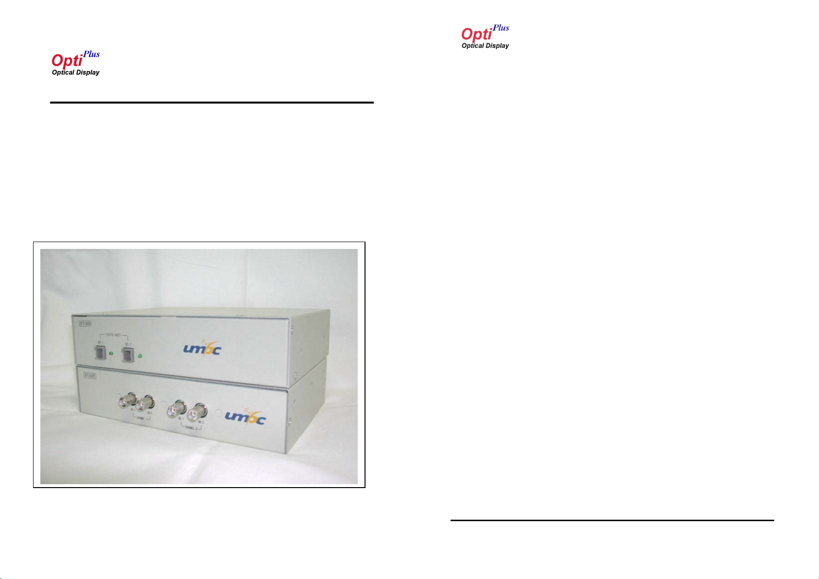
Picture of DFS1000 Series Model
OptiPlus,Inc. 2 / 16
DFS1000 Series
FMextenderTM
Table of Contents
Chapter 1: Introduction
1.1 About This Manual .......................................................................................7
DFS1000 Series
FMextenderTM
Precautions
WARING
1.2 Introduction ..................................................................................................7
Chapter 2: Audio converter system Descriptions
2.1 Feature Summary .......................................................................................8
2.2 Identification of control ...............................................................................8
2.3 Port Definition Summary .............................................................................10
2.4 Electrical Characteristics .............................................................................10
2.5 Physical Dimension ....................................................................................11
Chapter 3: Functional and Interfacing Descriptions
3.1 Feature Summary .......................................................................................12
3.2 Identification of control ...............................................................................13
3.3 Port Definition Summary .............................................................................14
3.4 Electrical Characteristics .............................................................................14
3.5 Physical Dimension ....................................................................................15
DO not dismantle the housing or modify the module
Dismantling the case or modifying the module may result in electrical shock or burn.
Refer all servicing to qualified service personnel
Do not attempt to service this product yourself as opening or removing case may
expose you to dangerous voltage or other hazards.
Keep the away from liquids
Spillage into the housing may result in fire, electrical shock, or equipment damage. If
an object or liquid falls/spills into the housing, unplug the module immediately. Have
the module checked by a qualified service engineer before using it again.
Do not touch the powered DFS1000R and DFS1000T at the same time.
This module is designed for long distance connection, so the DFS1000R and
DFS1000T are isolated electrically. Touching the powered transmitter and powered
receiver at the same time may result in electrical sock.
Do not touch the module with wet hands
OptiPlus,Inc. 3 / 16
Touching the housing and plug with wet hands is dangerous and can cause electrical shock.
OptiPlus,Inc. 4 / 16

DFS1000 Series
FMextenderTM
Safety and EMI
DFS1000 Series
FMextenderTM
Warranty
Operation is subject to the following two conditions:
(1) This device may not cause interference, and
(2) This device must accept any interference, including interference that may
cause undesired operation of the device.
NOTE: This equipment has been tested and found to comply with the limits for a
Class B digital device, pursuant to Part 15 of the FCC Rules. These limits are
designed to provide reasonable protection against harmful interference in a
residential installation. This equipment generates uses and can radiate radio
frequency energy and, if not installed and used in accordance with the instructions,
may cause harmful interference to radio communications. However, there is no
guarantee that interference will not occur in a particular installation. If this equipment
does cause harmful interference to radio or television reception, which can be
determined by turning the equipment off and on, the user is encouraged to try to
correct the interference by one or more of the following measures:
Reorient or relocate the receiving antenna.
Increase the separation between the equipment and receiver.
Connect the equipment into an outlet on a circuit different from that to which
the receiver is connected.
Consult the dealer or an experienced radio/TV technician for help.
CAUTION: Changes or modifications not expressly approved by the party
responsible for compliance could void the user's authority to operate the equipment.
1(One) Year Warranty
Warranty Limitation and Exclusion
warranty if the product has been damaged due to abuse, misuse, neglect,
accident, unusual physical or electrical stress, unauthorized modifications,
tampering, alterations, or service other then by OptiPlus or its authorized agents,
causes other then from ordinary use or failure to properly use the product in the
application for which sad product is intended,
OptiPlus shall have no further obligation under the foregoing limited
Professional Installation:
These systems cannot be sold retail to the general public or by mail order. It is sold
to dealers and professionally installed.
Installation of FM transmitter antenna shall be done by the authorized personal that
are trained and qualified.
Installation must be controlled
Installed by licensed professionals (the system sold to dealer who hire
installers)
Installation requires special training (special programming acess to
keypad, field strength measurements made)
The FM transmitter and its antenna(s) must not be co-located or
operating in conjunction with any other antenna or transmitter
OptiPlus,Inc. 5 / 16
OptiPlus,Inc. 6 / 16

DFS1000 Series
FMextenderTM
Chapter 1 Introduction
DFS1000 Series
FMextenderTM
Chapter 2 Audio converter system Descriptions
1.1 About This Manual
This manual is part of basic Model guide reference documents that provides
information necessary to incorporate the FMextender™ DFS1000 series digital audio
interface FM transmitter and receiver for high speed data transmission interface
controller system. And this document covers spec of the FMextender.
The manual will be updated periodically to include latest component
revisions and respective specification changes. Please contact OptiPlus to obtain
information on how to support all of OPI’s optical display interface.
1.2 Introduction
The FMextender
transmitter communication interface for audio applications. The interface extends
the base technology of SPDIF audio and FM radio to provide a specification more
TM
audio converter and FM transmitter are FM radio
2.1 Feature Summary
The DFS1000R System is a complete analog-to-digital converter for
digital audio systems. It performs sampling, analog to digital conversion, and anti-
alias filtering, generating 24-bit values for both left and right inputs in serial form at
sample rates up to 200 kHz per channel.
The DFS1000R System uses a 5th-order, multi-bit Delta-Sigma modulator followed
by digital filtering and decimation, which removes the need for an external anti-alias
filter. The DFS1000R is ideal for audio systems requiring wide dynamic range,
negligible distortion and low noise, such as set-top boxes, DVD-karaoke players,
DVD recorders, A/V receivers, and automotive applications.
2.2 Identification of control
Audio Working LEC Ch1, Ch2
useful for audio applications.
OptiPlus,Inc. 7 / 16
Digital Audio Out Ch1,Ch2
Figure 2.2.1 Picture of Front Side
OptiPlus,Inc. 8 / 16

DFS1000 Series
A
A
FMextenderTM
System On/Off Switch
DFS1000 Series
FMextenderTM
2.3 Port Definition Summary
Parameter Specification
AC Power Connector
Analog Stereo Audio Input Port
System Power Fuse
Figure 2.2.2 Picture of Rear Side
System
Ground
C Hot
Figure 2.2.3 Picture of Power Inlet
C Natural
Audio Input Port
Audio Output Port
Table 2-1 In / Out Port Configuration
Analog Max 1.0Vp-p Stereo Input Port
Digital Serial out 2Port
2.4 Electrical Characteristics
Parameter Min. Typ . Max. Unit
Input Supply Voltage
Power Dissipation
Storage Temperature
Operating Temperature
Humidity
Support Distance(Output)
AC90 AC260 V
-65 +150 °C
-40 +85 °C
10 80 %
1 50 m
OptiPlus,Inc. 9 / 16
OptiPlus,Inc. 10 / 16

DFS1000 Series
FMextenderTM
2.5 Physical Dimensions
DFS1000 Series
FMextenderTM
Chapter 3 Audio FM Transmitter system Descriptions
The DFS1000R converter contains printed circuit boards mounted with
electronic components and analog audio -to-digital audio logic. The physical
dimensions are shown in the diagram below and depict the expected final
dimensions for the conversion box.
AUDIO INPUT
AUDIO INPUT
LEFT
RIGHT
52mm
52mm
RIGHT
LEFT
224mm
224mm
FUSE
FUSE
152mm
152mm
On/Off
On/Off
POWER
POWER
3.1 Feature Summary
Complete S/PDIF-Compatible Receiver
32 kHz to 192 kHz Sample Frequency Range
Low-Jitter Clock Recovery
On-Chip Channel Status Data Buffer Memories
Auto-Detection of Compressed Audio Input Streams
Carrier Frequency : Ch1 : 88.1MHz / 88.5MHz , Ch2 : 88.1MHz / 88.5MHz
The DFS100T System is converter for FM Broadcasting.
This system is a receives and decodes one of 1 stereo pairs of digital audio
data according to the IEC60958, S/PDIF, EIAJ CP1201, or AES3 interface
standards. The DFS100T System has serial digital audio input port and
comprehensive control ability through a selectable control port in Hardware
Mode.
A low-jitter clock recovery mechanism yields a very clean recovered clock
from the incoming AES3 stream.
Stand-alone operation allows systems with no microcontroller to operate the
DFS100T System with dedicated output port for FM Broadcasting.
DIGITAL AUDIO
DIGITAL AUDIO
Out 2
Out 1
Out 1
Figure 2.5.1 . DFS1000R Physical Dimension
OptiPlus,Inc. 11 / 16
Out 2
DFS1000R
DFS1000R
OptiPlus,Inc. 12 / 16

DFS1000 Series
FMextenderTM
3.2 Identification of control
ANT Connector Ch1, Ch2
Figure 3.2.1 Picture of Front Side
DFS1000 Series
FMextenderTM
3.3 Port Definition Summary
Parameter Specification
Audio Input Port Digital Serial Input Port
Audio Output Port Digital Serial out 2Port
Channel Frequency
Carrier Frequency
Table 2-1 In / Out Port Configuration
PLL Synthesizer System
Support simultaneously 2Ch
Ch1 : 88.1MHz / 88.5MHz
Ch2 : 88.1MHz / 88.5MHz
3.4 Electrical Characteristics
System On/Off Switch
AC Power Connector
System Power Fuse
Figure 3.2.2 Picture of Rear Side
OptiPlus,Inc. 13 / 16
Digital Audio Output Port
Digital Audio Input Port
Parameter Min. Typ . Max. Unit
Input Supply Voltage
Power Dissipation
Storage Temperature
Operating Temperature
Humidity
Support Distance(Output)
AC90 AC260 V
-65 +150 °C
-40 +85 °C
10 80 %
1 50 m
OptiPlus,Inc. 14 / 16

DFS1000 Series
FMextenderTM
3.5 Physical Dimensions
DFS1000 Series
FMextenderTM
Support
The DFS1000T converter contains printed circuit boards mounted with
electronic components and DIGITAL AUDIO -to- FM transmitter logic. The physical
dimensions are shown in the diagram below and depict the expected final
dimensions for the conversion box.
224mm
224mm
Fuse
Fuse
Fuse
On/Off
On/Off
On/Off
POWER
POWER
POWER
52mm
52mm
152mm
152mm
DIGITAL AUDIO
DIGITAL AUDIO
DIGITAL AUDIO
OUT
OUT
OUT
IN
IN
IN
Address : #1112 Sunil Technopia B’d
440 Sangdaewon dong, Jungwon gu, Seongnam city, Gyeonggi do,
KOREA 462 – 120
TEL : 82-31-777-3570, FAX : 82-31-777-3573
Home Page : www.optiplus.co.kr
Support : support@optiplus.co.kr
88.1 88.5
88.1 88.5
88.1 88.5
CHANNEL 1
CHANNEL 1
CHANNEL 1
CHANNEL 2
CHANNEL 2
CHANNEL 2
Figure 3.5.1 . DFS1000T Physical Dimension
OptiPlus,Inc. 15 / 16
DFS1000T
DFS1000T
88.588.1
88.588.1
88.588.1
DFS1000T
OptiPlus,Inc. 16 / 16
 Loading...