

Option Wireless Technology CG0114, CloudGate LTE WW, CloudGate 3G EMEA, CG0112 User Manual

User guide
CloudGate LTE WW
(CG0114)

Table Of Content
1. CloudGate LTE WW (CG0114) ............................................................................................... 3
1.1. Main Board
......................................................................................................................... 5
1.2. Front & Back View
............................................................................................................... 7
1.3. LED Indicators
.................................................................................................................... 10
1.4. Ethernet Interface
............................................................................................................. 13
1.5. RF & Antennas Specs
........................................................................................................ 15
1.5.1. Antenna Specs
.............................................................................................................. 19
1.5.2. Active GPS
.................................................................................................................... 21
1.6. Power Requirements
......................................................................................................... 23
1.6.1. Internal Power Circuits
.................................................................................................... 26
1.7. SIM Card Interface
............................................................................................................ 29
1.8. Reset Button
...................................................................................................................... 30
1.9. Mechanical Drawings
....................................................................................................... 31
1.9.1. IP-65 Requirements
......................................................................................................... 33
1.10. Environmental Specs
....................................................................................................... 35
1.11. Shock resistance
............................................................................................................. 36
1.12. Railway
........................................................................................................................... 37
1.13. Certifications & Approvals
............................................................................................... 38
1.14. Hazardous Locations
....................................................................................................... 45
Last updated on 29/11/2016
CloudGate LTE WW
Model: CG0114
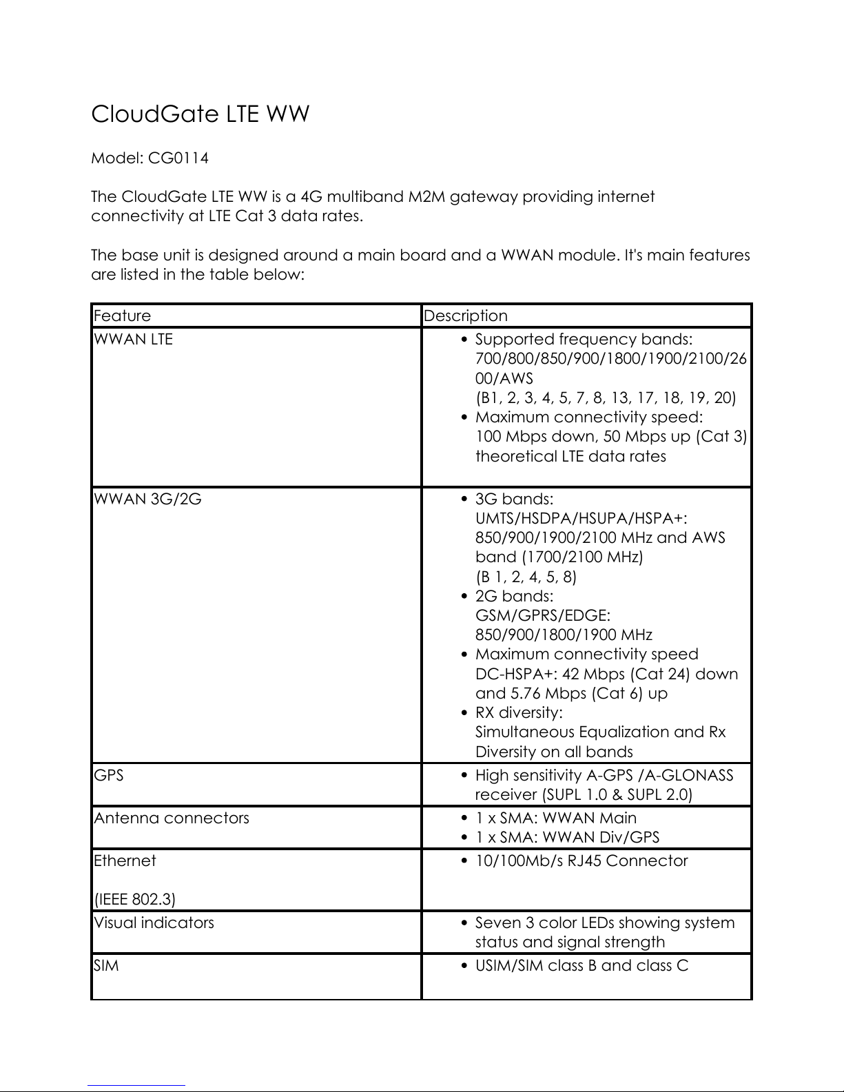
The CloudGate LTE WW is a 4G multiband M2M gateway providing internet
connectivity at LTE Cat 3 data rates.
The base unit is designed around a main board and a WWAN module. It's main features
are listed in the table below:
Feature Description
WWAN LTE Supported frequency bands:
700/800/850/900/1800/1900/2100/26
00/AWS
(B1, 2, 3, 4, 5, 7, 8, 13, 17, 18, 19, 20)
Maximum connectivity speed:
100 Mbps down, 50 Mbps up (Cat 3)
theoretical LTE data rates
WWAN 3G/2G 3G bands:
UMTS/HSDPA/HSUPA/HSPA+:
850/900/1900/2100 MHz and AWS
band (1700/2100 MHz)
(B 1, 2, 4, 5, 8)
2G bands:
GSM/GPRS/EDGE:
850/900/1800/1900 MHz
Maximum connectivity speed
DC-HSPA+: 42 Mbps (Cat 24) down
and 5.76 Mbps (Cat 6) up
RX diversity:
Simultaneous Equalization and Rx
Diversity on all bands
GPS High sensitivity A-GPS /A-GLONASS
receiver (SUPL 1.0 & SUPL 2.0)
Antenna connectors 1 x SMA: WWAN Main
1 x SMA: WWAN Div/GPS
Ethernet
(IEEE 802.3)
10/100Mb/s RJ45 Connector
Visual indicators Seven 3 color LEDs showing system
status and signal strength
SIM USIM/SIM class B and class C
3
Feature Description
MicroSD card reader For additional storage (FAT32).
Located underneath the Cellular
modem PCB inside the CloudGate
LTE WW.
Power input DC input voltage: 9-33 V DC
Connector type: Micro-Fit 3.0™,
Dual row, 4 circuits
Expansion Card Slots Two expansion card slots (one at
the front and one at the back side
of the device)
Expansion boards for I/O functions,
such as Serial, USB, GPIO, WLAN,
Accelerometer, etc.
Metal case Aluminum housing
Dimensions: 115 x 105 x 45 mm
(excluding antenna connectors)
Weight: 304 g
Mounting: bulkhead - 6 x M4
mounting holes or DIN rail with
adapter
Environmentals Operating temperature: -30°C to
70°C (*)
Storage temperature: -40°C to 85°C
Humidity operational: 5% - 95% non
condensing
Certification CE, FCC, IC, PTCRB
Standard compliance ROHS, Reach
CloudGate Universe Device can be configured OTA
using CloudGate Universe
(*) See Safety Warning in the Environmental Specifications section
A more detailed hardware description can be found in the corresponding subsections.
A datasheet of the CloudGate LTE WW can be found here.
The CloudGate LTE WW has two expansion card slots that allow to insert a variety of
expansion cards.
Powered by TCPDF (www.tcpdf.org)
4
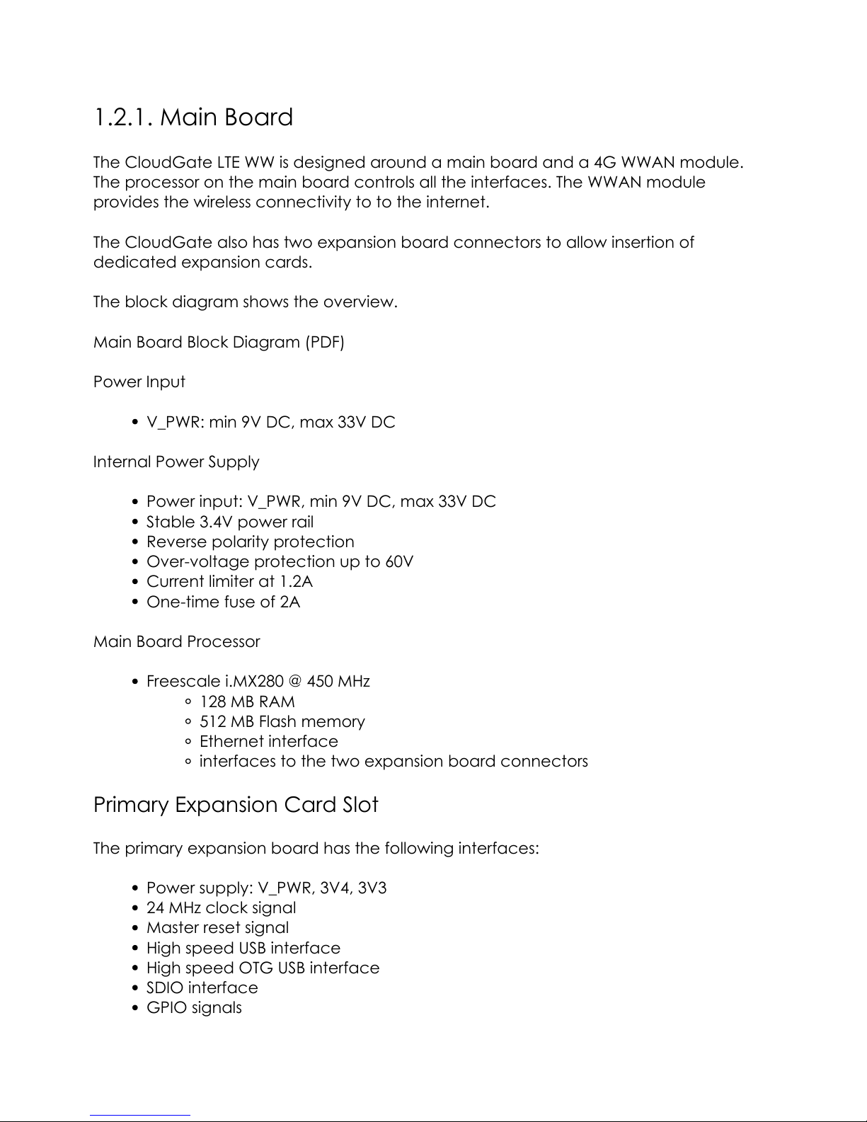
1.2.1. Main Board
The CloudGate LTE WW is designed around a main board and a 4G WWAN module.
The processor on the main board controls all the interfaces. The WWAN module
provides the wireless connectivity to to the internet.
The CloudGate also has two expansion board connectors to allow insertion of
dedicated expansion cards.
The block diagram shows the overview.
Main Board Block Diagram (PDF)
Power Input
V_PWR: min 9V DC, max 33V DC
Internal Power Supply
Power input: V_PWR, min 9V DC, max 33V DC
Stable 3.4V power rail
Reverse polarity protection
Over-voltage protection up to 60V
Current limiter at 1.2A
One-time fuse of 2A
Main Board Processor
Freescale i.MX280 @ 450 MHz
128 MB RAM
512 MB Flash memory
Ethernet interface
interfaces to the two expansion board connectors
Primary Expansion Card Slot
The primary expansion board has the following interfaces:
Power supply: V_PWR, 3V4, 3V3
24 MHz clock signal
Master reset signal
High speed USB interface
High speed OTG USB interface
SDIO interface
GPIO signals
5
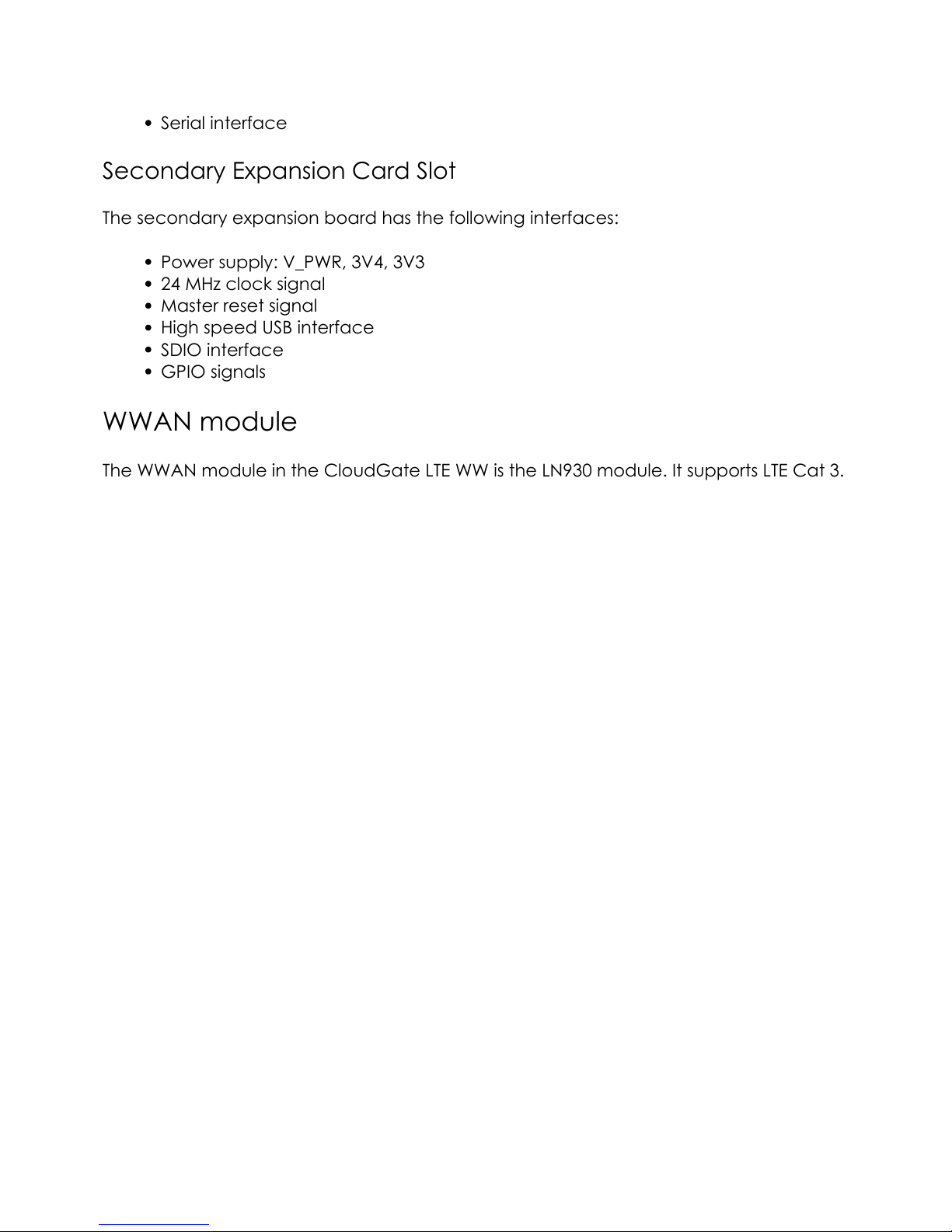
Serial interface
Secondary Expansion Card Slot
The secondary expansion board has the following interfaces:
Power supply: V_PWR, 3V4, 3V3
24 MHz clock signal
Master reset signal
High speed USB interface
SDIO interface
GPIO signals
WWAN module
The WWAN module in the CloudGate LTE WW is the LN930 module. It supports LTE Cat 3.
Powered by TCPDF (www.tcpdf.org)
6

Front and Back View
The CloudGate Base Unit is assembled in the top half of the device. The bottom half is
available to insert expansion cards.
The front and back side of the CloudGate housing are closed by means of metal
panels that are secured with Torx T6 screws.
The top panels are designed by Option and cannot be changed, since they provide
the interfaces of the base unit. The bottom panels can be customized to match the
external interfaces of the expansion card.
Front View
Connectors and LED indicators on the top front panel
On the front side of the device we can see the following connectors:
1 WWAN Diversity and GPS
antenna connector
SMA-female
2 Ethernet port 10/100 Mbps RJ-45
3 WWAN Main antenna
connector
SMA-female
4 Torx T6 screws -
7

A detailed description of the LEDs is given in the section about the LED Indicators.
Bottom Front Panel
The bottom front panel covers the front expansion slot and has to be removed when
installing a Primary Expansion Card.
Option provides a custom panel for the following primary expansion cards:
Low Cost Serial Card
Industrial Serial Card
Ethernet Switch
Ethernet Switch with PoE
Telematics Card
Breadboard Card
Back View
Connector and button on the top back panel
1 Power connector 9-33 VDC
Micro-Fit 3.0, dual
row, 4 circuits
2 Reset button The explanation on
how to use the reset
button is explained
here
8
The functionality of the button is explained in the section about the Reset button
Behind the top back panel there is a socket for insertion of a SIM card.
Please also refer to the section about the SIM Card Interface for more details.
Bottom Back Panel
The bottom back panel covers the back expansion slot and has to be removed when
installing a Secondary Expansion Card.
Option provides a custom panel for the following secondary expansion cards:
WLAN Expansion Card
WLAN Access Point Card
Powered by TCPDF (www.tcpdf.org)
9
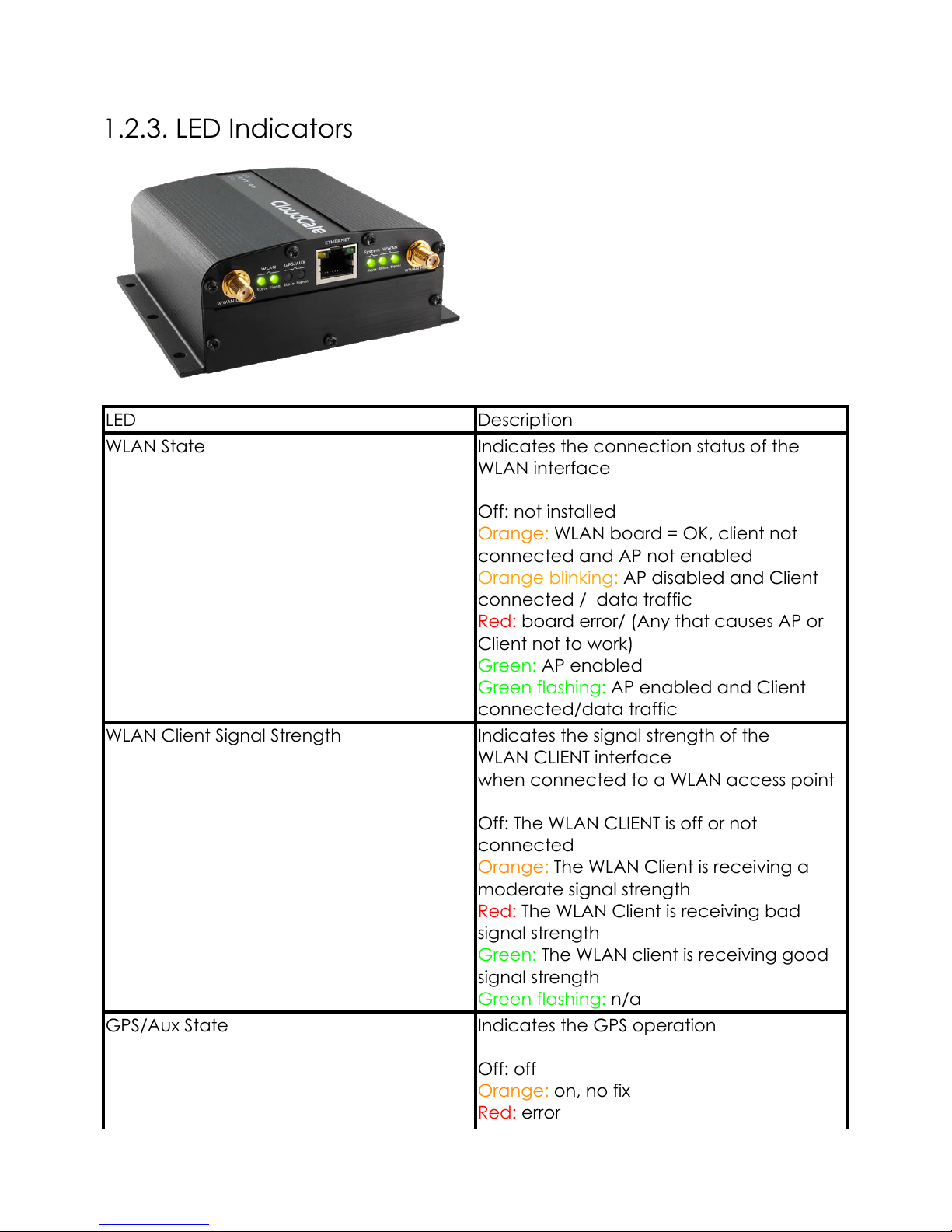
1.2.3. LED Indicators
LED Description
WLAN State Indicates the connection status of the
WLAN interface
Off: not installed
Orange: WLAN board = OK, client not
connected and AP not enabled
Orange blinking: AP disabled and Client
connected / data traffic
Red: board error/ (Any that causes AP or
Client not to work)
Green: AP enabled
Green flashing: AP enabled and Client
connected/data traffic
WLAN Client Signal Strength Indicates the signal strength of the
WLAN CLIENT interface
when connected to a WLAN access point
Off: The WLAN CLIENT is off or not
connected
Orange: The WLAN Client is receiving a
moderate signal strength
Red: The WLAN Client is receiving bad
signal strength
Green: The WLAN client is receiving good
signal strength
Green flashing: n/a
GPS/Aux State Indicates the GPS operation
Off: off
Orange: on, no fix
Red: error
10

LED Description
Green: on, has fix
Green flashing: n/a
GPS/Aux signal strength Indicates the signal strength of the GPS
Off: no signal
Orange: moderate GPS signal
Red: bad GPS signal
Green: good GPS signal
Green flashing: n/a
System State Indicates successful power on and device
readiness
Off: no power
Orange: booting
Red: error
Green: on
Green flashing: n/a
WWAN State Indicates 3G/4G interface availability and
use
Off: no power or not connected
Orange: on, not connected
Red: WWAN error
Green: on, connected
Green flashing: data traffic
WWAN Signal Strength Indicates 3G/4G interface signal strength
Off: no power or not connected
Red: bad signal strength
< -111dbm when connected to 4G
< -104dBm when connected to 3G
Orange: moderate signal strength
>= -111dbm & < -94dbm when connected
to 4G
>= -104dbm & < -94dbm when connected
to 3G
Green: good signal strength (>= -94dbm)
Special LED functions:
During a software download from CloudGate Universe
When the CloudGate is downloading new firmware from the CloudGate Universe the
LED behaviour is different compared to normal behaviour. In this situation the LEDs are
11
moving fast from left to right and back. The colors of the LEDs indicate the next:
Orange: A new firmware is being downloaded
Green: The download was successful. (This will be followed by a reset of the
CloudGate)
Red: The download was not successful.
During the bootup process
When the CloudGate is booting up, the System State LED behaviour is different
compared to normal behaviour. In this situation the System State LED flashes red and
orange. This process is expected behavior and can take up to a minute.
Please not that this only applies on CloudGate devices with a '2' as the third digit in the
serial number, f.e. MJ2xxxxxxx. CloudGate devices with a '1' will show their System State
LED solid orange during the early boot process.
Powered by TCPDF (www.tcpdf.org)
12

1.2.4. Ethernet Interface
This section describes the Ethernet interface on the CloudGate main board.
Ethernet Interface
RJ-45 receptacle tab on top
10/100 Mbps
100BASE-TX
Auto-MDIX
Pinout
Yellow LED:
Active when operating speed is 100 Mbps
Inactive when operating speed is 10 Mbps or when not connected
Green LED:
Active when valid links are detected
Blinks when activity is detected
Inactive when not connected
Pin # Function
1 TX/RX+
2 TX/RX-
3 RX/TX+
4 Not used
13
Pin # Function
5 Not used
6 RX/TX-
7 Not used
8 Not used
IMPORTANT: The auto-MDIX feature is always activated on the CloudGate. This feature
automatically detects the required cable connection type (straight or crossed), and
configures the connection appropriately, removing the need for crossover cables.
In order for auto-MDIX to work correctly, auto-negotiation (auto speed and auto
duplex) must be enabled on both sides of the link. Note that auto negotiation is always
active on the CloudGate.
WAN/LAN Switchover Feature
The WAN/LAN switchover feature is a mechanism to maximize the internet connectivity
via the Ethernet port.
The description of the related configuration parameters and the switchover mechanism
itself can be found in the Ethernet Tab section of the CloudGate Setup Guide.
Powered by TCPDF (www.tcpdf.org)
14
 Loading...