

Page 1

GlobeSurfer 3G
version 3.15.4 R2H
Reference Manual
Page 2

Copyright © 2005, Option
All information about Option GlobeSurfer 3G may change without prior notice.
Information published in this user guide is accurate at the time of publication.
Although all security precautions were taken during the creation of this user guide
Option is not liable toward persons or organizations for losses or damages caused
either directly or indirectly due to instructions contained in this user guide.
All brands and registered brands are property of their respective owners. Services may
be changed, added, or deleted. For the newest firmware version of your Globesurfer
3G, visit www.option.com
Questions and answers regarding the GlobeSurfer 3G can be found on our Support
website:
http://support.option.com/support/faq.php
Technical questions can be posted after registering through our online Support Web
Form:
http://support.option.com/support/newticket.php
For registering please go to:
http://support.option.com/support/register.php
DOC-UM--12-2005
December, 2005
i
Page 3

Contents
Table of Contents ii
1 Introduction to GlobeSurfer 3G 1
1.1 About This Manual . . . . . . . . . . . . . . . . . . . . . . . . . . 2
1.2 Basic Setup . . . . . . . . . . . . . . . . . . . . . . . . . . . . . . . 3
1.3 Step 1 - Setting up LAN and WAN Connections . . . . . . . . . 3
1.3.1 LAN Connection . . . . . . . . . . . . . . . . . . . . . . . 3
1.3.2 WAN Connection . . . . . . . . . . . . . . . . . . . . . . . 4
1.4 Step 2 - PC Network Configuration . . . . . . . . . . . . . . . . . 4
1.4.1 Windows XP . . . . . . . . . . . . . . . . . . . . . . . . . 5
1.4.2 Windows 2000/98/Me . . . . . . . . . . . . . . . . . . . . 5
1.5 Step 3 - GlobeSurfer 3G Quick Setup . . . . . . . . . . . . . . . . 6
1.5.1 UMTS Setup . . . . . . . . . . . . . . . . . . . . . . . . . . 7
1.5.2 Wireless Setup . . . . . . . . . . . . . . . . . . . . . . . . . 8
1.5.2.1 Encryption . . . . . . . . . . . . . . . . . . . . . 8
1.5.3 Firewall Setup . . . . . . . . . . . . . . . . . . . . . . . . . 9
1.6 Additional Network Configuration . . . . . . . . . . . . . . . . . 9
1.7 Adding Computers to Your Network . . . . . . . . . . . . . . . . 10
2 GlobeSurfer 3G Management Console 11
2.1 Accessing the GlobeSurfer 3G Management Console . . . . . . . 11
2.2 Left Sidebar . . . . . . . . . . . . . . . . . . . . . . . . . . . . . . 12
2.3 UMTS Connection Status . . . . . . . . . . . . . . . . . . . . . . . 13
2.4 Getting Help . . . . . . . . . . . . . . . . . . . . . . . . . . . . . . 14
2.5 Managing Tables . . . . . . . . . . . . . . . . . . . . . . . . . . . 14
3 SMS Manager 15
3.1 Reading an SMS . . . . . . . . . . . . . . . . . . . . . . . . . . . . 15
3.2 Creating an SMS . . . . . . . . . . . . . . . . . . . . . . . . . . . . 16
3.2.1 Sent folder . . . . . . . . . . . . . . . . . . . . . . . . . . . 17
3.3 Archiving an SMS . . . . . . . . . . . . . . . . . . . . . . . . . . . 17
3.4 SMS Templates . . . . . . . . . . . . . . . . . . . . . . . . . . . . 17
3.5 SMS Settings . . . . . . . . . . . . . . . . . . . . . . . . . . . . . . 18
4 Network Connections 19
4.1 WAN UMTS Connection . . . . . . . . . . . . . . . . . . . . . . . 21
4.1.1 General Network Connection Parameters . . . . . . . . . 22
4.1.2 UMTS . . . . . . . . . . . . . . . . . . . . . . . . . . . . . 22
4.1.3 PPP Authentication . . . . . . . . . . . . . . . . . . . . . . 23
4.1.4 Internet Protocol Settings . . . . . . . . . . . . . . . . . . 24
ii
Page 4

4.1.5 DNS Server . . . . . . . . . . . . . . . . . . . . . . . . . . 24
4.1.6 Routing . . . . . . . . . . . . . . . . . . . . . . . . . . . . 25
4.1.7 Additional Network Connection Settings . . . . . . . . . 26
4.2 LAN Ethernet Connection . . . . . . . . . . . . . . . . . . . . . . 27
4.2.1 General Network Connection Parameters . . . . . . . . . 27
4.2.2 Internet Protocol . . . . . . . . . . . . . . . . . . . . . . . 28
4.2.3 DNS Server . . . . . . . . . . . . . . . . . . . . . . . . . . 29
4.2.4 DHCP . . . . . . . . . . . . . . . . . . . . . . . . . . . . . 29
4.2.5 Routing . . . . . . . . . . . . . . . . . . . . . . . . . . . . 31
4.2.6 Additional Network Connection Settings . . . . . . . . . 32
4.3 LAN Wireless Connection . . . . . . . . . . . . . . . . . . . . . . 33
4.3.1 Configuring Your Wireless Network . . . . . . . . . . . . 33
4.3.1.1 Configuring your GlobeSurfer 3G Wireless Con-
nection . . . . . . . . . . . . . . . . . . . . . . . 33
4.3.1.2 Configuring Your Wireless Windows XP Client 34
4.3.2 Securing Your Wireless Network . . . . . . . . . . . . . . 39
4.3.2.1 Securing Your Wireless Network with WPA . . 39
4.3.2.2 Connecting a Wireless Windows XP Client to
the Secured Wireless Network . . . . . . . . . . 41
4.3.3 Advanced Wireless Connection Settings . . . . . . . . . . 47
4.3.3.1 General Network Connection Parameters . . . 47
4.3.3.2 Wireless Access Point . . . . . . . . . . . . . . . 47
4.3.3.3 MAC filtering settings . . . . . . . . . . . . . . . 48
4.3.3.4 Advanced Wireless Options . . . . . . . . . . . 48
4.3.3.5 Wireless Security . . . . . . . . . . . . . . . . . 49
4.3.3.6 Internet Protocol . . . . . . . . . . . . . . . . . . 50
4.3.3.7 Additional Network Connection Settings . . . . 51
4.4 LAN Bridge Connection . . . . . . . . . . . . . . . . . . . . . . . 52
4.4.1 General Network Connection Parameters . . . . . . . . . 52
4.4.2 Internet Protocol . . . . . . . . . . . . . . . . . . . . . . . 53
4.4.3 Bridge Settings . . . . . . . . . . . . . . . . . . . . . . . . 54
4.4.4 DNS Server . . . . . . . . . . . . . . . . . . . . . . . . . . 54
4.4.5 DHCP . . . . . . . . . . . . . . . . . . . . . . . . . . . . . 55
4.4.6 Routing . . . . . . . . . . . . . . . . . . . . . . . . . . . . 57
4.4.7 Additional Network Connection Settings . . . . . . . . . 57
4.5 VPN PPTP . . . . . . . . . . . . . . . . . . . . . . . . . . . . . . . 59
4.5.1 Creating a PPTP Client Connection . . . . . . . . . . . . 59
4.5.2 Creating a PPTP Server Connection . . . . . . . . . . . . 61
4.5.3 Configuring a PPTP Connection . . . . . . . . . . . . . . 64
4.5.3.1 General . . . . . . . . . . . . . . . . . . . . . . . 64
4.5.3.2 PPP Settings . . . . . . . . . . . . . . . . . . . . 65
4.5.3.3 PPP Authentication . . . . . . . . . . . . . . . . 65
4.5.3.4 PPP Encryption . . . . . . . . . . . . . . . . . . 66
4.5.3.5 Internet Protocol . . . . . . . . . . . . . . . . . . 66
4.5.3.6 DNS Server . . . . . . . . . . . . . . . . . . . . . 67
4.5.3.7 Routing . . . . . . . . . . . . . . . . . . . . . . . 68
4.5.3.8 Internet Connection Firewall . . . . . . . . . . . 69
4.6 VPN L2TP . . . . . . . . . . . . . . . . . . . . . . . . . . . . . . . 70
4.6.1 Creating an L2TP Connection . . . . . . . . . . . . . . . . 70
4.6.2 Configuring an L2TP Connection . . . . . . . . . . . . . . 72
iii
Page 5

4.6.2.1 General . . . . . . . . . . . . . . . . . . . . . . . 72
4.6.2.2 PPP Settings . . . . . . . . . . . . . . . . . . . . 73
4.6.2.3 PPP Authentication . . . . . . . . . . . . . . . . 74
4.6.2.4 PPP Encryption . . . . . . . . . . . . . . . . . . 74
4.6.2.5 PPP Compression . . . . . . . . . . . . . . . . . 75
4.6.2.6 Internet Protocol . . . . . . . . . . . . . . . . . . 75
4.6.2.7 DNS Server . . . . . . . . . . . . . . . . . . . . . 76
4.6.2.8 Routing . . . . . . . . . . . . . . . . . . . . . . . 77
4.6.2.9 Internet Connection Firewall . . . . . . . . . . . 78
4.7 VPN IPsec . . . . . . . . . . . . . . . . . . . . . . . . . . . . . . . 79
4.7.1 IPsec Network-to-Host Scenario Connection . . . . . . . 79
4.7.1.1 Configuring IPsec on GlobeSurfer 3G . . . . . . 79
4.7.1.2 Configuring IPsec on the Windows Host . . . . 82
4.7.2 IPsec Network-to-Network Scenario Connection . . . . . 95
4.7.2.1 Network Configuration . . . . . . . . . . . . . . 95
4.7.2.1.1 LAN Interface Settings . . . . . . . . . 95
4.7.2.2 Network-to-Network with Pre-shared Secrets . 97
5 Security 102
5.1 General Security Level Settings . . . . . . . . . . . . . . . . . . . 104
5.2 Access Control . . . . . . . . . . . . . . . . . . . . . . . . . . . . . 107
5.3 Local Servers (Port Forwarding) . . . . . . . . . . . . . . . . . . . 110
5.4 DMZ Host . . . . . . . . . . . . . . . . . . . . . . . . . . . . . . . 113
5.5 Port Triggering . . . . . . . . . . . . . . . . . . . . . . . . . . . . 114
5.6 Remote Administration . . . . . . . . . . . . . . . . . . . . . . . 117
5.7 IP-Hostname Filtering . . . . . . . . . . . . . . . . . . . . . . . . 119
5.8 Advanced Filtering . . . . . . . . . . . . . . . . . . . . . . . . . . 122
5.8.1 Adding an Advanced Filtering Rule . . . . . . . . . . . . 123
5.9 Security Log . . . . . . . . . . . . . . . . . . . . . . . . . . . . . . 126
5.9.1 Security Log Settings . . . . . . . . . . . . . . . . . . . . . 130
5.10 User-defined Services . . . . . . . . . . . . . . . . . . . . . . . . . 132
5.11 Applying Corporate-Grade Security . . . . . . . . . . . . . . . . 134
6 Advanced 136
6.1 System Settings . . . . . . . . . . . . . . . . . . . . . . . . . . . . 139
6.1.1 System . . . . . . . . . . . . . . . . . . . . . . . . . . . . . 139
6.1.2 GlobeSurfer 3G Management Console Settings . . . . . . 139
6.1.3 Management Application Ports Settings . . . . . . . . . . 139
6.1.4 System Logging Settings . . . . . . . . . . . . . . . . . . . 140
6.1.5 Security Logging Settings . . . . . . . . . . . . . . . . . . 140
6.1.6 Outgoing Mail Server Settings . . . . . . . . . . . . . . . 140
6.1.7 HTTP interception . . . . . . . . . . . . . . . . . . . . . . 140
6.2 DNS Server . . . . . . . . . . . . . . . . . . . . . . . . . . . . . . 141
6.2.1 Viewing and Modifying the DNS Table . . . . . . . . . . 141
6.3 Dynamic DNS . . . . . . . . . . . . . . . . . . . . . . . . . . . . . 143
6.3.1 Using Dynamic DNS . . . . . . . . . . . . . . . . . . . . . 143
6.4 Network Map . . . . . . . . . . . . . . . . . . . . . . . . . . . . . 144
6.5 DHCP . . . . . . . . . . . . . . . . . . . . . . . . . . . . . . . . . . 146
6.5.1 DHCP Server Summary . . . . . . . . . . . . . . . . . . . 146
6.5.2 DHCP Server Settings . . . . . . . . . . . . . . . . . . . . 147
iv
Page 6

6.5.3 DHCP Server Relay Settings . . . . . . . . . . . . . . . . 148
6.5.4 DHCP Connections . . . . . . . . . . . . . . . . . . . . . . 148
6.6 Network Objects . . . . . . . . . . . . . . . . . . . . . . . . . . . 151
6.7 Routing . . . . . . . . . . . . . . . . . . . . . . . . . . . . . . . . . 153
6.7.1 Managing Routing Table Rules . . . . . . . . . . . . . . . 153
6.7.2 Multicasting . . . . . . . . . . . . . . . . . . . . . . . . . . 154
6.8 Managing Users . . . . . . . . . . . . . . . . . . . . . . . . . . . . 155
6.9 Certificates . . . . . . . . . . . . . . . . . . . . . . . . . . . . . . . 157
6.9.1 Digital Certificates . . . . . . . . . . . . . . . . . . . . . . 157
6.9.2 X.509 Certificate Format . . . . . . . . . . . . . . . . . . . 157
6.9.3 Obtaining an X.509 Certificate . . . . . . . . . . . . . . . 158
6.9.4 Registering a CA’s Certificate . . . . . . . . . . . . . . . . 162
6.10 Date and Time . . . . . . . . . . . . . . . . . . . . . . . . . . . . . 163
6.11 Scheduler Rules . . . . . . . . . . . . . . . . . . . . . . . . . . . . 164
6.12 Firmware Upgrade . . . . . . . . . . . . . . . . . . . . . . . . . . 166
6.12.1 Upgrading From a Local Computer . . . . . . . . . . . . 166
6.13 Point-to-Point Tunneling Protocol (PPTP) . . . . . . . . . . . . . 168
6.13.1 Managing Remote Users . . . . . . . . . . . . . . . . . . . 168
6.13.2 Advanced PPTP Server Settings . . . . . . . . . . . . . . 170
6.13.3 Advanced PPTP Client Settings . . . . . . . . . . . . . . . 170
6.14 IP Security (IPsec) . . . . . . . . . . . . . . . . . . . . . . . . . . . 172
6.14.1 Technical Specifications . . . . . . . . . . . . . . . . . . . 172
6.14.2 Basic IPsec Connection Settings . . . . . . . . . . . . . . . 172
6.14.2.1 Key Management . . . . . . . . . . . . . . . . . 173
6.14.2.2 Log Settings . . . . . . . . . . . . . . . . . . . . 174
6.14.3 Advanced IPsec Connection Settings . . . . . . . . . . . . 174
6.15 Universal Plug and Play (UPnP) . . . . . . . . . . . . . . . . . . 177
6.16 Simple Network Management Protocol (SNMP) . . . . . . . . . 178
6.16.1 Configuring GlobeSurfer 3G’s SNMP Agent . . . . . . . 178
6.17 Diagnostics . . . . . . . . . . . . . . . . . . . . . . . . . . . . . . . 179
6.17.1 Diagnosing Network Connectivity . . . . . . . . . . . . . 179
6.18 Advanced Remote Administration . . . . . . . . . . . . . . . . . 180
6.19 SIM Setup . . . . . . . . . . . . . . . . . . . . . . . . . . . . . . . 182
6.20 Unlock Device . . . . . . . . . . . . . . . . . . . . . . . . . . . . . 183
6.21 Restoring Default Settings . . . . . . . . . . . . . . . . . . . . . . 184
6.22 Restart . . . . . . . . . . . . . . . . . . . . . . . . . . . . . . . . . 185
6.23 Technical Information . . . . . . . . . . . . . . . . . . . . . . . . 186
7 System Monitoring 187
7.1 Monitoring Connections . . . . . . . . . . . . . . . . . . . . . . . 188
7.2 Traffic Statistics . . . . . . . . . . . . . . . . . . . . . . . . . . . . 189
7.3 System Log . . . . . . . . . . . . . . . . . . . . . . . . . . . . . . . 190
7.4 System Up Time . . . . . . . . . . . . . . . . . . . . . . . . . . . . 191
A Glossary 192
v
Page 7

List of Acronyms
3G Third Generation (mobile network)
ALG Application-Level Gateway
API Application Programming Interface
APN Access Point Name
CA Certificate Authority
DHCP Dynamic Host Configuration Protocol
DMZ Demilitarized Zone
DNS Domain Name System
DSL Digital Subscriber Line
FTP File Transfer Protocol
HTTP HyperText Transport Protocol
IAD Integrated Access Device
ICMP Internet Control Message Protocol
IGMP Internet Group Multicast Protocol
IP Internet Protocol
IPsec IP Security
LAN Local Area Network
MAC Media Access Control
MTU Maximum Transmission Unit
NAPT Network Address Port Translation
OAM Operations and Maintenance
OEM Original Equipment Manufacturer
PDA Personal Digital Assistant
POP3 Post Office Protocol 3
PPP Point-to-Point Protocol
PPTP Point-to-Point Tunneling Protocol
PUK Pin Unlocking Key
RG Residential Gateway
RIP Routing Information Protocol
SMS Short Message Service
SMSC Short Message Service Center
SIM Security Identity Module
SNMP Simple Network Management Protocol
SPI Stateful Packet Inspection
TCP Transmission Control Protocol
TFTP Trivial File Transfer Protocol
UDP User Datagram Protocol
UMTS Universal Mobile Telephony System
UPnP Universal Plug and Play
vi
Page 8

URL Universal Resource Locator
VPN Virtual Private Network
WAN Wide Area Network
WEP Wireless Encryption Protocol
WLAN Wireless Local Area Network
WPA Wireless Protected Access
vii
Page 9

1
Introduction to GlobeSurfer 3G
Welcome to the third generation wireless network. By combining a wireless
router following the 802.11 b/g WLAN standard with a 3G UMTS Gateway
the GlobeSurfer 3G presents a new style of wireless freedom.
The GlobeSurfer 3G is a 802.11b/g wireless router and Internet gateway that
provides Internet access for homes and small offices over the 3G UMTS network. By connecting laptops and stationary computers with either WLAN or
Ethernet to the GlobeSurfer 3G you will get Internet access with a speed similar
to a fixed DSL connection. And while sharing the wireless Internet connection
you will also be able to share the resources of the local computers connected to
the GlobeSurfer 3G.
GlobeSurfer 3G is easy to install and use. Yet it provides advanced networking functions and security functions that can be configured with a web-based
management interface. Its small attractive design and powerful built-in functionality makes your Internet surfing easy and secure in any location with 3G
access and a power outlet.
Some of the attractive features of the GlobeSurfer 3G:
• WAN - UMTS uplink and downlink
• Small attractive design with informative display
• Sends and receives SMS
• WLAN according to 802.11 b/g for maximum compatibility
• Ethernet connection for stationary computers
• Built-in firewall to protect against hacker attacks
• Wireless LAN Security: WEP, WPA, 802.1x
• VPN (Virtual Private Network): IPsec, PPTP, L2TP
1
Page 10
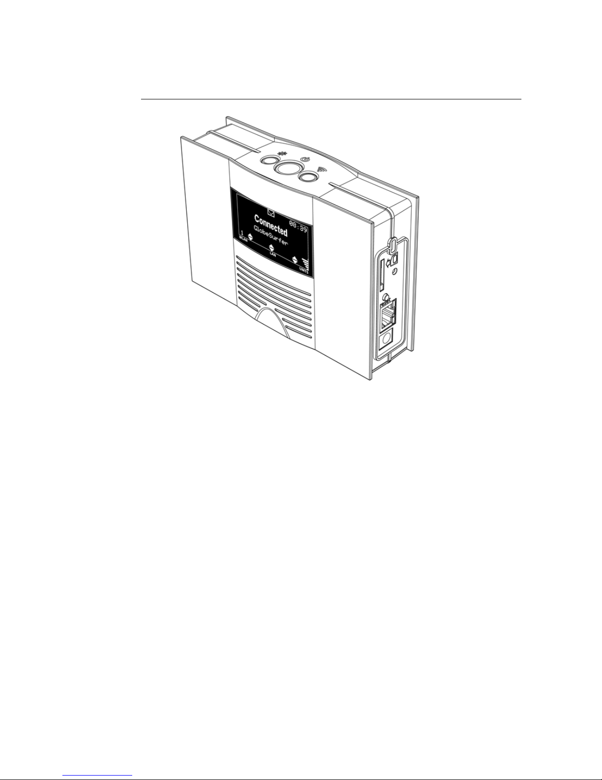
Figure 1.1: The GlobeSurfer 3G
• Web-based management console makes configuration intuitive
• System statistics and monitoring for the advanced users
• Remote upgrade to stay in touch with the future
1.1 About This Manual
This manual describes configuration and operation of the GlobeSurfer 3G. It
is intended as a complement to the GlobeSurfer 3G User Guide to provide reference information for the advanced user of the GlobeSurfer 3G. It is assumed
that the hardware installation of the GlobeSurfer 3G has been done when the
Reference Manual is read.
This version of the manual is valid for GlobeSurfer 3G version 3.15.4 R2H.
Other product versions with customer specific functions not described in this
manual, may be available.
2
Page 11
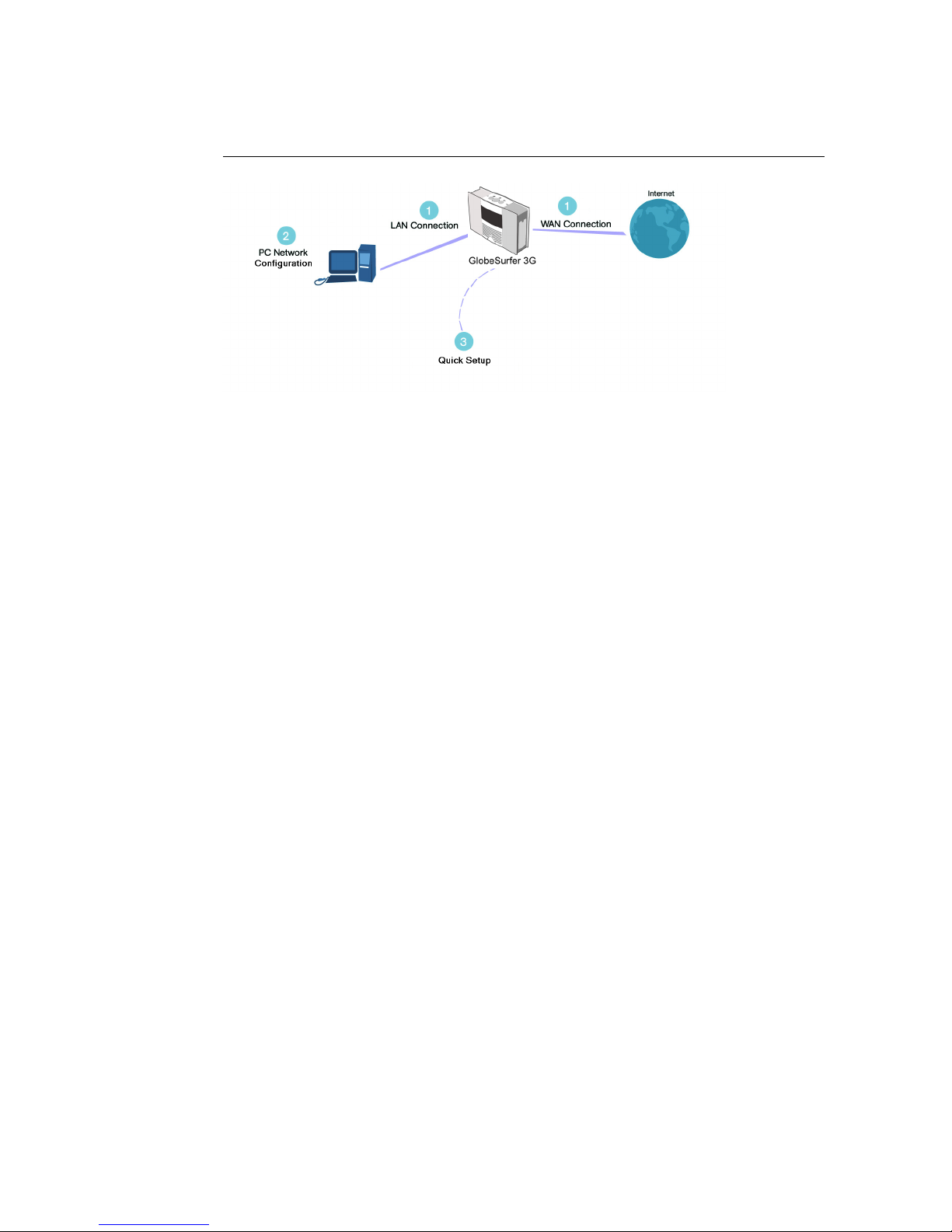
Figure 1.2: Hardware Configuration
1.2 Basic Setup
Connecting your computer or local network to the GlobeSurfer 3G is a simple
procedure, varying slightly depending on your operating system. The setup is
designed to seamlessly integrate GlobeSurfer 3G with your computer or local
network.
The Windows default network settings will in most cases make the setup procedure described below unnecessary. For example, the default DHCP setting
in Windows is client, requiring no further modification.
However, it is advised to follow the setup procedure described below to verify
that all communication parameters are valid and that the physical cable connections are correct.
The basic setup procedure consists of three consecutive configuration steps
(Please refer to figure 1.2):
1. Setting up LAN and WAN connections [1.3]
2. PC network configuration [1.4]
3. GlobeSurfer 3G Quick Setup [1.5]
1.3 Step 1 - Setting up LAN and WAN Connections
1.3.1 LAN Connection
Your computer can connect to the GlobeSurfer 3G either with a fixed cable
connection or with a wireless connection.
If you want to use a fixed connection, connect a standard Ethernet RJ-45 cable
(Category 5) between the LAN socket on the GlobeSurfer 3G and the corresponding Ethernet LAN port of your PC network card. Consult the GlobeSurfer
3G User Guide for more information about the LAN port.
3
Page 12

If you want to use a wireless connection, according to the 802.11 b/g WLAN
standard, follow the instructions from the supplier of your WLAN adapter
card, or your PC if the WLAN adapter is built into the PC.
1.3.2 WAN Connection
Setting up the WAN connection requires that a SIM card is inserted correctly
into the SIM slot of the GlobeSurfer 3G. See the User Guide for instructions on
how to insert the SIM card. With the SIM card in place you configure the WAN
connection through the Quick Setup of the GlobeSurfer 3G (see section 1.5. The
first time you login to the GlobeSurfer 3G you will have to enter a PIN code.
The PIN code is received from your ISP, but normally provided separately from
the SIM card for security reasons.
1.4 Step 2 - PC Network Configuration
The GlobeSurfer 3G provides a DHCP server, which means that each computer
connected to the LAN can obtain its network addresses – IP address and DNS
server IP addresses – automatically from the GlobeSurfer 3G. This is the default setting in Windows and valid in most cases. Alternatively, each network
interface on the LAN PCs can be configured with a statically defined IP address and DNS address. If this is the case you must receive valid addresses
from your network operator and configure your PC and the GlobeSurfer 3G
accordingly. Then refer to section 4.2.
Figure 1.3 displays the TCP/IP Properties dialog box as it appears in Windows
XP. These properties are available on all operating systems but are accessed
slightly differently on each operating system.
4
Page 13

Figure 1.3: IP and DNS Configuration
1.4.1 Windows XP
1. Access Network Connections from the Control Panel.
2. Right-click on the Ethernet connection icon, and select Properties.
3. Under the General tab, select the Internet Protocol (TCP/IP) component,
and click the Properties button.
4. The Internet Protocol (TCP/IP) properties window will be displayed (see
figure 1.3).
(a) Select the Obtain an IP address automatically radio button.
(b) Select the Obtain DNS server address automatically radio button.
(c) Click OK to save the settings.
1.4.2 Windows 2000/98/Me
1. Access Network and Dialing Connections from the Control Panel.
5
Page 14
2. Right-click on the Ethernet connection icon, and select Properties to display the connection’s properties.
3. Select the Internet Protocol (TCP/IP) component, and click the Properties
button.
4. The Internet Protocol (TCP/IP) properties will be displayed.
(a) Select the Obtain an IP address automatically radio button.
(b) Select the Obtain DNS server address automatically radio button.
1.5 Step 3 - GlobeSurfer 3G Quick Setup
The GlobeSurfer 3G management console allows you to control various GlobeSurfer
3G system parameters. The interface is accessed through a web browser:
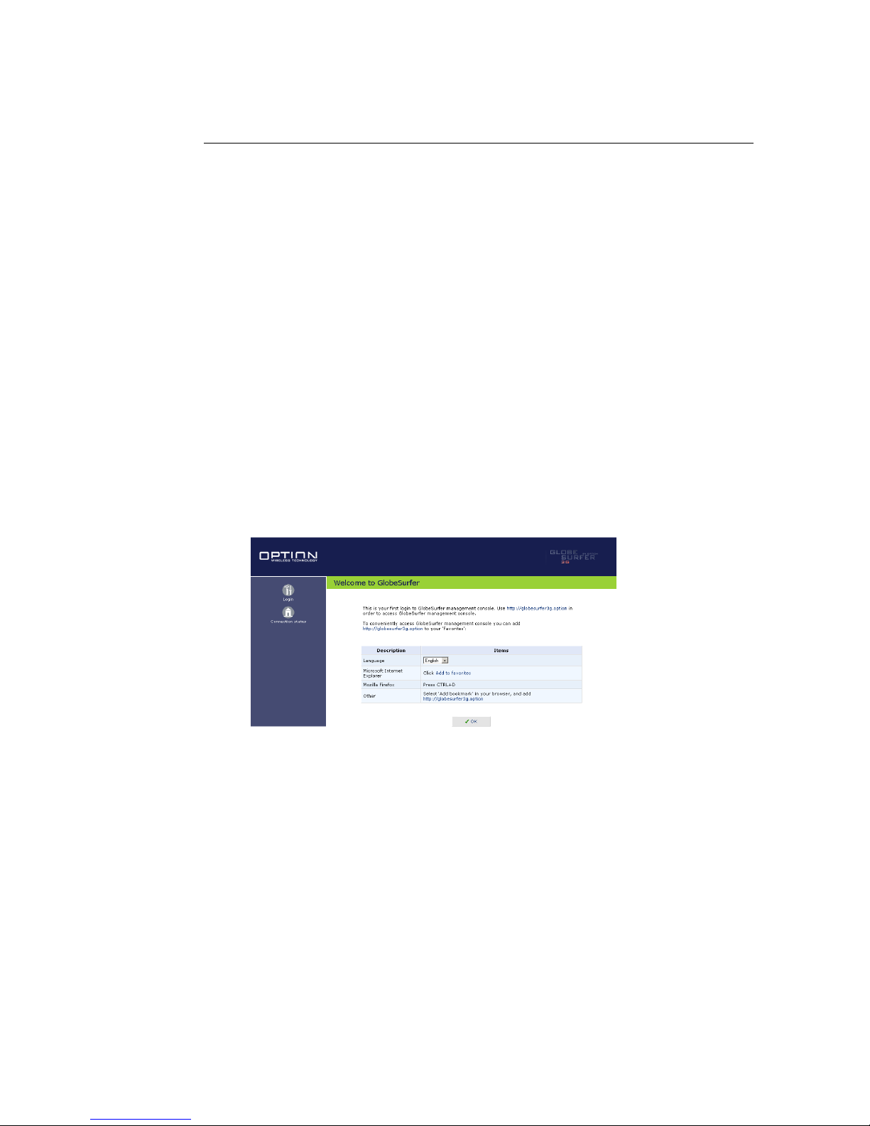
1. Start a web browser on your PC.
2. Enter the address 192.168.1.1 to display the GlobeSurfer 3G management
console. When first logging on to the management console, the welcome
screen will appear (see figure 1.4), enabling you to place a shortcut to this
screen in your Favorites folder. Click OK to continue. The Login Setup
screen will appear (see figure 2.1).
Figure 1.4: Welcome to GlobeSurfer 3G
3. To configure your login settings, enter a user name and password. To
verify correctness retype the password, and click OK to login to the management console. For security reasons it is strongly recommended that
you change the default user name and specify a password. However,
make sure you remember your new user name and password, since this
is the only way you will be able to login to the GlobeSurfer 3G from now
on.
6
Page 15
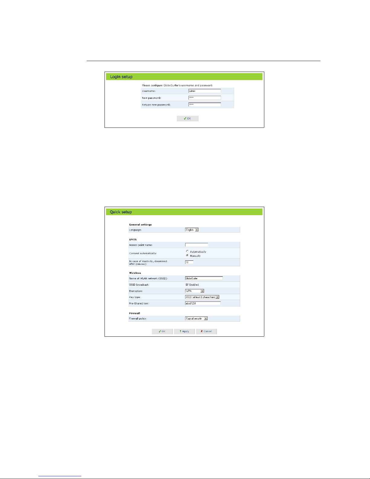
Figure 1.5: Login Settings
4. Quick setup helps you to quickly set the most important settings of your
GlobeSurfer 3G. The Quick setup page is launched automatically when
you log on to GlobeSurfer 3G for the first time (see figure
1.6). Alterna-
tively, click the Quick setup icon on the left sidebar. The following sections
describe the various configuration parameters of Quick setup. Once you
have filled the Quick setup sections as described below, click the OK button to configure your GlobeSurfer 3G.
Figure 1.6: Quick Setup
1.5.1 UMTS Setup
Check or change the following settings on the Quick setup screen to configure
the UMTS connection:
• Access point name: Enter the access point name as provided by your
Internet Service Provider (ISP), or accept the name already set.
7
Page 16

• Connect automatically: To automatically set up a UMTS connection when
data is about to be sent or received, select Automatically. If Manually is selected, you must press the Connect button on the GlobeSurfer 3G each
time a connection is required.
• Inactivity timeout: There is normally no need to change the default value
of 10 minutes. Set it to zero (0) if you don’t want the UMTS connection to
disconnect automatically at all. The maximum value is 1440 minutes (24
h). The inactivity timeout is not affected by incoming traffic.
1.5.2 Wireless Setup
The following settings are the most important to set up for the local Wireless
LAN:
• SSID: The Service Set Identifier (SSID) is the name of the specific wireless network. Enter a name that you want to use as an identifier of your
specific local wireless network (maximum 32 characters).
• SSID broadcast: When this checkbox is set to Enabled the GlobeSurfer 3G
will broadcast the SSID on your wireless network. This will allow unauthorized devices from detecting your SSID and attempting to connect
to your network. De-select the checkbox to disable broadcasting of the
SSID. Disabling SSID broadcast will hide the name of the network from
other wireless devices. This provides a very basic form of security. Other
devices will still be able to connect, provided that they are supplied with
the SSID. A recommendation is to install your wireless network with this
feature enabled and then disable it once you have set up the GlobeSurfer
3G and any wireless clients.
• Encryption: With No encryption selected, anyone with a Wireless PC can
eavesdrop on your network. No encryption should only be used during
installation of your network to simplify the setup procedure. Select WEP
encryption or WPA encryption once your local wireless network has been
set up. See below for instructions on how to set the encryption type.
1.5.2.1 Encryption
The GlobeSurfer 3G supports two types of encryption:
• WEP: Wireless Equivalent Privacy (WEP) is a 64 bit or 128 bit encryption
method with user configurable fixed keys. However, only 40/104 bits are
effectively used.
• WPA: Wi-Fi Protected Access (WPA) is a 256 bit encryption method with
keys that change over time.
Note: WPA provides a higher level of security, provided by its longer key and
dynamic changes made to the key over time. Use WPA with any clients that
support it. If you enable encryption on the GlobeSurfer 3G, you must configure
your wireless PCs to use exactly the same encryption type and keys, otherwise
the devices will not understand each other. The encryption secures the wireless communication between GlobeSurfer 3G and its wireless clients. Enabling
8
Page 17

encryption has no security effect on data transmitted through wired (Ethernet)
connections.
• Configuring WEP:
There are two levels of WEP encryption available, 64 bit and 128 bit. Select the desired level. Enter the pre-shared key in either hexadecimal
(0-9, A-F) format, 10 or 26 characters, or plain text (ASCII) format, 5 or 13
characters.
• Configuring WPA:
With WPA there is only one level of encryption available. Enter the preshared key, either as a 256 bit series of hexadecimal digits (64 characters)
or as a plain text (ASCII) pass-phrase (at least 8 characters).
Note: A plain text string is much easier to remember than hex keys, but it may
be easier to crack. Also note that the ASCII-text format may not be supported
by all wireless devices, since different manufacturers have developed different
ways of converting plain text. If you are experiencing difficulty, the hex key
format is supported by most vendors.
1.5.3 Firewall Setup
The GlobeSurfer 3G firewall has three pre-defined levels of security. As default
the typical security is set, which blocks all traffic that has been initiated by an
external (Internet) source, and allows all traffic that has been initiated from
your local network.
Note: It is the origin of the request, not subsequent responses to this request, that
determines whether the incoming or outgoing traffic is allowed or blocked.
To learn more about how to configure your firewall security parameters, please
refer to Section 5. If you wish to apply corporate-grade security to your network refer to Section 5.11.
1.6 Additional Network Configuration
GlobeSurfer 3G does not require further configuration in order to start working. After the setup described in this chapter, you can immediately start using
the GlobeSurfer 3G to:
• Build a local network by connecting additional PCs and network devices
to the GlobeSurfer 3G.
• Share the Internet connection among multiple users and between all of
the computers connected to your local network.
• Share resources like file servers, printers, etc. between computers in the
local network.
• Control network parameters to, for example, set up Virtual Private Networks, LAN bridges and configure the security settings.
• View network status, traffic statistics, system log and more.
9
Page 18

Advanced users can fully configure and control the GlobeSurfer 3G via the
web-based management console. Chapter 2 serves as an introduction to the
management console; in-depth module-specific information is available throughout chapters 4 – 7.
1.7 Adding Computers to Your Network
Any computers with a 802.11b/g wireless adapter will be able to connect to
the WLAN created with the GlobeSurfer 3G. To connect additional computers
without a wireless adapter to your GlobeSurfer 3G, connect a hub or switch
to the LAN port, and then connect the computers to the hub or switch. Make
sure to configure all computers to automatically obtain a network address as
described above.
10
Page 19

2
GlobeSurfer 3G Management
Console
The GlobeSurfer 3G management console described here allows you to control
various GlobeSurfer 3G system parameters, using a user-friendly graphical interface. The management console includes a quick setup screen, a graphical
network map, network configuration, security configuration, authentication
with multiple-user support, connection monitoring and more.
2.1 Accessing the GlobeSurfer 3G Management Console
To access the management console:
1. Launch a Web-browser on a PC in the LAN or WLAN.
2. Type the IP address of the GlobeSurfer 3G or a name as provided by the
supplier in the address bar (Internet Explorer) or location bar (Netscape
Navigator). The default IP address is 192.168.1.1, and default name is
http://umts-gateway.my-domain.
3. Enter your username and password to log on to the web-based management console. Note: for security reasons, you should change these settings after the initial login as explained in Section 1.5. The default user
name is admin, and the default password is none.
11
Page 20
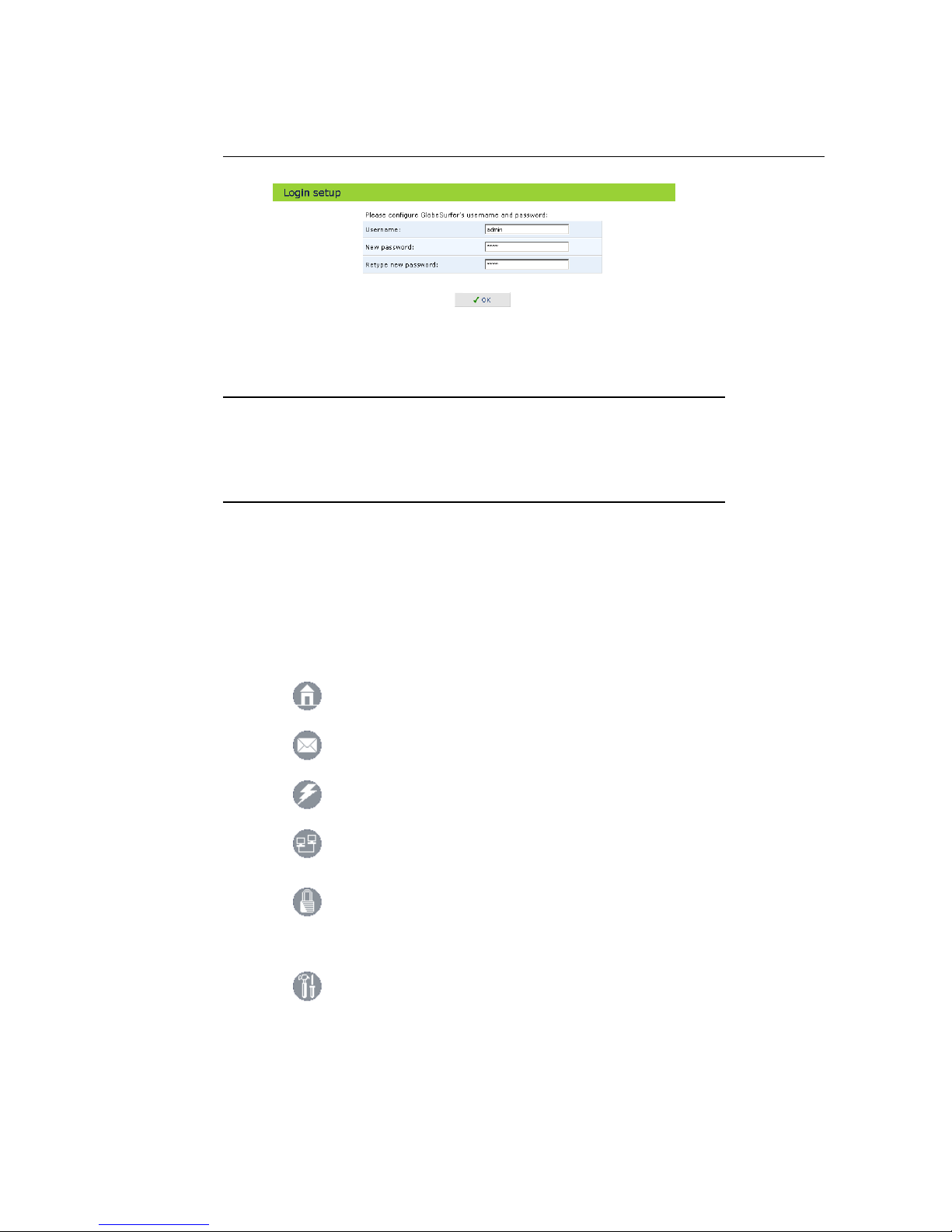
Figure 2.1: First Time Login
Your session will automatically time-out after a few minutes of inactivity. If
you try to operate the management console after the session has expired the
Login screen will appear and you will have to reenter your user name and password before proceeding. This feature helps to prevent unauthorized users from
accessing the management console and changing the GlobeSurfer 3G settings.
2.2 Left Sidebar
The GlobeSurfer 3G management console screens have been grouped into several subject areas and may be accessed by clicking on the appropriate icon in
the left sidebar.
The subject areas are:
Connection status: Display the status of the
UMTS connection (see Section 2.2)
SMS: Send, receive and maintain SMS messages
(see Chapter
3)
Quick setup: Quickly configure your
GlobeSurfer 3G (see Section 1.5)
Network connections: Create and configure network connections (see Chapter 4)
Security: Configure the Firewall and regulate
communication between the Internet and the local network (see Chapter 5)
Advanced: Control system parameters (DHCP
server, DNS) and perform administrative functions, including changing password, setting date
and time and upgrading the system (see Chapter 6)
12
Page 21
System monitoring: View network status, traffic
statistics and the system log (see Chapter 7)
Logout: Log out from GlobeSurfer 3G
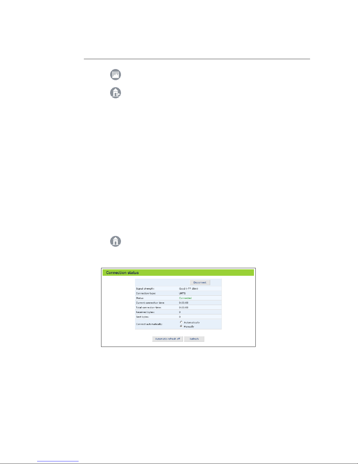
2.3 UMTS Connection Status
The Connection status screen shows the status of the UMTS connection and provides a button to manually connect and disconnect. To connect automatically
as required, for example when an Internet address is entered in the browser,
select the radio button Automatically.
The following additional information is provided:
• Current connection time: the duration of the current connection.
• Total connection time: the cumulated duration of all connections.
• Bytes received: the amount of data received in bytes.
• Bytes sent: the amount of data sent in bytes.
The information in Connection status can be refreshed and updated manually
by clicking Refresh. You can also set Connection status to update automatically
by clicking Automatic refresh on once.
View UMTS connection status.
Figure 2.2: UMTS Connection Status
13
Page 22
2.4 Getting Help
The help icon on the upper right side of the management console may be used
to get on-line help about the settings you see on each particular screen.
View help information about each specific management console screen.
2.5 Managing Tables
Tables are used throughout the GlobeSurfer 3G management console. They
handle user-defined entries relating to elements such as network connections,
local servers, restrictions and configurable parameters. The principles outlined
in this section apply to all tables in the management console.
Figure 2.3: Typical Table Structure
Figure 2.3 illustrates a typical table. Each row defines an entry in the table.
The following icons located in the Action column enable adding, editing and
deleting table entries:
Click the Add icon to add an entry of the same type as on that row.
Click the Edit icon to edit the entry on that row.
Click the Delete icon to remove the entry on that row.
In many tables the last row includes a link that allows adding a new entry to
the table.
14
Page 23
3
SMS Manager
The SMS Manager is used for sending, receiving and managing your SMS messages. Using the SMS Manager is just like using the SMS functions on a mobile
phone, but with the convenience of a full size PC screen and keyboard.
Access the SMS Manager by clicking SMS in the
left sidebar.
The display of the GlobeSurfer 3G shows an envelope symbol when a new SMS
message is received.
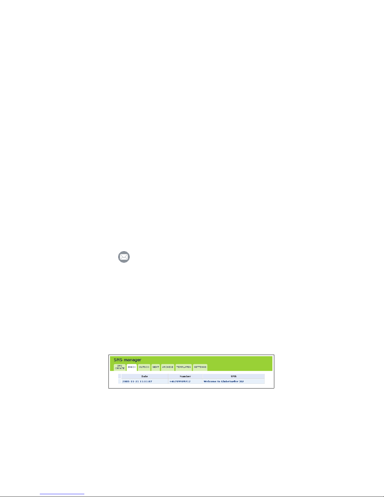
3.1 Reading an SMS
1. When starting the SMS Manager the Inbox tab of the SMS Manager is
displayed (see figure 3.1). The inbox displays all received SMS messages
in a table. Unread SMS messages are shown in bold.
Figure 3.1: SMS Manager Inbox
2. Click the SMS in the table that you want to read. The complete message
text is shown.
15
Page 24
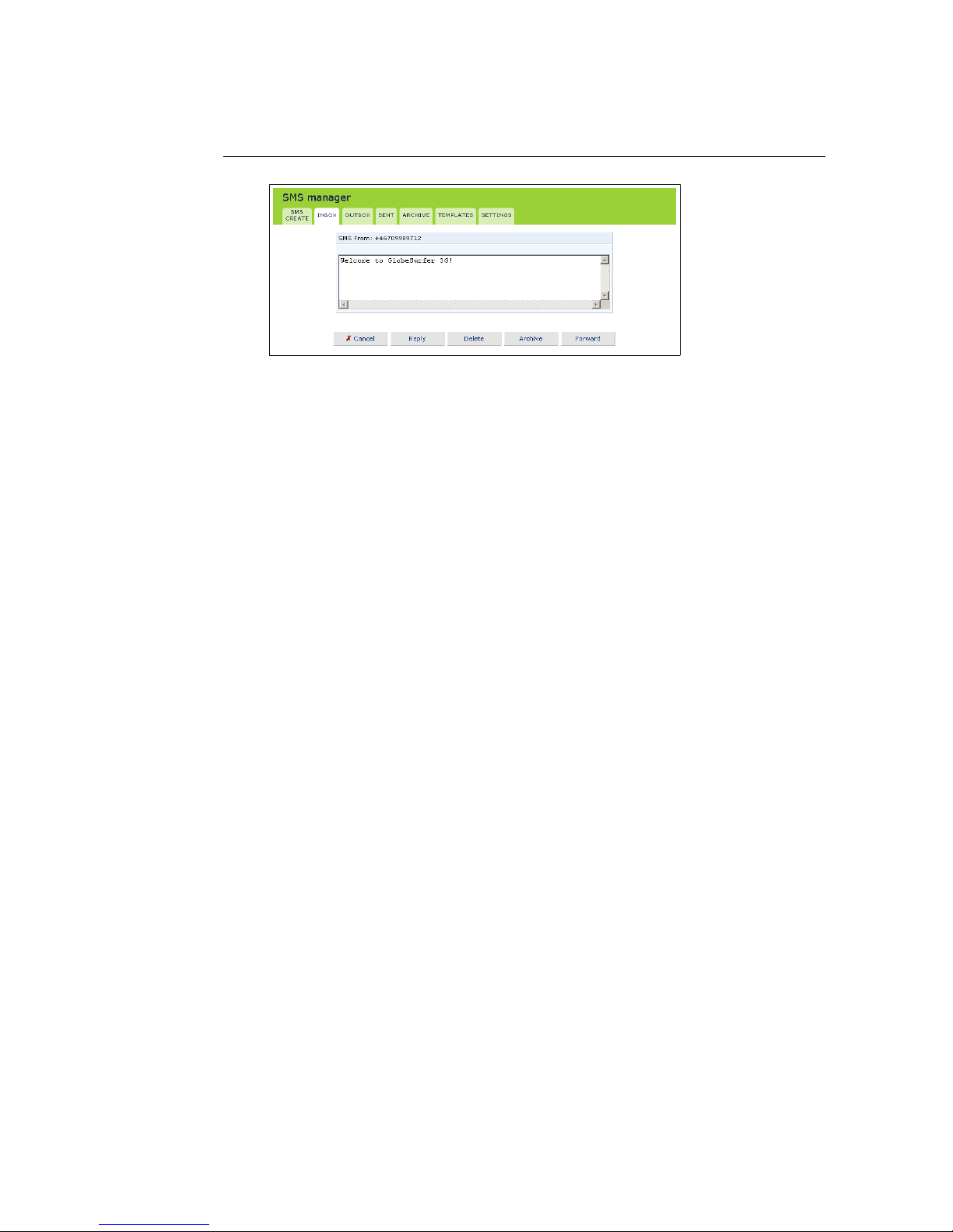
Figure 3.2: Reading an SMS
3. When you have read the SMS you can click any of the buttons underneath
to:
• Reply to the sender. You will then be moved to the SMS create
screen with the received text displayed and the phone number of
the sender already filled in (see Section 3.2).
• Delete the SMS. Note: The SMS is deleted immediately without confirmation and is not possible to restore.
• Archive the SMS (see Section 3.3).
• Forward the SMS. You will be moved to SMS Create with the received text displayed (see Section 3.3).
3.2 Creating an SMS
1. Select the SMS create tab of the SMS Manager.
2. Type your message text in the SMS message field. The Characters left field
shows how many characters you can type before the size limit is reached.
3. Enter the phone number of the receiver in the Phone numbers field. Ad-
ditional numbers can be separated with a comma. Maximum 10 numbers
are allowed. The phone number should be formated like +49176123456789
for international and like 0176123456789 for national numbers.
4. Select the Flash SMS checkbox if you want the SMS to be shown in full on
the receiver’s display immediately when received (not supported by all
mobile terminals).
5. Click the Send button when ready. Or click the Save as template button to
save the message as a template for future use.
16
Page 25
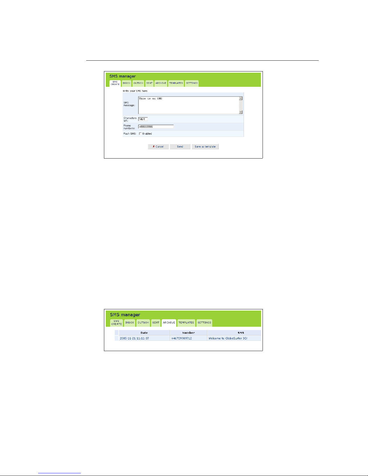
Figure 3.3: Creating an SMS
3.2.1 Sent folder
The SMS is put in the Sent folder whether it was successfully sent or not.
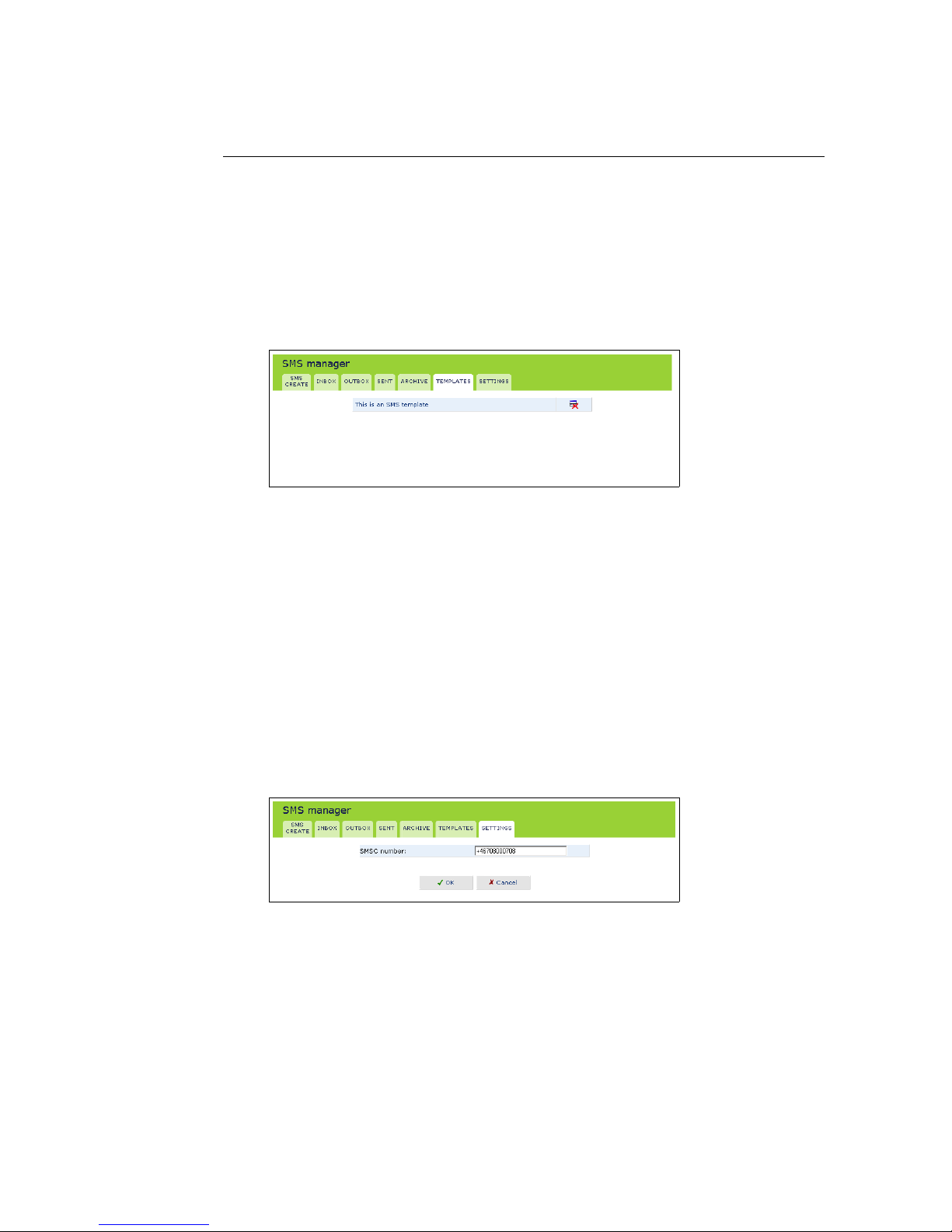
3.3 Archiving an SMS
The SMS archive is a storage area for SMS messages that you want to save. The
total maximum number of SMS messages in the Sent, Outbox, Archive and
Templates folders is 100.
1. Select the SMS that you want to store, either from the Inbox or from the
Sent folder.
2. Click the Archive button below the open SMS. The message is moved to
the archive.
3. Select the Archive tab and check that the message has been added to the
archive table.
Figure 3.4: The SMS archive
3.4 SMS Templates
Templates can be used when you write messages with similar contents. Then
create an SMS with the standard text and save it as a template.
17
Page 26
• To create a new template:
1. Select the SMS Create tab to create a new message to use as a tem-
plate (see Section 3.2).
2. Click the Save as template button when ready.
• To use an existing template:
1. Select the Templates tab, and then click the message that you want to
use.
Figure 3.5: SMS Templates
You are then moved to the SMS create tab to change the text and to
enter the phone number of the receiver, as required.
2. Click the Send button when ready.
3.5 SMS Settings
The only specific SMS Manager setting you can do is to set the number to the
Short Message Service Center (SMSC number). This number is normally preconfigured by your ISP and stored in the SIM card.
Click the Settings tab to display the SMSC number. Enter the new number and
click OK.
Figure 3.6: SMS Manager Settings
18
Page 27

4
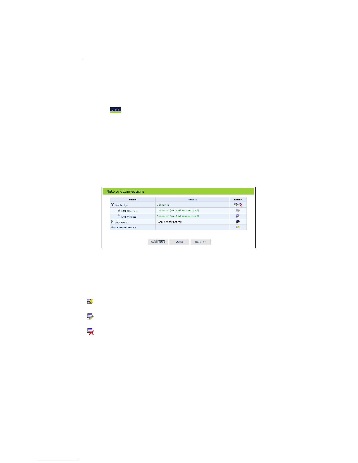
Network Connections
The Network connections screen enables you to configure the various parameters
of each LAN, WAN and VPN connection. The following sections describe the
network connection screens to configure:
• WAN - Connecting via UMTS to the Internet
– UMTS connection (see Section 4.1).
• LAN - Creating a local network
– Ethernet connection (see Section 4.2).
– Wireless connection (see Section 4.3).
– LAN bridge connection (see Section 4.4).
• VPN - Creating a secured connection
– PPTP (see Section 4.5).
– LT2P (see Section 4.6)
– IPsec (see Section 4.7).
19
Page 28
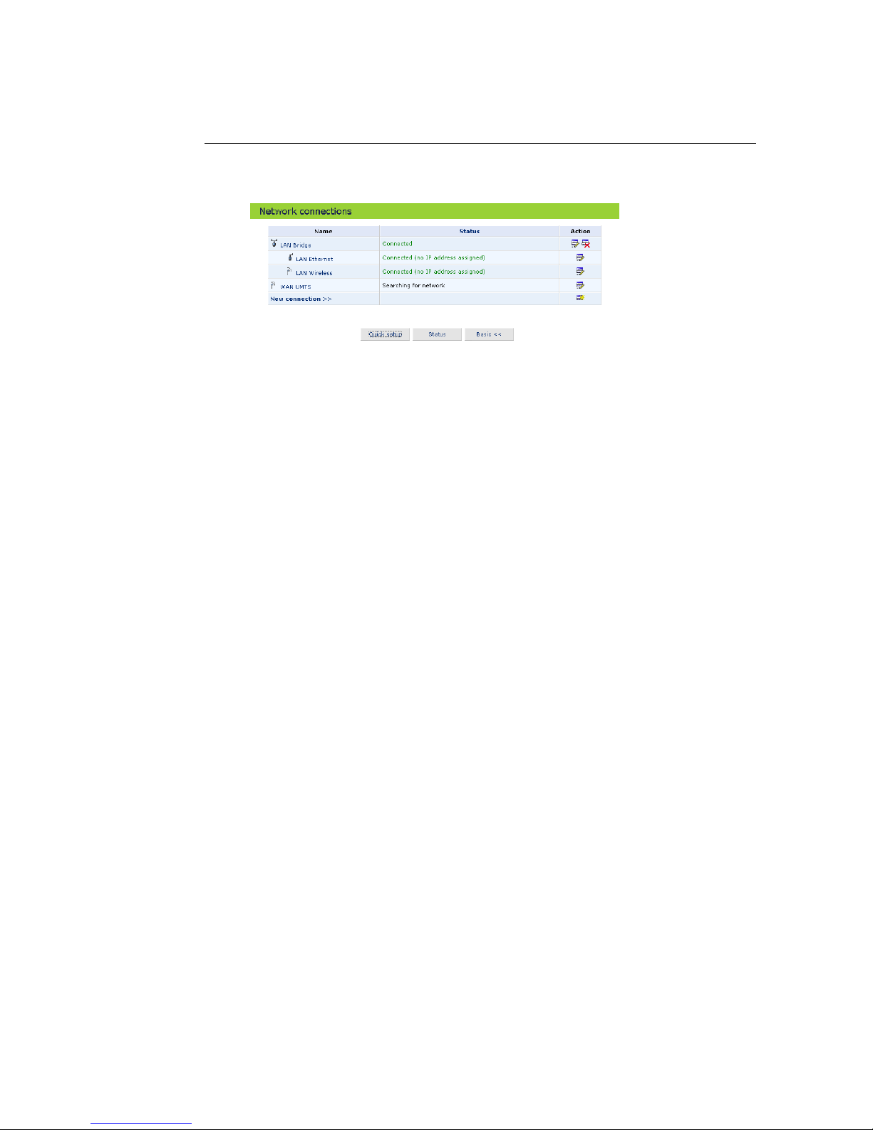
1. Click the Network connections icon on the sidebar. (see figure 4.1).
Figure 4.1: Network connections – Advanced
2. Click your connection entry in the network connections table to view the
connection properties.
3. Click New connection to start a wizard to create a new connection type.
20
Page 29
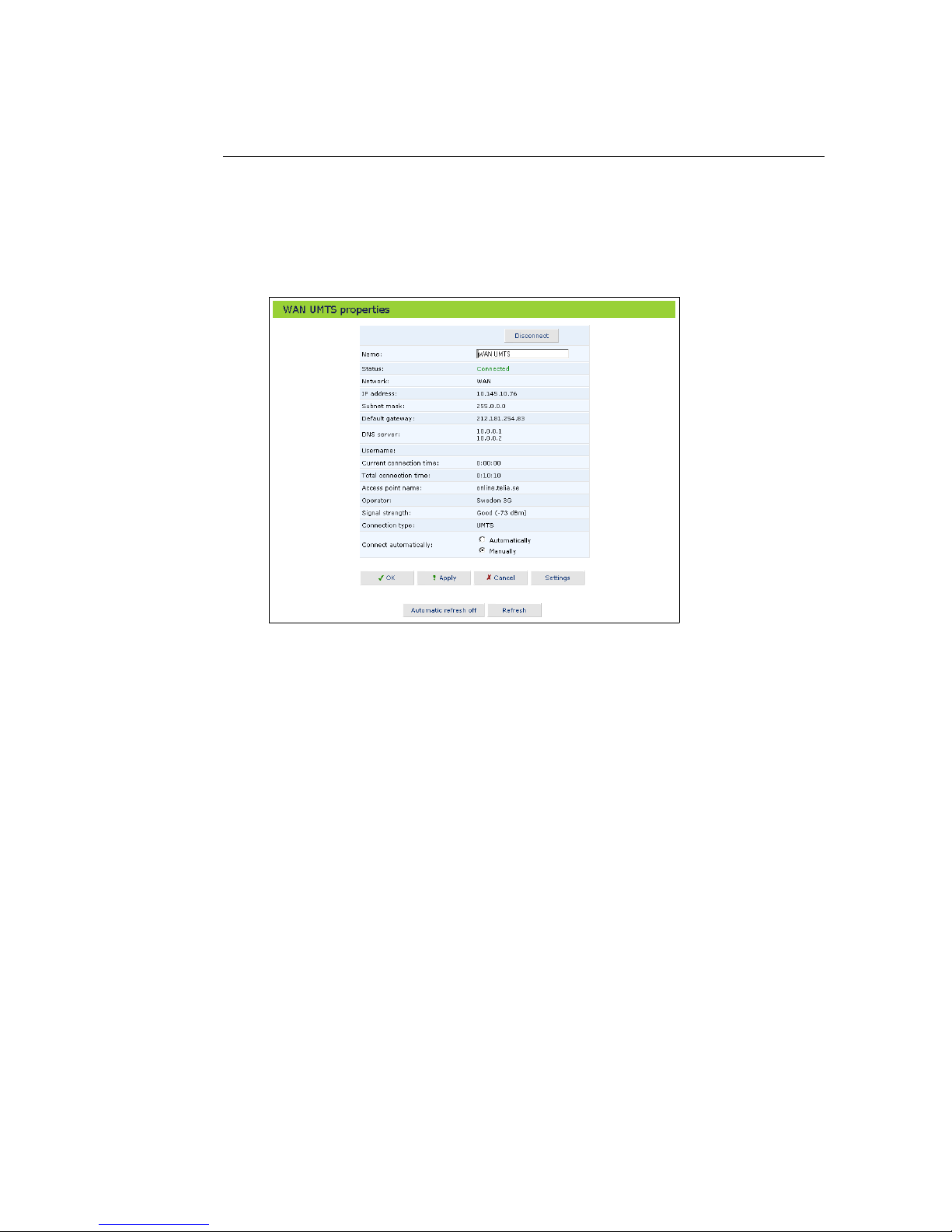
4.1 WAN UMTS Connection
The UMTS connection connects the GlobeSurfer 3G to the Internet and other
networks through the 3G/UMTS mobile telecommunications standard. The
WAN UMTS properties screen displays a summary of the connection properties.
Figure 4.2: WAN UMTS Properties
Clicking on the Settings button at the bottom-right of the connection’s Properties window, will open its Configuration window.
21
Page 30
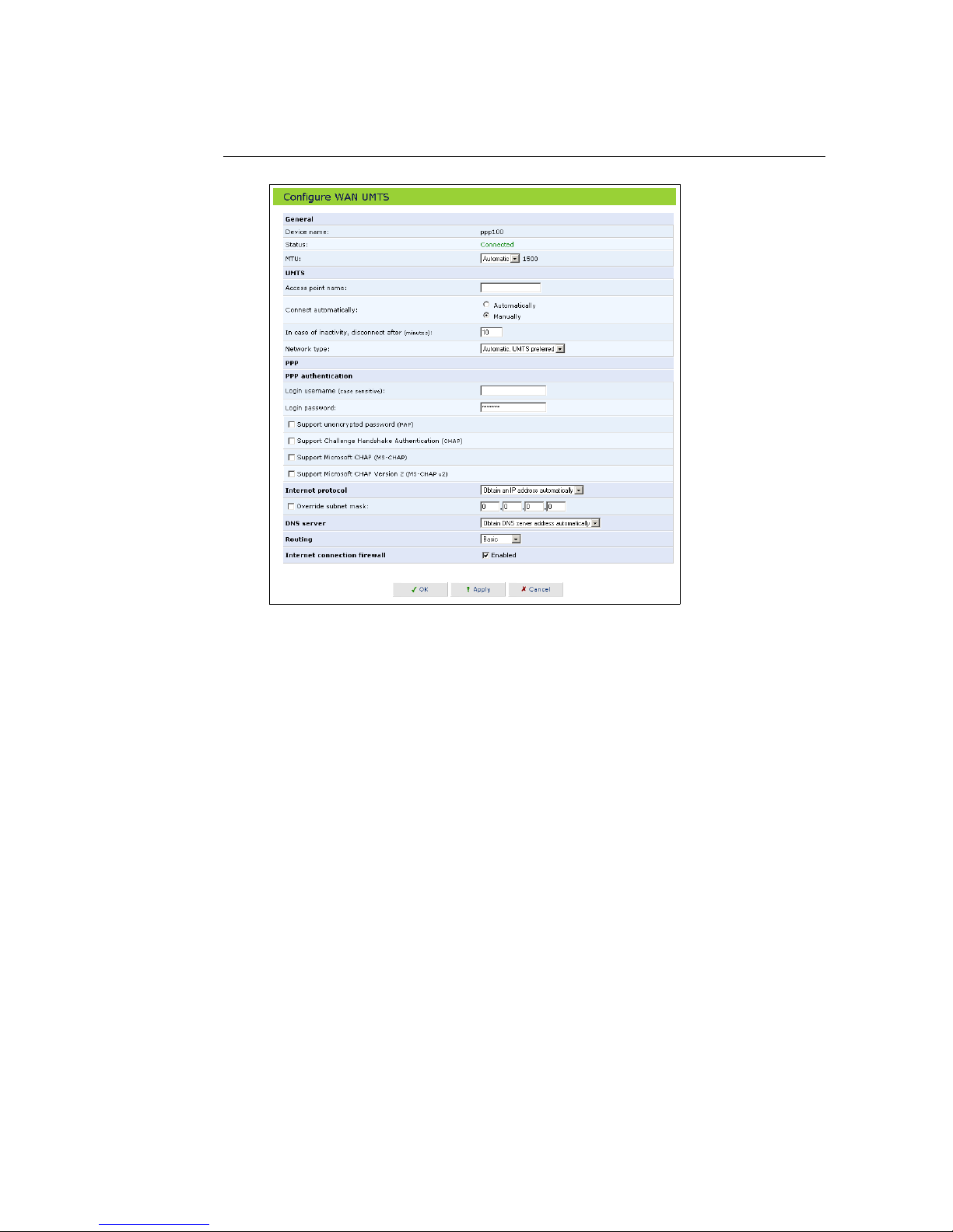
Figure 4.3: WAN UMTS Configuration
4.1.1 General Network Connection Parameters
MTU MTU is the Maximum Transmission Unit. It specifies the largest packet
size permitted for Internet transmission. The setting Manual, allows you
to enter the largest packet size that will be transmitted. To have the
GlobeSurfer 3G select the best MTU for your Internet connection, select
Automatic.
4.1.2 UMTS
• Access point name: Enter the access point name as provided by your
Internet Service Provider (ISP), or accept the name already set.
• Connect automatically: To automatically set up a UMTS connection when
data is about to be sent or received, select Automatically. If Manually is
selected, you must press the Connect button on the GlobeSurfer 3G to
connect each time a connection is required.
• Inactivity timeout: There is normally no need to change the default value
of 10 minutes. Set it to zero (0) if you don’t want the UMTS connection to
disconnect automatically at all. The inactivity timeout is not affected by
incoming traffic.
22
Page 31

• Network type: Select one of the following settings (not available in some
product versions):
– Automatic: The GlobeSurfer 3G automatically connects using the
network type that gives the best connection, UMTS or GPRS.
– Automatic, UMTS preferred: The GlobeSurfer 3G connects using
UMTS. If UMTS fails, GPRS is used instead.
– Automatic, GPRS preferred: The GlobeSurfer 3G connects using
GPRS. If GPRS fails, UMTS is used instead.
– UMTS only: The GlobeSurfer 3G connects using UMTS only.
– GPRS only: The GlobeSurfer 3G connects using GPRS only.
4.1.3 PPP Authentication
Point-to-Point Protocol (PPP) currently supports four authentication protocols:
Password Authentication Protocol (PAP), Challenge Handshake Authentication Protocol (CHAP), and Microsoft CHAP version 1 and 2.
Please note that encryption is performed only if Microsoft CHAP, Microsoft CHAP
version 2, or both are selected.
Figure 4.4: PPP Authentication Settings
Login username As agreed with ISP.
Login password As agreed with ISP.
Support unencrypted password (PAP) Password Authentication Protocol (PAP)
is a simple, plaintext authentication scheme. The user name and password are requested by your networking peer in plaintext. PAP, however, is not a secure authentication protocol. Man-in-the-middle attacks
can easily determine the remote access client’s password. PAP offers no
protection against replay attacks, remote client impersonation, or remote
server impersonation.
Support Challenge Handshake Authentication (CHAP) The Challenge Hand-
shake Authentication Protocol (CHAP) is a challenge-response authentication protocol that uses MD5 to hash the response to a challenge. CHAP
protects against replay attacks by using an arbitrary challenge string per
authentication attempt.
Support Microsoft CHAP Select this check box if you are communicating with
a peer that uses Microsoft CHAP authentication protocol.
23
Page 32

Support Microsoft CHAP Version 2 Select this check box if you are commu-
nicating with a peer that uses Microsoft CHAP Version 2 authentication
protocol.
4.1.4 Internet Protocol Settings
Select one of the following Internet protocol options from the Internet protocol
drop down menu:
• Obtain an IP address automatically
• Use the following IP address
Please note that according to the selection you make in the Internet protocol
drop down menu, the screen will refresh and display relevant configuration
settings.
Obtain an IP address automatically Your PPP connection is configured by de-
fault to obtain an IP address automatically. You should change this configuration in case your service provider requires it.
The server that assigns the GlobeSurfer 3G with an IP address, also assigns a subnet mask. You can override the dynamically assigned subnet
mask by selecting the Override subnet mask and specifying your own mask
instead.
Figure 4.5: Internet Protocol Settings – Automatic IP
Use the following IP address Your WAN connection can be configured using
a permanent (static) IP address. Your service provider should provide
you with this IP address, subnet mask and the default gateway IP address.
Figure 4.6: Internet Protocol Settings – Static IP
4.1.5 DNS Server
Domain Name System (DNS) is the method by which website or domain names
are translated into IP addresses. You can configure the connection to automatically obtain a DNS server address, or specify such an address manually,
according to the information provided by your ISP.
24
Page 33

To configure the connection to automatically obtain a DNS server address, select Obtain DNS Server Address Automatically from the DNS Server drop down
menu.
Figure 4.7: Automatic DNS Settings
To manually configure DNS server addresses, select Use the following DNS server
addresses from the DNS server drop down menu (see figure 4.100). Specify up
to two different DNS server addresses, one primary and one secondary.
Figure 4.8: DNS Settings
To learn more about this feature, refer to Section 6.2.
4.1.6 Routing
You can choose to setup your GlobeSurfer 3G to use static or dynamic routing.
Dynamic routing automatically adjusts how packets travel on the network,
whereas static routing specifies a fixed routing path to neighboring destinations.
Routing Select Advanced or Basic routing.
Routing Mode When Advanced routing is selected, select one of the f ollowing
Routing modes:
Route Use route mode if you want your GlobeSurfer 3G to function as
a router between two networks.
NAT Network Address Translation (NAT) translates an IP address to a
valid, public address on the Internet. This adds security since internal LAN addresses are not transmitted over the Internet. In addition, NAT allows many addresses to exist behind a single valid
address. Use the NAT routing mode if your LAN consists of a single device, otherwise collisions may occur if more than one device
attempts to communicate using the same port.
NAPT Network Address and Port Translation (NAPT) refers to network
address translation involving the mapping of port numbers, allowing multiple machines to share a single IP address. Use NAPT if
your LAN encompasses multiple devices, a topology that necessitates port translation in addition to address translation.
25
Page 34

Device metric The device metric is a value used by the GlobeSurfer 3G to de-
termine whether one route is superior to another, considering parameters
such as bandwidth, delay, and more.
Default route Select this check box to define this device as the default route.
Routing Information Protocol (RIP) Select this check box to enable the Rout-
ing Information Protocol (RIP). RIP determines a route based on the smallest hop count between source and destination. When RIP is enabled, select the following:
• Listen to RIP messages - select None, RIPv1, RIPv2 or RIPv1/2.
• Send RIP messages - select None, RIPv1, RIPv2-broadcast or RIPv2-
multicast.
Multicast - IGMP proxy internal IGMP proxy enables the system to issue IGMP
host messages on behalf of hosts that the system discovered through standard IGMP interfaces. IGMP proxy enables the routing of multicast packets according to the IGMP requests of LAN devices asking to join multicast groups. Select the Multicast IGMP proxy internal check-box to enable
this feature.
Routing table Allows you to add or modify routes when this device is active.
Click the link to an existing route to edit it, or click New Route to add a
route.
Figure 4.9: Advanced Routing Properties
To learn more about this feature, refer to Section 6.7.
4.1.7 Additional Network Connection Settings
Internet connection firewall Select this check box to enable the GlobeSurfer
3G firewall on the connection. To learn more about configuring security
settings, please refer to Chapter 5.
Figure 4.10: Internet Connection Firewall
26
Page 35

4.2 LAN Ethernet Connection
A LAN Ethernet connection connects local computers to GlobeSurfer 3G using
Ethernet cables, either directly or via network hubs and switches. The LAN
Ethernet Properties screen displays a summary of the connection properties.
Figure 4.11: LAN Ethernet Properties
Clicking on the Settings button at the bottom-right of the connection’s Properties window, will open its Configuration window.
Figure 4.12: LAN Ethernet Configuration
4.2.1 General Network Connection Parameters
The top part of the configuration window displays general communication parameters. It is recommended not to change the default values in this screen unless you are familiar with the networking concepts they represent. Since your
GlobeSurfer 3G is configured to operate with the default values, no parameter
modification is necessary. You can configure the following general connection
settings:
Schedule You can configure scheduler rules in order to define time segments
during which the connection is active. To configure scheduler rules click
the New link. To learn how to configure scheduler rules please refer to
Section 6.11.
27
Page 36

Physical Address The physical address of the network card used for your net-
work. Some cards allow you to change this address.
MTU MTU is the Maximum Transmission Unit. It specifies the largest packet
size permitted for Internet transmission. The setting Manual, allows you
to enter the largest packet size that will be transmitted. To have the
GlobeSurfer 3G select the best MTU for your Internet connection, select
Automatic.
4.2.2 Internet Protocol
Select one of the following Internet protocol options from the Internet protocol
drop down menu:
• No IP address
• Obtain an IP address automatically
• Use the following IP address
Please note that according to the selection you make in the Internet protocol
drop down menu, the screen will refresh and display relevant configuration
settings.
No IP address Select No IP address if you require that this connection will have
no IP address. This can be useful if this connection is under a bridge.
Figure 4.13: Internet Protocol Settings – No IP address
Obtain an IP address automatically A LAN connection can be configured to
obtain an IP address automatically. You should only change this configuration in case your service provider requires it.
The server that assigns the GlobeSurfer 3G with an IP address, also assigns a subnet mask. You can override the dynamically assigned subnet
mask by selecting the Override subnet mask and specifying your own mask
instead.
Use the following IP address The LAN connection is usually configured us-
ing a permanent (static) IP address. Your service provider should provide
you with this address and subnet mask.
Figure 4.14: Internet Protocol Settings – Static IP
28
Page 37

4.2.3 DNS Server
Domain Name System (DNS) is the method by which website or domain names
are translated into IP addresses. You can configure the connection to automatically obtain a DNS server address, or specify such an address manually,
according to the information provided by your ISP.
To configure the connection to automatically obtain a DNS server address, select Obtain DNS Server Address Automatically from the DNS Server drop down
menu.
Figure 4.15: Automatic DNS Settings
To manually configure DNS server addresses, select Use the following DNS server
addresses from the DNS server drop down menu (see figure 4.100). Specify up
to two different DNS server addresses, one primary and one secondary.
Figure 4.16: DNS Settings
To learn more about this feature, refer to Section 6.2.
4.2.4 DHCP
The DHCP section allows you to configure the Dynamic Host Configuration
Protocol (DHCP) server parameters of the GlobeSurfer 3G. The DHCP automatically assigns IP addresses to network PCs. If you enable this feature, make
sure that you also configure every network PC as DHCP Client.
Figure 4.17: IP Address Distribution
Select one of the following options from the DHCP drop down menu:
29
Page 38

• DHCP server
Start IP address Specify the IP address from which the gateway starts
issuing addresses. Since the gateway’s default IP address is 192.168.1.1,
the Start IP address must be 192.168.1.2 or greater.
End IP address Specify the end of the IP address range that can be used
to automatically issue IP addresses.
Subnet mask The subnet mask determines which portion of a destina-
tion LAN IP address is the network portion, and which portion is
the host portion.
WINS server IP address If you use a Windows Internet Naming Service
(WINS), specify the WINS server address in this field.
Lease time in minutes This is duration of time a network user will be al-
lowed connection to the gateway with its currently issued dynamic
IP address. Just before the time is up, the user will automatically
request to extend the lease or get a new IP address.
Provide host name if not specified by client Mark this check box if you
want the gateway to automatically assign network PCs with a host
name, in case a host name is not provided by the user.
Figure 4.18: IP Address Distribution - DHCP Server
• DHCP relay
Your gateway can act as a DHCP relay, if you require receiving a dynamically assigned IP address from a DHCP server other than your gateway’s
DHCP server.
1. After selecting DHCP relay from the drop down menu, a New IP
address link will appear.
Figure 4.19: IP Address Distribution - DHCP Relay
Click the New IP address link. The DHCP Relay server address screen
will appear:
30
Page 39

Figure 4.20: IP Address Distribution - DHCP Server Definition
2. Specify the IP address of the DHCP server.
3. Click OK to save the setting.
• Disabled
Select Disabled from the drop down menu if you want to statically assign
IP addresses to your network computers.
Figure 4.21: IP Address Distribution - Disable DHCP
Click OK to save the setting.
4.2.5 Routing
You can choose to setup your GlobeSurfer 3G to use static or dynamic routing.
Dynamic routing automatically adjusts how packets travel on the network,
whereas static routing specifies a fixed routing path to neighboring destinations.
Routing Select Advanced or Basic routing.
Device Metric The device metric is a value used by the GlobeSurfer 3G to de-
termine whether one route is superior to another, considering parameters
such as bandwidth, delay, and more.
Default Route Select this check box to define this device as a the default route.
Routing Information Protocol (RIP) Select this check box to enable the Rout-
ing Information Protocol (RIP). RIP determines a route based on the smallest hop count between source and destination. When RIP is enabled, select the following:
• Listen to RIP messages - select None, RIPv1, RIPv2 or RIPv1/2.
• Send RIP messages - select None, RIPv1, RIPv2-broadcast or RIPv2-
multicast.
31
Page 40

Figure 4.22: Advanced Routing Properties
To learn more about this feature, refer to Section 6.7.
4.2.6 Additional Network Connection Settings
The bottom part of the configuration screen displays the following options:
Internet connection firewall Select this check box to enable the GlobeSurfer
3G firewall on the connection. To learn more about configuring security
settings, please refer to Chapter 5.
Figure 4.23: Additional Network Connection Parameters
32
Page 41

4.3 LAN Wireless Connection
This section begins with basic instructions to quickly and easily configure your
wireless network, and continues with advanced settings options.
4.3.1 Configuring Your Wireless Network
As soon as GlobeSurfer 3G is active, your wireless network is available. This
section will familiarize you with GlobeSurfer 3G’s wireless configuration, and
demonstrate how to connect a wireless PC to the network.
4.3.1.1 Configuring your GlobeSurfer 3G Wireless Connection
GlobeSurfer 3G will automatically set up a wireless connection as a bridged
LAN network device.
1. Click the Network Connections icon on the sidebar, the Network Connections
screen will appear (see figure 4.33).
Figure 4.24: Network Connections
2. Click the LAN wireless connection link (or its Edit icon) to view its properties. The LAN Wireless Properties screen will appear (see figure 4.34).
Figure 4.25: LAN Wireless Properties
3. Click the Settings button to display the various wireless connection settings. The Configure LAN Wireless screen will appear (see figure 4.35).
33
Page 42

Figure 4.26: Configure LAN Wireless
4. In the SSID field, change the broadcasted name of your wireless network
from the default to a more unique name. Click OK, then click OK again
on the properties screen to save your changes.
A comprehensive description of all the wireless connection settings in the configuration screen is available in section 4.3.3.
4.3.1.2 Configuring Your Wireless Windows XP Client
If your PC has wireless capabilities, Windows XP will automatically recognize
this and create a wireless connection for you. You can view this connection
under Window’s Network Connections.
Note: The following descriptions and images are in accordance with Microsoft
Windows XP, Version 2002, running Service Pack 2.
1. Open your Network Connections window from Windows Control Panel
(see figure 4.38).
34
Page 43

Figure 4.27: Network Connections
2. Double-click the wireless connection icon. The Wireless Network Connec-
tion screen will appear, displaying all available wireless networks in your
vicinity. If your gateway is connected and active, you will see GlobeSurfer
3G’s wireless connection (see figure 4.28). Note that the connection’s status is Not connected and defined as ”Unsecured wireless network”.
35
Page 44

Figure 4.28: Available Wireless Connections
3. Select the wireless network name (SSID) that you configured in the Con-
figure LAN Wireless screen (see figure 4.35) as your wireless network. Se-
lect the Enable IEEE 802.1x authentication for this network check box to enable authenticated communication between the PC and the GlobeSurfer
3G. If you choose to enable 802.1x, you must also configure the GlobeSurfer
3G accordingly.
4. Click the Advanced button, the Wireless network properties screen will appear (see figure 4.29).
36
Page 45

Figure 4.29: Wireless Connection Association
5. Select the Data Encryption (WEP) check box to encrypt the Wireless data
transmitted between GlobeSurfer 3G and your Wireless device.
6. Select the Authentication tab to configure wireless authentication protocols (see figure 4.30). When selecting an EAP Type authentication method,
make sure that your GlobeSurfer 3G is configured accordingly.
37
Page 46

Figure 4.30: Wireless Connection Authentication
7. Click the connection once to mark it and then click the Connect button at
the bottom of the screen. After the connection is established, its status
will change to Connected:
Figure 4.31: Connected Wireless Network
An icon will appear in the notification area, announcing the successful
initiation of the wireless connection (see figure 4.42).
38
Page 47

Figure 4.32: Wireless Connection Information
8. Test the connection by disabling all other connections in the Network
Connections window (see figure 4.38) and browsing the Internet.
You can now use GlobeSurfer 3G’s wireless network from the configured PC.
However, so can any other user with a wireless PC, which happens to be in
your network’s radio range. To prevent this scenario, the next step is to secure
your wireless network, allowing only specific users to connect.
4.3.2 Securing Your Wireless Network
The GlobeSurfer 3G wireless network is ready for operation with its default
values. However, as soon as your wireless connection is established, any computer with a wireless capability can connect to your LAN. The following section describes how to secure your wireless connection using the Wi-Fi Pro-
tected Access (WPA) security protocol.
The Wi-Fi Alliance created the WPA security protocol as a data encryption
method for 802.11 wireless local area networks (WLANs). WPA is an industrysupported, pre-standard version of 802.11i utilizing the Temporal Key Integrity
Protocol (TKIP), which fixes the problems of Wired Equivalent Privacy (WEP),
including the use of dynamic keys.
4.3.2.1 Securing Your Wireless Network with WPA
1. Click the Network Connections icon on the sidebar, the Network Connections
screen will appear (see figure 4.33).
Figure 4.33: Network Connections
2. Click the LAN wireless connection link (or its Edit icon) to view its properties. The LAN Wireless Properties screen will appear (see figure 4.34).
39
Page 48

Figure 4.34: LAN Wireless Properties
3. Click the Settings button to display the various wireless connection settings. The Configure LAN Wireless screen will appear (see figure 4.35).
Figure 4.35: Configure LAN Wireless
4. Enable the Wireless security feature by checking its Enabled check box.
40
Page 49

The screen will refresh, displaying the wireless security options (see figure 4.50).
5. Verify that the Stations security type is set to Accept WPA stations.
6. Verify that the Authentication method selected is Pre-Shared key.
7. Enter a phrase of at least 8 characters in the Pre-Shared key text field. Verify
that ASCII is selected in the associated combo box
Figure 4.36: LAN Wireless Security Parameters
8. Click OK. An Attention screen will appear warning you that the browser
page might require reloading.
Figure 4.37: Browser Reload Warning
9. Click OK to save the changes.
Make the corresponding settings on your Windows PC Client as described below.
4.3.2.2 Connecting a Wireless Windows XP Client to the Secured Wireless
Network
1. Open your Network Connections window from Window’s Control Panel
(see figure 4.38).
41
Page 50

Figure 4.38: Network Connections
2. Double-click the wireless connection icon. The Wireless Network Connec-
tion screen will appear, displaying GlobeSurfer 3G’s wireless connection
(see figure 4.39). Note that the connection is defined as ”Security-enabled
wireless network (WPA)”.
42
Page 51

Figure 4.39: Available Wireless Connections
3. Click the connection once to mark it and then click the Connect button at
the bottom of the screen. The following login window will appear, asking for a Network Key, which is the pre-shared key you have configured
above.
Figure 4.40: Wireless Network Connection Login
4. Enter the pre-shared key in both fields and click the Connect button. After
the connection is established, its status will change to Connected:
Figure 4.41: Connected Wireless Network
43
Page 52

An icon will appear in the notification area, announcing the successful
initiation of the wireless connection (see figure 4.42).
Figure 4.42: Wireless Connection Information
5. Test the connection by disabling all other connections in the Network
Connections window (see figure 4.38) and browsing the Internet.
Should the login window above not appear and the connection attempt fail,
please configure Window’s connection manually:
1. Click the connection once to mark it and then click the Change advanced
settings link in the Related Tasks box on the left part of the window (see
figure 4.43).
Figure 4.43: Related Tasks
2. The Wireless Network Connection Properties window will appear. Select the
Wireless Networks tab (see figure 4.44).
44
Page 53

Figure 4.44: Wireless Network Connection Properties
3. Click your connection to highlight it and then click the Properties button.
Your connection’s properties window will appear (see figure 4.45).
45
Page 54

Figure 4.45
Connection Properties Configuration
• In the Network Authentication combo box, select ”WPA-PSK”.
• In the Data Encryption combo box, select ”TKIP”.
• Enter your pre-shared key in both the Network key and the Confirm
network key fields.
4. Click OK on both windows to save the settings.
5. When attempting to connect to the wireless network, the login window
will now appear, pre-filled with the pre-shared key. Click the Connect
button to connect.
Since your network is now secured, only users that know the pre-shared key
will be able to connect. The WPA security protocol is similiar to securing network access using a password.
46
Page 55

4.3.3 Advanced Wireless Connection Settings
The following sections describe how to configure the advanced settings of your
wireless connection, which is only recommended for advanced users. These
settings are accessible from the Configure LAN Wireless screen (see figure 4.35).
4.3.3.1 General Network Connection Parameters
The top part of the configuration window displays general communication parameters. It is recommended not to change the default values in this screen unless you are familiar with the networking concepts they represent. Since your
GlobeSurfer 3G is configured to operate with the default values, no parameter
modification is necessary. You can configure the following general connection
settings:
Schedule You can configure scheduler rules in order to define time segments
during which the connection is active. To configure scheduler rules click
the New link. To learn how to configure scheduler rules please refer to
Section 6.11.
Physical Address The physical address of the network card used for your net-
work. Some cards allow you to change this address.
MTU MTU is the Maximum Transmission Unit. It specifies the largest packet
size permitted for Internet transmission. The setting Manual, allows you
to enter the largest packet size that will be transmitted. To have the
GlobeSurfer 3G select the best MTU for your Internet connection, select
Automatic.
Figure 4.46: LAN Wireless General Connection Parameters
4.3.3.2 Wireless Access Point
SSID The SSID is the network name shared among all points in a wireless
network. The SSID must be identical for all points in the wireless network. It is case-sensitive and must not exceed 32 characters (use any of
the characters on the keyboard). Make sure this setting is the same for all
points in your wireless network. For added security, you should change
the default SSID (my-wlan) to a unique name.
SSID broadcast Select this checkbox to enable broadcasting of the SSID. Dis-
abling SSID broadcast is used in order to hide the name of the wireless
device from clients that should not be aware of its existence.
47
Page 56

802.11 Mode Select the wireless communication standard that is compatible
with your PC’s wireless card. You can work in either 802.11g, 802.11b or
in mixed mode.
Channel Select the appropriate channel from the list provided to correspond
with your network settings. All devices in your wireless network must
use the same channel in order to function correctly.
Network authentication Select Open System Authentication or Shared Key Au-
thentication.
Figure 4.47: LAN Wireless Access Point Parameters
4.3.3.3 MAC filtering settings
MAC filtering mode A common method of restricting WLAN network access
is to specify the Media Access Control (MAC) address of computers that
are allowed or denied access to your network. Every WLAN network
adapter is identified by a unique MAC address. The GlobeSurfer 3G supports MAC filtering based on either a list of denied or allowed computers. MAC filtering mode Allow specifies that the list of MAC addresses
is granted access to GlobeSurfer 3G. MAC filtering mode Deny specifies
that all computers except those in the list of MAC addresses are granted
access to GlobeSurfer 3G. Select Disable if you want to disable MAC filtering.
MAC filtering settings Click the New MAC address link to define MAC ad-
dresses to filter. The selected MAC filtering mode will be performed on
the corresponding network adapters.
Figure 4.48: LAN Wireless MAC Filtering Settings
4.3.3.4 Advanced Wireless Options
Transmission rate The transmission rate is set according to the speed of your
wireless connection. Select the transmission rate from the drop down
list, or select Auto to have GlobeSurfer 3G automatically use the fastest
possible data transmission rate.
CTS protection mode CTS protection mode boosts your gateway’s ability to
intercept Wireless-G and 802.11b transmissions. Conversely, CTS protection mode decreases performance. Leave this feature disabled unless you
48
Page 57

encounter severe communication difficulties between the GlobeSurfer 3G
and Wireless-G products.
Beacon interval A beacon is a packet broadcast by GlobeSurfer 3G to syn-
chronize the wireless network. The beacon interval value indicates how
often the beacon is sent.
DTIM interval The Delivery Traffic Indication Message (DTIM) is a count-
down value that informs wireless clients of the next opportunity to receive multicast and broadcast messages. This value ranges between 1
and 16384.
Fragmentation threshold Packets that are larger than this threshold are frag-
mented into multiple packets. Try to increase the fragmentation threshold if you encounter high packet error rates. Do not set the threshold too
low, since this can result in reduced networking performance.
RTS threshold GlobeSurfer 3G sends Request to Send (RTS) packets to the
wireless client in order to negotiate the dispatching of data. The wireless client responds with a Clear to Send (CTS) packet, signaling that
transmission can commence. In case packets are smaller than the preset threshold, the RTC/CTS mechanism is not active. If you encounter
inconsistent data flow, try a minor reduction of the RTS threshold size.
Figure 4.49: LAN Wireless Access Point Advanced Parameters
4.3.3.5 Wireless Security
To configure your wireless security, select the Enabled check-box on the Configure LAN Wireless screen (see figure 4.35). The screen will refresh, displaying the
wireless security options (see figure 4.50). Click Apply to save this change.
Stations security type Select Accept WPA stations to allow wireless clients that
use WPA to communicate with the gateway. Select Accept 802.1X WEP
stations to allow wireless clients that use standard WEP to communicate
with the gateway. Select Accept Non-802.1X WEP stations to allow wireless
clients that use non-standard WEP to communicate with the gateway.
Authentication method Select the authentication method you would like to
use from the Authentication method combo box. Choose between Pre-
Shared key and 802.1x.
Pre-Shared key This entry appears only if you had selected this authentica-
tion method. Enter your encryption key in the Pre-Shared key field. You
can use either an ASCII or a Hex value by selecting the value type in the
combo box provided.
49
Page 58

Encryption algorithm Select whether to use TKIP or AES for encryption.
Group key update interval Define the time interval in seconds for updating
a group key.
Figure 4.50: LAN Wireless Security Parameters
4.3.3.6 Internet Protocol
Select one of the following Internet protocol options from the Internet protocol
drop down menu:
• No IP address
• Obtain an IP address automatically
• Use the following IP address
Please note that according to the selection you make in the Internet protocol
drop down menu, the screen will refresh and display relevant configuration
settings.
No IP address Select No IP address if you require that this connection will have
no IP address. This can be useful if this connection is under a bridge.
Figure 4.51: Internet Protocol Settings – No IP address
Obtain an IP address automatically A LAN connection can be configured to
obtain an IP address automatically. You should only change this configuration in case your service provider requires it.
The server that assigns the GlobeSurfer 3G with an IP address, also assigns a subnet mask. You can override the dynamically assigned subnet
mask by selecting the Override subnet mask and specifying your own mask
instead.
Use the following IP address The LAN connection is usually configured us-
ing a permanent (static) IP address. Your service provider should provide
you with this address and subnet mask.
50
Page 59

Figure 4.52: Internet Protocol Settings – Static IP
4.3.3.7 Additional Network Connection Settings
The bottom part of the configuration screen displays the following options:
Internet connection firewall Select this check box to enable the GlobeSurfer
3G firewall on the connection. To learn more about configuring security
settings, please refer to Chapter 5.
Figure 4.53: Additional Network Connection Parameters
51
Page 60

4.4 LAN Bridge Connection
The LAN bridge connection is used to combine several LAN devices under
one virtual network. For example, creating one network for LAN Ethernet and
LAN wireless devices.
Please note, that when a bridge is removed, its formerly underlying devices
inherit the bridge’s DHCP settings. For example, the removal of a bridge that
is configured as DHCP client, automatically configures the LAN devices formerly constituting the bridge as DHCP clients, with the exact DHCP client
configuration.
Figure 4.54: General Bridge Settings
4.4.1 General Network Connection Parameters
The top part of the configuration window displays general communication parameters. It is recommended not to change the default values in this screen unless you are familiar with the networking concepts they represent. Since your
GlobeSurfer 3G is configured to operate with the default values, no parameter
modification is necessary. You can configure the following general connection
settings:
Physical Address The physical address of the network card used for your net-
work. Some cards allow you to change this address.
MTU MTU is the Maximum Transmission Unit. It specifies the largest packet
size permitted for Internet transmission. The setting Manual, allows you
to enter the largest packet size that will be transmitted. To have the
GlobeSurfer 3G select the best MTU for your Internet connection, select
Automatic.
52
Page 61

Figure 4.55: General Bridge Settings
4.4.2 Internet Protocol
Select one of the following Internet protocol options from the Internet protocol
drop down menu:
• No IP address
• Obtain an IP address automatically
• Use the following IP address
Please note that according to the selection you make in the Internet protocol
drop down menu, the screen will refresh and display relevant configuration
settings.
No IP address Select No IP address if you require that this connection will have
no IP address. This can be useful if this connection is under a bridge.
Figure 4.56: Internet Protocol Settings – No IP address
Obtain an IP address automatically A LAN connection can be configured to
obtain an IP address automatically. You should only change this configuration in case your service provider requires it.
The server that assigns the GlobeSurfer 3G with an IP address, also assigns a subnet mask. You can override the dynamically assigned subnet
mask by selecting the Override subnet mask and specifying your own mask
instead.
Use the following IP address The LAN connection is usually configured us-
ing a permanent (static) IP address. Your service provider should provide
you with this address and subnet mask.
Figure 4.57: Internet Protocol Settings – Static IP
53
Page 62

4.4.3 Bridge Settings
The bridge section allows you to specify the LAN devices that you would like
to join under the network bridge. Click the Edit icon on the VLAN column to
assign the network connections to specific Virtual LANs.
Select the STP check box to enable the Spanning Tree Protocol on the device.
You should use this to ensure that there are no loops in your network configuration, and apply these settings in case your network consists of multiple
switches, or other bridges apart from those created by the GlobeSurfer 3G.
Figure 4.58: LAN Bridge Settings
4.4.4 DNS Server
Domain Name System (DNS) is the method by which website or domain names
are translated into IP addresses. You can configure the connection to automatically obtain a DNS server address, or specify such an address manually,
according to the information provided by your ISP.
To configure the connection to automatically obtain a DNS server address, select Obtain DNS Server Address Automatically from the DNS Server drop down
menu.
Figure 4.59: Automatic DNS Settings
To manually configure DNS server addresses, select Use the following DNS server
addresses from the DNS server drop down menu (see figure 4.100). Specify up
to two different DNS server addresses, one primary and one secondary.
Figure 4.60: DNS Settings
To learn more about this feature, refer to Section 6.2.
54
Page 63

4.4.5 DHCP
The DHCP section allows you to configure the Dynamic Host Configuration
Protocol (DHCP) server parameters of the GlobeSurfer 3G. The DHCP automatically assigns IP addresses to network PCs. If you enable this feature, make
sure that you also configure every network PC as DHCP Client.
Figure 4.61: IP Address Distribution
Select one of the following options from the DHCP drop down menu:
• DHCP server
Start IP address Specify the IP address from which the gateway starts
issuing addresses. Since the gateway’s default IP address is 192.168.1.1,
the Start IP address must be 192.168.1.2 or greater.
End IP address Specify the end of the IP address range that can be used
to automatically issue IP addresses.
Subnet mask The subnet mask determines which portion of a destina-
tion LAN IP address is the network portion, and which portion is
the host portion.
WINS server IP address If you use a Windows Internet Naming Service
(WINS), specify the WINS server address in this field.
Lease time in minutes This is duration of time a network user will be al-
lowed connection to the gateway with its currently issued dynamic
IP address. Just before the time is up, the user will automatically
request to extend the lease or get a new IP address.
Provide host name if not specified by client Mark this check box if you
want the gateway to automatically assign network PCs with a host
name, in case a host name is not provided by the user.
55
Page 64

Figure 4.62: IP Address Distribution - DHCP Server
• DHCP relay
Your gateway can act as a DHCP relay, if you require receiving a dynamically assigned IP address from a DHCP server other than your gateway’s
DHCP server.
1. After selecting DHCP relay from the drop down menu, a New IP
address link will appear.
Figure 4.63: IP Address Distribution - DHCP Relay
Click the New IP address link. The DHCP Relay server address screen
will appear:
Figure 4.64: IP Address Distribution - DHCP Server Definition
2. Specify the IP address of the DHCP server.
3. Click OK to save the setting.
• Disabled
Select Disabled from the drop down menu if you want to statically assign
IP addresses to your network computers.
Figure 4.65: IP Address Distribution - Disable DHCP
Click OK to save the setting.
56
Page 65

4.4.6 Routing
You can choose to setup your GlobeSurfer 3G to use static or dynamic routing.
Dynamic routing automatically adjusts how packets travel on the network,
whereas static routing specifies a fixed routing path to neighboring destinations.
Routing Select Advanced or Basic routing.
Device metric The device metric is a value used by the GlobeSurfer 3G to de-
termine whether one route is superior to another, considering parameters
such as bandwidth, delay, and more.
Default route Select this check box to define this device as the default route.
Multicast - IGMP proxy internal IGMP proxy enables the system to issue IGMP
host messages on behalf of hosts that the system discovered through standard IGMP interfaces. IGMP proxy enables the routing of multicast packets according to the IGMP requests of LAN devices asking to join multicast groups. Select the Multicast IGMP proxy internal check-box to enable
this feature.
Routing Information Protocol (RIP) Select this check box to enable the Rout-
ing Information Protocol (RIP). RIP determines a route based on the smallest hop count between source and destination. When RIP is enabled, select the following:
• Listen to RIP messages - select None, RIPv1, RIPv2 or RIPv1/2.
• Send RIP messages - select None, RIPv1, RIPv2-broadcast or RIPv2-
multicast.
Routing table Allows you to add or modify routes when this device is active.
Click the link to an existing route to edit it, or click New route to add a
route.
Figure 4.66: Advanced Routing Properties
To learn more about this feature, refer to Section 6.7.
4.4.7 Additional Network Connection Settings
The bottom part of the configuration screen displays the following options:
57
Page 66

Internet connection firewall Select this check box to enable the GlobeSurfer
3G firewall on the connection. To learn more about configuring security
settings, please refer to Chapter 5.
Figure 4.67: Additional Network Connection Parameters
58
Page 67

4.5 VPN PPTP
Point-to-Point Tunneling Protocol (PPTP) is a protocol developed by Microsoft
targeted at creating VPN connections over the Internet. This enables remote
users to access the gateway via any ISP that supports PPTP on its servers. PPTP
encapsulates network traffic, encrypts content using Microsoft’s Point-to-Point
Encryption (MPPE) protocol that is based on RC4, and routes using the generic
routing encapsulation (GRE) protocol.
For more information on PPTP connections, refer to Section 6.13.2 for PPTP
server settings and Section 6.13.3 for PPTP client settings.
4.5.1 Creating a PPTP Client Connection
To create a PPTP client connection, perform the following steps:
1. Click Network connections on the sidebar – the Network connections screen
will appear (see figure 4.68).
Figure 4.68: Network Connections
2. Click the New connection link to list the connection alternatives.
59
Page 68

Figure 4.69: New Connection Alternatives
3. Select the Point-to-Point Tunneling Protocol (PPTP) radio button and click Next.
The Point-to-Point Tunneling Protocol (PPTP) configuration screen will appear
(see figure 4.70).
Enter the following parameters, supplied by your VPN server.
Hostname or IP address of destination Hostname or IP address of the VPN
host server.
Login username Your username.
Login password Your passsword.
Figure 4.70: PPTP Connection Properties
Click Next when ready. The wizard will display a connection summary (see
figure 4.77).
60
Page 69

Click Finish to create your VPN PPTP client connection.
Figure 4.71: PPTP Client Connection Summary
4.5.2 Creating a PPTP Server Connection
To create a PPTP server connection, perform the following steps:
1. Click Network connections on the sidebar – the Network connections screen
will appear (see figure 4.72).
Figure 4.72: Network Connections
Click the New connection link to list the connection alternatives.
2.
Figure 4.73: New Connection Alternatives
61
Page 70

3. Select the Point-to-Point Tunneling Protocol Server (PPTP Server) radio button
and click Next.
Specify the users that will be authorized to access your VPN server (see figure 6.39).
Figure 4.74: User table
You can add, edit and delete users allowed to access the GlobeSurfer 3G and
your local network by managing the user table as described in Section 2.5. To
add a new user click New user in the table and specify the following parameters:
• Full name: The remote user’s full name.
• Username: The name the remote user will use to access your local network.
• New password: Type a new password for the remote user. If you do not
want to assign a password to the remote user leave this field empty.
• Retype new password: If a new password was assigned, type it again to
verify correctness.
• Permissions: Select the remote user’s privileges on your local network.
– Administrator privileges: Grants remote system setting modification
via the web-based management console or telnet.
– Remote access by PPTP: Grants access with no system modification
privileges.
– SMS access only: Grants access to the SMS manager only, for exam-
ple to send and read SMS messages. Other parts of the management
console will be hidden and can not be accessed.
62
Page 71

Figure 4.75: Managing Users
Please note, that changing any of the user parameters will prompt the connection associated with the user to terminate. For changes to take effect you
should activate the connection manually after modifying user parameters.
You can use email notification to receive indications of system events for a
predefined severity classification. The available types of events are System or
Security events. The available severity of events are Error, Warning and Information. If the Information level is selected the user will receive notification of
Information, Warning and Error events. If the Warning level is selected the user
will receive notification of Warning and Error events etc.
To configure email notification for a specific user:
• First make sure you have configured an outgoing mail server in System
settings. A click on the Configure mail server link will display the System
settings screen where you can configure the outgoing mail server.
• Enter the user’s email address in the Address field in the Email section.
• Select the System and Security notification levels in the System notify level
and Security notify level combo boxes respectively.
Click Ok to save the settings. The Point-to-Point Tunneling Protocol (PPTP) re-
mote address range screen will appear.
Figure 4.76: Remote Address Range
63
Page 72

Define the IP address range that an authorized user can assume when accessing
your local network (see figure 4.76), and click Next.
The wizard will display a connection summary (see figure 4.77). Click Finish to
create your VPN PPTP server connection.
Figure 4.77: VPN PPTP Server Connection Summary
4.5.3 Configuring a PPTP Connection
Clicking on the Settings button at the bottom-right of the connection’s Properties window, will open its Configuration window.
4.5.3.1 General
Schedule You can configure scheduler rules in order to define time segments
during which the connection is active. To configure scheduler rules click
the New link. To learn how to configure scheduler rules please refer to
Section 6.11.
Network Select whether the parameters you are configuring relate to a LAN/WAN
connection, by selecting LAN/WAN from the drop down list.
MTU MTU is the Maximum Transmission Unit. It specifies the largest packet
size permitted for Internet transmission. The setting Manual, allows you
to enter the largest packet size that will be transmitted. To have the
GlobeSurfer 3G select the best MTU for your Internet connection, select
Automatic.
Figure 4.78: General PPTP Settings
64
Page 73

4.5.3.2 PPP Settings
Point-to-Point Protocol (PPP) is the most popular method for transporting packets between the user and the Internet service provider. PPP supports authentication protocols such as PAP and CHAP, as well as other compression and
encryption protocols.
PPTP Server Host name or IP address should be configured according to your
ISP information.
PPP-on-Demand Use PPP on demand to initiate the point-to-point protocol
session only when packets are actually sent over the Internet.
Time between reconnect attempts Specify the duration between PPP recon-
nected attempts, as provided by your ISP.
Figure 4.79: PPP Configuration
4.5.3.3 PPP Authentication
Point-to-Point Protocol (PPP) currently supports four authentication protocols:
Password Authentication Protocol (PAP), Challenge Handshake Authentication Protocol (CHAP), and Microsoft CHAP version 1 and 2.
Please note that encryption is performed only if Microsoft CHAP, Microsoft CHAP
version 2, or both are selected.
Figure 4.80: PPP Authentication Settings
Login username As agreed with ISP.
Login password As agreed with ISP.
Support unencrypted password (PAP) Password Authentication Protocol (PAP)
is a simple, plaintext authentication scheme. The user name and password are requested by your networking peer in plaintext. PAP, however, is not a secure authentication protocol. Man-in-the-middle attacks
65
Page 74

can easily determine the remote access client’s password. PAP offers no
protection against replay attacks, remote client impersonation, or remote
server impersonation.
Support Challenge Handshake Authentication (CHAP) The Challenge Hand-
shake Authentication Protocol (CHAP) is a challenge-response authentication protocol that uses MD5 to hash the response to a challenge. CHAP
protects against replay attacks by using an arbitrary challenge string per
authentication attempt.
Support Microsoft CHAP Select this check box if you are communicating with
a peer that uses Microsoft CHAP authentication protocol.
Support Microsoft CHAP Version 2 Select this check box if you are commu-
nicating with a peer that uses Microsoft CHAP Version 2 authentication
protocol.
4.5.3.4 PPP Encryption
PPP supports encryption facilities to secure the data across the network connection. A wide variety of encryption methods may be negotiated, although
typically only one method is used in each direction of the link.
Please note that PPP encryption can only be used with MS-CHAP or MS-CHAPV2 authentication algorithms.
Figure 4.81: PPP Encryption
Require encryption Select this check box to ensure that the PPP connection is
encrypted.
Support encryption (40 Bit Keys) Select this check box if your peer supports
40 bit encryption keys.
Support maximum strength encryption (128 Bit Keys) Select this check box
if your peer supports 128 bit encryption keys.
4.5.3.5 Internet Protocol
Select one of the following Internet protocol options from the Internet protocol
drop down menu:
• Obtain an IP address automatically
• Use the following IP address
66
Page 75

Please note that according to the selection you make in the Internet protocol
drop down menu, the screen will refresh and display relevant configuration
settings.
Obtain an IP address automatically Your PPP connection is configured by de-
fault to obtain an IP address automatically. You should change this configuration in case your service provider requires it.
The server that assigns the GlobeSurfer 3G with an IP address, also assigns a subnet mask. You can override the dynamically assigned subnet
mask by selecting the Override subnet mask and specifying your own mask
instead.
Figure 4.82: Internet Protocol Settings – Automatic IP
Use the following IP address Your WAN connection can be configured using
a permanent (static) IP address. Your service provider should provide
you with this IP address, subnet mask and the default gateway IP address.
Figure 4.83: Internet Protocol Settings – Static IP
4.5.3.6 DNS Server
Domain Name System (DNS) is the method by which website or domain names
are translated into IP addresses. You can configure the connection to automatically obtain a DNS server address, or specify such an address manually,
according to the information provided by your ISP.
To configure the connection to automatically obtain a DNS server address, select Obtain DNS Server Address Automatically from the DNS Server drop down
menu.
Figure 4.84: Automatic DNS Settings
To manually configure DNS server addresses, select Use the following DNS server
addresses from the DNS server drop down menu (see figure 4.100). Specify up
to two different DNS server addresses, one primary and one secondary.
67
Page 76

Figure 4.85: DNS Settings
To learn more about this feature, refer to Section 6.2.
4.5.3.7 Routing
You can choose to setup your GlobeSurfer 3G to use static or dynamic routing.
Dynamic routing automatically adjusts how packets travel on the network,
whereas static routing specifies a fixed routing path to neighboring destinations.
Routing Select Advanced or Basic routing.
Device metric The device metric is a value used by the GlobeSurfer 3G to de-
termine whether one route is superior to another, considering parameters
such as bandwidth, delay, and more.
Default route Select this check box to define this device as the default route.
Multicast - IGMP proxy internal IGMP proxy enables the system to issue IGMP
host messages on behalf of hosts that the system discovered through standard IGMP interfaces. IGMP proxy enables the routing of multicast packets according to the IGMP requests of LAN devices asking to join multicast groups. Select the Multicast IGMP proxy internal check-box to enable
this feature.
Routing Information Protocol (RIP) Select this check box to enable the Rout-
ing Information Protocol (RIP). RIP determines a route based on the smallest hop count between source and destination. When RIP is enabled, select the following:
• Listen to RIP messages - select None, RIPv1, RIPv2 or RIPv1/2.
• Send RIP messages - select None, RIPv1, RIPv2-broadcast or RIPv2-
multicast.
Routing table Allows you to add or modify routes when this device is active.
Click the link to an existing route to edit it, or click New route to add a
route.
68
Page 77

Figure 4.86: Advanced Routing Properties
To learn more about this feature, refer to Section 6.7.
4.5.3.8 Internet Connection Firewall
The GlobeSurfer 3G firewall helps protect your computer by preventing unauthorized users from gaining access to it through a network or the Internet. The
firewall applies security per network connection, for example the firewall can
be applied on the UMTS WAN and the Wireless LAN, but not on the Ethernet
LAN.
To enable the firewall on this network connection, select the Enabled check box.
Figure 4.87: Enable Firewall Connection
To learn more about the security features of the GlobeSurfer 3G, please refer to
Chapter 5.
69
Page 78

4.6 VPN L2TP
Layer 2 Tunneling Protocol (L2TP) is an extension to the PPP protocol, enabling your GlobeSurfer 3G to create VPN connections. Derived from Microsoft’s Point-to-Point Tunneling Protocol (PPTP) and Cisco’s Layer 2 Forwarding (L2F) technology, L2TP encapsulates PPP frames into IP packets either
at the remote user’s PC or at an ISP that has an L2TP remote access concentrator (LAC). The LAC transmits the L2TP packets over the network to the L2TP
network server (LNS).
4.6.1 Creating an L2TP Connection
To create a L2TP client connection, perform the following steps:
1. Click Network Connections on the sidebar – the Network Connections screen
will appear (see figure 4.88).
Figure 4.88: Network Connections
2. Click the New connection link to list the connection alternatives.
70
Page 79

Figure 4.89: New Connection Alternatives
3. Select the Layer Two Tunneling Protocol (L2TP) radio button and click Next. The
Layer Two Tunneling Protocol (L2TP) configuration screen will appear (see figure 4.90).
Enter the following parameters, supplied by your VPN server.
Hostname or IP address of destination Hostname or IP address of the VPN
host server.
Shared secret A secret key represented as a sequence of characters that you
jointly decide upon and share with the second party.
Use IPsec Use IPsec on the L2TP connection. See section 4.7.
Login username Your username.
Login password Your passsword.
71
Page 80

Figure 4.90: L2TP Connection Properties
Click Next when ready. The wizard will display a connection summary (see
figure 4.91).
Click Finish to create your VPN L2TP client connection.
Figure 4.91: L2TP Client Connection Summary
4.6.2 Configuring an L2TP Connection
Clicking on the Settings button at the bottom-right of the connection’s Properties window, will open its Configuration window.
4.6.2.1 General
Schedule You can configure scheduler rules in order to define time segments
during which the connection is active. To configure scheduler rules click
the New link. To learn how to configure scheduler rules please refer to
Section 6.11.
Network Select whether the parameters you are configuring relate to a LAN/WAN
connection, by selecting LAN/WAN from the drop down list.
MTU MTU is the Maximum Transmission Unit. It specifies the largest packet
size permitted for Internet transmission. The setting Manual, allows you
to enter the largest packet size that will be transmitted. To have the
GlobeSurfer 3G select the best MTU for your Internet connection, select
Automatic.
72
Page 81

Figure 4.92: L2TP General Settings
4.6.2.2 PPP Settings
Point-to-Point Protocol (PPP) is the most popular method for transporting packets between the user and the Internet service provider. PPP supports authentication protocols such as PAP and CHAP, as well as other compression and
encryption protocols.
L2TP Server Host name and shared secret should be configured according to
your ISP information.
PPP-on-Demand Use PPP on demand to initiate the point-to-point protocol
session only when packets are actually sent over the Internet.
Time between reconnect attempts Specify the duration between PPP recon-
nected attempts, as provided by your ISP.
Figure 4.93: L2TP PPP Settings
73
Page 82

4.6.2.3 PPP Authentication
Point-to-Point Protocol (PPP) currently supports four authentication protocols:
Password Authentication Protocol (PAP), Challenge Handshake Authentication Protocol (CHAP), and Microsoft CHAP version 1 and 2.
Please note that encryption is performed only if Microsoft CHAP, Microsoft CHAP
version 2, or both are selected.
Figure 4.94: PPP Authentication Settings
Login username As agreed with ISP.
Login password As agreed with ISP.
Support unencrypted password (PAP) Password Authentication Protocol (PAP)
is a simple, plaintext authentication scheme. The user name and password are requested by your networking peer in plaintext. PAP, however, is not a secure authentication protocol. Man-in-the-middle attacks
can easily determine the remote access client’s password. PAP offers no
protection against replay attacks, remote client impersonation, or remote
server impersonation.
Support Challenge Handshake Authentication (CHAP) The Challenge Hand-
shake Authentication Protocol (CHAP) is a challenge-response authentication protocol that uses MD5 to hash the response to a challenge. CHAP
protects against replay attacks by using an arbitrary challenge string per
authentication attempt.
Support Microsoft CHAP Select this check box if you are communicating with
a peer that uses Microsoft CHAP authentication protocol.
Support Microsoft CHAP Version 2 Select this check box if you are commu-
nicating with a peer that uses Microsoft CHAP Version 2 authentication
protocol.
4.6.2.4 PPP Encryption
PPP supports encryption facilities to secure the data across the network connection. A wide variety of encryption methods may be negotiated, although
typically only one method is used in each direction of the link.
Please note that PPP encryption can only be used with MS-CHAP or MS-CHAPV2 authentication algorithms.
74
Page 83

Figure 4.95: PPP Encryption
Require encryption Select this check box to ensure that the PPP connection is
encrypted.
Support encryption (40 Bit Keys) Select this check box if your peer supports
40 bit encryption keys.
Support maximum strength encryption (128 Bit Keys) Select this check box
if your peer supports 128 bit encryption keys.
4.6.2.5 PPP Compression
The PPP Compression Control Protocol (CCP) is responsible for configuring,
enabling, and disabling data compression algorithms on both ends of the pointto-point link. It is also used to signal a failure of the compression/ decompression mechanism in a reliable manner.
Figure 4.96: PPP Compression
For each compression algorithm, select one of the following from the drop
down menu:
Reject Reject PPP connections with peers that use the compression algorithm.
Allow Allow PPP connections with peers that use the compression algorithm.
Require Ensure a connection with a peer is using the compression algorithm.
4.6.2.6 Internet Protocol
Select one of the following Internet protocol options from the Internet protocol
drop down menu:
• Obtain an IP address automatically
• Use the following IP address
Please note that according to the selection you make in the Internet protocol
drop down menu, the screen will refresh and display relevant configuration
settings.
75
Page 84

Obtain an IP address automatically Your PPP connection is configured by de-
fault to obtain an IP address automatically. You should change this configuration in case your service provider requires it.
The server that assigns the GlobeSurfer 3G with an IP address, also assigns a subnet mask. You can override the dynamically assigned subnet
mask by selecting the Override subnet mask and specifying your own mask
instead.
Figure 4.97: Internet Protocol Settings – Automatic IP
Use the following IP address Your WAN connection can be configured using
a permanent (static) IP address. Your service provider should provide
you with this IP address, subnet mask and the default gateway IP address.
Figure 4.98: Internet Protocol Settings – Static IP
4.6.2.7 DNS Server
Domain Name System (DNS) is the method by which website or domain names
are translated into IP addresses. You can configure the connection to automatically obtain a DNS server address, or specify such an address manually,
according to the information provided by your ISP.
To configure the connection to automatically obtain a DNS server address, select Obtain DNS Server Address Automatically from the DNS Server drop down
menu.
Figure 4.99: Automatic DNS Settings
To manually configure DNS server addresses, select Use the following DNS server
addresses from the DNS server drop down menu (see figure 4.100). Specify up
to two different DNS server addresses, one primary and one secondary.
76
Page 85

Figure 4.100: DNS Settings
To learn more about this feature, refer to Section 6.2.
4.6.2.8 Routing
You can choose to setup your GlobeSurfer 3G to use static or dynamic routing.
Dynamic routing automatically adjusts how packets travel on the network,
whereas static routing specifies a fixed routing path to neighboring destinations.
Routing Select Advanced or Basic routing.
Device metric The device metric is a value used by the GlobeSurfer 3G to de-
termine whether one route is superior to another, considering parameters
such as bandwidth, delay, and more.
Default route Select this check box to define this device as the default route.
Multicast - IGMP proxy internal IGMP proxy enables the system to issue IGMP
host messages on behalf of hosts that the system discovered through standard IGMP interfaces. IGMP proxy enables the routing of multicast packets according to the IGMP requests of LAN devices asking to join multicast groups. Select the Multicast IGMP proxy internal check-box to enable
this feature.
Routing Information Protocol (RIP) Select this check box to enable the Rout-
ing Information Protocol (RIP). RIP determines a route based on the smallest hop count between source and destination. When RIP is enabled, select the following:
• Listen to RIP messages - select None, RIPv1, RIPv2 or RIPv1/2.
• Send RIP messages - select None, RIPv1, RIPv2-broadcast or RIPv2-
multicast.
Routing table Allows you to add or modify routes when this device is active.
Click the link to an existing route to edit it, or click New route to add a
route.
77
Page 86

Figure 4.101: Advanced Routing Properties
To learn more about this feature, refer to Section 6.7.
4.6.2.9 Internet Connection Firewall
The GlobeSurfer 3G firewall helps protect your computer by preventing unauthorized users from gaining access to it through a network or the Internet. The
firewall applies security per network connection, for example the firewall can
be applied on the UMTS WAN and the Wireless LAN, but not on the Ethernet
LAN.
To enable the firewall on this network connection, select the Enabled check box.
Figure 4.102: Enable Firewall Connection
To learn more about the security features of the GlobeSurfer 3G, please refer to
Chapter 5.
78
Page 87

4.7 VPN IPsec
4.7.1 IPsec Network-to-Host Scenario Connection
In order to create an IPsec connection between GlobeSurfer 3G and a Windows
host, you need to configure both the gateway and the host. This section describes both GlobeSurfer 3G’s configuration and a Windows XP client configuration.
4.7.1.1 Configuring IPsec on GlobeSurfer 3G
1. Click the Network connections icon on the sidebar, the Network connections
screen will appear (see figure 4.103).
Figure 4.103: Network Connections
2. Click the New connection link. The New connection screen will appear (see
figure 4.133).
79
Page 88

Figure 4.104: New Connection
3. Select the Internet Protocol Security (IPsec) radio button and click Next.
The Internet Protocol Security (IPsec) topology screen will appear (see figure 4.105).
Figure 4.105: IPsec Topology
Select the Network-to-Host radio button to create a secure connection between
your LAN and a remote host. Click Next, the IPsec remote address type screen
will appear (see figure 4.106).
80
Page 89

Figure 4.106: IPsec Remote Address Type
Select the Remote gateway address radio button to allow an IPsec connection from
a specific address. Alternatively, select the Any remote gateway radio button to
allow a connection from any address holding the shared secret. Click Next, the
IPsec connection properties screen will appear (see figure 4.107).
Figure 4.107: IPsec Connection Properties
Specify the following parameters:
Remote tunnel endpoint address Specify 22.23.24.25
Shared secret Specify ”hr5x”
Click Next, the Connection summary screen will appear (see figure 4.137).
Figure 4.108: Connection Summary
Click Finish. The Network connections screen will now list the newly created
IPsec connection (see figure 4.138).
81
Page 90

Figure 4.109: Network Connections
4.7.1.2 Configuring IPsec on the Windows Host
The following IP addresses are needed for the host configuration:
• Windows IP address - referred to as ”windows ip”.
• GlobeSurfer 3G WAN IP address - referred to as ”openrg wan ip”.
• GlobeSurfer 3G LAN subnet address - referred to as ”openrg lan subnet”.
The configuration sequence:
1. The first step is to create the IPsec policy:
(a) Click the Start button and select Run. Type ”secpol.msc” and click
OK. The Local Security Settings window will appear (see figure 4.110).
Figure 4.110: Local Security Settings
(b) Right-click the IP Security Policies on Local Computer and choose Cre-
ate IP Security Policy.... The IP Security Policy Wizard will appear
(see figure 4.111).
82
Page 91

Figure 4.111: IP Security Policy Wizard
(c) Click Next and type a name for your policy, for example ”GlobeSurfer
3G Connection” (see figure 4.112). Click Next.
Figure 4.112: IP Security Policy Name
(d) Deselect the Activate the default response rule check box (see figure 4.113)
and click Next.
83
Page 92

Figure 4.113: Requests for Secure Communication
(e) Make sure that the Edit Properties check box is checked (see figure 4.114)
and click the Finish button.
Figure 4.114: Completing the IP Security Policy Wizard
(f) On the GlobeSurfer 3G Connection Properties window that will appear
(see figure 4.115), click OK.
84
Page 93

Figure 4.115: GlobeSurfer 3G Connection Properties
2. Building Filter List 1 - Windows XP to GlobeSurfer 3G:
(a) In the Local Security Settings window, right-click the new GlobeSurfer
3G Connection policy, created in the previous step, and select Properties. The Properties window will appear (see figure 4.115).
(b) Deselect the Use Add Wizard check box and click the Add button to
create a new IP Security rule. The New Rule Properties window will
appear (see figure 4.116).
85
Page 94

Figure 4.116: New Rule Properties
(c) Under the IP Filter List tab, click the Add button. The IP Filter List
window will appear (see figure 4.117).
86
Page 95

Figure 4.117: IP Filter List
(d) Enter the name ”Windows XP to GlobeSurfer 3G” for the filter list,
deselect the Use Add Wizard check box, and click the Add button. The
Filter Properties window will appear (see figure 4.118).
87
Page 96

Figure 4.118: Filter Properties
(e) In the Source address combo box, select My IP Address.
(f) In the Destination address combo box, select A Specific IP Subnet. In
the IP Address field enter the LAN Subnet (”openrg lan subnet”),
and in the Subnet mask field enter 255.255.255.0.
(g) Click the Description tab if you would like to enter a description for
your filter.
(h) Click OK. Click OK again in the IP Filter List window to save the
settings.
3. Building Filter List 2 - GlobeSurfer 3G to Windows XP:
(a) Under the IP Filter List tab of the New Rule Properties window, click
the Add button. The IP Filter List window will appear (see figure 4.117).
(b) Enter the name ”GlobeSurfer 3G to Windows XP” for the filter list,
deselect the Use Add Wizard check box, and click the Add button. The
Filter Properties window will appear (see figure 4.119).
88
Page 97

Figure 4.119: Filter Properties
(c) In the Source address combo box, select A Specific IP Subnet. In the
IP Address field enter the LAN Subnet (”openrg lan subnet”), and in
the Subnet mask field enter 255.255.255.0.
(d) In the Destination address combo box, select My IP Address.
(e) Click the Description tab if you would like to enter a description for
your filter.
(f) Click OK. Click OK again in the IP Filter List window to save the
settings.
4. Configuring Individual Rule of Tunnel 1 (Windows XP to GlobeSurfer
3G):
(a) Under the IP Filter List tab of the New Rule Properties window, select
the Windows XP to GlobeSurfer 3G radio button (see figure 4.120).
89
Page 98

Figure 4.120: IP Filter List
(b) Click the Filter Action tab (see figure 4.121).
Figure 4.121: Filter Action
(c) Select the Require Security radio button, and click the Edit button.
The Require Security Properties window will appear (see figure 4.122).
90
Page 99

Figure 4.122: Require Security Properties
(d) Verify that the Negotiate security option is enabled, and deselect the
Accept unsecured communication, but always respond using IPsec check
box. Select the Session key Perfect Forward Secrecy (PFS) (the PFS option must be enabled on GlobeSurfer 3G), and click the OK button.
(e) Under the Authentication Methods tab, click the Edit button. The
Edit Authentication Method Properties window will appear (see figure 4.123).
91
Page 100

Figure 4.123: Edit Authentication Method Properties
(f) Select the Use this string (preshared key) radio button, and enter a
string that will be used as the key (for example, 1234). Click the
OK button.
(g) Under the Tunnel Setting tab, select the The tunnel endpoint is speci-
fied by this IP Address radio button, and enter ”openrg wan ip” (see
figure 4.124).
92
 Loading...