

Page 1

User guide
CloudGate Ethernet
(CG0102)
Page 2

Table Of Content
1. CloudGate Ethernet (CG0102) ............................................................................................. 3
1.1. Main Board
......................................................................................................................... 5
1.2. Front and back view
........................................................................................................... 7
1.3. LED indicators
.................................................................................................................... 10
1.4. Ethernet Interface
............................................................................................................. 12
1.5. Power Requirements
......................................................................................................... 14
1.5.1. Internal Power Circuits
.................................................................................................... 17
1.6. Reset Button
...................................................................................................................... 20
1.7. Mechanical Drawings
....................................................................................................... 21
1.7.1. IP-65 Requirements
......................................................................................................... 24
1.8. Environmental Specs
......................................................................................................... 26
1.9. Shock Resistance
.............................................................................................................. 27
1.10. Certifications & Approvals
............................................................................................... 28
1.11. Hazardous Locations
....................................................................................................... 31
Page 3
Last updated on 08/07/2016
CloudGate Ethernet
Model: CG0102
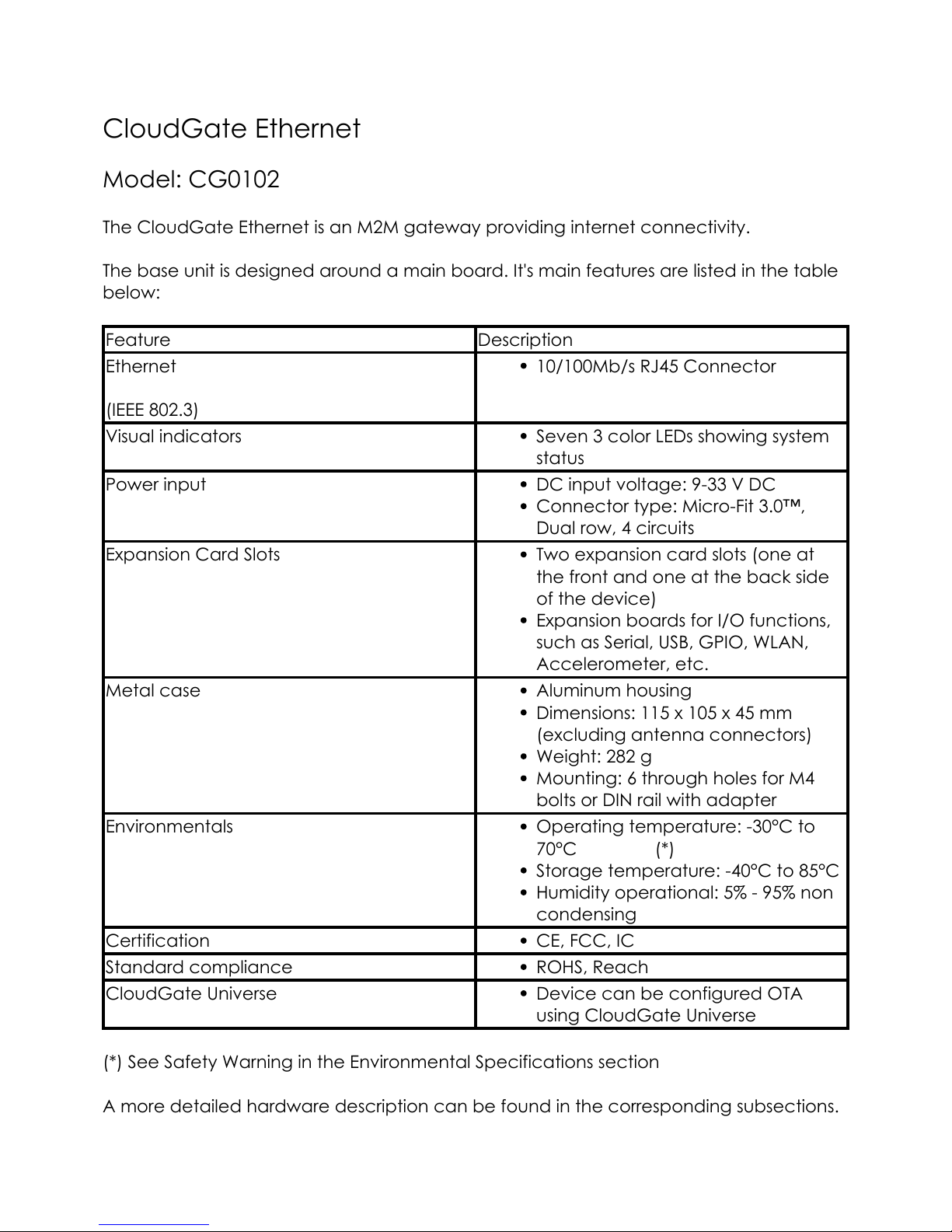
The CloudGate Ethernet is an M2M gateway providing internet connectivity.
The base unit is designed around a main board. It's main features are listed in the table
below:
Feature Description
Ethernet
(IEEE 802.3)
10/100Mb/s RJ45 Connector
Visual indicators Seven 3 color LEDs showing system
status
Power input DC input voltage: 9-33 V DC
Connector type: Micro-Fit 3.0™,
Dual row, 4 circuits
Expansion Card Slots Two expansion card slots (one at
the front and one at the back side
of the device)
Expansion boards for I/O functions,
such as Serial, USB, GPIO, WLAN,
Accelerometer, etc.
Metal case Aluminum housing
Dimensions: 115 x 105 x 45 mm
(excluding antenna connectors)
Weight: 282 g
Mounting: 6 through holes for M4
bolts or DIN rail with adapter
Environmentals Operating temperature: -30°C to
70°C (*)
Storage temperature: -40°C to 85°C
Humidity operational: 5% - 95% non
condensing
Certification CE, FCC, IC
Standard compliance ROHS, Reach
CloudGate Universe Device can be configured OTA
using CloudGate Universe
(*) See Safety Warning in the Environmental Specifications section
A more detailed hardware description can be found in the corresponding subsections.
3
Page 4

A datasheet of the CloudGate Ethernet can be found here.
The CloudGate Ethernet has two expansion card slots that allow to insert a variety of
expansion cards.
Powered by TCPDF (www.tcpdf.org)
4
Page 5
1.8.1. Main Board
The CloudGate Ethernet is designed around a main board. The processor on the main
board controls all the interfaces.
The CloudGate also has two expansion board connectors to allow insertion of
dedicated expansion cards.
The block diagram shows the overview.
Main Board Block Diagram (PDF)
Power Input
V_PWR: min 9V DC, max 33V DC
Internal Power Supply
Power input: V_PWR, min 9V DC, max 33V DC
Stable 3.4V power rail
Reverse polarity protection
Over-voltage protection up to 60V
Current limiter at 1.2A
One-time fuse of 2A
Main Board Processor
Freescale i.MX280 @ 450MHz
64 MB RAM
128 MB Flash memory
Ethernet interface
interfaces to the two expansion board connectors
Primary Expansion Card Slot
The primary expansion card slot is located at the front side of the CloudGate.
It has the following interfaces:
Power supply: V_PWR, 3V4, 3V3
24 Mhz clock signal
Master reset signal
High speed USB interface
High speed OTG USB interface
SDIO interface
5
Page 6
GPIO signals
Serial interface
Secondary Expansion Card Slot
The secondary expansion card slot is located at the back side of the CloudGate.
It has the following interfaces:
Power supply: V_PWR, 3V4, 3V3
24 Mhz clock signal
Master reset signal
High speed USB interface
SDIO interface
GPIO signals
Powered by TCPDF (www.tcpdf.org)
6
Page 7
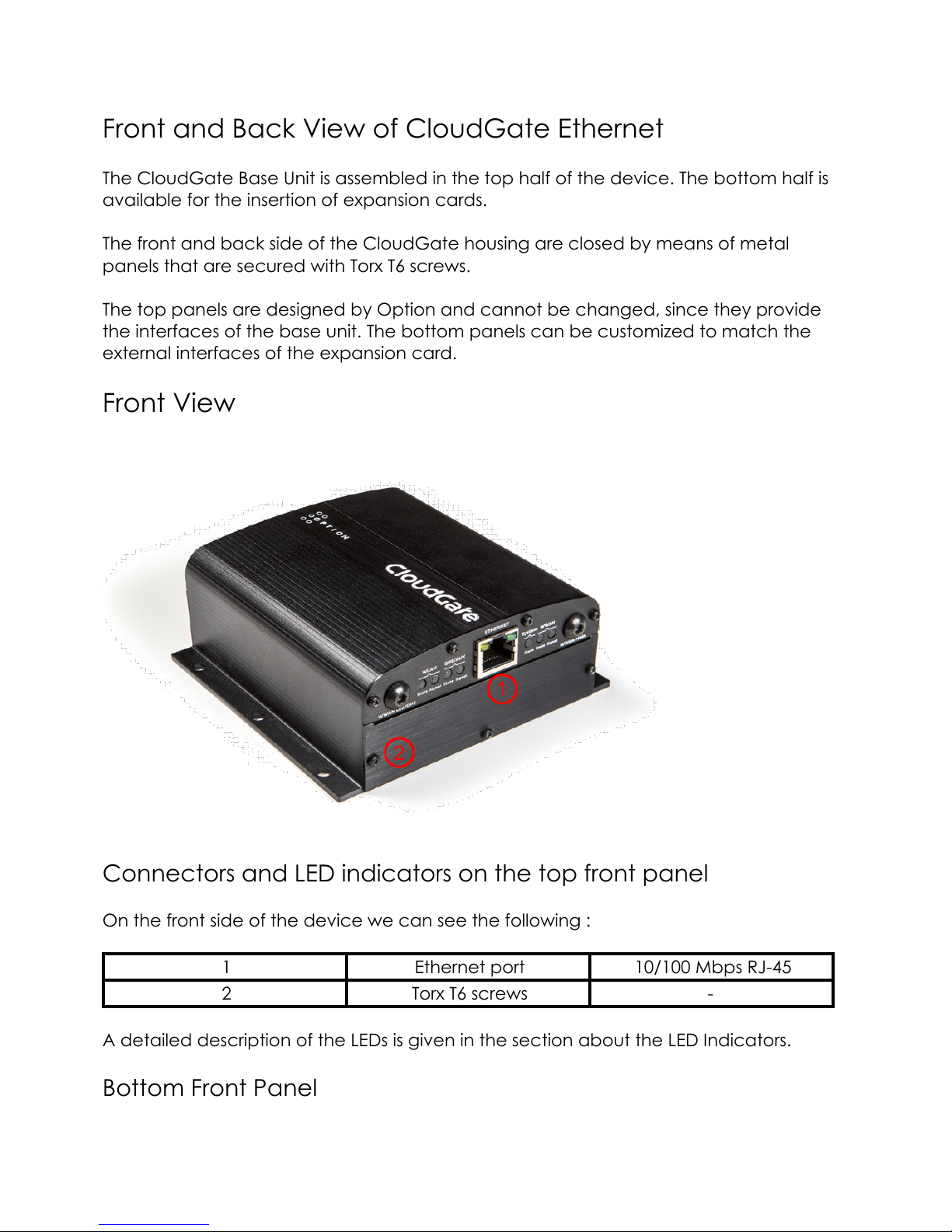
Front and Back View of CloudGate Ethernet
The CloudGate Base Unit is assembled in the top half of the device. The bottom half is
available for the insertion of expansion cards.
The front and back side of the CloudGate housing are closed by means of metal
panels that are secured with Torx T6 screws.
The top panels are designed by Option and cannot be changed, since they provide
the interfaces of the base unit. The bottom panels can be customized to match the
external interfaces of the expansion card.
Front View
Connectors and LED indicators on the top front panel
On the front side of the device we can see the following :
1 Ethernet port 10/100 Mbps RJ-45
2 Torx T6 screws -
A detailed description of the LEDs is given in the section about the LED Indicators.
Bottom Front Panel
7
Page 8
The bottom front panel covers the front expansion slot and has to be removed when
installing a Primary Expansion Card.
Option provides a custom panel for the following primary expansion cards:
Low Cost Serial Card
Industrial Serial Card
Ethernet Switch
Ethernet Switch with PoE
Telematics Card
Breadboard Card
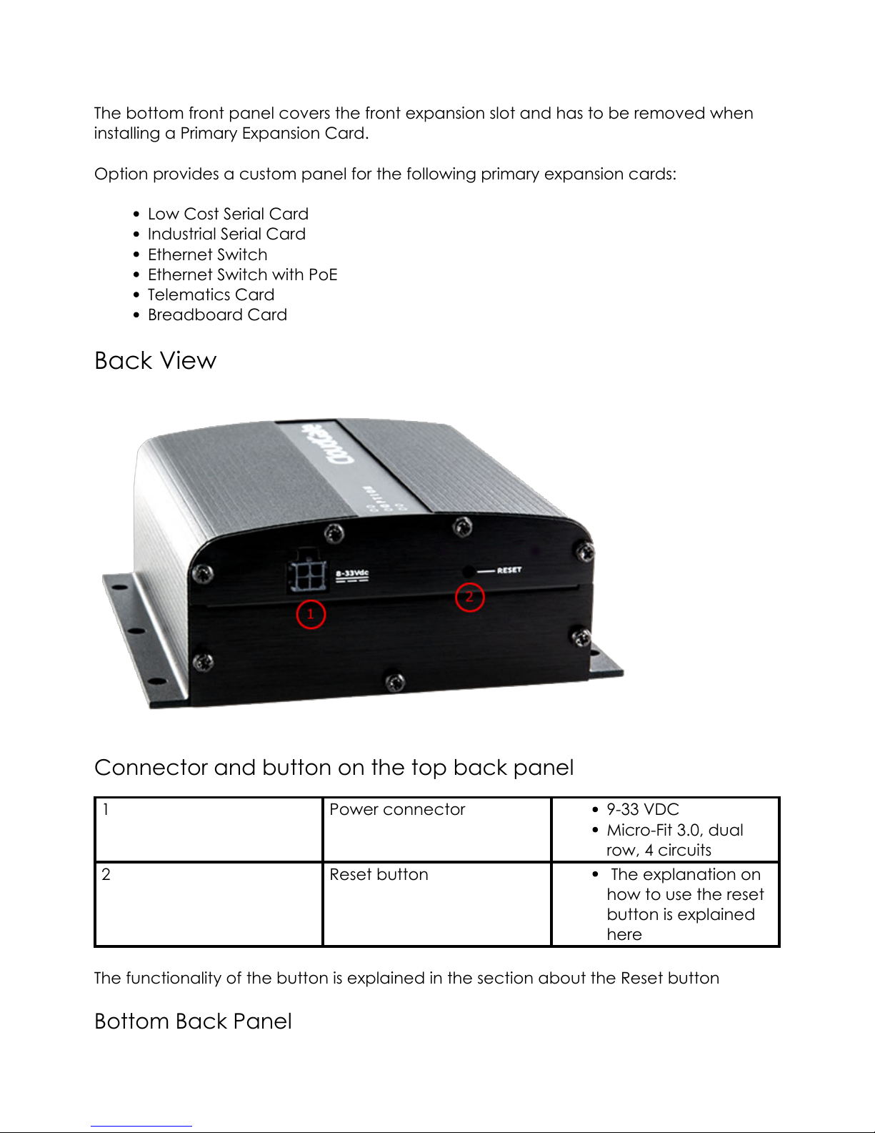
Back View
Connector and button on the top back panel
1 Power connector 9-33 VDC
Micro-Fit 3.0, dual
row, 4 circuits
2 Reset button The explanation on
how to use the reset
button is explained
here
The functionality of the button is explained in the section about the Reset button
Bottom Back Panel
8
Page 9

The bottom back panel covers the back expansion slot and has to be removed when
installing a Secondary Expansion Card.
Option provides a custom panel for the following secondary expansion cards:
WLAN Expansion Card
WLAN Access Point Card
Powered by TCPDF (www.tcpdf.org)
9
Page 10
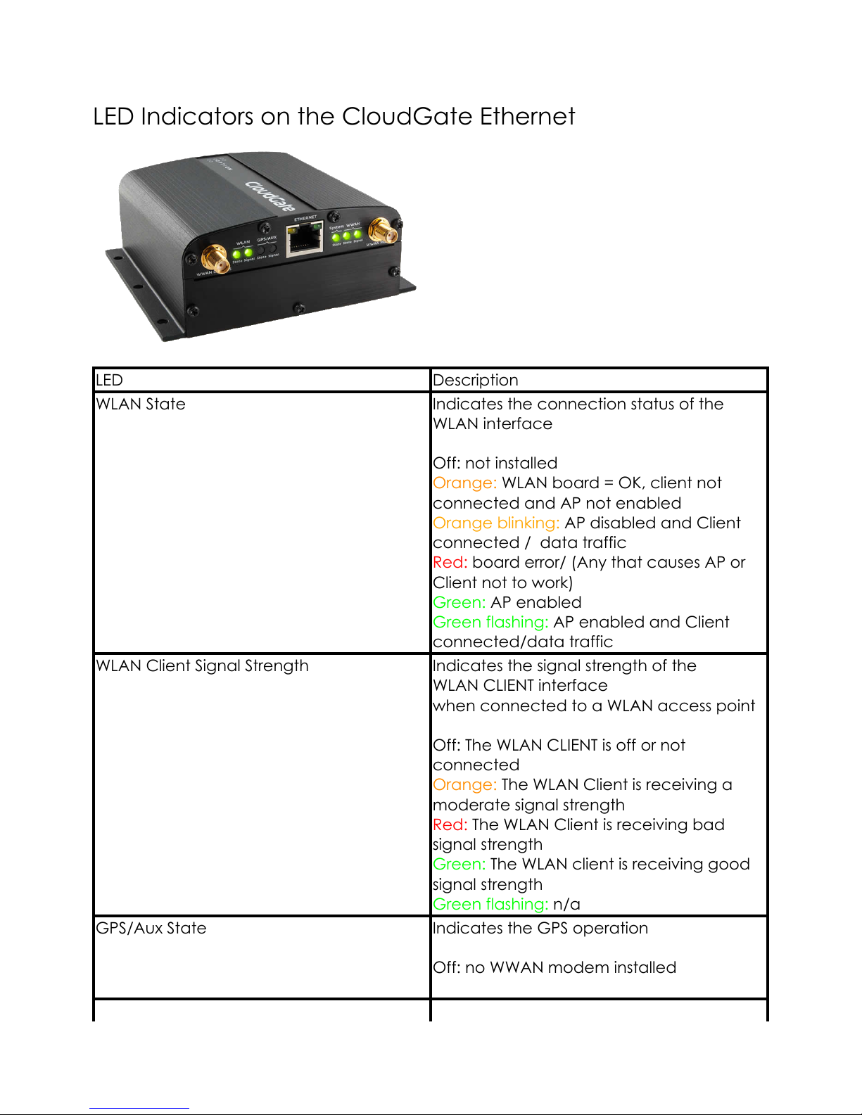
LED Indicators on the CloudGate Ethernet
LED Description
WLAN State Indicates the connection status of the
WLAN interface
Off: not installed
Orange: WLAN board = OK, client not
connected and AP not enabled
Orange blinking: AP disabled and Client
connected / data traffic
Red: board error/ (Any that causes AP or
Client not to work)
Green: AP enabled
Green flashing: AP enabled and Client
connected/data traffic
WLAN Client Signal Strength Indicates the signal strength of the
WLAN CLIENT interface
when connected to a WLAN access point
Off: The WLAN CLIENT is off or not
connected
Orange: The WLAN Client is receiving a
moderate signal strength
Red: The WLAN Client is receiving bad
signal strength
Green: The WLAN client is receiving good
signal strength
Green flashing: n/a
GPS/Aux State Indicates the GPS operation
Off: no WWAN modem installed
10
Page 11

LED Description
GPS/Aux signal strength Indicates the signal strength of the GPS
Off: no WWAN modem installed
System State Indicates successful power on and device
readiness
Off: no power
Orange: booting
Red: error
Green: on
Green flashing: n/a
WWAN State Indicates WWAN or 3G interface
availability and use
Off: no WWAN modem installed
WWAN Signal Strength Indicates WWAN or 3G interface signal
strength
Off: no WWAN modem installed
Powered by TCPDF (www.tcpdf.org)
11
Page 12

1.8.4. Ethernet Interface
This section describes the Ethernet interface on the CloudGate main board.
Ethernet Interface
RJ-45 receptacle tab on top
10/100 Mbps
100BASE-TX
Auto-MDIX
Pinout
Yellow LED:
Active when operating speed is 100 Mbps
Inactive when operating speed is 10 Mbps or when not connected
Green LED:
Active when valid links are detected
Blinks when activity is detected
Inactive when not connected
Pin # Function
1 TX/RX+
2 TX/RX-
3 RX/TX+
4 Not used
12
Page 13

Pin # Function
5 Not used
6 RX/TX-
7 Not used
8 Not used
IMPORTANT: The auto-MDIX feature is always activated on the CloudGate. This feature
automatically detects the required cable connection type (straight or crossed), and
configures the connection appropriately, removing the need for crossover cables.
In order for auto-MDIX to work correctly, auto-negotiation (auto speed and auto
duplex) must be enabled on both sides of the link. Note that auto negotiation is always
active on the CloudGate.
WAN/LAN Switchover Feature
The WAN/LAN switchover feature is a mechanism to maximize the internet connectivity
via the Ethernet port.
The description of the related configuration parameters and the switchover mechanism
itself can be found in the Ethernet Tab section of the CloudGate Setup Guide.
Powered by TCPDF (www.tcpdf.org)
13
Page 14

1.8.5. Power Requirements
Base Unit Power Supply
The symbol on the label at the bottom side of the CloudGate shows the power
requirements:
Input voltage must be between 9V - 33V DC
Internal electronic fuse limits the input current to 1.2A
For the power cable between the external power supply unit and the CloudGate
Option recommends to use a power cable that has a wire thickness of 22 AWG!
SAFETY WARNING
This CloudGate operates on DC power provided by a DC power supply or by an AC
power adapter. Only use power supplies in the range 9-33V DC and make sure the
product is installed near a power outlet that is easily accessible.
When using the KNX card, only use a 24Vdc power supply.
SAFETY WARNING
When using an AC adapter make sure that the ambient temperature doesn’t exceed
the specified temperature limits of the AC adapter.
SAFETY WARNING
The CloudGate is regarded a Class III equipment: this means that the protection against
electrical shock is provided by means of power supplied by an SELV (Safety Extra Low
Voltage) circuit and that the CloudGate does not generate hazardous voltages within
itself.
When using an AC power adapter make sure it provides protection against electrical
shock, class II, and that it is certified for the country where it will be used.
As a reference, the power supply available from Option has the following parameters:
Output voltage 12V DC
Max output current 1A
In case you would like to use an industrial power supply Option recommends the next:
http://www.us.tdk-lambda.com/ftp/Specs/dspa.pdf
It can be sourced through Farnel, Mouser, Digikey, ...
14
Page 15

Power Connector
The power connector is a Micro-Fit connector from Molex (MX-43025-0400)
Power Connector Drawing (PDF)
Power Connector Datasheet (PDF)
Pinout
The following drawing shows the pinout of the power connector, seen from the terminal
side.
Pin # Function
1 Input voltage
2 GND
3 Not connected
4 Not connected
Power Consumption
You can find here a document describing all the different power consumption numbers
Preventing Fuse Overload
15
Page 16

SAFETY WARNING
On old CloudGate models, a huge inrush current caused by capacitors inside the
CloudGate may cause an internal fuse to break. When using an external power supply
with an output voltage higher than 15V, Option recommends using a special cable
which will reduce the amplitude of these charge currents. This cable can be obtained
at your CloudGate distributor.
If the fifth digit of the serial number of the CloudGate is a "C", the CloudGate is an older
model and susceptible to this remark. If the fifth digit is not a "C", the fuse of your
CloudGate will not get broken due to these charge currents.
Powered by TCPDF (www.tcpdf.org)
16
Page 17

1.8.5.1. Internal Power Circuits
The voltage applied by the power adapter to the CloudGate is converted into different
voltage rails on the main board. Two different power circuits make five different voltage
rails.
Dedicated high current power circuit
Provides two different voltage rails which both can deliver high current levels:
V_PWR: At the power adapter input of the CloudGate there is an
overvoltage protection circuit and a current limiter of 1.2A. The V_PWR is
the voltage level behind the current limiter. The protection circuit causes
a little voltage drop lower than 1V.
3V4: the 3V4 is a power rail generated by a dedicated power circuit on
the main board. The 3V4 is used on the main board and is also available
on the expansion boards.
Low power circuit generated by the micro controller
Provides three voltage rails for very limited power:
3V3: A 3.3V power rail provided by the micro controller is used on the
mainboard and also accessible to the expansion boards
1V8: A 1.8V power rail provided by the micro controller and only used on
the main board
1V2: A 1.2V power rail provided by the micro controller and only used on
the main board
Voltage Rail Voltage Usage Max Current
V_PWR Equals the voltage
applied by the
power adapter,
minus the drop over
the protection circuit
Use for power-hungry
devices
Current is limited to
1.2A
3V4 3.4V Powers all standard
digital components
on the expansion
cards
3A maximum of
which the main
board is already
using 1.5A. Only 1.5A
is left for both
expansion cards.
(The sum of both
expansion cards
should be lower than
1.5A)
3V3 3.3V Powers low power
components or level
The DC/DC
Converter is a triple
17
Page 18

translators, e.g.
between I/O signals
from the processor
and circuitery on the
main board or on
the expansion cards
output buck
converter (3V3, 1V8
and 1V2). The
maximum output
current capability of
each output of the
converter is
dependent on the
loads on the other
two outputs.
1V8 1.8V Internal use on the
main board only
Internal use only
1V2 1.2V Internal use on the
main board only
Internal use only
Internal Power Circuits Block Diagram
18
Page 19

Powered by TCPDF (www.tcpdf.org)
19
Page 20

1.8.6. Reset Button
On the back side of the unit there is a reset button behind the hole in the top panel
(indicated by the "2" in the picture above).
This button allows to restart the unit or to reset it to the factory settings:
press and hold for less than ten seconds to reset the unit to the last working
settings,
press and hold for ten seconds or more to reset the unit to factory settings.
Powered by TCPDF (www.tcpdf.org)
20
Page 21

1.8.7. Mechanical Drawings of the CloudGate Ethernet
3D file of the CloudGate Ethernet.
3D file of the front plate of the expansion cards
(1)
As there is no WWAN module inside, there are no RF connectors on the front plate of
the CloudGate Ethernet.
Below you can find the dimensions of the CloudGate.
21
Page 22

22
Page 23

The 6 mounting holes in the CloudGate housing allow mounting on a wall or on a DIN
rail. See the details in the "Mounting" section of the CloudGate Installation Guide.
Note 1:
The front plate for the expansion cards, both at the front and at the back side of the
CloudGate, are identical.
Powered by TCPDF (www.tcpdf.org)
23
Page 24

1.8.7.1. IP-65 Requirements
Below you can find the parts for the encasing which are needed to fulfill the
requirements for IP-65.
All these parts can be ordered by TAKACHI:
1x box BCAK 203013G or BCPK 203013S,
1x plate BMP 2030P,
1 x screws (20pcs) MT4-8T,
1x bracket (2x4 pcs) BLF-2G(PC-GF) or CK-26P (metal SS)
3x cable gland MG-12S (3 inputs)
24
Page 25

Powered by TCPDF (www.tcpdf.org)
25
Page 26

Environmental Specifications
Operating temperature: -30°C to 70°C (*) see Safety Warning below
Storage temperature: -40°C to 85°C
Humidity operational: 5% - 95% non condensing
Operating altitude: up to 2000m
Safety Warning
When the device is installed in a location where the environmental temperature can
rise above 60°C, the temperature of the surface might reach high values and therefore
under these conditions the user needs to warned in order to prevent accidental
contact. For this purpose the device has to be installed in a restricted access location
and a warning sticker, in accordance with IEC 60417-5041 (DB:2002-10), must be
applied on a visible part of the unit.
Powered by TCPDF (www.tcpdf.org)
26
Page 27

1.8.9. Shock Resistance
The next tests have been performed on the CloudGate and passed:
• EUT state: operational
• Frequency range: 10 … 2000Hz
• Overall acceleration: 3.6Grms
• Crest Factor: 3
• Orientation: 3 axis, X / Y / Z
• Test duration: 94 hours / axis
• Profile: See PSD table on 'additional info' sheet
Test Details Spec number
Resonance search and
dwell
(Search for critical
resonances and stress
these to verify the
reliability of the EUT.)
• EUT state: operational
• Frequency range: 10 … 2000Hz
• Overall acceleration: 3.6Grms
• Crest Factor: 3
• Orientation: 3 axis, X / Y / Z
• Test duration: 94 hours / axis
• Profile: See PSD table on 'additional
info' sheet
IEC 60068-2-6
Vibration endurance
(Simulate rough
conditions over lifetime.)
ISO 16750-3 IEC 60068-2-53
Shock Vibration (Bump)
(Simulate rough
handling.)
• EUT state: operational
• Acceleration: 10gn
• Pulse width: 11ms
• Waveform: Half-sine
• Amount of bumps: 100 / axis
• Orientation: 3 axis, X / Y / Z
IEC60068-2-27
Guided drop test
(Simulate impact caused
by dropping the device.)
• EUT state: Non-operational
• Drop height: 150cm
• Drop surface: concrete floor
• Amount of impacts: 6 (1 per
orientation)
• Orientation: 6 axis, X+/X- / Y+/Y- /
Z+/Z-
IEC60068-2-31
Powered by TCPDF (www.tcpdf.org)
27
Page 28

Certification information for CloudGate Ethernet
Model: CG0102
This page offers an overview of the country certifications and operator approvals
obtained per region. This CloudGate model is approved for use in the countries listed
below. For use in other countries, please consult your sales contact.
Canada
European Economic Area (Austria, Belgium, Bulgaria, Croatia, Cyprus, Czech
Republic, Denmark, Estonia, Finland, France, Germany, Greece, Hungary,
Iceland, Ireland, Italy, Latvia, Liechtenstein, Lithuania, Luxemburg, Malta,
Netherlands, Norway, Poland, Portugal, Romania, Slovakia, Slovenia, Spain,
Sweden, United Kingdom)
Switzerland
Turkey
United States
Before installing your CloudGate device, read the Safety Guidelines section in the
CloudGate Installation Guide carefully. Not following these guidelines can cause harm
to the CloudGate, yourself or other persons.
Canada
The CloudGate Ethernet can be used in Canada and complies with the applicable
Industry Canada regulations.
The CloudGate Ethernet can be used in Class I Div 2 Hazardous Locations. Click here for
conditions for use.
INDUSTRY CANADA REGULATIONS
This device complies with Industry Canada license-exempt RSS standard(s). Operation is
subject to the following two conditions:
(1) this device may not cause interference, and
(2) this device must accept any interference, including interference that may cause
undesired operation of the device.
REGULATIONS INDUSTRIE CANADA
Le présent appareil est conforme aux CNR d'Industrie Canada applicables aux
28
Page 29

appareils radio exempts de licence. L'exploitation est autorisée aux deux conditions
suivantes:
(1) l'appareil ne doit pas produire de brouillage, et
(2) l'utilisateur de l'appareil doit accepter tout brouillage radioélectrique subi, même si
le brouillage est susceptible d'en compromettre le fonctionnement.
European Economic Area
The CloudGate Ethernet complies with the essential requirements of the EMC directive
2014/30/EU and the Low Voltage directive 2014/35/EU issued by the Commission of the
European Union and carries the CE mark. The product can be used in the following
countries of the European Economic Area: Austria, Belgium, Bulgaria, Cyprus, Czech
Republic, Denmark, Estonia, Finland, France, Germany, Greece, Hungary, Iceland,
Ireland, Italy, Latvia, Liechtenstein, Lithuania, Luxembourg, Malta, Netherlands, Norway,
Poland, Portugal, Romania, Slovakia, Slovenia, Spain, Sweden and the United Kingdom.
The R&TTE declaration of conformity can be downloaded here
Waste from Electrical and Electronic Equipment (WEEE)
Attention: Your product is marked with this symbol. Electrical and electronic
equipment should not be disposed of with general household waste. There is a
separate collection system for these items.
Please contact your supplier for information on their disposal policy. You may be
charged for the costs of take-back and recycling. In some countries, small products in
small quantities may be disposed of at designated collection facilities. Please contact
your local authority for details.
Switzerland
The CloudGate Ethernet carries the CE mark and can be used in Switzerland.
29
Page 30

Turkey
The CloudGate Ethernet carries the CE mark and can be used in Turkey.
United States
The CloudGate Ethernet can be used in the USA and complies with the applicable FCC
rule parts.
The CloudGate Ethernet can be used in Class I Div 2 Hazardous Locations. Click here for
conditions for use.
FCC REGULATIONS
This device complies with Part 15 of the FCC rules. Operation is subject to the following
two conditions:
(1) this device may not cause harmful interference, and
(2) this device must accept any interference received, including interference that may
cause undesired operation.
Federal communications commission notice
This equipment has been tested and found to comply with the limits for a Class A digital
device, pursuant to part 15 of the FCC Rules. These limits are designed to provide
reasonable protection against harmful interference when the equipment is operated in
a commercial environment. This equipment generates, uses, and can radiate radio
frequency energy and, if not installed and used in accordance with the instruction
manual, may cause harmful interference to radio communications. Operation of this
equipment in a residential area is likely to cause harmful interference in which case the
user will be required to correct the interference at his own expense.
Modifications
Any changes or modifications made to this device that are not expressly approved by
Option could void the user's authority to operate the equipment.
Powered by TCPDF (www.tcpdf.org)
30
Page 31

Class I Div 2 Hazardous Locations
Model: CG0102
Expansion card models CG2101, CG1102, CG1106, CG3102
This page offers information on using your CloudGate product in Class I Div 2 Hazardous
Locations in the countries listed below. For use in other countries, please consult your
sales contact.
Please read the safety guidelines carefully. Not following these guidelines can cause
harm to the CloudGate, yourself or other persons.
Canada & United States
The CloudGate Ethernet can be used in Canada and the United States and was tested
under following standards:
CSA C22.2 No. 213-M1987 "Non-incendive electrical equipment for use in class I,
division 2 hazardous locations"
ANSI/ISA-12.12.01-2013 "Nonincendive Electrical Equipment for Use in Class I and
II, Division 2 and Class III, Divisions 1 and 2 Hazardous (Classified) Locations"
The above mentioned model can only be used in Hazardous Locations when marked
with the 'MET RECOGNIZED" logo. The above mentioned expansion card models can
only be used when marked with the text "C1D2" on the label. Other existing CloudGate
models and other expansion cards that are not present in the list above, shall not be
used in hazardous locations.
This equipment is suitable for use in Class I, Division 2, Groups A, B, C, D or non-
hazardous locations only.
Hazardous locations safety guidelines
Normal locations safety guidelines
Powered by TCPDF (www.tcpdf.org)
Page 32

Powered by TCPDF (www.tcpdf.org)
 Loading...