

Optimus XL-150 Owner's Manual

12-2015.fm Page 1 Tuesday, July 13, 1999 3:47 PM
Cat. No. 12-2015
OWNER’S MANUAL
Please read before using this equipment.
XL-150
High Power 4-Channel
Stereo Amplifier

g
12-2015.fm Page 2 Tuesday, July 13, 1999 3:47 PM
FEATURES
Your Optimus XL-150 High Power 4Channel Stereo Amplifier is designed
to give added punch and power to your
vehicle’s existing autosound system.
The amplifier produces up to 40 watts
(front) and 110 watts (rear) per c hannel of clean, powerful sound at all audio frequencies with minimum distortion. You can connect your autosound system’s low-level or speakerlevel outpu t s to this amplifier.
Its features include:
14K Gold-Plated Noise-Isolated
let you con-
Low-Level Input Jacks
—
nect low-level (preamplifier) signal inputs to match your autosound system’s output for the best high-fidelity
performance.
14K Gold-Plated Speaker Ter min als
designed for low impedance, high
—
conductivity, and minimum corrosion,
to provide the highest signal transfer
and lowest sound distortion.
eliminates
Mute Turn On Circuit
—
the thump you hear when you turn on
some amplifiers.
lights when power
Power Indicator
—
is supplied to the amplifier.
protects the amplifier by
Auto-Off
—
temporarily shutting do wn i f it gets t oo
hot or it detects an input overload. The
amplifier restarts automatically when it
cools or the problem is corrected.
lights if the
Protection Indicator
—
amplifier shuts down its rear channel.
distorts
Short Circuit Protection
—
the amplifier’s sound if any output
channel shorts, alerting you to turn off
the autosound system.
let you adjust
Input Level Controls
—
the level of the audio signals that enter
the amplifier.
Automatic Power Switchin
— can
automatically turn the amplifier on or
off when you turn your autosound system on or off (depending on how you
hook up the amplifier).
© 1997 Tandy Corporation.
Optimus and RadioShack are registered trademarks used by Tandy Corporation.
All Rights Reserv ed .
2

g
g
g
12-2015.fm Page 3 Tuesday, July 13, 1999 3:47 PM
CONTENTS
Preparation ........................................................................................................... 4
Supplied Hardware ......................................................................................... 4
Before You Begin the Installation .................................................................... 4
Choosing a Mounting Location ................................................................. 5
Preparing the Mounting Area .................................................................... 5
Routing Cables and Wires ........................................................................ 5
Installation Order ............................................................................................. 5
Before You Make the Connections .................................................................. 6
Connecting Ground and Switched/Primary Power ...........................................7
Connectin
Low-Level Inputs ........................................... ....... .. .......... ....... ....... ....... ..... ..... 9
High-Level (Speaker Wire) Inputs ................................................................. 11
Connecting Speakers .................................................................................... 14
Completin
Testing the Connections ................................................................................ 16
Mounting the Amplifier .................................................................................. 16
Operation ............................................................................................................ 18
Turning On the Amplifier ............................................................................... 18
Adjusting the Audio Level ............................................................................. 18
Troubleshootin
Care and Maintenance ...................................................................................... 21
The FCC Wants You to Know ....................................................................... 21
Replacing a Fuse .......................................................................................... 22
Specifications .................................................................................................... 24
Inputs ............................................................................................... 9
Four Speaker Outputs . ........................................................................... 12
Two Speaker Outputs ............................................................................. 13
Preparing the Speaker Wires ................................................................. 14
Connecting the Speakers to the Amplifier ...............................................15
the Installation .............................................................................. 16
................................................................................................ 19
Replacing the SFE-Type Fuse ................................................................ 22
Replacing the Blade-Type Fuse ............................................................. 23
3

12-2015.fm Page 4 Tuesday, July 13, 1999 3:47 PM
PREPARATION
SUPPLIED HARDWARE
Your amplifier comes with the following items. Be sure you locate everything shown
before you store or dispose of the packing materials.
(illustration - show all amplifier parts, wires, and hardware)
BEFORE YOU BEGIN THE INSTAL LATION
Before you install your amplifier, rea d all the instructions in this owner’s manual.
And, you should be able to answer all of these questions about your vehicle’s electrical and autosound systems.
• Does my vehicle have an autosound system, such as a car stereo or CD
player, already installed? (You must have a n existing aut osound system to use
this amplifier.)
• How do I connect a wire to the fuse box?
• Which of the autosound system’s wires is the power wire?
• Which of the autosound system’s terminals are low-level outputs and which are
high-level (speaker) outputs?
Also, be aware that installation in your v ehicle might require cutting or modifying
your vehicle.
4

g
123
12-2015.fm Page 5 Tuesday, July 13, 1999 3:47 PM
Choosing a Mounting
Location
A good location for mounting the amplifier is in your vehicle’s trunk. Wh erever you decide t o moun t it, choos e a
location that:
• Does not interfere with the vehicle’s operation
• Lets you drill mounting hole s without damaging other vehicle components
• Allows enough space around the
cooling fins for proper airflow and
cooling
• Lets you easily see the ampl ifier’s
POWER and PROTECTION indicators
Warnin
The amplifier gets very hot
:
while it is on. Do not touch the amplifier
or place flammable objects near it
while it is on.
Preparing the Mounting Area
Before you mount the a mplifier, make
sure you have all the materials you
need, such as an adapter harness,
additional wire, shielded audio cables,
and 16- or 18-gauge marked or colorcoded wires.
Then con firm that the amplifier fits in
your vehicle’s available mounting area. This amplifier requires a 2
high by 10 -inch wi de by 12
(5.2 ¥ 25.4 ¥ 30.8 cm) mounting area
with adequate ventilation space.
1
/16-inch
1
/8-inch deep
Routing Cables and W ires
Avoid routing the connection cables
and any speaker wires near moving
parts or sharp edges. You can usually
route wires and cables along the wiring
channel b eneath the vehic le’ s door facings by carefully removing the molding
that holds the carpet in place. After
routing the cables and wires, replace
the molding.
INSTALLATION ORDER
For trouble-free installation, simply follow the sections in this Owner’s Manual in order. First, temporarily connect
the amplifier to:
Ground and power
Your autosound system’s outputs
Your speakers
Then test the connections. When you
verify that everything works as expected, disconnect the amplifier , mount it in
your vehicle, and reconnect it.
Caution:
nections in the order shown, d amage
to the amplifier and your autosound
system is possible if any wire connections are made incorrectly.
Note:
each wire you plan to connect with the
name of the terminal you will connec t
it to.
If you do not make the con-
For easier installation, mark
5
12-2015.fm Page 6 Tuesday, July 13, 1999 3:47 PM
BEFORE YOU MAKE THE
CONNECTIONS
The supplied connection cables include all the lead wires you need to
connect the amp l ifier to ground, power,
and your existing autosound system.
Important:
• Do not cut these wires. If you cut
any wire, you cannot obtain a
refund or exchange on t his product. However, RadioShack
provide warranty service if you cut
a wire and find the product is
defective.
• If the connectors on your vehicle’s
autosound system are not compatible with the amplifier’s connectors, you might need an
adapter harness to complete the
connections. RadioShack stores
sell adapter harnesses for most
vehicles.
will
Cautions:
• For added safety and to protect
your amplifier and autosound system, disconnect the cable from
your vehicle’s negative (–) battery
terminal before you begin.
• Be sure your front speakers can
handle as much as 20 watts per
channel and your rear speakers
as much as 55 wat ts per channel
of power. Each speaker must
have an impedance of at least 4
ohms. Your local RadioShack
store carries a full line of speakers.
You might need additional wire, depending on your individual autosound
system, to complete the connections.
Your local RadioShack sto re carries a
full line of wire a nd wire managem ent
accessories.
6
To make it easier to gauge wire length
and connect the amplifier, temporarily
place the amplifier as close as possible
to the selected mounting location.
12-2015.fm Page 7 Tuesday, July 13, 1999 3:47 PM
CONNECTING GROUND AND
SWITCHED/PRIMARY POWER
Follow these steps to connect the amplifier to ground, switched power, and
primary power.
1. If you have not done so already,
disconnect the cable from your
vehicle’s negative (–) battery terminal.
2. Use a screwdriver to connect the
spade end of the supplied black
ground wire to the am pl ifier ’s
(ground) terminal.
3. Connect the black ground wire’s
other end to a chassis ground,
such as a metal bolt attached to a
metal part of the vehicle’s frame.
Be sure the bolt is not insulated
from the chassis by a plastic part.
4. Use a screwdriver to connect the
spade end of the supplied blue/
white wire to the amplifier’s
(remote power) terminal.
GND
REM
7

12-2015.fm Page 8 Tuesday, July 13, 1999 3:47 PM
5. Connect the blue/white wire’s
other end to your autosound system’s switched power lead using
one of the supplied twist-on terminal connectors.
(illus)
This connection turns on the
amplifier when you turn on the
autosound system, and turns off
the amplifier when you turn off the
autosound system. This prevents
your vehicle’s battery from being
drained if you leave your am plifier
on when you turn off your autosound system.
If your autosound system does
not have a switched power lead,
connect the blue/white wire’s
other end to a point in your vehicle’s fuse block that has power
only when you turn on the ignition
or turn the key to ACC.
This connection turns on the
amplifier when you turn on the
ignition or turn the key to ACC,
and turns off the amplifier when
you turn off the ignition. This p revents your vehicle’s battery from
being drained if you leave your
amplifier on when you turn off the
ignition.
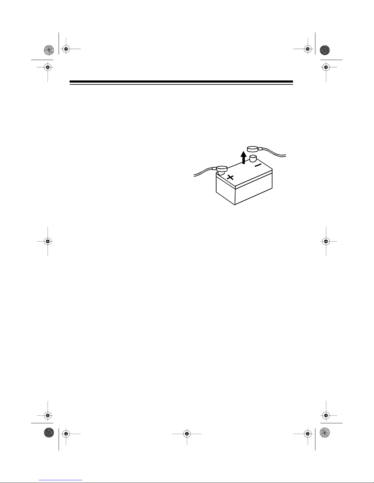
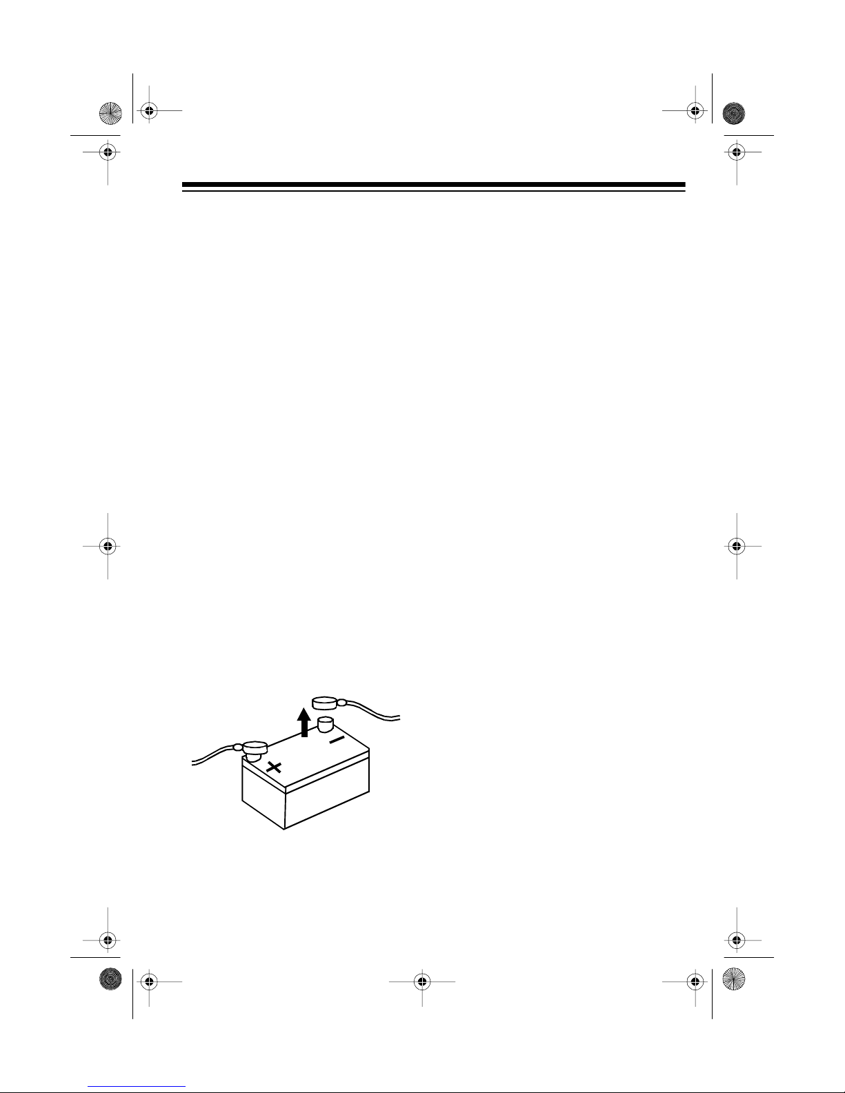
6. Use a screwdriver to connect the
spade end of the supplied red
power cable (with in-line fuse
holder) to the amplifier ’s
+ 12V
ter-
minal.
7. Connect the other end of the red
power cable to your vehicle’s positive (+) battery terminal as shown.
Then tighten the terminal.
(illus)
Caution:
Due to the amplifier’s
high current requirement, you
must
connect the red power
cable’s fused end directly to the
vehicle’s positive (+) battery terminal or damage to your vehicle’s
wiring could result.
Do not reconnect your vehicle’s negative (–) battery cable yet.
8

12-2015.fm Page 9 Tuesday, July 13, 1999 3:47 PM
CONNECTING INPUTS
LOW-LEVEL INPUTS
You can connect your auto sound system’ s low-level line out jacks to the amplifier’s low- leve l l ine in jacks.
If your autosound system does
(Speaker Wire) Inputs” on Page 11 to connect your amplifier.
1. Temporarily place the amplifier as close as possible to the selected mou nting
location.
If your autosound system has four separate line out jacks
2.
sound system to the amplifier as shown:
not
have low-level line out jacks, see “High Level
, connect the auto-
(illus)
For the best results, use shielded audio cables such as Cat. No. 42-2368
Note:
(not supplied).
9
 Loading...