

Page 1
9I010UP 21/12/10
Page 2

Page 3
Page 4

UP-67ETH, UP-127ETH,
UP-247ETH, UP-367ETH
Digital power unit
UP-x7ETH version 1.1
4
List of contents
1. INTRODUCTION ................................................................................................................... 6
2. BLOCK DIAGRAM ................................................................................................................. 7
3. FRONT INDICATORS AND CONTROLS .................................................................................. 8
4. REAR ELEMENTS AND CONNECTIONS .................................................................................. 9
4.1. Connection to the 230 V AC mains supply .................................................................. 10
4.2. Mains fuse ............................................................................................................. 10
4.3. Ventilation output ................................................................................................... 10
4.4. Input/output contacts ............................................................................................. 10
4.5. Battery power supply input ...................................................................................... 10
4.6. Ground to chassis connection ................................................................................... 10
4.7. FAIL relay ............................................................................................................. 11
4.8. Loudspeaker line outputs ......................................................................................... 11
4.9. Paging security auxiliary relay .................................................................................. 12
4.10. USB input for pre-recorded messages in MP3 format ................................................ 12
4.11. Emergency (EMG) volume .................................................................................... 12
4.12. PRE OUT volume ................................................................................................. 12
4.13. Emergency input (EMERGENCY IN) ........................................................................ 12
4.14. Priority input (PRIORITY IN) ................................................................................. 14
4.15. Program input (PROGRAM IN) ............................................................................... 15
4.16. MAIN IN ............................................................................................................ 15
4.17. PRE OUT ............................................................................................................ 15
4.18. MAIN IN LINK ..................................................................................................... 16
4.19. RS-485 ADDRESS DIP switch ................................................................................ 17
4.20. RX and TX indicators ........................................................................................... 17
4.21. RS485 IN connector ............................................................................................ 17
4.22. RS485 OUT connector .......................................................................................... 17
4.23. RS485 ON/OFF ................................................................................................... 17
4.24. ETHERNET A input 10 Mb, ACT and LINK LED indicators ............................................ 19
4.25. ETHERNET B input 10 Mb, ACT and LINK LED indicators ............................................ 19
4.26. ETHERNET A connector ........................................................................................ 19
4.27. ETHERNET B connector ........................................................................................ 19
4.28. IP ADDRESS DIP switches .................................................................................... 19
5. LOCAL PRE-RECORDED MESSAGES ..................................................................................... 20
5.1. Pre-recorded messages resident in the MP3 circuit memory .......................................... 20
5.1.1. Characteristics ........................................................................................... 20
5.1.2. Transfer of messages to the MP3 memory of the amplifier ................................ 20
5.1.3. Activation of messages in the MP3 memory of the amplifier .............................. 21
Page 5

UP-67ETH, UP-127ETH,
UP-247ETH, UP-367ETH
Digital power unit
UP-x7ETH version 1.1
5
5.2. Pre-recorded messages resident in the Flash memory of the Coldfire circuit (WAV) .......... 21
5.2.1. Characteristics ........................................................................................... 21
5.2.2. Transfer of messages to the Coldfire Flash memory ......................................... 22
5.2.3. Activation of messages in the Coldfire Flash memory of the amplifier ................. 22
6. INSTALLATION OF AN AMPLIFIER ..................................................................................... 23
6.1. Configuration of the amplifier in the installation by means of the P.A. Manager software ... 23
6.2. Power unit configuration parameters ......................................................................... 24
6.2.1. Configuration of the General tab ................................................................... 24
6.2.2. Configuration of the Audio tab ...................................................................... 27
6.2.3. Configuration of the I/O Contacts (Input/Output Contacts) tab .......................... 29
6.2.4. Configuration of the Temperature Control tab ................................................. 34
6.3. Connecting the equipment in the installation structure ................................................. 35
6.4. Connection to the installation network ....................................................................... 35
6.5. Sending configurations to the unit ............................................................................. 35
6.6. Configuration of the Automatic Level Control tab ......................................................... 36
6.7. Configuration of the Surveillance tab ......................................................................... 39
6.7.1. Emergency input surveillance ....................................................................... 40
6.7.2. Loudspeaker Line surveillance ...................................................................... 41
6.7.3. Monitoring ................................................................................................. 44
6.7.4. Scheduling of line surveillance ...................................................................... 44
6.8. Configured parameters edition ................................................................................. 45
7. CHANGE OF THE UNIT IP ADDRESS BY SOFTWARE ............................................................ 45
8. OPERATIONS FROM THE P.A. MANAGER SOFTWARE .......................................................... 47
8.1. Setting the zone volume .......................................................................................... 47
8.2. Activation and setting of the graphic equaliser ............................................................ 47
8.3. Activation and setting of the parametric equaliser ....................................................... 48
8.4. Assigning the music program to the zone ................................................................... 48
8.5. Playback of a local pre-recorded message .................................................................. 48
9. SOFTWARE CONFIGURATIONS. DEFAULT VALUES ............................................................. 49
10. TECHNICAL SPECIFICATIONS ............................................................................................ 50
11. NETWORK SPECIFICATIONS .............................................................................................. 51
12. SOFTWARE AND FIRMWARE VERSIONS ............................................................................. 53
13. DOCUMENT VERSION TRACKING ....................................................................................... 53
14. GUARANTEE ....................................................................................................................... 54
Page 6

UP-67ETH, UP-127ETH,
UP-247ETH, UP-367ETH
Digital power unit
UP-x7ETH version 1.1
6
1. INTRODUCTION
The UP-367ETH, UP-247ETH, UP-127ETH and UP-67ETH models are digital amplifiers with power ratings
of 360, 240, 120 and 60 watts RMS respectively.
Suitable for use with Public Address systems, emergency announcements, background music and
reproduction of speech, they are remarkably strong and reliable.
They support the broadcast of music and announcements via streaming through an IP network, in
addition to control data and equipment configuration.
Principal characteristics:
Digital audio and control data by means of IP
connection (UDP/IP Multicast).
Double Ethernet connection for installations
with redundant network systems.
Operation in stand-alone mode or with P.A.
Manager control software.
Surveillance of equipment operation by means
of P.A. Manager software and/or basic TELNET
functions.
IP address configuration:
o By means of a DIP switch, facilitating the
replacement of equipment in an
installation.
o In Flash memory, through software.
Constant notification (IP) of the equipment
status by means of a heart beat.
DSP functions for the digital channels: control
of volume, bass, treble, graphic equaliser and
parametric equaliser.
Graphic equaliser and parametric equaliser.
Loudspeaker line surveillance (impedance
measurement).
Thermal protection:
o Alarm notification with user-configurable
threshold.
o Automatic disconnection (temperature set
by hardware).
Fan control with user-configurable thresholds.
Equipped with Fail Safe Relay for surveillance
of amplifier activity.
Pre-recorded messages resident in the
amplifier, located in:
o Flash memory (remotely updateable by
IP).
o MP3 memory, locally updateable through
USB connection.
Emergency input:
o Live voice audio (with critical path
surveillance).
o MP3 local message activation contacts,
with cascade priority:
1. Live voice message.
2. Pre-recorded evacuation message.
3. Pre-recorded warning message.
o Contact status surveillance, detecting
open circuit, short circuit, standby and
activation.
Input/output contacts configurable for
auxiliary functions (activation of emergency
messages, subdivision of zones…).
RS485 connection for control of peripherals
(noise sensors…).
Automatic level control functions.
Keypad lock option, avoiding accidental
pressing of keys.
Local analog input channels: Emergency,
Priority and Program.
Low impedance (4-8-16 ohms) and high
impedance (50-70-100 V) loudspeaker line
output.
Protection against short circuit / overload in
the loudspeaker line.
They occupy two units of height in 19” Rack
cabinets.
Paging security auxiliary relay.
Battery power supply input (24 V DC).
Page 7
UP-67ETH, UP-127ETH,
UP-247ETH, UP-367ETH
Digital power unit
UP-x7ETH version 1.1
7
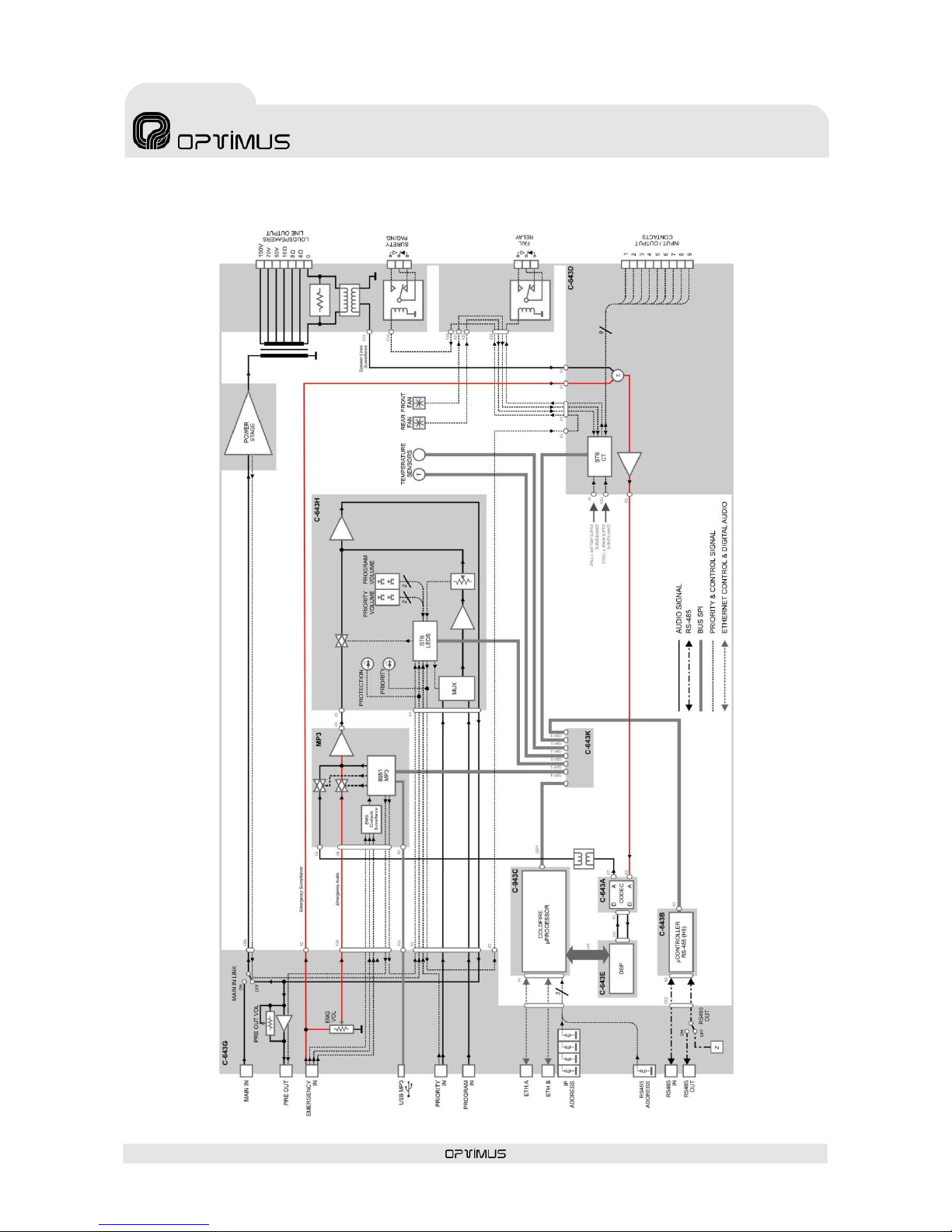
2. BLOCK DIAGRAM
Page 8

UP-67ETH, UP-127ETH,
UP-247ETH, UP-367ETH
Digital power unit
UP-x7ETH version 1.1
8
____________________________________
1
The front volume controls do not affect the digital audio signal that
reaches the amplifier via IP. The volume of the digital signal is
controlled by means of the P.A. Manager software or from the
DC-600ETH / FC-600ETH desk.
The EMERGENCY analog input is not affected by the front volume
controls.
3. FRONT INDICATORS AND CONTROLS
(1) OUTPUT LEVEL indicator
Indicates the power supplied to the loudspeaker
line. The LED marked 0 dB indicates the point at
which the amplifier provides maximum power.
(2) PROGRAM volume level indicator
Indicates the volume level of the PROGRAM
input.
(3) PROGRAM + - volume controls
They control the audio volume of the PROGRAM1
local analog signal input.
(4) PRIORITY + - volume controls
They control the audio volume of the PRIORITY
analog signal input.
(5) PRIORITY volume level indicator
Indicates the volume level of the PRIORITY input.
(6) PRIORITY indicator
It lights:
a) When an announcement that comes from the
PRIORITY analog input is played.
b) When an announcement that comes from the
EMERGENCY analog input is played.
c) When an announcement configured as
PRIORITY that comes from one of the ETH
inputs is played.
d) When a pre-recorded message from the
internal Flash memory of the amplifier is
played.
e) When a pre-recorded message from the MP3
memory is played.
(7) RS485 RX – TX indicators
These indicate reception (RX) or transmission
(TX) of data through the RS485 port of the UPETH.
(8) PROTEC. (PROTECTION) indicator
Lights when the internal protection of the
amplifier is in operation. It can be activated due
to an overload or short circuit in the loudspeaker
line or due to an excessive temperature inside
the amplifier.
(9) ETH A (ETHERNET A) indicators
RX: When lit, it indicates that data is being
received through the ETHERNET A input.
TX: When lit, it indicates that data is being
transmitted through the ETHERNET A input.
10 Mbps: Indicates the transmission speed
of the IP network (lit: 10 Mbps; unlit: 100
Mbps. The use of a transmission speed of 100
Mbps is highly recommended).
LINK: Indicates connection to the network
through the ETHERNET A input.
(10) ETH B (ETHERNET B) indicators
These serve the same purpose as the ETHERNET
A indicators, applied in this case to ETHERNET B.
(11) Ventilation input
This input must not, under any circumstances, be
obstructed.
(12) ON / OFF indicator
Lights up when the amplifier is operating,
whether by Mains supply or Battery.
(13) ON / OFF switch
Switch for turning on the amplifier. If the
amplifier is operating by battery, this switch has
no effect.
Figure 1
Page 9

UP-67ETH, UP-127ETH,
UP-247ETH, UP-367ETH
Digital power unit
UP-x7ETH version 1.1
9
4. REAR ELEMENTS AND CONNECTIONS
(1) Connection to the 230 V AC mains supply
(2) Mains fuse
(3) Ventilation output (only UP-127ETH,
UP-247ETH and UP-367ETH)
(4) INPUT/OUTPUT CONTACTS
(5) Battery power supply input
(6) Ground to chassis connection
(7) FAIL SAFE relay
(8) Loudspeaker line outputs
(9) Paging security auxiliary relay
(10) USB input for download of pre-recorded
messages in MP3 format
(11) Emergency (EMG) volume
(12) PRE OUT volume
(13) Emergency input (EMERGENCY IN)
(14) Priority input (PRIORITY IN)
(15) Program input (PROGRAM IN)
(16) MAIN IN input
(17) PRE OUT output
(18) MAIN IN LINK switch
(19) RS-485 ADDRESS DIP switch
(20) RS485 RX and TX indicators
(21) RS485 IN connector
(22) RS485 OUT connector
(23) RS-485 OUT ON/OFF switch
(24) ETHERNET A input 10 Mb, ACT and LINK
LED indicators
(25) ETHERNET B input 10 Mb, ACT and LINK
LED indicators
(26) ETHERNET A connector
(27) ETHERNET B connector
(28) IP ADDRESS DIP switches
Figure 2
Page 10

UP-67ETH, UP-127ETH,
UP-247ETH, UP-367ETH
Digital power unit
UP-x7ETH version 1.1
10
Do NOT under any circumstances obstruct this output
4.1. Connection to the 230 V AC
mains supply
Male socket CEE22 for connection to the 230 V
AC mains supply by means of the cable supplied
together with the amplifier.
On request, the units can be supplied for
operation with other mains voltages.
4.2. Mains fuse
This is located in the little box below the power
supply socket. There is also a spare fuse in the
same box. The value of the fuse varies depending
on the amplifier model.
Model
UP-67ETH
UP-127ETH
UP-127ETH
UP-367TH
Mains fuse
1.6 A
2.5 A
6.3 A
8 A
4.3. Ventilation output
(UP-127ETH, UP-247ETH and UP-367ETH
models)
4.4. Input/output contacts
The amplifier has nine configurable input / output
contacts.
To use these, the functionality of each contact
must be defined through the P.A. Manager
software (see section 6.2.3).
Contacts configured as input:
To activate a contact configured as input, this
contact must be connected to ground.
By way of example, these inputs are used to
detect and notify the system of alarms, or to
activate local pre-recorded messages…
Contacts configured as output
They are open collector outputs. These outputs
can be used to activate the selection of zones of
an MC-12/24L, activate the priority of an external
device, light a LED…
4.5. Battery power supply input
This supply allows the equipment to be used in
safety installations, connecting a 24 V DC
battery.
The ON/OFF switch does not cut off the supply
from the battery.
It is possible to monitor the presence of the 24 V
DC battery input.
The battery power fuse is situated inside the unit,
in the contact input/output circuit. To gain access
to the fuse, in the event of repair, it is necessary
to remove the cover of the unit. A spare battery
fuse is supplied with each amplifier. The value of
this fuse varies according to the amplifier model.
Model
UP-67ETH
UP-127ETH
UP-247ETH
UP-367TH
Battery
fuse
8 A
15 A
30 A
40 A
4.6. Ground to chassis
connection
In all Public Address installations it is very
important that there is one single point of
connection between the signal ground connection
and the mains supply ground contact.
If the Public Address installation is composed of
several equipment units, their chassis will
probably be joined, either by means of the
ground terminal of the mains connection, or
because they are mounted in a rack cabinet.
If the ground connections are also joined by the
signal circuits, it is advisable to remove the
jumper between the ground connection and the
chassis from all the units except one.
Page 11
UP-67ETH, UP-127ETH,
UP-247ETH, UP-367ETH
Digital power unit
UP-x7ETH version 1.1
11
4.7. FAIL relay
Solid state relay. It switches when:
a) The power supply of the amplifier fails.
b) The maximum temperature set by the P.A.
Manager software is exceeded.
c) The connection in both Ethernet inputs (ETH A
and B) is lost.
d) A high impedance / open line fault is detected
in the loudspeaker line.
e) An internal communication or firmware error
is detected in the amplifier.
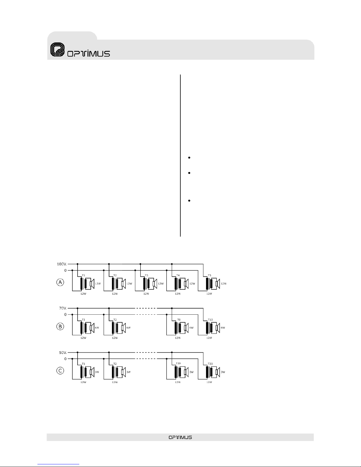
4.8. Loudspeaker line outputs
The loudspeaker line output is effected by means
of a transformer that has low impedance (4-8-16
ohms) and high impedance (50-70-100 V)
outputs.
The connection must be made between terminal
"0" and the terminal corresponding to the
selected impedance or voltage.
When working with the 50, 70 and 100 V lines, it
should be remembered that:
The loudspeakers must be equipped with a
line transformer.
The total connected power will be the sum of
the power absorbed by the loudspeakers and
this must be between 50% below and 20%
above the rated power of the amplifier.
The power absorbed by a loudspeaker with a
transformer is indicated on a 100 V line. If
the amplifier is connected to the 70 V line, it
will absorb half the indicated power, and if it
is connected to the 50 V line, it will absorb a
quarter of this power.
Figure 3
Total power absorbed: 60 W
Power absorbed by each
transformer: 12 W
Total power absorbed: 60 W
Power absorbed by each
transformer: 6 W
Total power absorbed: 60 W
Power absorbed by each
transformer: 3 W
Page 12

UP-67ETH, UP-127ETH,
UP-247ETH, UP-367ETH
Digital power unit
UP-x7ETH version 1.1
12
4.9. Paging security auxiliary
relay
It switches:
a) When an announcement that comes from the
PRIORITY analog input is played.
b) When an announcement that comes from the
EMERGENCY analog input is played.
c) When an announcement configured as
PRIORITY and originating from one of the ETH
inputs is played.
d) When a pre-recorded message from the
Coldfire Flash memory of the amplifier is played.
e) When a pre-recorded message from the Flash
memory of the MP3 circuit of the amplifier is
played.
4.10. USB input for prerecorded messages in MP3 format
This connector allows to access to the amplifier
MP3 Flash memory.
This memory can store files in MP3 format to be
used as pre-recorded messages (see section
5.1).
4.11. Emergency (EMG) volume
Regulates the level of the signal applied to the
emergency input.
4.12. PRE OUT volume
Regulates the level of the PRE OUT output.
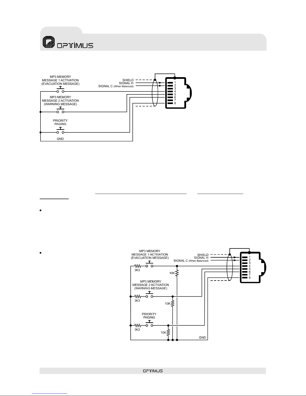
4.13. Emergency input (EMERGENCY IN)
Unbalanced local analog input through an RJ45 connector. Its sensitivity is 0 dBu (775mV).
It has absolute priority over any other signal from the amplifier (ETH inputs, PRIORITY and PROGRAM
inputs, and pre-recorded messages activated through the input/output contacts strip).
There are three types of emergency announcement:
Live voice emergency message: The audio channel of the emergency input is opened when pin
number 6 (speech preference) is connected to pin number 8 (GND) of the connector. Its activation has
priority over any other signal from the amplifier, including the other types of emergency
announcement.
Pre-recorded Evacuation message: This is pre-recorded message number 1 in the MP3 Flash
memory of the amplifier. It is activated when pin number 4 is connected to pin number 8 (GND) of the
connector. Its activation has priority over the activation of the pre-warning message and all other
signals from the amplifier.
Pre-recorded Pre-warning message: This is pre-recorded message number 2 in the MP3 Flash
memory of the amplifier. It is activated when pin number 5 is connected to pin number 8 (GND) of the
connector. Its activation has priority over all signals from the amplifier that are not emergency
signals.
Activation of any of the three types of emergency announcement activates the paging security auxiliary
relay (see section 4.9).
The emergency input has a single volume adjustment situated on the back of the unit (see Figure 2, no.
11) and this affects the volume of live voice messages.
Page 13
UP-67ETH, UP-127ETH,
UP-247ETH, UP-367ETH
Digital power unit
UP-x7ETH version 1.1
13
Pin 1: Audio H (hot)
Pin 2: GND
Pin 3: Not used
Pin 4: Activation of message 1
from the MP3 memory of the
amplifier (evacuation
message).
Pin 5: Activation of message 2
from the MP3 memory of the
amplifier (pre-warning
message).
Pin 6: Priority contact of the
emergency input. Activates
the audio channel of the
emergency input for live voice
messages.
Pin 8: GND
Figure 4. Audio signal
connection, activation of
priority and activation of
emergency input messages 1
and 2.
Figure 5. Connection of the
emergency input with
contact surveillance.
Cat 5 STP cable must be used for the connections.
The Emergency input has Emergency Surveillance (critical path) and Activation Contacts
Surveillance:
Emergency Surveillance (critical path): The device connected to the emergency input must
generate a high frequency signal (17720 Hz, 18000 Hz, 19250 Hz or 20000 Hz). The system performs
a constant check of the high frequency signal, generating an alarm in the event of short circuit,
interruption of continuity or disconnection of this input. The alarm generated is sent through the IP
network towards the control PC or the equipment units prepared to receive these alarms
(DVA-102ETH, FC-600ETH, DC-600ETH). The emergency surveillance function must be configured by
means of the P.A. Manager software (see section 6.7).
Activation Contacts
Surveillance: If the connections
shown in Figure 5 are made, the
system monitors the priority
contact and the two contacts for
activation of pre-recorded
messages from the emergency
input. In the event of short circuit
or disconnection, an alarm is
generated.
Page 14
UP-67ETH, UP-127ETH,
UP-247ETH, UP-367ETH
Digital power unit
UP-x7ETH version 1.1
14
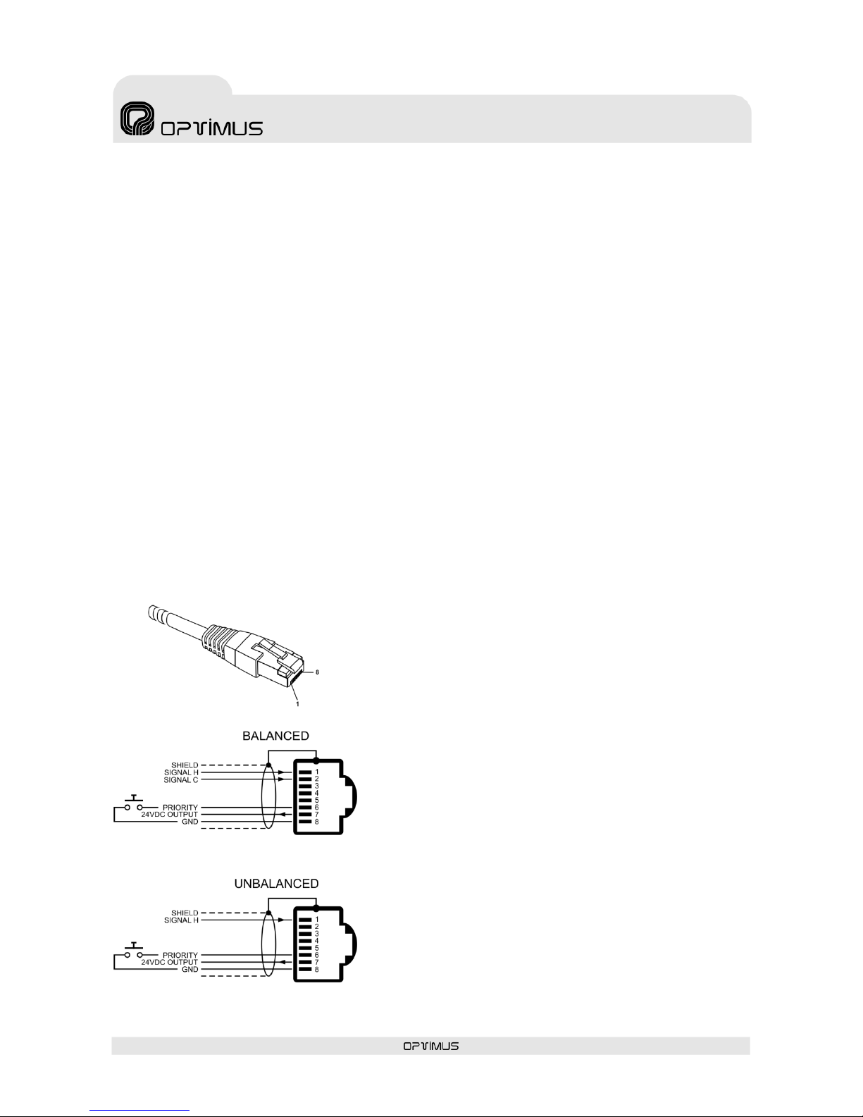
Figure 6. Balanced and unbalanced signal
connection to the priority input
Pin 1: Audio H (hot).
Pin 2: GND
Pin 3: Acknowledge. Allows synchronisation with
external desks (MD-94 family).
Pin 4: Not used
Pin 5: Not used
Pin 6: Priority contact. Priority is activated when pin
number 6 is connected to pin number 8.
Pin 7: Supplies a voltage of 24 V DC that can be used
to power low consumption devices. The maximum
current supplied is 200 mA.
Pin 8: GND
To be able to view these alarms, it is necessary to enable their reception through the P.A. Manager
software. To do this:
1. From the installation screen, open the Options menu and select Alarms Management.
2. On the list of UP-ETH alarms, enable the Emerg. Contact Surveillance, Evac. Contact
Surveillance and Warning Contact Surveillance alarms.
3. Open the File menu and select Save.
4. Open the Optimax menu and select Send configurations to all Optimax equipments.
4.14. Priority input (PRIORITY IN)
Unbalanced analog input with an RJ45 connector and a sensitivity of 0 dBu (775 mV).
It has a priority contact which is activated by connecting pin no. 6 to pin no. 8 of the connector. When
this contact is activated, any signal of a lower priority level is cut off and priority is given to the PRIORITY
IN input, while the paging security auxiliary relay is activated at the same time.
This input is particularly suitable for receiving local announcements (e.g. a microphone with a speech
preference button…).
Cat 5 STP cable must be used for its connection.
Page 15
UP-67ETH, UP-127ETH,
UP-247ETH, UP-367ETH
Digital power unit
UP-x7ETH version 1.1
15
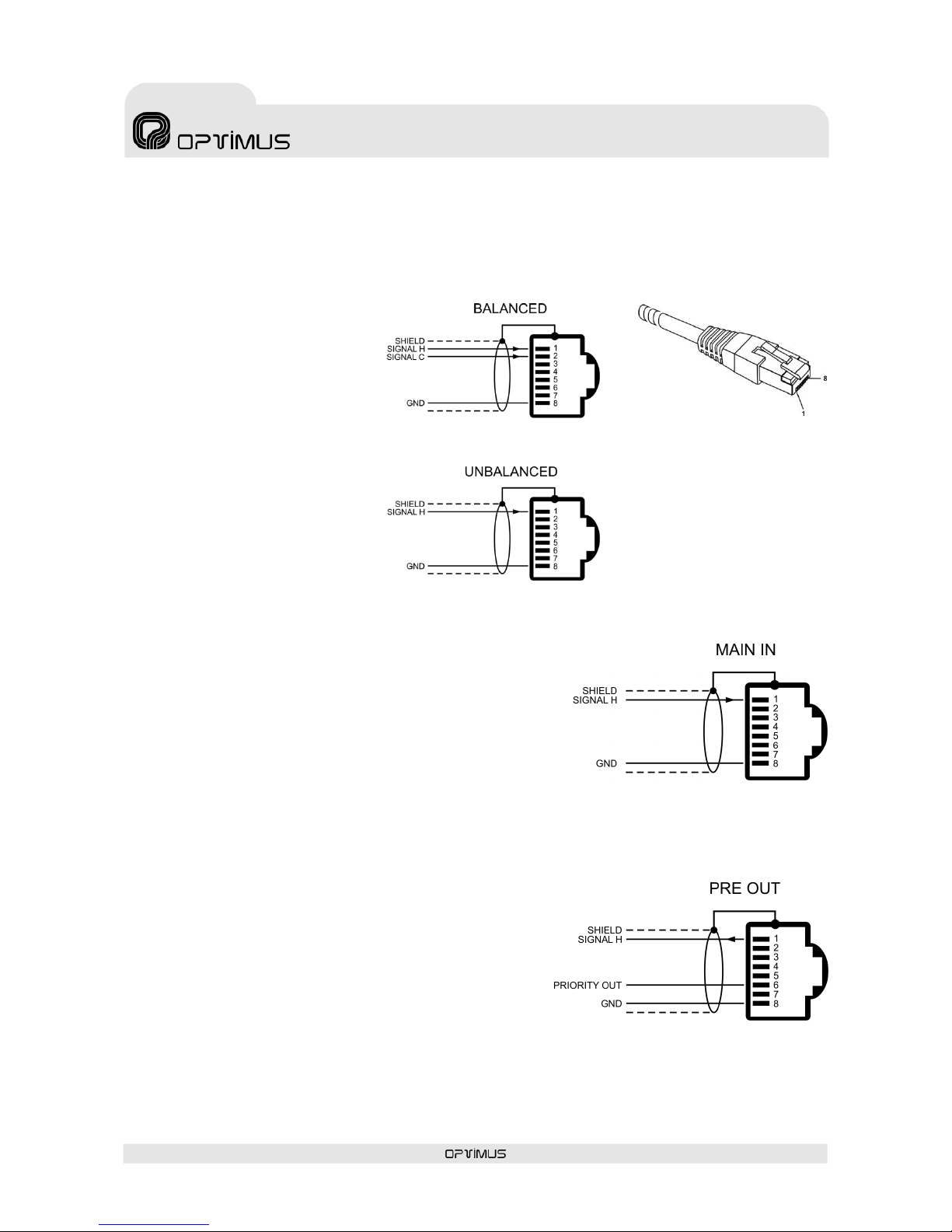
4.15. Program input (PROGRAM IN)
Unbalanced analog input with an
RJ45 connector and a sensitivity
of 0 dBu (775 mV).
It is especially suitable for
receiving a local program signal
(e.g. a CD player, tuner…).
Use Cat 5 STP cable for its
connection.
4.16. MAIN IN
Unbalanced analog input with an RJ45 connector and a
sensitivity of 0 dBu (775 mV).
It is used, together with the PRE OUT output, to insert a unit
(equaliser, anti-larsen...) between the preamp and the power
unit of the amplifier (see Figure 10).
To enable this input, move the LINK switch of the MAIN IN input
to ON.
Use Cat 5 STP cable for its connection and refer to Figure 8.
4.17. PRE OUT
Unbalanced analog output with an RJ45 connector and a
sensitivity of 0 dBu (775 mV).
The audio signal is always present in this output.
It is used, together with the MAIN IN input, to insert a unit
(equaliser, anti-larsen…) between the preamp and the power
unit of the amplifier (see Figure 10), or to send a signal to
other power units (see Figure 11).
It has an output priority contact, which is activated according
to the configuration of the power unit (see section 6.2.2).
Use Cat 5 STP cable for its connection and refer to Figure 9.
Pin 1: Audio H (hot).
Pin 2: GND
Pin 3: Not used
Pin 4: Not used
Pin 5: Not used
Pin 6: Not used
Pin 7: Not used
Pin 8: GND
Figure 7. Balanced and unbalanced signal connection to the program input
Figure 8
Figure 9
Page 16

UP-67ETH, UP-127ETH,
UP-247ETH, UP-367ETH
Digital power unit
UP-x7ETH version 1.1
16
4.18. MAIN IN LINK
Sliding this switch to ON disconnects all the audio signals from the amplifier input, connecting only the
MAIN IN input.
Figure 10
Figure 11
Page 17
UP-67ETH, UP-127ETH,
UP-247ETH, UP-367ETH
Digital power unit
UP-x7ETH version 1.1
17
4.19. RS-485 ADDRESS DIP
switch
This is used to assign a communication address
to the unit, within an RS485 bus. Each unit
connected to an RS-485 bus must have a
different address.
The type of protocol used is CSMA (Carrier Sense
Multiple Access).
For configuration, refer to Table I on the next
page.
4.20. RX and TX indicators
Reception (Rx) and transmission (Tx) indicators
of the RS485 bus.
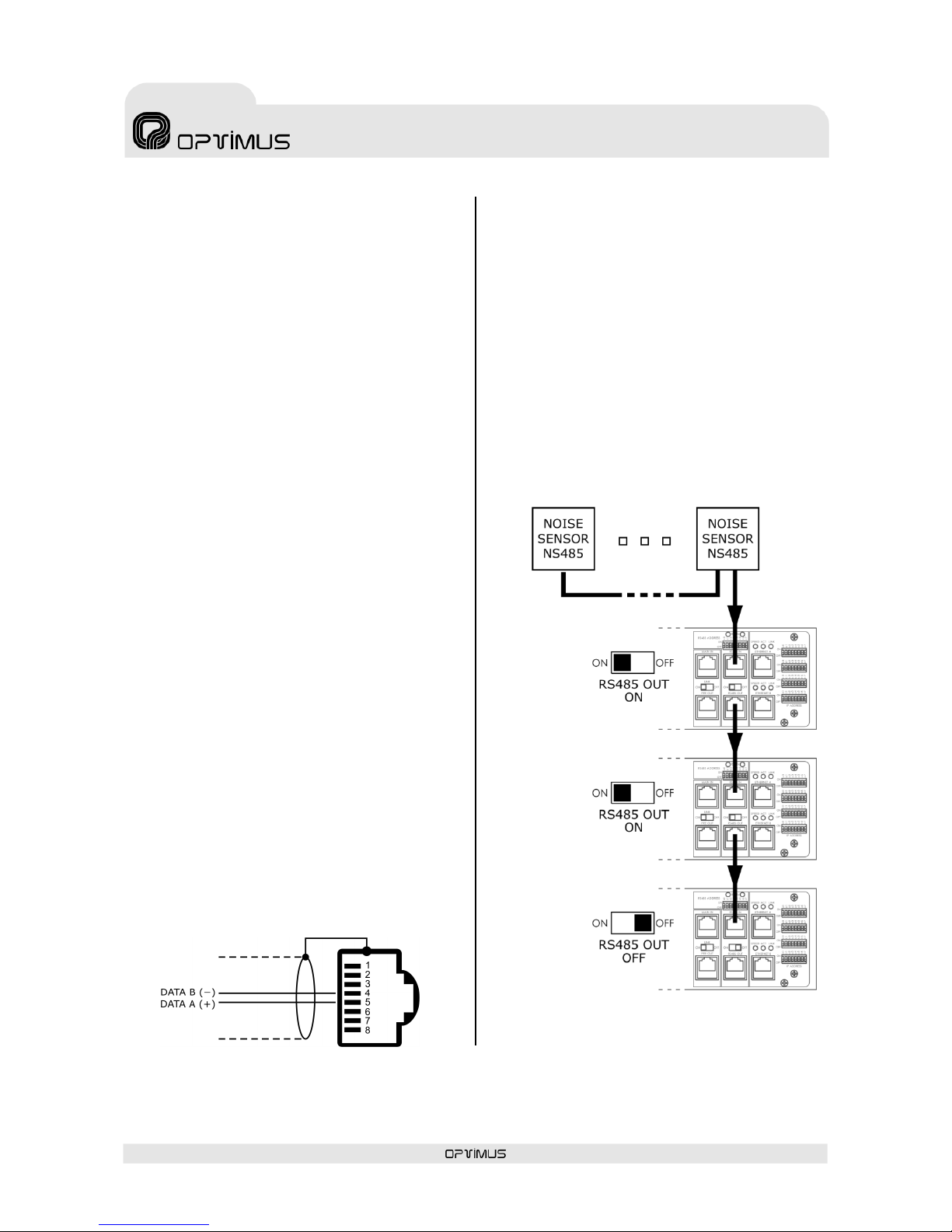
4.21. RS485 IN connector
RJ45 type connector. This is used to connect the
amplifier to an RS485 communication bus.
For its connection, refer to Figure 12.
4.22. RS485 OUT connector
RJ45 type connector. Its purpose is to give
continuity to the RS485 bus and connect other
elements.
If this output is used, the RS-485 ON/OFF switch
must be moved to the ON position.
For its connection, refer to Figure 12.
4.23. RS485 ON/OFF
In the ON position, it enables the RS-485 OUT
connector, and in the OFF position, it loads the
bus with the end of line impedance.
If the amplifier is the first or last element of the
RS-485 bus, the switch must be moved to the
OFF position. If the amplifier is an intermediate
element of the RS-485 bus, the switch must be
moved to the ON position.
Figure 13 shows an example on an RS485 bus
formed by three amplifiers and several NS-485
noise sensors.
Figure 12
Figure 13
Page 18

UP-67ETH, UP-127ETH,
UP-247ETH, UP-367ETH
Digital power unit
UP-x7ETH version 1.1
18
Table I. Configuration of DIP switches.
Page 19

UP-67ETH, UP-127ETH,
UP-247ETH, UP-367ETH
Digital power unit
UP-x7ETH version 1.1
19
N.B.: The IP address can also be set by software. To do
this, refer to section 7. If this action is taken, the IP
ADDRESS DIP switches of the amplifier cease to be
operative.
4.24. ETHERNET A input 10 Mb,
ACT and LINK LED indicators
10 Mb: Indicates the speed of the IP network
connected to the ETHERNET A input. If the LED is
lit, it indicates a speed of 10 Mb. If unlit, it
indicates a network speed of 100 Mb (use of a
transmission speed of 100 Mbps is highly
recommended).
ACT: ACTIVITY indicator. It lights when data is
being sent or received through the ETHERNET A
input.
LINK: When lit, it indicates the connection of the
ETHERNET A input with the HUB or SWITCH.
4.25. ETHERNET B input 10 Mb,
ACT and LINK LED indicators
These serve the same purpose as the ETHERNET
A indicators, applied in this case to the
ETHERNET B input.
4.26. ETHERNET A connector
RJ45 type connector. Used for connection to the
IP network. Cat 5 STP cable must be used for its
connection.
4.27. ETHERNET B connector
RJ45 type connector. Used, in a redundant
network, as a secondary connection to the IP
network. Cat 5 STP cable must be used for its
connection.
If the connection to ETH A fails, the amplifier
automatically switches to this B connection, so
that the PA system continues to operate.
4.28. IP ADDRESS DIP switches
The IP address of the amplifier is configured
through these 4 DIP switches. This address
identifies the amplifier in the network, and so
each unit must have a unique IP address.
An IP address is represented by means of a 32bit binary number. The IP addresses are
expressed as decimal notation numbers: the 32
bits of the address are divided into four octets
(an octet is a group of 8 bits). In the amplifier,
each octet is represented by A0 to A7 for the first
octet, B0 to B7 for the second octet, C0 to C7 for
the third octet, and D0 to D7 for the fourth octet.
In an octet, each bit can have the value 0 (DIP
switch OFF) or 1 (DIP switch ON). In order to
obtain the decimal value of the octet, the decimal
values of each bit that is in the ON position must
be added up (from left to right: 1, 2, 4, 8, 16,
32, 64 and 128).
Figure 14 shows an example in which the IP
address 192.168.100.128 is configured.
Table I shows all the DIP switch combinations
from 0 to 255.
Figure 14
Page 20

UP-67ETH, UP-127ETH,
UP-247ETH, UP-367ETH
Digital power unit
UP-x7ETH version 1.1
20
5. LOCAL PRE-RECORDED MESSAGES
The amplifier has two internal memories in which files can be stored for subsequent use as local prerecorded messages: MP3 Circuit Memory and Coldfire Flash Memory.
5.1. Pre-recorded messages resident in the MP3 circuit memory
5.1.1. Characteristics
Access/Updating of messages
Through the USB connector on the rear panel, by means of a PC
Memory capacity
16 Mb
Maximum number of messages
20
File format
MP3
The messages contained in the MP3 memory are immediately available when the amplifier is switched on,
thereby complying with the standard EN60849.
5.1.2. Transfer of messages to the MP3 memory of the amplifier
The files must be copied to the MP3 memory with a specific name format. Otherwise the messages
cannot be played.
The MP3 files must have the CRC protection activated (the majority of recording programs support this
option). This ensures constant surveillance of the integrity of messages 1 and 2 in the MP3 memory (files
0001… and 0002…). If there were to be any problem in these files, the amplifier sends an alarm message
through the IP connection towards the different units in the installation that have the capacity to receive
it (FC-600ETH, DC-600ETH, DVA-102ETH, UMX-02/0, control computer…).
To transfer the MP3 files to the amplifier, connect the computer that contains the messages to the
amplifier by means of the USB connector on the rear panel of the amplifier. Use the PC browser to copy
the files to the MP3 memory of the amplifier, which will be shown as an additional disk unit. The files
must be copied into the root directory of the unit, and folders should not be used.
Page 21

UP-67ETH, UP-127ETH,
UP-247ETH, UP-367ETH
Digital power unit
UP-x7ETH version 1.1
21
5.1.3. Activation of messages in the MP3 memory of the amplifier
Activation of the MP3 pre-recorded messages from the input/output contacts of the
amplifier.
9 messages can be activated.
Beforehand, it is necessary to configure this function by means of the
P.A. Manager software (SMP-250V2), so that a different message can
be assigned to each of the nine contacts (see section 6.2.3).
For their connection, refer to Figure 15.
Activation through the EMERGENCY IN connector.
This allows messages 1 and 2 to be activated.
To activate them, use contacts 4 and 5 of the RJ45 connector of the
emergency input, as described in Figure 4 in section 4.13.
Activation from the DC-600ETH / FC-600ETH desks.
Through the IP connection of the amplifier.
Activation from the P.A. Manager software.
5.2. Pre-recorded messages resident in the Flash memory of the
Coldfire circuit (WAV)
5.2.1. Characteristics
Access/Updating of messages
Remotely, by means of a PC, through the IP connection
Memory capacity
6 Mb
Maximum number of messages
3 messages (maximum size of 2 Mb/message)
File format
.WAV
Sampling rate: 48000 Hz, 24000 Hz and 12000 Hz (mono)
Sample size: 16 bits
The messages contained in the Coldfire flash memory are not available until a few seconds after the
amplifier has been turned on.
Figure 15
Page 22

UP-67ETH, UP-127ETH,
UP-247ETH, UP-367ETH
Digital power unit
UP-x7ETH version 1.1
22
5.2.2. Transfer of messages to the Coldfire Flash memory
To transfer the WAV files to the flash memory, it is necessary to have a PC connected to the same IP
network as the amplifier and to use the Optimax Flasher application. This application is supplied
together with the P.A. Manager Software. To install it, run the file Optimax Flasher x.x.exe which can
be found in the folder 02_FIRMWARE of the installation CD and follow the instructions of the assistant.
Once the software has been installed, proceed as follows:
N.B.: The file transfer operations shown below are applicable from version 2.6.1 of the
Optimus Flasher software onwards.
1. Start the Optimax
Flasher application.
2. Select the Advanced
tab (1).
3. Enter the IP address of
the unit in the IP Host
field (2).
4. Select UP-ETH from the
Equipment Type dropdown menu (3).
5. In the Update Options
section, tick the box
corresponding to the
message that you wish
to transfer (4) and
indicate the route and
file that you wish to use.
Repeat this operation
for each of the
messages that you wish
to update.
6. Press the button Start
Update Process (5) to
begin to transfer the
files.
7. Press OK when the process has been completed.
8. Exit the application (File > Quit).
5.2.3. Activation of messages in the Coldfire Flash memory of the amplifier
Activation from the input/output contacts of the amplifier.
3 messages can be activated.
Beforehand, it is necessary to configure this function by means of the
P.A. Manager software, so that a message can be assigned to each of
the first three contacts.
For their connection, refer to Figure 16.
Activation from the DC-600ETH / FC-600ETH desks, through the
ETHERNET connection of the amplifier.
Activation from the P.A. Manager Software (see section 8.5).
(2)
(1)
(3)
(5)
(4)
(4)
(4)
Figure 16
Page 23

UP-67ETH, UP-127ETH,
UP-247ETH, UP-367ETH
Digital power unit
UP-x7ETH version 1.1
23
6. INSTALLATION OF AN AMPLIFIER
To install an UP-ETH, proceed as follows:
1. By means of the P.A. Manager software, add the power unit to the installation. Refer to section 6.1.
2. Configure the parameters of the amplifier (General, Audio, I/O Contacts and Temperature Control
tabs). Follow the instructions in section 6.2.
3. Connect the unit to the installation structure. Refer to section 6.3.
4. Configure the IP address and make the connections. Refer to section 6.4.
5. Send configurations to the amplifier. Refer to section 6.5.
6. Configure the noise sensors. Refer to section 6.6.
7. Configure the surveillance of the amplifier. Refer to section 6.7.
If the amplifier is already configured, connect it and it will be operative as soon as switched on.
a) If the installation has a Server PC, the amplifier will download the configuration variations from the
Server PC in the installation.
b) If the installation does not have a Server PC, when switched on, the amplifier will use the
configurations of its local memory.
6.1. Configuration of the amplifier in the installation by means of the
P.A. Manager software
To configure the unit, it is necessary to have a PC connected to the network that has the SCF-01 or SCM01 (P.A. Manager) software.
1. If the software is the SCM-01, start the application, open the Options menu and select Installations
(administrator user level is required). If the software is the SCF-01, start the application.
N.B.: Prior to configuration of the parameters of the amplifier, it is necessary to have configured the
parameters of the installation and the PA areas.
2. From the installation display, click on the PA area to which you wish to add the power unit.
3. Open the menu Add Equipment, and select the power unit model that you wish to add (UP-36xETH,
UP-24xETH, UP-12xETH or UP-6xETH). The equipment configuration screen appears.
4. Refer to section 6.2. Power unit configuration parameters.
Page 24

UP-67ETH, UP-127ETH,
UP-247ETH, UP-367ETH
Digital power unit
UP-x7ETH version 1.1
24
6.2. Power unit configuration parameters
6.2.1. Configuration of the General tab
(1) Name
Enter a name to identify the equipment unit.
Maximum of 50 characters. In the user interface,
this name identifies the zone selection button.
(2) Type
Amplifier model.
(3) Zone Number
The zone number must not be repeated
anywhere in the installation. If the unit is
intended as a backup amplifier, the zone number
must be “0”.
(4) IP Address
IP address of the amplifier. This must coincide
with the configuration of the IP DIP switches of
the amplifier or with the address configured
through the Web connection (see section 7). It
must be a fixed IP address.
(5) Netmask
In installations where this is required. Consult
the network administrator of the installation.
(6) Gateway
In installations where this is required. Consult
the network administrator of the installation.
(7) IP Multicast
Default setting 239.5.5.5. Do not modify this
field unless the installation topology makes it
necessary. All the units with an IP connection in
the installation must have the same IP Multicast
address.
(8) Multicast Port
Default setting 5000. Do not modify this field
unless the installation topology makes it
necessary. All the units with an IP connection in
the installation must have the same Multicast
Port.
(3)
(1)
(2)
(10)
(4)
(12)
(11)
(5)
(6)
(7)
(8)
(9)
Page 25

UP-67ETH, UP-127ETH,
UP-247ETH, UP-367ETH
Digital power unit
UP-x7ETH version 1.1
25
(9) Send “Heart beat” every (n) seconds
Frequency with which the unit sends a heart
beat signal to the multicast group. This signal
informs the other equipment units in the
installation that the system is operating
perfectly.
(10) Keys Blocked
When this option is activated, the volume control
keys on the front of the amplifier are locked.
(11) Local Manager (12) Global Manager
Defines whether the amplifier is to function as a
priority manager of the Optimax system, either
locally at PA Area level or globally for the
installation, and establishes the priority of this
management with respect to other equipment
units (1 = maximum priority). See the Notes on
Local and Global Co-ordinators on the next page.
Information about the multicast configuration on Optimax equipment
It is possible to modify the
multicast configuration of all the
equipment units in the installation
simultaneously. To do so:
1. From the installation screen,
open the Options menu and
select Multicast
Configuration.
2. A window with the
configurations of the
multicast group appears.
Double click on the data item
that you wish to change.
3. Modify the value and click on
Accept.
4. Confirm the change by
clicking on Yes.
5. Close the Multicast configuration window by clicking on Accept.
ATTENTION: The values that are modified from the multicast configuration window affect all the equipment units in the
multicast group of the installation.
Page 26

UP-67ETH, UP-127ETH,
UP-247ETH, UP-367ETH
Digital power unit
UP-x7ETH version 1.1
26
Default base Multicast addresses, ports and configurations
Broadcast address
Broadcast port
Initial configuration download
255.255.255.255
3333
Multicast address
Multicast port
Initial configuration download
239.5.5.5
8001
Multicast address
Multicast port
Others
Control data
239.5.5.5
5000
Heart beat every 10 seconds
Global audio channels
239.1.0.x
6000 + x
8 simultaneous channels
Local audio channels
239.1.PAArea.x
6000 + (PAArea*100) + x
5 simultaneous channels
Valid ranges (according to the IANA Guidelines for IPv4 Multicast Address)
Multicast address
Multicast port
Others
Control data
Between 239.0.0.0 and
239.255.255.255
Between 1025 and 65536
Heart beat between 1 and 65000
seconds.
Global audio channels
Between 239.0.0.0 and
239.255.255.255
Between 1025 and 65536
1-50 simultaneous channels
Local audio channels
Between 239.0.0.0 and
239.255.255.255
Between 1025 and 65536
1-50 simultaneous channels
Notes on Local and Global Co-ordinators
The system requires management of the digital audio channels at all times, so that the data may circulate freely across the network.
This function is performed by two applications: one at a local level, known as LCC, which manages the digital channels at PA Area
level, and another, known as GCC, which manages the digital channels at a global level (between different PA areas and/or servers).
Each PA Area needs at least one LCC process on one of its equipment units.
If there is more than one PA Area in an installation, and announcements have to made or music programs have to be sent between
PA Areas, a minimum of one GCC process is required on an equipment unit in the installation.
If the number of equipment units so permits, it is advisable to have each process available on at least two equipment units. In this
way, the applications continue to work even when a fault in one of the equipment units occurs.
There are specific equipment to run these applications: CC-100ETH, UMX-CC and UMX-ETH (Control). It is recommended that they
are the ones who made the role of coordinator. If these equipment are not present in the installation, it is advisable that the COU02/0ETH, performs the functions of co-ordinator.
The recommended order of priority depending on the model is as follows:
CC-100ETH
UMX-CC
UMX-ETH
(Control)
COU-02/0ETH
SU-114N
SU-214/0N
UP-xETH
(Backup amplifier)
UP-xETH
UMX-ETH
(program
or priority)
DVA-102ETH
DC-600ETH
FC-600ETH
>
> > >
>
Page 27

UP-67ETH, UP-127ETH,
UP-247ETH, UP-367ETH
Digital power unit
UP-x7ETH version 1.1
27
*N.B.:
The Analog Audio and Digital Audio volume controls
(1) to (8) are only operative if the software is P.A.
Manager version SCF-01.
If the software is SCM-01, the modification of these
volumes must be performed from the operator
screen. P.A. Manager SCM-01 also allows the user to
configure a graphic equaliser and a parametric
equaliser for each digital zone. To configure these,
refer to section 8. Operations from the P.A.
Manager Software.
6.2.2. Configuration of the Audio tab
(1) Analog Audio. Volume Program*
Volume of the analog program channel (audio
signal of the PROGRAM INPUT). Values between 0
(volume off) and 32 (maximum volume).
(2) Analog Audio. Volume Priority*
Volume of the analog priority channel (audio
signal of the PRIORITY INPUT). Values between 0
(volume off) and 32 (maximum volume).
(3) Digital Audio. Volume Program*
Volume of the program digital signal. Values
between -20 (volume off) and 0 (maximum
volume).
(4) Digital Audio. Treble Program*
Treble control for the program digital signal.
Values between -20 and +20 (equivalent to ±10
dB).
(5) Digital Audio. Bass Program*
Bass control for the program digital signal.
Values between -20 and +20 (equivalent to ±10
dB).
(6) Digital Audio. Volume Priority*
Volume of the priority digital signal. Values
between -20 (volume off) and 0 (maximum
volume).
(7) Digital Audio. Treble Priority*
Treble control for the priority digital signal.
Values between -20 and +20 (equivalent to ±10
dB).
(8) Digital Audio. Bass Priority*
Bass control for the priority digital signal. Values
between -20 and +20 (equivalent to ±10 dB).
(15)
(2)
(1)
(4)
(3)
(5)
(6)
(7)
(10)
(16)
(13)
(14)
(8)
(11)
(12)
(9)
Page 28

UP-67ETH, UP-127ETH,
UP-247ETH, UP-367ETH
Digital power unit
UP-x7ETH version 1.1
28
(9) MP3 Audio
MP3 message volume control. Values between 0
and 31.
(10) Local Emg. Source
Open the drop-down menu and select the sound
source whose signal is connected to the
EMERGENCY IN input of the amplifier.
(11) Local Priority Source
Open the drop-down menu and select the sound
source whose signal is connected to the
PRIORITY IN input of the amplifier.
(12) Local Program Source
Open the drop-down menu and select the sound
source whose signal is connected to the
PROGRAM IN input of the amplifier.
(13) Program Return
Enabled: The program signal audio continues
once any priority announcement has ended.
Disabled: After an announcement is made, the
program signal audio is cut off until the user
activates the program once again.
(14) Priority Return
Enabled: If during the course of an
announcement another one of a higher priority
arrives, the first one is interrupted, and once the
announcement of higher priority has ended,
broadcast of the first announcement is resumed.
Disabled: If during the course of an
announcement another one of a higher priority
arrives, the first one is interrupted, and even
when the announcement of higher priority comes
to an end, the first announcement is no longer
played.
(15) Program Channel Selection Button
This is used to configure the music program of
the power unit.
When this button is clicked, a list of the program
audio sources available appears. The icon
indicates the music program selected.
This operation can also be performed from the
P.A. Manager software operator screen (see
section 8.4).
(16) PREOUT Contact Activation
This configures the cases in which the priority
contact of the PREOUT output of the amplifier will
be activated. The table below shows in which
situations this contact is activated according to
the configuration.
Enabling…
the priority contact of the PREOUT output is activated…
Local Emergency Message
… when the live voice priority contact of the emergency input of the amplifier is activated
(pin 6 of the RJ45 connector of the EMERGENCY IN input).
Local Priority Message
… when the priority contact of the PRIORITY IN local input of the amplifier is activated.
ETH Message
… when the amplifier receives a digital message with a priority level assigned via IP.
Prerecorded Message (Flash)
… when a pre-recorded message resident in the Coldfire Flash memory of the amplifier
(WAV) is activated.
MP3 Message
… when a pre-recorded message resident in the memory of the MP3 circuit of the amplifier is
activated.
Warning & Evacuation Message
… when messages 1 or 2 of the emergency input of the amplifier are activated (pin 4 or 5 of
the RJ45 connector of the EMERGENCY IN input).
OGG* Message
*Not available on standard amplifiers. Management of pre-recorded messages in OGG
format is only available on ETH amplifiers configured with a specific firmware.
Page 29

UP-67ETH, UP-127ETH,
UP-247ETH, UP-367ETH
Digital power unit
UP-x7ETH version 1.1
29
(5*) On power units that perform backup amplifier functions (configured as Zone number “0”), the
option Same as faulty UP appears. When this option is enabled, the contact will perform the same
function as the function configured for the same contact number of the power unit that is replaced.
6.2.3. Configuration of the I/O Contacts (Input/Output Contacts) tab
Clicking on this tab opens a section in which each of the 9 contacts on the amplifier rear strip can be
configured as input or output contacts.
The contacts configured as Input have the following functionalities:
PC Notification
Activation of Local Message
Local Message Reset
Activation of Alarm System
Activation of Loudspeaker Line measurement with audible frequency
The contacts configured as Output have the following functionalities:
Associated Input
Associated Group
Indication of Loudspeaker Line measurement
To configure them, proceed as follows:
1. Select Input (1) or Output (2) of the contact that you wish to configure.
2. Open the drop-down menu (3) and select the function of the contact.
3. Click on the button Config. (4) to configure the function selected.
(3)
(2)
(1)
(4)
(5*)
Page 30

UP-67ETH, UP-127ETH,
UP-247ETH, UP-367ETH
Digital power unit
UP-x7ETH version 1.1
30
1. Input contact: PC Notification
When the contact is activated, a text message is sent through
the IP connection towards the different units in the installation
that have the capacity to receive it (FC-600ETH, DC-600ETH,
DVA-102ETH, UMX-02/0, control computer…).
(1) Name. Enter a name to identify the contact.
(2) Contact Status. Defines the standby status of the contact
(NO: Contact normally open; NC: Contact normally closed).
Variation in this status will result in PC notification.
(3) Notification. Do not modify the option Alarm
Notification.
(4) Text Message. Enter the text that you wish to be shown
when the contact is activated. Maximum of 50 characters.
2. Input contact: Local message Activation
When the input contact is activated, a prerecorded message from the MP3 memory or the
Flash memory of the amplifier is activated. The
message is played locally.
When this contact is activated, it is also possible
to activate local pre-recorded messages from
other ETH amplifiers via IP.
(1) Name. Enter a name to identify the
contact.
(2) Contact Status. Defines the standby
status of the contact (NO: Contact normally
open; NC: Contact normally closed). Variation
in this status will result in PC notification.
(3) Message Type. The amplifier has two
internal memories in which files can be stored
for subsequent use as local pre-recorded
messages: MP3 Memory and Coldfire Flash
Memory. Select the memory in which the
message is located.
(4) Message. Number of the message that will
be played when the contact is activated.
(5) Priority. Priority level of the message with
respect to the other signals that the power unit
has to reproduce.
(6) Add button. This is used to create a list of
ETH amplifiers which will play their own
prerecorded message locally if this input contact
is activated.
(1)
(2)
(3)
(4)
(1)
(2)
(3)
(4)
(5)
(6)
(7)
(8)
Page 31

UP-67ETH, UP-127ETH,
UP-247ETH, UP-367ETH
Digital power unit
UP-x7ETH version 1.1
31
Proceed as follows:
1. Click on the button Add.
2. Select an amplifier from the drop-down menu.
2. Select the type of message.
3. Select the message number.
4. Select the priority level of the message with respect to the other
signals that the amplifier has to reproduce.
It is possible to add to or modify this configuration by selecting an
element from the list and using the buttons Modify (7) or Delete (8).
The diagram attached
provides an example with
the configuration described
on the previous page.
Activation of contact 2 of
the amplifier in Zone 2
leads to:
Playback of message 1
with priority 1 in Zone 2
Playback of message 2
with priority 3 in Zone 1
Playback of message 1
with priority 2 in Zone 3
3. Input contact: Local Message Reset
Activation of the contact stops the playback of a local
pre-recorded message from the amplifier.
(1) Name. Enter a name to identify the contact.
(2) Contact Status. Defines the standby status of
the contact (NO: Contact normally open; NC: Contact
normally closed). Variation in this status will stop the
message that is being played.
(3) Message Type. Select the memory in which the
message that you wish to stop is located.
(4) Message. Number of the message that will be
stopped when the contact is activated.
(1)
(2)
(3)
(4)
Page 32

UP-67ETH, UP-127ETH,
UP-247ETH, UP-367ETH
Digital power unit
UP-x7ETH version 1.1
32
4. Input contact: Alarm System Activation
When the contact is activated, a message is played a
certain number of times, and then a second message
is played indefinitely.
The contact must remain activated. If it is
deactivated, the process is stopped.
This functionality is employed in alarm and
evacuation systems.
The messages used belong to the Coldfire Flash
memory.
(1) Name. Enter a name to identify the contact.
(2) Contact Status. Defines the standby status of
the contact (NO: Contact normally open; NC: Contact
normally closed).
(3) Coded Message. Enter the number
corresponding to the first of the messages that are to
be played.
(4) Number Repetitions. Number of times that the
first message will be played.
(5) Evacuation Message. Enter the number corresponding to the second of the messages that are to
be played. This message will be played while the input contact remains activated.
5. Input contact: Speaker Line Audible Frequency Measurement
When the input contact is activated, the loudspeaker
line is measured at audible frequency.
First, it is necessary to have configured the line
surveillance.
(1) Name. Enter a name to identify the contact.
(2) Contact status. Defines the standby status of
the contact (NO: Contact normally open; NC: Contact
normally closed).
(1)
(2)
(3)
(4)
(5)
(1)
(2)
Page 33

UP-67ETH, UP-127ETH,
UP-247ETH, UP-367ETH
Digital power unit
UP-x7ETH version 1.1
33
(3)
(1)
(2)
(4)
(3)
(1)
(2)
(4)
4. Output contact: Associated Input
The output contact is activated when an input contact is activated.
(1) Name. Enter a name to identify the contact.
(2) Contact status. Defines the standby status of the contact
(NO: Contact normally open; NC: Contact
normally closed).
(3) Associated input
contact. Input
contacts whose
activation activates the
output contact. Click
on the button Config
(4) and select the
input contacts
required. To make a
multiple selection, hold
the Ctrl. key down.
5. Output contact: Associated Group
This functionality activates the output contact when the message is sent to a group. It is used for the
creation of “subzones” (activation of MC-L line switching modules).
(1) Name. Enter a name to identify the contact.
(2) Contact Status. Defines the standby status of the contact
(NO: Contact normally open; NC: Contact normally closed).
(3) Associated
Group. Groups whose
activation will lead to
the activation of the
output contact.
The zone
corresponding to the
amplifier whose
contact is being
configured must form
part of the group.
Click on the button
Config (4) and select
the groups required.
To make a multiple
selection, hold the
Ctrl. key down.
Page 34

UP-67ETH, UP-127ETH,
UP-247ETH, UP-367ETH
Digital power unit
UP-x7ETH version 1.1
34
6. Output contact: Indication of Loudspeaker Line measurement
The output contact is activated when the amplifier
performs line surveillance.
(1) Name. Enter a name to identify the contact.
(2) Standby Status. Defines the standby status of
the contact.
NO: Contact normally open;
NC: Contact normally closed.
6.2.4. Configuration of the Temperature Control tab
Through this tab the temperatures at which the cooling fans of the power unit are activated and
deactivated can be configured.
(1) Front Fan.
Activation and
deactivation
temperatures of
the front fan of
the amplifiers
UP-367ETH and
UP-247ETH.
(2) Rear Fan.
Activation and
deactivation
temperatures of
the rear fan of
the amplifiers
UP-367ETH, UP247ETH and UP127ETH.
(3) Alarm
Temperature ON. When the set
temperature is
reached, the unit
generates an
alarm via IP and
the FAIL relay is
activated.
(4) Alarm
Temperature OFF. When the
set temperature is reached, the unit stops sending the temperature alarm via IP and deactivates the FAIL
relay.
(5) Average factor for Frontal Sensor. There are two temperature sensors on the amplifier, one at
the front and another at the back. The temperature of the amplifier is obtained from the weighted
average of these sensors. This value indicates the weighting of the front sensor with respect to the rear
sensor.
(1)
(2)
(1)
(2)
(3)
(4)
(5)
(1)
(2)
(3)
(4)
(5)
Page 35

UP-67ETH, UP-127ETH,
UP-247ETH, UP-367ETH
Digital power unit
UP-x7ETH version 1.1
35
6.3. Connecting the equipment in the installation structure
When equipment units are added to the installation, they appear in the structure with their name in red,
preceded by the “disconnection” icon. While their status is shown as disconnected, these equipment units
are not operative.
To connect the equipment, proceed as follows:
1. In the installation structure, right click with the mouse on the
disconnected equipment unit.
2. Click on Connect Equipment. The connection icon appears and
the name of the equipment is shown in green.
6.4. Connection to the installation network
1. Before connecting the amplifier, configure the IP address by means of the DIP switches on the rear
panel of the unit (see section 4.28) or by recording the IP in the Flash memory by means of software
(see section 7).
2. Connect the unit to the IP network.
3. Connect the unit to the power supply.
6.5. Sending configurations to the unit
Before sending configurations to any equipment unit, it is advisable to save the configuration. To do this,
open the File menu and select Save.
1. On the installation tree, right click with the mouse on the name of the unit and select the option Send
Configurations.
2. A progress bar appears. Upon completion, click on OK.
You can exit the Installation screen by opening the File menu and selecting Quit.
The P.A. Manager software will start up automatically.
= Unit disconnected
= Unit connected
Page 36

UP-67ETH, UP-127ETH,
UP-247ETH, UP-367ETH
Digital power unit
UP-x7ETH version 1.1
36
6.6. Configuration of the Automatic Level Control tab
By clicking on this tab, the parameters for the automatic level control of the amplifier in installations with
NS-485 noise sensors can be configured.
If noise sensors are not used, leave the controls on Bypass.
If you have noise sensors, proceed to configure the automatic level control parameters. It is necessary to
have the amplifier connected to the IP network, and the noise sensors must be connected to the amplifier
through the RS485 bus.
1. Press the button Enter Adjust Mode (1).
2. Deactivate Bypass (2).
3. Configure the Measurement interval (3): Interval in time, in seconds, between two consecutive
measurements of the noise level (0 = continuous measurement).
4. Configure the attenuation level of the program channel during measurement (4).
5. Enter the Reverberation Time (5) of the room or zone where measurement is performed.
6. Click on the button Config (6).
(20)
(19)
(18)
(17)
(16)
(14)
(15)
(13)
(6)
(5)
(4)
(3)
(2)
(1)
Page 37

UP-67ETH, UP-127ETH,
UP-247ETH, UP-367ETH
Digital power unit
UP-x7ETH version 1.1
37
10. Once all the sensors have been assigned, click on the button Close (12).
11. Press the button Exit Setting Mode (1).
12. Close the configuration window of the digital amplifier by clicking on the button OK (13).
13. Send configurations to the amplifier by following the instructions in section 6.5.
18. Next, turn to the amplifier and proceed as follows:
a. Connect a pink noise generator to the PRIORITY IN input of the amplifier. Activate the priority
of this input.
b. Using the buttons on the front of the amplifier, increase the priority volume until the desired
maximum paging volume level is obtained in this zone. Once the sensor has been configured, the
volume of the paging channel of the amplifier will never exceed this volume established,
independently of the noise level captured by the sensor.
7. Press Add (7) to assign a noise sensor to the amplifier.
8. Configure the parameters of the
NS485 sensor.
Name (8): Enter a name to identify
the noise sensor.
Address (9): Enter the RS485
address of the noise sensor.
Weighting (10): If several noise
sensors are assigned to an amplifier,
the noise value is obtained by
calculating the weighted average of
the values obtained by each of the
sensors. The Weighting parameter
indicates the weighting of each of
the sensors in the calculation of the
noise value.
9. Press OK (11) (repeat steps 7 to 9
if you wish to assign more than one
sensor to the amplifier).
14. Edit the unit once again and select the Automatic Level Control tab.
15. Press the button Enter Setting Mode (1).
16. Select the Priority tab (14).
17. Deactivate Bypass (15).
(8)
(7)
(9)
(10)
(11)
(12)
Page 38

UP-67ETH, UP-127ETH,
UP-247ETH, UP-367ETH
Digital power unit
UP-x7ETH version 1.1
38
20. From the amplifier once again, and with the pink noise generator connected, decrease the priority
volume by means of the buttons on the front of the amplifier until the desired minimum paging
volume level is obtained in this zone. Once the sensor has been configured, the volume of the
paging channel of the amplifier will never be lower than this volume established, independently of
the noise level captured by the sensor.
N.B.: Once the noise sensors have been configured and the configurations sent, the volume controls on the front of the power
unit are no longer operative.
19. Click on the button Read Value (16) of the Maximum Output Level Adjust. Measurement will
be made, and a maximum output volume will be established for the priority channel of the power
unit. The field Measurement Level (17) reflects this value measured by the sensors expressed in
dB.
It must be taken into account the NS485 sensor does not have the precision of a sound
level meter and therefore the value shown in the measurement level field is
approximate.
21. Click on the button Read Value (18) of the Minimum Output Level Adjust. Measurement will
be made, and a minimum output volume will be established for the priority channel of the power
unit.
22. Enter a noise level increment value (19) for the priority channel. This increment determines how
much the volume of the amplifier increases in accordance with the noise value read by the sensors.
23. If the installation so requires, select the tab Program (20) and repeat steps 18 to 23 for the
program channel.
24. Click on the button Exit Setting Mode (1).
25. Click on the button OK (13).
26. Send configurations to the unit, following the instructions in section 6.5.
Page 39

UP-67ETH, UP-127ETH,
UP-247ETH, UP-367ETH
Digital power unit
UP-x7ETH version 1.1
39
IN INSTALLATIONS WITH LOUDSPEAKER LINE AND EMERGENCY SURVEILLANCE, FOR SURVEILLANCE OF THE LOUDSPEAKER LINE
AT NONAUDIBLE FREQUENCIES, USE THE FREQUENCY WHOSE VALUE IS AS FAR AWAY AS POSSIBLE FROM THE EMERGENCY
SURVEILLANCE FREQUENCY.
6.7. Configuration of the Surveillance tab
By clicking on this tab, the surveillance parameters of the loudspeaker line and of the emergency input of
the amplifier can be configured.
Loudspeaker line surveillance: For this purpose, the DSP of the amplifier injects various frequencies
into the loudspeaker line, which it then collects and analyses in order to detect the status of the line
(open line, short circuit or correct line status).
The frequencies used for this monitoring can be nonaudible (20 kHz or 18 kHz) or audible (4 kHz or
400 Hz).
Constant monitoring (continuous measurement) is achieved through the use of nonaudible frequencies.
Audible frequencies are generally used to confirm the line faults detected during measurement at high
frequencies.
Emergency surveillance: The device connected to the emergency input must generate a high
frequency signal (17720 Hz, 18000 Hz, 19250 Hz or 20000 Hz). The system performs a constant check
of the high frequency signal, generating an alarm in the event of short circuit, interruption of continuity
or disconnection of this input. The alarm generated is sent through the IP network towards the
control PC or the equipment units prepared to receive these alarms (DVA-102ETH, FC-600ETH, DC600ETH).
Once the system is in operation, it is possible to generate surveillance reports, which provide a graphic
representation of the behaviour over time of the loudspeaker lines and the critical path of an installation.
For more information, consult the Optimax installations software manuals.
To configure the
surveillance, select the
Surveillance tab. An
assistant appears which
will guide you through
the process of
configuring the
surveillance. Click on
Next (1).
(1)
Page 40

UP-67ETH, UP-127ETH,
UP-247ETH, UP-367ETH
Digital power unit
UP-x7ETH version 1.1
40
6.7.1. Emergency input surveillance
If emergency input surveillance is not required of the unit, click on Next (1).
If you require emergency input surveillance, tick the check box (2) and select a frequency that you
want detect at Emergency Input of this amplifier (3).
Click on the button Start Adjustment (4).
The sliding controls (5) and (6) allow you to set the margin of variation of any volume that may affect
the emergency input, that is to say, how much the volume of the emergency signal can be varied without
affecting surveillance.
Normally, critical path detection is made in all or nothing mode, and so margins of 90% are
recommended.
Once the setting has been made, click on Next (1).
(1)
(2)
(3)
(4)
(5)
(6)
Page 41

UP-67ETH, UP-127ETH,
UP-247ETH, UP-367ETH
Digital power unit
UP-x7ETH version 1.1
41
6.7.2. Loudspeaker Line surveillance
If loudspeaker line
surveillance is not
required, click on Next
(1).
If loudspeaker line
surveillance is required,
tick the check box (7).
Select an AUDIBLE
frequency for
surveillance (8). Use
the sliding controls (9)
and (10) to set the
precision of line
surveillance detection.
The closer the control is
moved to 1%, the more
accurate detection is. We
recommend a setting of
20% (default value).
Select a NO AUDIBLE
frequency for
surveillance (11). Use
the sliding controls (12)
and (13) to set the
precision of line
surveillance detection.
The closer the control is moved to 1%, the more accurate the detection is. We recommend a setting of
20% (default value).
ATTENTION: Excessive precision can lead to the detection of “false” errors, since the
behaviour of the loudspeaker lines is often affected by environmental factors that are not
related with the Public Address system (noise captured by the loudspeakers, temperature,
humidity, magnetic fields…).
Select the Options tab (14).
Configure whether upon detection of
a line error you wish to stop the
music to perform surveillance of this
line again.
Configure the interval of time
between two consecutive line
surveillance sessions, using
NONAUDIBLE frequencies. Enter a
value between 0 and 1440 minutes
(Select the value “0” for continuous
surveillance; Select Off to deactivate
surveillance at intervals of time).
Then click on Next (1).
(14)
(1)
(12)
(13)
(9)
(10)
(8)
(11)
(7)
Page 42

UP-67ETH, UP-127ETH,
UP-247ETH, UP-367ETH
Digital power unit
UP-x7ETH version 1.1
42
Click on the button Start
Check (15). In this way,
a check is made that
there are no short circuits
between this loudspeaker
line and the loudspeaker
lines of other amplifiers in
the installation.
If the result is not
correct, check the
loudspeaker line and once
the problem has been
resolved, check the line
once again.
If the result is correct
(OK), click on the button
Start Adjustment (16).
Setting of the unit is
commenced.
If the result is OK, click
on Next (1).
A summary of the
settings made appears on
the screen.
Surveillance is now
configured.
Select OK (17) and send
configurations to the unit,
following the instructions
in section 6.5.
(17)
(1)
(15)
(16)
Page 43

UP-67ETH, UP-127ETH,
UP-247ETH, UP-367ETH
Digital power unit
UP-x7ETH version 1.1
43
(18)
(19)
If the result of the setting
is not correct or the
values obtained are too
low (values below 200),
the output level of the
surveillance signal may
be too low. In this case,
a window informing of
the error appears.
Click on No (18) to stop
the setting.
Select Back (19) to
return to the previous
screen.
Select the Options tab
(14) and increase the
level of the detection
signal tone (20) and
(21).
Click on Next (1) and
proceed to set the line
surveillance once again.
(14)
(20)
(21)
(1)
Page 44

UP-67ETH, UP-127ETH,
UP-247ETH, UP-367ETH
Digital power unit
UP-x7ETH version 1.1
44
ATTENTION: Scheduling of loudspeaker line surveillance only functions in installations with a Server PC, since it
is activated by the P.A. Manager software.
6.7.3. Monitoring
The P.A. Manager software offers
the option of monitoring a
particular frequency.
Select the Monitor Frequency
(22) tab.
Select the frequency that you
wish to monitor (23).
Click on the button Start
Monitor (24).
To stop monitoring, click on the
button Stop Monitor.
ATTENTION:
Only the frequencies at which
the unit has been previously
set will be correctly
monitored.
6.7.4. Scheduling of line surveillance
In this section, scheduling can be
created for loudspeaker line
surveillance by indicating the
days and times at which it is
wished to perform surveillance.
Enter a Name (25) to identify
the scheduling.
Select Mode (26): Audible or
Non audible.
Select the days of the week (27)
and the time (28).
Click on the button Add (29).
To delete a scheduled
surveillance session, select it
from the list and click on Delete
(30).
(22)
(23)
(24)
(25)
(26)
(27)
(28)
(29)
(30)
Page 45

UP-67ETH, UP-127ETH,
UP-247ETH, UP-367ETH
Digital power unit
UP-x7ETH version 1.1
45
N.B.: To be able to view the page, it
is necessary to deactivate the proxy
in the configuration of the web
browser.
6.8. Configured parameters edition
If required, the configurations of the amplifier can be edited. Proceed as follows:
1. Open the installations screen of the P.A. Manager Software.
2. In the installation structure, right click with the mouse on the name of the amplifier whose
configuration you wish to edit.
3. Select Edit Equipment.
4. The unit configuration window appears. Edit the parameters as required.
5. Once the parameters have been configured, click on the button OK.
6. Save the configuration by opening the File menu and selecting Save.
7. Send the configurations to the unit (Section 6.5).
7. CHANGE OF THE UNIT IP ADDRESS BY SOFTWARE
It is possible to change the IP configuration of the unit by means of the
IP ADDRESS DIP switches on the back of the amplifier or through the
software.
The software option allows the change to be made remotely, without the
need for access to the amplifier.
To make the change by software, from the operator screen of the P.A.
Manager software right click with the mouse on the zone selection icon
corresponding to the amplifier and select the option Web Connection
(1).
If the PC is remote with respect to the installation, open the Internet browser and enter the IP of the unit
in the address bar (for example: http://10.1.1.20). This IP address is the address configured by means of
the IP ADDRESS DIP switches situated on the back of the amplifier.
In both cases, a web page belonging to the unit will load.
Proceed as follows:
1. Enter the password in the
Administrator Login section (2)
(contact technical staff at Optimus and
they will provide you with this) and click
on the button Login.
(1)
(2)
Page 46

UP-67ETH, UP-127ETH,
UP-247ETH, UP-367ETH
Digital power unit
UP-x7ETH version 1.1
46
ATTENTION
If the IP is activated by software, the functionality of IP address selection by DIP switches will be deactivated.
Once the change has been made, it can be undone by deleting the IP software via the web, or by selecting the address 0.0.0.0
on the DIP switches and restarting the unit.
ATTENTION
Once the IP address of the unit has been changed, it is necessary to modify this in the P.A. Manager software as well (see
section 6.2.1) and send configurations to the unit (see section 6.5).
2. Open the Expert menu (3) and click on the Set
IP address option (4).
3. Write the new IP in the IP Address
field (5) (for example: 10.1.1.100)
and click on Save IP Address (6).
(3)
(4)
(5)
(6)
Page 47

UP-67ETH, UP-127ETH,
UP-247ETH, UP-367ETH
Digital power unit
UP-x7ETH version 1.1
47
(2)
(3)
8. OPERATIONS FROM THE P.A. MANAGER SOFTWARE
Once the installation has been configured, from the Operator screen of the P.A. Manager software it is
possible to modify some parameters corresponding to the digital power unit through the zone selection
button.
8.1. Setting the zone volume
1. Right-click with the mouse on the zone selection button and select the
option Adjust Volumes (1).
2. Move the volume controls to the desired position.
3. Click on OK (2).
8.2. Activation and setting of
the graphic equaliser
1. Right click with the mouse on the zone
selection button and select the option Set
Volume (1).
2. Tick the Graphic Equaliser check box (3).
3. Click on the Graphic EQ tab (4) and
configure the parameters of the equaliser.
4. Click on OK (5).
(1)
(4)
(5)
Page 48

UP-67ETH, UP-127ETH,
UP-247ETH, UP-367ETH
Digital power unit
UP-x7ETH version 1.1
48
(2)
(3)
(1)
(2)
(3)
(4)
(4)
(5)
8.3. Activation and setting of the
parametric equaliser
1. Right click with the
mouse on the zone
selection button and
select the option
Adjust Volumes (1).
2. Tick the Parametric
Equaliser check box
(2).
3. Click on the Parametric EQ tab (3).
4. Uncheck the Bypass check box (4) of the filter
that you wish to configure.
5. Configure the parameters of the equaliser and
click on OK (5).
8.4. Assigning the music program
to the zone
1. Right click with the mouse on the
zone selection button and select the
option Adjust Music Programs
(1).
A table appears in which each of the
rows represents a music program
and each of the columns represents
a zone.
The number of rows and columns depends on the number
of zones and music sources in each installation. Click on
the program/zone intersections to assign the music program to this particular zone.
2. Click on OK (2).
8.5. Playback of a local pre-recorded message
1. Right click with the mouse button on the zone and select Local Message
Playback(1).
2. Configure the parameters of the message:
Message type: The digital amplifier has two internal memories in which files
can be stored for subsequent use as local pre-recorded messages: MP3
circuit Flash Memory and Coldfire Flash Memory.
Message Number: Number of the message.
Message Mode: Priority of the message.
3. Click on the button Play (2) to activate message playback.
To stop the message, click on the button Stop (3).
(1)
(2)
(1)
= music program assigned
Page 49

UP-67ETH, UP-127ETH,
UP-247ETH, UP-367ETH
Digital power unit
UP-x7ETH version 1.1
49
9. SOFTWARE CONFIGURATIONS. DEFAULT VALUES
UP-367ETH
UP-247ETH
UP-127ETH
UP-67ETH
Zone number
Unused low number
IP multicast
239.5.5.5
Multicast port
5000
Heart beat
10 seconds
Local co-ordinator
Deactivated
Global co-ordinator
Deactivated
Keypad lock
Deactivated
Analog audio. Program volume
15 (range from 0 to 32)
Analog audio. Priority volume
15 (range from 0 to 32)
Digital audio. Program volume, bass and
treble
Volume = -10 (range from -20 to 0)
Bass = 0, Treble = 0 (range from –10 to +10)
Digital audio. Priority volume, bass and
treble
Volume = -10 (range from -20 to 0)
Bass = 0, Treble = 0 (range from –10 to +10)
MP3 volume
22 (range from 0 to 31)
Parametric equaliser
Deactivated
Graphic equaliser
Deactivated
Sound sources
None
Program and priority return
Activated
Activation of PREOUT contact
Deactivated
Contact inputs/outputs
Contacts 1 to 9 configured as inputs, disabled.
Activation of front fan
60°
60°
100°
-
Deactivation of front fan
45°
45°
90°
-
Activation of rear fan
100°
100° - -
Deactivation of rear fan
90°
90° - -
Activation of temperature alarm
110°
110°
110°
110°
Deactivation of temperature alarm
105°
105°
105°
105°
Weighting between temperature sensors
(value of the front sensor)
50%
Automatic level control
Deactivated, in BYPASS mode
Line surveillance
Deactivated
Emergency input surveillance
Deactivated
Page 50

UP-67ETH, UP-127ETH,
UP-247ETH, UP-367ETH
Digital power unit
UP-x7ETH version 1.1
50
10. TECHNICAL SPECIFICATIONS
UP-367TH
UP-247ETH
UP-127ETH
UP-67ETH
RMS power output
360 W
240 W
120 W
60 W
IHF power output
482 W
312 W
162 W
82 W
Total harmonic distortion
< 0.65 % (1 kHz)
< 0.5 % (1 kHz)
< 0.5 % (1 kHz)
< 0.5 % (1 kHz)
Bandwidth
50 ~ 18,000 Hz
(- 3 dB)
50 ~ 16,500 Hz
(- 3 dB)
50 ~ 17,000 Hz
(- 3 dB)
50 ~ 17,500 Hz
(- 3 dB)
Power unit signal/noise ratio
> 80 dB
> 83 dB
> 83 dB
> 83 dB
Control preamp signal/noise ratio
> 75 dB
> 75 dB
> 75 dB
> 75 dB
Inputs
1 program (0 dBu), 1 priority (0 dBu), 1 emergency (0 dBu), 2 Ethernet, MAIN IN, RS485
Analog input sensitivity
775 mV (program, priority, emergency and MAIN IN)
Loudspeaker line output
100 V, 70 V, 50 V / 4, 8, 16 ohms
Controls
Front program and priority volume,
rear Emergency and PRE OUT volume
Input/output contacts
9
Mains supply
230 V AC
Battery supply
24 V DC
Off-load consumption
41 VA
34.2 VA
32.5 VA
41 VA
Full load consumption
752 VA
485 VA
278 VA
163 VA
Fan activation
temperature
Front
Configurable
Configurable
Configurable
-
Rear
Configurable
Configurable
-
-
Overheating protection
95 °C
110 °C
110 °C
110 °C
Dimensions (mm)
482.6 (w) x 89 (h) x 368.5 (d)
Rack units
2
Weight
16.7 kg
14.7 kg
11 kg
9.6 kg
Finishes
Iron front panel painted RAL9005, iron cover painted black
Page 51

UP-67ETH, UP-127ETH,
UP-247ETH, UP-367ETH
Digital power unit
UP-x7ETH version 1.1
51
11. NETWORK SPECIFICATIONS
The Optimax PA system supports audio and control data communication through Ethernet and IP
networks. Since it works on levels 3 and 4 of the OSI scale, the Optimax protocol supports
communication through routers (IP protocol) by means of the configurations of the gateways and
subnetwork masks. Thanks to these features, Optimax can work on both LANs and WANs.
Most of the communications in the Optimax systems use multicast. Multicast is an effective means of
providing transit services from one sender to many receivers. It is absolutely essential to exhaustively
and rigorously check the network configuration in order to ensure that the system operates correctly.
The multicast networks include a wide range of protocols, from filter protocols (IGMP, MLD) to routing
protocols (MOSPF, DVMRP, PIM-DM and PIM-SM/SSM).
Optimax incorporates an application-level control (ACK) (level 7 of the OSI scale) of the management
data sent.
1. Default multicast base addresses, ports and configurations
Dirección Broadcast
Puerto Broadcast
Initial configuration download
255.255.255.255
3333
Dirección Multicast
Puerto Multicast
Initial configuration download
239.5.5.5
8001
Multicast address
Multicast port
Others
Control data
239.5.5.5
5000
Heart beat every 10 seconds
Global audio channels
239.1.0.x
6000 + x
8 simultaneous channels
Local audio channels
239.1.PAArea.x
6000 + (PAArea*100) + x
5 simultaneous channels
2. Valid ranges (according to the IANA Guidelines for IPv4 Multicast Address)
Multicast address
Multicast port
Others
Control data
Between 239.0.0.0 and
239.255.255.255
Between 1025 and 65536
Heart beat between 1 and 65000
seconds.
Global audio channels
Between 239.0.0.0 and
239.255.255.255
Between 1025 and 65536
1-50 simultaneous channels
Local audio channels
Between 239.0.0.0 and
239.255.255.255
Between 1025 and 65536
1-50 simultaneous channels
3. Local network (LAN) specifications
- Dedicated VLAN
- Bandwidth: 4 Mb for each audio channel.
- Number of audio channels:
Up to 50 global channels (from the exchange to the satellites)
Up to 50 local channels (internal to the satellite, they do not consume backbone bandwidth)
Page 52

UP-67ETH, UP-127ETH,
UP-247ETH, UP-367ETH
Digital power unit
UP-x7ETH version 1.1
52
4. Switch/router specifications for LAN and
WAN networks
- Protocols:
UDP/ IP multicast for Audio.
UDP/ IP multicast for Control. Security of
reception by means of ACK management
protocol in Application Layer.
- Multicast snooping:
Multicast filtering
IGMP v2
- For large installations:
Multicast routing (Spanning Tree)
Capacity to handle TOS (Type Of Service)
5. Certified hardware
- Large installations:
Nortel: BayStack 470, Ethernet Routing
Switch 3510 and higher
Cisco: 36XX or higher
Alcatel: Level 3 switches
- Medium-sized installations:
NKF: XSNET 1800
Hirschmann: RS30-0802O6O6SDAEHH01.0
- Small installations, with a proprietary
network:
Nortel: BayStack 425
Cisco: 500G and 29600 families
Equitel: N950
6. Network protocol stack
(*) Multicast addresses and reserved ports
Page 53

UP-67ETH, UP-127ETH,
UP-247ETH, UP-367ETH
Digital power unit
UP-x7ETH version 1.1
53
12. SOFTWARE AND FIRMWARE VERSIONS
The functionalities described in this user’s manual are valid for the following software and firmware
versions (or later versions):
UP-x7ETH Firmware
Image (Operating System) 2.4
Coldfire Application 2.6.8
Congestion Control Application 2.6.8
DSP 5.6
Contacts 1.4
LEDs 1.3
MP3 1.2
Master RS485 1.4
P.A. Manager Software
Version 2.6 / Revision 3995.26517
Optimus Flasher Software
Version 2.6.7
13. DOCUMENT VERSION TRACKING
Reference system
Type of Document
Confidentiality
N/A
Optimax
Installation and operation guide
Rev
Date
Modifications Content
Written by:
1.0
December 09
First version, based on UP6ETH_V1.21
R&D Department
1.1
December 10
The following sections are modified:
6.2.1. Configuration of the General tab (table “Default base
Multicast addresses” and table “Valid Ranges”).
11. NETWORK SPECIFICATIONS
R&D Department
Approved By
Function
Date
Ferran Gironès i Puig
R&D Director
07/2010
Page 54

UP-67ETH, UP-127ETH,
UP-247ETH, UP-367ETH
Digital power unit
UP-x7ETH version 1.1
54
14. GUARANTEE
1. GUARANTEE CERTIFICATE
1. OPTIMUS S.A. guarantees that its products are free from material and
manufacturing defects when they are first delivered to the purchaser.
2. In accordance with the conditions outlined here, OPTIMUS S.A.
guarantees its products for two (2) years from the date on which the
purchaser acquires the product. If, within this guarantee period, defects
appear which are not due to factors outlined in section 2, OPTIMUS S.A.
shall replace or repair the unit using equivalent, new or reconstructed
replacement parts, as it deems fit. If replacement parts are applied which
improve the unit, OPTIMUS S.A. reserves the right to charge the client for
the additional cost of these components.
3. No guarantee benefits shall be provided other than those cited here.
4. In order to claim the guarantee rights, it shall be an essential
requirement to present the original purchase invoice or the guarantee
certificate.
2. GUARANTEE PROVISIONS
1. In the event that the product had to be modified or adapted to
comply with local requirements concerning technical specifications or
safety, and if the country in question is not the country for which the
product was originally designed and manufactured, defects are not
considered to be material or manufacturing defects. Furthermore, the
guarantee does not cover the execution of these modifications or
adaptations, regardless of whether or not they have been carried out
correctly.
Nor shall OPTIMUS S.A. be responsible for any costs under this guarantee
for these types of modifications.
2. The guarantee shall not entitle the purchaser to inspection or free
maintenance or repair of the unit, particularly if the defects are due to
inappropriate use. Nor do the guarantee rights cover defects in wearing
parts that become worn as a result of normal wear and tear. Wearing
parts are, in particular, potentiometers, switches/keys, and similar parts.
3. The guarantee does not cover defects in the equipment unit caused
by:
Abuse or incorrect use of the unit for purposes other than those for
which it is intended, in non-compliance with the service and
maintenance instructions specified in the Manual and/or Technical
Instructions for the unit.
Connection or use of the product in a manner that does not
correspond to the technical or safety requirements of the country in
which the unit is used.
Installation in conditions other than those indicated in the Manual
and/or Technical Instructions.
Deficiency or interruptions in the electricity supply or installation
defects which imply use in abnormal conditions.
Damage caused by other equipment units that are connected to the
product.
The use or installation of Software (programmes), interfaces, parts or
supplies not provided and/or not authorised by OPTIMUS S.A.
Failure to use the original packaging for transportation.
Damage caused by force majeure or other causes not attributable to
OPTIMUS S.A.
4. The following elements are not covered by this guarantee:
All plastic surfaces and all parts exposed to outdoor conditions which
have been scratched or damaged as a result of normal or abnormal
use.
Breakages, knocks, damage due to a fall or scratches caused by
moving the unit in any way.
Damage caused by tests, use, maintenance, inst allation or
inappropriate adjustments, or as a result of any alteration or
modification of any kind not carried out by a Service Authorised by
OPTIMUS S.A. in compliance with this guarantee.
Damage to persons or property that might be caused by the improper
use of the equipment, including lack of maintenance.
5. The guarantee shall not be valid whenever the following is observed:
Amendments or corrections made to the details of the guarantee
certificate or purchase invoice.
Failure to produce the original invoice or the absence of a date on
this.
Absence of the serial or batch number on the equipment.
6. In the case of personal computers, the guarantee will not cover the
elimination of computer viruses, the restoration of programmes damaged
by these or the reinstallation of the disk following its deletion.
7. The rights of this guarantee are invalidated if the product has been
repaired or opened by staff unauthorised by OPTIMUS S.A. or by the client
himself.
8. If OPTIMUS S.A. were to establish before the client that the damage
affecting the unit does not entitle a claim to be made under the
guarantee, the costs of checking the equipment incurred by OPTIMUS S.A.
shall be borne by the client.
9. Products not covered by the guarantee shall only be repaired once
payment has been effected by the client. In the event that the guarantee
rights do not apply, OPTIMUS S.A. shall duly inform the client. If, within a
period of 6 weeks from this communication, no written repair order is
received from the client confirming acceptance of the costs, OPTIMUS S.A.
shall return the unit in question to the client. In this case, the transport
and packaging costs shall be invoiced separately and payment shall be
made on delivery. In the event that a repair order is sent by the client,
confirming that he assumes the costs of repair, the transport and
packaging costs shall be invoiced additionally, and also separately.
10. If the equipment needs to be transferred to the Authorised Service
Centre, transportation shall be effected by the responsible party according
to the guarantee, who will also bear the freight and insurance costs.
11. In the event of a defect, OPTIMUS S.A. guarantees that the repair
and/or replacement of parts so that the unit operates correctly will be
made within a period of no more than 30 days. Nevertheless, OPTIMUS
S.A. would like to clarify that the normal period does not exceed 30 days.
12. All parts or products replaced as part of the guarantee services shall
become the property of OPTIMUS S.A.
3. TRANSFER OF GUARANTEE
The guarantee is solely awarded to the original purchaser (principal client)
and is not transferable. With the exception of OPTIMUS S.A., no third
party (dealers, etc.) is authorised to award additional guarantees on
behalf of OPTIMUS S.A.
4. CLAIMS FOR DAMAGE
In the event that OPTIMUS S.A. cannot provide a suitable guarantee
service, the purchaser shall not be entitled to claim any indemnity for
damages arising. The responsibility held by OPTIMUS S.A. is limited in all
cases to the invoicing price of the product.
5. RELATION WITH OTHER GUARANTEE RIGHTS AND NATIONAL
LAW
1. This guarantee does not affect the rights of the purchaser with respect
to the vendor arising from the contract of sale accomplished.
2. These conditions of the guarantee provided by OPTIMUS S.A. are valid
as long as they do not contradict the corresponding national law on
guarantee provisions.
3. OPTIMUS S.A. guarantees that this product complies with the safety
regulations in force in the country.
THIS LIMITED GUARANTEE DECLARATION IS THE EXCLUSIVE GUARANTEE
OFFERED BY OPTIMUS S.A. ALL OTHER EXPLICIT OR IMPLICIT
GUARANTEES ARE EXCLUDED, AND THIS ALSO APPLIES TO GUARANTEES
OF MARKETABILITY AND SUITABILITY FOR A PARTICULAR PURPOSE.
(EXCEPT WHEN THESE GUARANTEES ARE REQUIRED BY AN APPLICABLE
LAW). NO GUARANTEE, EITHER EXPLICIT OR IMPLICIT, SHALL BE
APPLIED ONCE THE GUARANTEE PERIOD HAS EXPIRED
OPTIMUS S.A.
After-Sales Service
C/ Barcelona 101
17003 - GIRONA
Tel. 902 151 96 / 972 203 300
Fax. 972 21 84 13
e-mail:girona@optimus.es 9/44/CE1999/44/CE
 Loading...