

Page 1

UP-67
UP-127
UP-247
UP-367
Nº.
Manual de instrucciones
AMPLIFICADOR
Operating instructions
AMPLIFIER
EspañolEspañol
EnglishEnglish
UP-247
Page 2

Page 3

ÍNDICE
1. INTRODUCCIÓN. . . . . . . . . . . . . . . . . . . . . . . . . . . . . . . . . . . . . . . . . . . . . . . . . . . . . . . . . . . . . . . . . . . . . . . . 4
2. VISTA FRONTAL . . . . . . . . . . . . . . . . . . . . . . . . . . . . . . . . . . . . . . . . . . . . . . . . . . . . . . . . . . . . . . . . . . . . . . . . 4
3. VISTA POSTERIOR. . . . . . . . . . . . . . . . . . . . . . . . . . . . . . . . . . . . . . . . . . . . . . . . . . . . . . . . . . . . . . . . . . . . . . 5
4. EL SISTEMA DE VENTILACIÓN. . . . . . . . . . . . . . . . . . . . . . . . . . . . . . . . . . . . . . . . . . . . . . . . . . . . . . . . . . . . 9
5. DIAGRAMA DE BLOQUES . . . . . . . . . . . . . . . . . . . . . . . . . . . . . . . . . . . . . . . . . . . . . . . . . . . . . . . . . . . . . . . 10
6. CONFIGURACIÓN DE FÁBRICA . . . . . . . . . . . . . . . . . . . . . . . . . . . . . . . . . . . . . . . . . . . . . . . . . . . . . . . . . . 10
7. CARACTERÍSTICAS TÉCNICAS . . . . . . . . . . . . . . . . . . . . . . . . . . . . . . . . . . . . . . . . . . . . . . . . . . . . . . . . . . 11
8. CERTIFICADO DE GARANTÍA. . . . . . . . . . . . . . . . . . . . . . . . . . . . . . . . . . . . . . . . . . . . . . . . . . . . . . . . . . . . 12
Esp
ESPAÑOL
AMPLIFICADORES UP-367, UP-247, UP-127 y UP-67
3
UP-367, UP-247, UP-127 y UP-67 Versión 1.0
Page 4
1. INTRODUCCIÓN
2. VISTA FRONTAL
Los modelos UP-367, UP-247, UP-127 y UP-67 son amplificadores de 360, 240, 120 y 60 Wats R.M.S.
respectivamente.
Indicados para ser utilizados en instalaciones de megafonía, avisos de emergencia, música ambiental y
reproducción de la palabra, destacan por su robustezyfiabilidad.
Cada modelo lleva incorporada una protección contra cortocircuito / sobrecarga en la línea de altavoces así como
una protección térmica para evitar averíasporrecalentamientoexcesivo.
Ocupan dos unidades de altura en armarios Rack de 19".
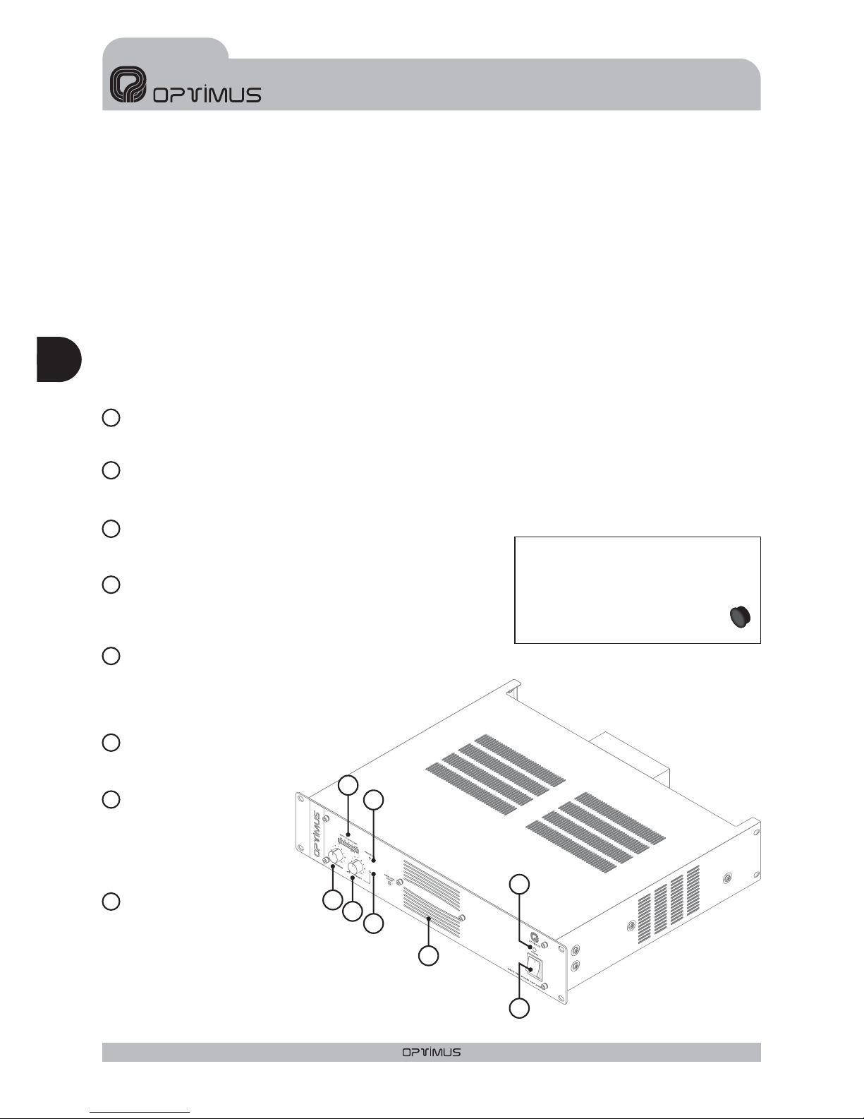
Indica la potencia entregada a la línea. El LED marcado 0 dB refleja el punto donde el amplificador da la
máxima potencia.
Girándolo en el sentido de las agujas del reloj aumentará el volumen del canal de Program. Los botones son
extraíbles
Girándolo en el sentido de las agujas del reloj, aumenta el
volumendelcanaldePrioridad.Losbotonessonextraíbles.
Se ilumina cuando se selecciona el canal de Priority, es decir:
cuando se une el pin nº 6 con el pin nº 8 en el conector RJ45 de la
Entrada de Prioridad.
Se ilumina cuando actúa la Protección, pudiendo ser
debido a una sobrecarga o cortocircuito en la línea
de altavoces o bien por un exceso de la
temperatura interior
Se ilumina cuando el
amplificador está
funcionando tanto en
alimentación de Red
como de Batería.
Conecta y desconecta el
amplificador solo en caso
de que esté alimentado
por la RED de 230 Vcc.Si
funciona alimentado por
batería este interruptor no
actúa.
INDICADOR DE NIVEL
REGULADOR "MASTER" DE ENTRADA DE PROGRAM
REGULADOR "MASTER" DE ENTRADA DE PRIORITY
INDICADOR DE PRIORIDAD
INDICADOR DE PROTECCIÓN
ENTRADADEVENTILACIÓN
No obstruir esta entrada
bajo ningún concepto.
INDICADOR ON/OFF
INTERRUPTORON/OFF
2
1
3
4
5
6
7
8
Una vez ajustado el volumen, puede
protegerse su manipulación extrayendo
los botones y colocando en su lugar los
tapones suministrados en la bolsa de
accesorios.
Figura 1
ESPAÑOL
AMPLIFICADORES UP-367, UP-247, UP-127 y UP-67
4
UP-367, UP-247, UP-127 y UP-67Versión 1.0
Esp
2
1
3
4
5
6
8
7
UP-247
Page 5
Fuse
OUTPUTS
0 50V
FAIL
SURETY
PAGING
70V
100V
16Ω8Ω4
Ω
24V
FAN
POWER
SUPPLY
230V
50/60 Hz
INPUT/OUTPUT CONTACTS
1
234
567
89
PRIORITY
CTRL.INPUT
GND
PRIORITY
INPUT
PRIORITY
OUTPUT
PROGRAM
INPUT
PROGRAM
OUTPUT
ON OFF
POWER AMPLIFIER
240W RMS(312W IHF)
UP-247
Engineered in EU (Spain)
Madein China
OPTIMUS S.A.
PRI-PRORJ CONNECTION
6.PRIORITY
8.
METAL
SHIELD
GND
(WHENBALANCED)
7
8
6
5
3
2
1
DIPSWITCHCONFIGURATION
ON OFF
PRI-PRO
LINK
SHIELD-GND
LINK
7.Priority ctrl. in
6.Audio C
5.Audio H
4.Priority in
8.Priority ctrl. out
3.Priority out
2.Program in
1.Program out
SURVEILLANCE
SURVEILLANCERJ CONNECTION
1.OSC IN
2.NC
3.OSC OUT 1
4.PROTECT
5.OSC OUT 2
6.PRI OUT
7.+24VDC OUTPUT
8.
METAL
SHIELD
GND
24V
FAIL
OUTPUTS
0 50V 70V 100V
4
Ω8Ω16Ω
SURETY PAGING
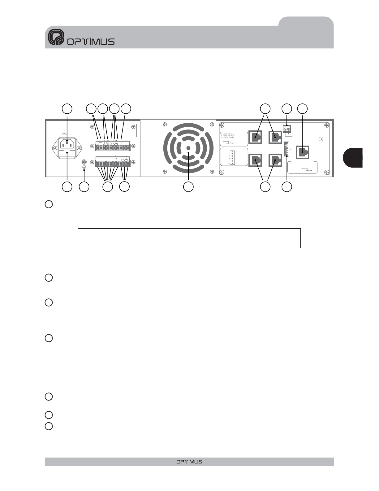
Figura 2
3.VISTAPOSTERIOR
CONEXIÓN A LA REDDE 230V.c.a.
FUSIBLE DE RED
ENTRADAALIMENTACIÓN CON BATERÍA
CONEXIÓN DE LA MASAAL CHASIS
RELÉ FAIL
CONTACTO DE MASA
CONTACTO DE CHASIS
En la placa posterior dispone de una base macho para la alimentación CEE22 que permite conectarlo a la red
mediante el cable suministrado.
El diseño del transformador de alimentación asegura el uso de diferentes tensiones de red. Estos
amplificadores salen de fábrica preparados para funcionar a 230 V.c.a. Bajo pedido se pueden suministrar
preparados para otrosvoltajes
Se encuentra situado en el cajetín inferior de la base de alimentación.También hay un recambio en el mismo
cajetín.
Esta alimentaciónpermite el uso de estos aparatosen instalaciones de seguridad, conectando una batería de
24V.c.c.
El interruptor ON/OFF NO corta laalimentación de la batería.
En toda instalaciónde megafoníaes muyimportante que haya un solo punto deunión entre la masa de señal y
el contacto de tierrade la red.
Si la instalación de megafonía está compuesta por varios aparatos, probablemente tendrán los chasis unidos,
bien mediante el terminal de tierrade la conexióna lared, o bien porque están montados en un armario rack.
Si las masasestán también unidas por los circuitos de señal, es aconsejable quitar el puente entre la masa y el
chasis detodos los aparatos excepto uno.
Se activacuando actúala protección o fallala alimentaciónde red del amplificador.
Atención: Este aparato no puede estar expuesto al agua o a salpicaduras
2
1
3
4
5
6
7
15
5
9
436
128
1
13
14
10
2 11
7
5
UP-367, UP-247, UP-127 y UP-67 Versión 1.0
Esp
ESPAÑOL
AMPLIFICADORES UP-367, UP-247, UP-127 y UP-67
Page 6
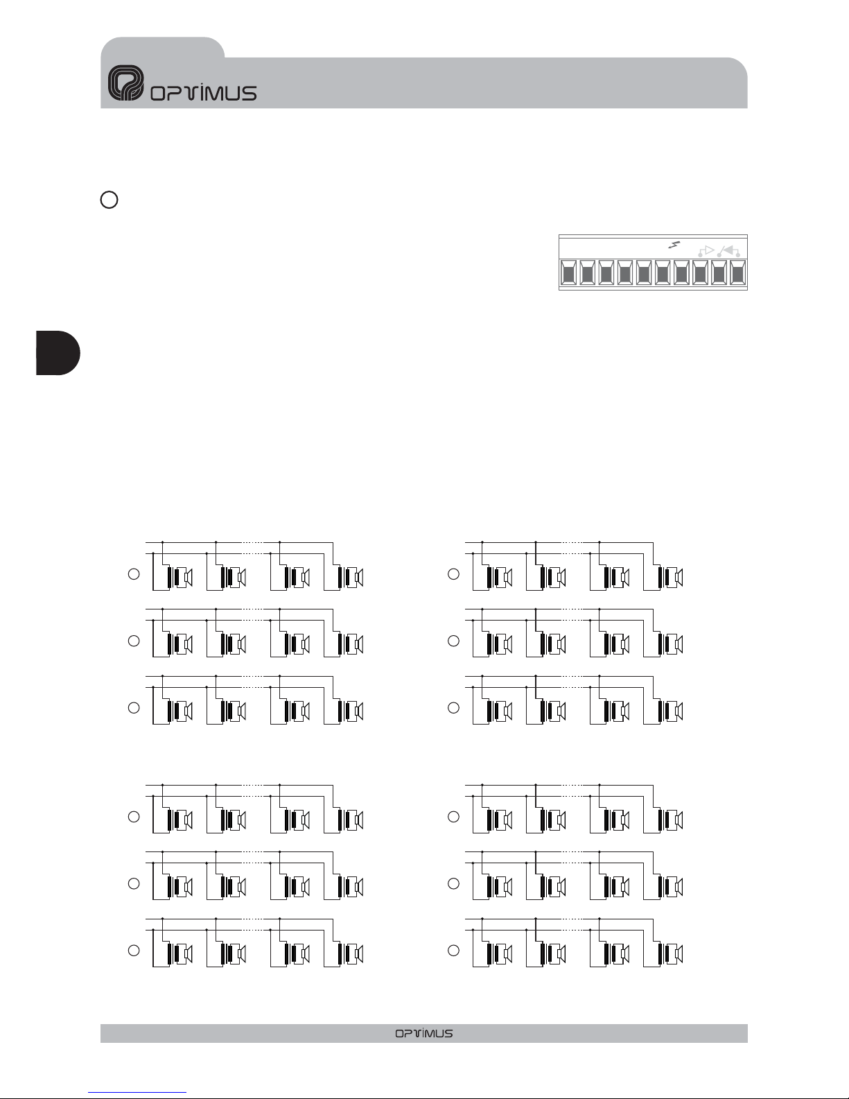
SALIDALÍNEA DE ALTAVOCES
Baja impedancia
Alta impedancia
La salida de la línea de altavoces se efectúa a través de untransformador
que dispone de salidas en baja impedancia (4-8-16Ohms) y en alta
impedancia (50 - 70 -100V).La conexión debe hacerse entre el terminal
“0”y el que corresponda a la impedancia o la tensión adecuada.
Se utilizará una de estas tres salidas cuando los altavoces no tengan transformador de línea y se escogerá de
tal forma que la impedancia de la línea de altavoces sea la misma que la impedancia del contactode salida del
amplificador.
Al trabajar con laslíneas de 50, 70 y 100V. es preciso recordar que:
Los altavocesa conectar deben ir provistos de transformador de línea.
La potencia total conectada será la suma de las potencias absorbidas porlos altavoces y debe estar entre
un 50% por debajoy un 20% por encima de la potencia nominal del amplificador.
La potencia absorbida por un altavoz con transformador está indicada en los terminales del mismo. Esta
potencia es en línea de 100V. Si se conecta el transformador a la línea de 70V, absorberá la mitad de la
potencia indicada y si se conecta a la línea de 50V. absorberá la cuarta parte. Un transformador de 30 W
absorberá 15W si se conecta a la línea de 70V y 7,5 W sise conecta a la línea de 50V.
OUTPUTS
0 50V 70V 100V
4
Ω8Ω16Ω
SURETY PAGING
8
Figura 3
0
0
0
0
0
0
0
0
0
0
0
0
C
C
C
C
B
B
B
B
50V.
50V.
50V.
50V.
70V.
70V.
70V.
70V.
A
A
A
A
100V.
100V.
100V.
100V.
A. Potencia total absorbida 60W. Potencia absorbida por cada transformador de 10W= 10W
B. Potencia total absorbida 60W. Potencia absorbida por cada transformador de 10W= 5W
C. Potencia total absorbida 60W. Potencia absorbida por cada transformador de 10W= 2,5W
A. Potencia total absorbida 240W. Potencia absorbida por cada transformador de 40W= 40W
B. Potencia total absorbida 240W. Potencia absorbida por cada transformador de 40W= 20W
C. Potencia total absorbida 240W. Potencia absorbida por cada transformador de 40W= 10W
A. Potencia total absorbida 120W. Potencia absorbida por cada transformador de 20W= 20W
B. Potencia total absorbida 120W. Potencia absorbida por cada transformador de 20W= 10W
C. Potencia total absorbida120W. Potencia absorbida por cada transformador de 20W= 5W
A. Potencia total absorbida 360W. Potencia absorbida por cada transformador de 60W= 60W
B. Potencia total absorbida 360W. Potencia absorbida por cada transformador de 60W= 30W
C. Potencia total absorbida 360W. Potencia absorbida por cada transformador de 60W= 15W
10W
40W
20W
60W
10W
40W
20W
60W
10W
40W
20W
60W
T1
T1
T1
T1
T1
T1
T1
T1
T1
T1
T1
T1
10W
40W
20W
60W
2.5W
10W
5W
15W
5W
20W
10W
30W
10W
40W
20W
60W
10W
40W
20W
60W
10W
40W
20W
60W
10W
40W
20W
60W
2.5W
10W
5W
15W
5W
20W
10W
30W
UP-67
UP-247
UP-127
UP-367
T2
T2
T2
T2
T2
T2
T2
T2
T2
T2
T2
T2
10W
40W
20W
60W
10W
40W
20W
60W
10W
40W
20W
60W
T23
T23
T23
T23
T11
T11
T11
T11
T5
T5
T5
T5
10W
40W
20W
60W
2.5W
10W
5W
15W
5W
20W
10W
30W
2.5W
10W
5W
15W
5W
20W
10W
30W
10W
40W
20W
60W
10W
40W
20W
60W
10W
40W
20W
60W
10W
40W
20W
60W
T24
T24
T24
T24
T12
T12
T12
T12
T6
T6
T6
T6
ESPAÑOL
AMPLIFICADORES UP-367, UP-247, UP-127 y UP-67
Esp
6
UP-367, UP-247, UP-127 y UP-67Versión 1.0
Page 7
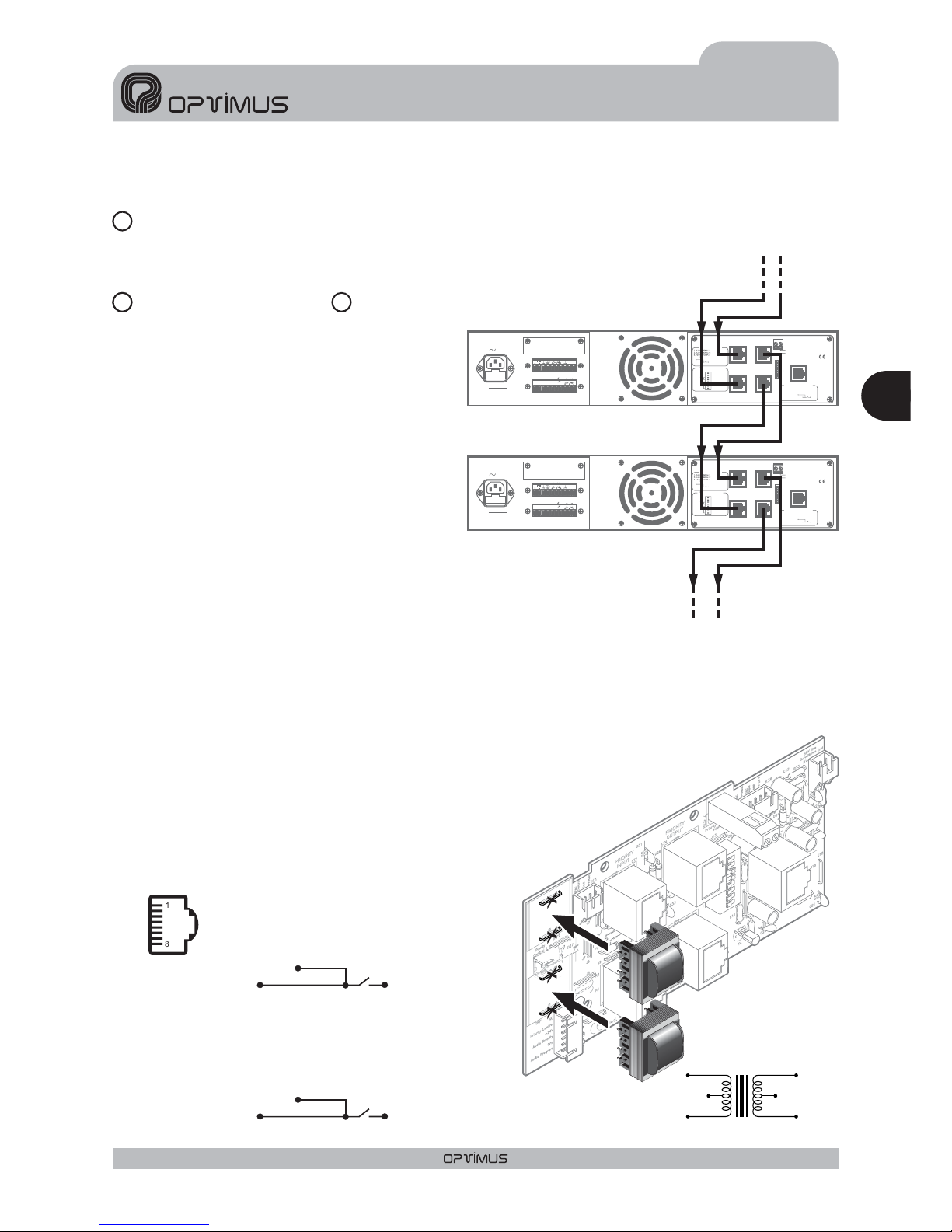
RELÉ AUXILIARDE SEGURIDAD DE AVISOS
CANAL DE PRIORIDAD y CANAL DE
PROGRAMA.
Conmuta cuando seactiva el contactode prioridad delcanal PRIORITY.
Los dos canales de entrada (PROGRAM y
PRIORITY) utilizan 4conectores deltipo RJ45
conectados en paralelo 2 a 2. De este modo,
pueden proporcionar señal a otras etapas de
potencia (verfigura 4).
Para su conexión (ver figura 5) debe utilizarse
cable STP de Cat 5.La principal característica
de este tipo de cable es su muy baja
impedancia, de manera que permite una
respuesta frecuencial excepcionalmente
plana incluso para largas distancias,
cumpliendo evidentemente con las
prestaciones de CMRR y "Crosstalk"
requeridas para audio analógico.
Las entradas de señal son no balanceadas y
tienen una sensibilidad de0 dBu (775mV).
El pin nº 3 proporciona una tensión de 24Vcc que puede utilizarse para alimentar dispositivos de bajoconsumo.
La corriente máxima suministrada es de 200 mA.en cadacanal.
En el canal de PRIORITY, al unir el pin nº 6 con el pin nº 8 se activa el sistema de prioridad, y se activa el relé
auxiliar de seguridad de avisos (ver figura 2, número 9). A través del pin número 6 del conector PRIORITY
OUTPUT, puede transmitirse elcontrol de prioridad a otras etapas de potencia, siempre
en función de la posición de los dipswitchs 7y8(Verpunto 12 del apartado 3. VISTA
POSTERIOR )
Opcionalmente se puede acoplar a estas entradas un transformador
simetrizador (T700) cortando los puentes J1 y J2 para la entrada de
programa, y J3 y J4para la entrada de prioridad, conectando los
transformadores como indicala figura 6.
Fuse
OUTPUTS
050V
FAIL
SURETY
PAGING
70V
100V
16Ω8Ω4
Ω
24V
FAN
POWER
SUPPLY
230V
50/60 Hz
INPUT/OUTPUTCONTACTS
1
234
567
89
PRIORITY
CTRL.INPUT
GND
PRIORITY
INPUT
PRIORITY
OUTPUT
PROGRAM
INPUT
PROGRAM
OUTPUT
ON OFF
POWERAMPLIFIER
240WRMS (312WIHF)
UP-247
Engineered inEU (Spain)
MadeinChina
OPTIMUS S.A.
PRI-PRORJCONNECTION
6.PRIORITY
8.
METAL
SHIELD
GND
(WHENBALANCED)
7
8
6
5
3
2
1
DIPSWITCHCONFIGURATION
ON OFF
PRI-PRO
LINK
SHIELD-GND
LINK
7.Priorityctrl. in
6.AudioC
5.AudioH
4.Priorityin
8.Priorityctrl. out
3.Priorityout
2.Programin
1.Programout
SURVEILLANCE
SURVEILLANCERJCONNECTION
1.OSCIN
2.NC
3.OSCOUT 1
4.PROTECT
5.OSCOUT 2
6.PRIOUT
7.+24VDCOUTPUT
8.
METAL
SHIELD
GND
24V
FAIL
OUTPUTS
0 50V70V 100V
4
Ω8Ω16Ω
SURETYPAGING
Pin number 1: SIGNAL H
Pin number 2: SIGNAL C (if the input is balanced)
Pin number 3: +24VDC
Pin number 6: PRIORITY contact
Pin number 8:
Shield
Pin number 1: SIGNAL H
Pin number 2: SIGNAL C (if the input is balanced)
Pin number 3: +24VDC
Pin number 8:
Shield
PRIORITY CHANNEL CONNECTION
PROGRAM CHANNEL CONNECTION
GND
GND
1
8
Figura 6
Figura 5
N.C. N.C.
600 Ohm 600 Ohm
T-700
9
10
11
Figura 4
PRIORITY CHANNEL
INPUT TRANSFORMER
J4
J3
J2
J1
PROGRAM CHANNEL
INPUT TRANSFORMER
7
UP-367, UP-247, UP-127 y UP-67 Versión 1.0
Esp
ESPAÑOL
AMPLIFICADORES UP-367, UP-247, UP-127 y UP-67
Page 8

Fuse
OUTPUTS
050V
FAIL
SURETY
PAGING
70V
100V
16Ω8Ω4
Ω
24V
FAN
POWER
SUPPLY
230V
50/60 Hz
INPUT/OUTPUTCONTACTS
1
234
567
89
PRIORITY
CTRL.INPUT
GND
PRIORITY
INPUT
PRIORITY
OUTPUT
PROGRAM
INPUT
PROGRAM
OUTPUT
ON OFF
POWERAMPLIFIER
240WRMS (312WIHF)
UP-247
Engineered inEU (Spain)
MadeinChina
OPTIMUS S.A.
PRI-PRORJCONNECTION
6.PRIORITY
8.
METAL
SHIELD
GND
(WHENBALANCED)
7
8
6
5
3
2
1
DIPSWITCHCONFIGURATION
ON OFF
PRI-PRO
LINK
SHIELD-GND
LINK
7.Priorityctrl. in
6.AudioC
5.AudioH
4.Priorityin
8.Priorityctrl. out
3.Priorityout
2.Programin
1.Programout
SURVEILLANCE
SURVEILLANCERJCONNECTION
1.OSCIN
2.NC
3.OSCOUT 1
4.PROTECT
5.OSCOUT 2
6.PRIOUT
7.+24VDCOUTPUT
8.
METAL
SHIELD
GND
24V
FAIL
OUTPUTS
0 50V70V 100V
4
Ω8Ω16Ω
SURETYPAGING
DIPSWITCH DE CONFIGURACIÓN
PRIORITY CONTROL OUT (dipswitch núm. 8)
PRIORITY CONTROL IN (dipswitch núm. 7)
PRI-PRO LINK (dipswitchs núm. 5 y 6)
SHIELD - GND LINK(dipswitchs núm.1,2,3 y 4)
REGLETA PRIORITY CONTROL
En posición OFF, deshabilita el contacto de
prioridad del conector RJ PRIORITY OUTPUT.
En posición OFF, deshabilita el contacto de
prioridad del conector RJ PRIORITY INPUT.
Estos dosdipswitchs unen internamente la señal
de audioHylaseñal de audio C (cuando la
entrada es balanceada ) presentes en la salida
de prioridad (PRIORITY OUTPUT) con la
entrada de programa (PROGRAM INPUT).
Normalmente están enposición OFF (señales de
audio separadas). Para unirlas debe situarse el
dipswitchcorrespondiente enON.
Estos 4 dipswitchs permiten separar la pantalla
del cable de la masa interna del aparato para
cada uno delos conectores RJ-45. Normalmente
están en posición ON (pantalla y masa del
aparato unidas).Para separarlas debe situarse el
dipswitchcorrespondiente enOFF.
Estos contactos permiten
la activación de la
prioridad, facilitando el
cableado de la
instalación.
El diagrama de bloques
de la figura 8 muestra un
ejemplo de instalación
típica.
12
13
OUTPUT - INPUT DIAGRAM
Figura 6
Figura 7
Figura 8
zone 1A
zone 1B
zone 2
zone 3
zone 4
zone 5
UP-127
PM-612/0
MIC
ZONES SELECTOR
C610PAL
UP-127
UP-127
UP-127
UP-127
UP-127
Priority input
RJ connector
Priority input
RJ connector
Priority input
RJ connector
Priority input
RJ connector
Priority input
RJ connector
Priority input
RJ connector
Priority control
input contact
Priority control
input contact
Priority control
input contact
Priority control
input contact
Priority control
input contact
Priority control
input contact
Priority output
RJ connector
Priority output
RJ connector
Priority output
RJ connector
Priority output
RJ connector
Priority output
RJ connector
8 pins RJ45
connectors
Priority
PRI-PRO LINK
SHIELD-GND
LINK
ON OFF
Zone 2, 3, 4 and 5 UP-127 configuration
PRI-PRO LINK
SHIELD-GND
LINK
ON OFF
Zone 1B configurationUP-127
PRI-PRO LINK
SHIELD-GND
LINK
ON OFF
Zone 1A configurationUP-127
ESPAÑOL
AMPLIFICADORES UP-367, UP-247, UP-127 y UP-67
Esp
8
UP-367, UP-247, UP-127 y UP-67Versión 1.0
To power unit
AUDIO H
PRIORITY CTRL.
PRIORITY
CONTROL INPUT
GND
PRIORITY
INPUT
PROGRAM
INPUT
SHLD
SHLD
AUDIO H
SW 7 SW 8
SW 4 SW 3
SW 5
SW 2
SW 1
SW 6
AUDIO C
AUDIO C
PROGRAM
OUTPUT
SHLD
AUDIO H
AUDIO C
AUDIO H
PRIORITY CTRL.
PRIORITY
OUTPUT
SHLD
AUDIO C
Page 9

CONECTORSURVEILLANCE
SALIDADEVENTILACIÓN
No obstruir esta salida bajo ningún
concepto.
UP-367 y UP-247
UP-127
Se utiliza para interconectar el amplificador con
la carta supervisora de líneas, cuando sea
requerimiento de la instalación.
Para la conexión utilice conectores RJ45 con
carcasa metálica (ver figura 9).
Equipada con un ventilador frontal y
uno posterior. El frontal se activa si
la temperatura interna alcanza los
65º. El posterior se activa cuando la
temperatura interior del
amplificador alcanza los 100ºC.
Esto sólo debe ocurrir en
situaciones extremas ya que en
condiciones normales el equipo
está dimensionado para no
necesitar la activación del
ventiladorposterior.
Si la temperatura interna del
aparato superase los 110ºC se
activaríala proteccióndel aparato.
Equipada con un ventilador frontal.
Se activa cuando la temperatura
interior alcanza los 100ºC.Esto sólo
debe ocurrir en situaciones
extremas ya que en condiciones
normales el equipo está
dimensionado para no necesitar la
activacióndel ventilador.
Si la temperatura interna del
aparato superase los 110ºC se
activaríala proteccióndel aparato.
Para sustituir los ventiladores en
caso de avería, siga las figuras 10 y
11.
4. EL SISTEMA DE VENTILACIÓN
14
Pin number 1: OSCILLATION INPUT
: OSCILLATION OUTPUT 1
: PROTECTION OUTPUT
: OSCILLATION OUTPUT 2
Pin number 6: PRIORITY OUTPUT
Pin number 7: +24VDC OUTPUT
8:
Shield
Pin number 3
Pin number 4
Pin number 5
Pin number
GND
1
8
1
8
JP2
(puente interno)
15
Figura 10
Figura 9
Figura 11
9
UP-367, UP-247, UP-127 y UP-67 Versión 1.0
Esp
ESPAÑOL
AMPLIFICADORES UP-367, UP-247, UP-127 y UP-67
O
N
O
F
F
S
U
R
V
E
IL
L
A
N
C
E
R
J
45
C
O
N
N
E
C
TIO
N
7
8
6
5
2
3
1
1
.
O
S
C
IN
2
.
N
C
3
.
O
S
C
O
U
T
1
4
.
P
R
O
T
E
C
T
5
.
O
S
C
O
U
T
2
6
.
P
R
I
O
U
T
7
.
+
2
4
V
D
C
O
U
T
P
U
T
8
.
M
E
T
A
L
S
H
IE
L
D
G
N
D
D
IP
S
W
IT
C
H
C
O
N
F
IG
U
RA
TIO
N
O
N
O
F
F
8.
P
riority
c
trl.
o
ut
7.
P
riority
c
trl.
i
n
6.
A
udio
C
5.
A
udio
H
4.
P
riority
I
n
3.
P
riority
o
ut
2.
P
rogram
i
n
1.
P
rogram
o
ut
PRI-PRO
LINK
SHIELD-GND
LINK
1
.
A
U
D
IO
S
IG
N
A
L
H
2
.
A
U
D
IO
S
IG
N
A
L
C
(
W
H
E
N
B
A
L
A
N
C
E
D
)
3
.
+
2
4
V
D
C
O
U
T
P
U
T
6
.
P
R
I
O
R
I
T
Y
8
.
M
E
T
A
L
S
H
IE
L
D
G
N
D
PR
IO
R
IT
Y
&
P
R
O
G
R
A
M
R
J
4
5
C
O
N
N
E
C
TIO
N
SURVEILLANCE
PRIORITY
INPUT
PRIORITY
OUTPUT
PROGRAM
INPUT
PROGRAM
OUTPUT
PRIORITY
CTRL.
I
NPUT
GND
OPTIMUS
S
.A.
UP-247
POWER
A
MPLIFIER
240W
R
MS
(
312W
I
HF)
Engineering&Q.A.
From
EU(Spain)
MadeinChina
UP-247
Page 10

0
50V
70V
100V
4
Ω
8
Ω
16
Ω
SPEAKERS
LINE
OUTPUT
POWER
STAGE
PRIORITY
CONTROL
INPUT
MASTER
PRIORITY
MASTER
PROGRAM
PRI-PRO
LINK
PROGRAM
PRIORITY
PROTECTION
PRIORITY OUTPUT
PRIORITY INPUT
PROGRAM OUTPUT
PROGRAM INPUT
SURETY
PAGING
FAI L
SURVEILLANCE
Priority & Control Signal
Audio
5. DIAGRAMA DE BLOQUES
6. CONFIGURACIÓN DE FÁBRICA
Por defecto, la configuración de fábrica de las etapas de potencia es la
siguiente:
Contacto de prioridad del RJ45 del conector PRIORITY OUTPUT: ON
Contacto de prioridad del RJ45 del conector PRIORITY INPUT: ON
Unión de la señal de los canales PRIORITY y PROGRAM: OFF
Unión de la pantalla del cable y el conector hacia la massa del
amplificador: ON
ON OFF
PRI-PRO LINKPRI-PRO LINK
SHIELD-GND
LINK
SHIELD-GND
LINK
7 -Priority ctrl. in7 - Priority ctrl.in
8 -Priority ctrl. out8 - Priority ctrl.out
3 -Priority out3 - Priority out
DIPSWITCH CONFIGURATION
Otras configuraciones
JP1 (puente interno) = OFF
JP2 (puente interno) = ON
Surveillance Shield - Ground Link
ESPAÑOL
AMPLIFICADORES UP-367, UP-247, UP-127 y UP-67
Esp
10
UP-367, UP-247, UP-127 y UP-67Versión 1.0
Page 11

7. CARACTERÍSTICAS TÉCNICAS
Potencia de salida R.M.S.
Potencia de salida I.H.F.
Distorsión armónica total
Ancho de banda
Relación señal/ruido
Entradas
Sensibilidad entradas
Salida línea de altavoces
Controles
Alimentación Red
Alimentación Batería
Consumo vacío
Consumo plena carga
Dimensiones (mm)
Protección sobrecalentamiento
Temperatura de activación
del ventilador
Unidades de rack
Peso
Acabados
120 W60 W
UP-127UP-67
240 W
UP-247
360 W
482 W
UP-367
162 W82 W 312 W
< 0,5 % (1 kHz)< 0,5 % (1 kHz) < 0,5 % (1 kHz) < 0,65 % (1 kHz)
50 ~ 18.000 Hz (±3 dB)
1 programa (0 dBu), 1 prioridad (0 dBu)
775 mV (programa y prioridad)
100 V, 70 V, 50V / 4, 8, 16 ohms
Volumen de programa y de prioridad
230 V.c.a.
7,5 VA16 VA 9,2 VA 16 VA
253 VA138 VA
-
460 VA 736 VA
482,6 (w) x 88,8 (h) x 368,5 (d)
Placa frontal en hierro pintada negra. Tapa en hierro pintada negra.
> 80 dB
24 V.c.c.
110º C95º C
Ventilador frontal:100º C*
Ventilador frontal: 65º C
Ventilador posterior: 100º C*
Ventilador frontal: 65º C
Ventilador posterior: 100º C*
2
10 kg8,6 kg 13,6 kg 15,7 kg
(*) En condiciones normales el equipo está dimensionado
para no necesitar la activación del ventilador.
11
UP-367, UP-247, UP-127 y UP-67 Versión 1.0
Esp
ESPAÑOL
AMPLIFICADORES UP-367, UP-247, UP-127 y UP-67
Page 12

7. CERTIFICADO DE GARANTÍA
1. La empresa OPTIMUS S.A. garantiza que sus productos se encuentran
libres de defectos en materiales y de mano de obra en el momento de su
entrega original alcomprador.
2. La empresa OPTIMUS S.A. concede a sus productos, conforme a las
condiciones aquídescritas, una garantíade dos (2)años a partir de lafechade
adquisición del productopor el comprador.Si, dentrode este plazode garantía,
se producen defectos que no sean debidos a razones mencionadas bajo el
punto 2, la empresa OPTIMUS S.A. reemplazará o reparará el aparato
utilizando piezas de recambio equivalentes, nuevas o reconstruidas, según
criterio propio. Si se aplican piezas de recambio que constituyen una mejora
del aparato, la empresa OPTIMUS S.A. se reserva el derecho de cargar el
coste adicional deestos componentesal cliente.
3. No seconcederán prestaciones degarantía distintasa las citadas.
4. Para lautilización delos derechos degarantía serárequisito indispensable
presentar la factura de compraoriginal oel certificado degarantía.
2.DISPOSICIONESDE GARANTÍA
1. Si el producto tuviera que ser modificado o adaptado para cumplir con los
requisitos locales encuanto a técnica oseguridad, sino se tratadel paíspara el
cual el producto fue concebido y fabricado originalmente,ello no se considera
como defecto de material o de fabricación. Por lo demás, la garantía no
comprende la realización de estas modificaciones o adaptaciones,
independientemente de siéstas hayansido ejecutadas debidamente ono.
OPTIMUS S.A. tampoco asumirá costes en el marco de la garantía por este
tipo de modificaciones.
2. La garantía no dará derecho a inspección o mantenimiento gratuito o
reparación del aparato, particularmente si los defectos son debidos a uso
inapropiado. Los derechos de garantía tampoco abarcan defectos en piezas
de desgasteque sean debidosa un desgastenormal. Piezas dedesgaste son,
en particular, potenciómetros, interruptores/teclas, ypiezas similares.
3. La garantíano abarca losdefectos enelequipo causados por:
Abuso o uso incorrecto del aparato para fines distintos a los previstos, en
incumplimiento de las instrucciones de servicio y de mantenimiento
especificadas en elManual y/oInstruccionesTécnicas del equipo.
Conexión o uso del producto de una manera que no corresponda a los
requisitos técnicos ode seguridad del paísen elcual se utilizael aparato.
Instalación en condiciones distintas a los indicados en el Manual y/o
InstruccionesTécnicas.
Deficiencia ointerrupciones tensión eléctrica o defectosde instalación que
impliquen uso encondiciones anormales.
Daños ocasionados porotros equiposinterconectados al producto.
El uso o instalación de Software (programas), interfaces, partes o
suministros no proporcionadosy/o autorizados por OPTIMUSS.A.
La no utilizaciónde losembalajes originales parasu transporte.
Daños causados por fuerza mayor u otras causas no imputables a
OPTIMUS S.A.
4. No estáncubiertos poresta garantíalos siguientes elementos:
Todas las superficies de plástico y todas las piezas expuestas al exterior
que hayan sido rayadaso dañadas debidoal usonormal oanormal.
Las roturas, golpes, daños por caídas o ralladuras causadas por traslados
de cualquier naturaleza.
Defectos dedaños derivados de pruebas, uso, mantenimiento, instalación
y ajustes inapropiados, o derivadosde cualquier alteracióno modificación
de cualquier tipo no realizada por en Servicio Autorizado por OPTIMUS
S.A.en cumplimientode esta garantía.
Los daños personales o a la propiedad que pudieran causar el uso
indebido del equipo, incluyendo la falta de mantenimiento.
5. La garantíacarecerá de validez cuando seobserve:
Enmiendas o tachaduras en los datos delcertificado de garantía o factura
de compra.
Faltade facturaoriginal ofalta defecha enla misma.
Faltade número deserie olote en elequipo.
6 En el caso de ordenadores P.C., la garantía no cubrirá la eliminación de
virus informáticos, restauración de programas por este motivo o la
reinstalación del discoprovocada porelborrado del mismo.
7. Los derechos de garantía se anulan si el producto ha sido reparado o
abierto porun personal no autorizadoOPTIMUS S.A.o porel propio cliente.
8. Si la empresa OPTIMUS S.A. estableciera al comprador del aparato que
los daños presentados no dan derecho a la reclamación de la garantía, los
costes delas prestacionesde revisión porparte de laempresa OPTIMUSS.A.
correrán a cargodel cliente.
9. Los productos sin derechos de garantía sólo se repararán contra pago de
los gastos por el cliente. En caso de ausencia de derechos de garantía,
OPTIMUS S.A.informará al cliente alrespecto.Si, en unplazo de6 semanas a
partir deesta comunicación, norecibimos ninguna ordende reparación escrita
confirmando la aceptación de los gastos, OPTIMUS S.A.devolverá el aparato
en cuestión al cliente. En este caso, los gastos de transporte y embalaje se
facturarán por separado y se cobrarán contra reembolso. En caso de
expedición de una orden de reparación, confirmando la asunción de los
gastos, los gastos de transporte y de embalaje se facturarán adicionalmente,
igualmente por separado.
10. En caso de necesidad de traslado al Centro de Servicio Autorizado, el
transporte será realizado por elresponsable de la garantía, y serán a su cargo
los gastos deflete yseguro.
11. En caso de falla, OPTIMUS S.A. asegura al comprador la reparación y/o
reposición de partes para su correcto funcionamiento en un plazo no mayor a
30 días.No obstante, se dejaaclarado queel plazo usualno superalos 30 días.
12. Todas las piezas o productos sustituidos al amparo de los servicios en
garantía pasarán aser propiedadde OPTIMUS S.A.
3.TRANSFERENCIA DELAGARANTÍA
La garantía se concede únicamente para el comprador original (cliente
principal) y es intransferible. Con excepción de la empresa OPTIMUS S.A.,
ningún tercero (comerciantes, etc.) está autorizado a conceder garantía
adicionales en nombrede laempresa OPTIMUS S.A.
4.RECLAMACIONESPORDAÑOSY PERJUICIOS
En caso de que OPTIMUS S.A.no pueda proporcionar unservicio de garantía
adecuado, el comprador no tendrá ningún derecho a reclamar indemnización
alguna por dañosy perjuicios consecuentes.La responsabilidad dela empresa
OPTIMUS S.A.se limita entodo casoal precio defacturación delproducto.
5. RELACIÓN CON OTROS DERECHOS DE GARANTÍA Y CON EL
DERECHO NACIONAL
1. Mediante esta garantía no se afecta a los derechos del comprador frente al
vendedordeducidos del contratode compraventaconcluido.
2. Las presentes condiciones de garantía de la empresa OPTIMUS S.A. son
válidas siempre que no contradigan el derecho nacional correspondiente en
relación con lasdisposiciones degarantía.
3. OPTIMUS S.A. asegura que este producto cumple con las normas de
seguridad vigentesen elpaís.
ESTA DECLARACIÓN DE GARANTÍA LIMITADA ES LA GARANTÍA
EXCLUSIVA OFRECIDA POR OPTIMUS S.A. SE EXCLUYE TODA OTRA
GARANTÍA EXPLÍCITA O IMPLÍCITA, INCLUIDAS LAS GARANTÍAS DE
COMERCIALIDAD Y APTITUD A UN FIN DETERMINADO. (EXCEPTO
CUANDO DICHAS GARANTÍAS SEAN REQUERIDAS POR UNA LEY
APLICABLE). NINGUNA GARANTÍA, YA SEA EXPLÍCITA O IMPLÍCITA, SE
APLICARÁTRAS LA FINALIZACIÓN DEL PERIODODE GARANTÍA.
OPTIMUS S.A.
Servicio Post Venta
C/ Barcelona 101
17003 - GIRONA
Tel. 902 151 96 / 972 203 300
Fax. 972 21 84 13
e-mail : girona@optimus.es 1999/44/CE
·
·
·
·
·
·
·
·
·
·
·
·
·
·
·
ESPAÑOL
AMPLIFICADORES UP-367, UP-247, UP-127 y UP-67
Esp
12
UP-367, UP-247, UP-127 y UP-67Versión 1.0
Page 13

LIST OF CONTENTS
1. INTRODUCTION . . . . . . . . . . . . . . . . . . . . . . . . . . . . . . . . . . . . . . . . . . . . . . . . . . . . . . . . . . . . . . . . . . . . . . 14
2. FRONT VIEW. . . . . . . . . . . . . . . . . . . . . . . . . . . . . . . . . . . . . . . . . . . . . . . . . . . . . . . . . . . . . . . . . . . . . . . . . 14
3. REAR VIEW. . . . . . . . . . . . . . . . . . . . . . . . . . . . . . . . . . . . . . . . . . . . . . . . . . . . . . . . . . . . . . . . . . . . . . . . . . 15
4. VENTILANTION SYSTEM . . . . . . . . . . . . . . . . . . . . . . . . . . . . . . . . . . . . . . . . . . . . . . . . . . . . . . . . . . . . . . . 19
5. BLOCK DIAGRAM. . . . . . . . . . . . . . . . . . . . . . . . . . . . . . . . . . . . . . . . . . . . . . . . . . . . . . . . . . . . . . . . . . . . . 20
6. FACTORY SETUP . . . . . . . . . . . . . . . . . . . . . . . . . . . . . . . . . . . . . . . . . . . . . . . . . . . . . . . . . . . . . . . . . . . . . 20
7. TECHNICAL SPECIFICATIONS . . . . . . . . . . . . . . . . . . . . . . . . . . . . . . . . . . . . . . . . . . . . . . . . . . . . . . . . . . 21
8. GUARANTEE. . . . . . . . . . . . . . . . . . . . . . . . . . . . . . . . . . . . . . . . . . . . . . . . . . . . . . . . . . . . . . . . . . . . . . . . . 22
13
UP-367, UP-247, UP-127 and UP-67 Version 1.0
Eng
ENGLISH
AMPLIFIERS UP-367, UP-247, UP-127 and UP-67
Page 14

1.INTRODUCTION
2.FRONTVIEW
Models UP-367, UP-247, UP-127 and UP-67 are amplifiers with an output of 360, 240, 120 and 60 Wats R.M.S.
respectyvely.
Suitable for use with public address systems, emergency announcements, background music and reproduction of
speech, they are remarkablystrong and reliable.
Each model features an in-built circuit to protect against short circuit or overloading in the speaker line as well as a
termal protection circuit to preventdamage caused by overheating.
They occupy two standard 19”rack units.
This indicates how much power is being fed to the line. The LED marked 0 dB shows the point at which the
amplifier provides maximum power.
Turning this clockwisewill increase the volumeof theprogram channel.These knobs are removable.
Turning this clockwise will increase the volume of the priority
channel.These knobsare removable.
This lights up when thepriority channelis selected i.e.when pin no.
6 is linked topin no.8 at thepriority inputRJ45 connector.
This lights up when the protection circuit has been activated,
either as a result of an overload or short circuit in the speaker line
or overheatinginside the unit.
This lights up when the
amplifier is connected to
the mains supply or is
being powered by a
battery source.
This turns the amplifier on
and off when it is
connected to a mains
supply of 230V.a.c. This
switch does not have any
effect when the unit is
battery powered.
LEVEL INDICATOR
PROGRAM INPUT 'MASTER'REGULATOR
PRIORITY INPUT 'MASTER' REGULATOR
PRIORITY INDICATOR
PROTECTIONINDICATOR
VENTILATION INPUT
This must be kept
unobstructed at all
times.
ON/OFF INDICATOR
ON/OFF SWITCH.
AMPLIFIERS UP-367, UP-247, UP-127 and UP-67
Eng
2
1
3
4
5
6
7
8
Once the volume has been adjusted the
system can be protected by removing the
buttons and replacing them with the
coverssupplied in the bag of accessories.
Figure 1
ENGLISH
14
UP-367, UP-247, UP-127 and UP-67Version 1.0
2
1
3
4
5
6
8
7
UP-247
Page 15

3.REARVIEW
CONNECTIONTO 230V a.c. MAINS SUPPLY
POWERFUSE
BATTERY POWERINPUT
CONNECTION OFTHE SIGNALMASSTOTHE FRAME
FAIL RELAY
GROUND CONTACT
CHASIS CONTACT
The rear panelincorporates a CEE 22 plugwhich allowsthe amplifier to be connected to amains supply via the
cable supplied.
The power transformer is designed to be able to operate with different voltages.These amplifiers are factory
preset at 230V a.c.but ondemand can also be prepared foruse withother voltages.
This is contained in the compartment located under the power inlet.This compartment also contains a spare
fuse.
This allows for these amplifiers to be used in safety installations throughtheir connection to a 24V d.c.battery.
The ON/OFF switch doesNOTcut off the battery power supply.
In all loudspeaker systems it is very important to have only one connection point between the signal mass and
the powersupply ground terminal.
If the loudspeaker assembly is made up of several units, the frames will probably be connected either through
the powersupply ground terminal or because they are rackmounted.
If the signals are also connected through the signal circuits, it is advisable to remove the jumpers between the
signal mass and theframe of all the units but one.
It is activated when the protection of the amplifier fails or whenthe power suplí ofthe amplifier is off.
Attention: Keep the unit away from water or splatterings of any type
PRIORITY
CTRL.INPUT
GND
PRIORITY
INPUT
PRIORITY
OUTPUT
PROGRAM
INPUT
PROGRAM
OUTPUT
ON OFF
POWER AMPLIFIER
240W RMS(312W IHF)
UP-247
Engineered in EU (Spain)
Madein China
OPTIMUS S.A.
PRI-PRORJ CONNECTION
6.PRIORITY
8.
METAL
SHIELD
GND
(WHENBALANCED)
7
8
6
5
3
2
1
DIPSWITCHCONFIGURATION
ON OFF
PRI-PRO
LINK
SHIELD-GND
LINK
7.Priority ctrl. in
6.Audio C
5.Audio H
4.Priority in
8.Priority ctrl. out
3.Priority out
2.Program in
1.Program out
SURVEILLANCE
SURVEILLANCERJ CONNECTION
1.OSC IN
2.NC
3.OSC OUT 1
4.PROTECT
5.OSC OUT 2
6.PRI OUT
7.+24VDC OUTPUT
8.
METAL
SHIELD
GND
24V
FAIL
OUTPUTS
0 50V 70V 100V
4
Ω8Ω16Ω
SURETY PAGING
Fuse
OUTPUTS
0 50V
FAIL
SURETY
PAGING
70V
100V
16Ω8Ω4
Ω
24V
FAN
POWER
SUPPLY
230V
50/60 Hz
INPUT/OUTPUT CONTACTS
1
234
567
89
Figure 2
2
1
3
4
5
6
7
15
5
9
436
128
1
13
14
10
2 11
7
Eng
15
UP-367, UP-247, UP-127 and UP-67 Version 1.0
ENGLISH
AMPLIFIERS UP-367, UP-247, UP-127 and UP-67
Page 16

LOUDSPEAKERS LINE OUT
Low impedance
High impedance
The loudspeakers line out is effected by means of a transformer that has
low impedance outputs (4–8–16Ohms) and high impedance outputs
(50 – 70 –100V).
The connection must be made between terminal “0” and the terminal
corresponding to the appropriateimpedance orvoltage.
One of these three outputs will be used when the loudspeakers do not have a line transformer, and it will be
selected in such a way that the loudspeaker line impedance is the same as the impedance of the amplifi er
output contact.
When working with the 50, 70 and 100Vlines, it should be remembered that:
The loudspeakers to beconnected must havea line transformer.
The total connected power will be the sum of the power absorbed by the loudspeakers and this must be
between 50% belowand 20% abovethe rated power of the amplifier.
The power absorbed by a loudspeaker with a transformer is indicated on its terminals.This power ison the
100V line.If the transformer is connected to the 70V line, it will absorb half the indicated power, and if it is
connected to the 50V line, it will absorb a quarter of this power. A 30W transformer will absorb 15W if it is
connected to the 70Vline and 7.5W if it is connected to the 50V line.
OUTPUTS
0 50V 70V 100V
4
Ω8Ω16Ω
SURETY PAGING
8
Figure 3
0
0
0
0
0
0
0
0
0
0
0
0
C
C
C
C
B
B
B
B
50V.
50V.
50V.
50V.
70V.
70V.
70V.
70V.
A
A
A
A
100V.
100V.
100V.
100V.
A. Total input power 60W. Power absorbed by each 10W transformer = 10W
B. Total input power 60W.Power absorbed by each 10W transformer = 5W
C.Total input power 60W.Power absorbed by each 10W transformer = 2.5W
A. Total input power 120W. Power absorbed by each 20W transformer = 20W
B. Total input power 120W.Power absorbed by each 20W transformer = 10W
C.Total input power 120W.Power absorbed by each 20W transformer = 5W
A. Total input power 240W. Power absorbed by each 40W transformer = 40W
B. Total input power 240W.Power absorbed by each 40W transformer = 20W
C.Total input power 240W.Power absorbed by each 40W transformer = 10W
A. Total input power 360W. Power absorbed by each 60W transformer = 60W
B. Total input power 360W.Power absorbed by each 60W transformer = 30W
C.Total input power 360W.Power absorbed by each 60W transformer = 15W
10W
40W
20W
60W
10W
40W
20W
60W
10W
40W
20W
60W
T1
T1
T1
T1
T1
T1
T1
T1
T1
T1
T1
T1
10W
40W
20W
60W
2.5W
10W
5W
15W
5W
20W
10W
30W
10W
40W
20W
60W
10W
40W
20W
60W
10W
40W
20W
60W
10W
40W
20W
60W
2.5W
10W
5W
15W
5W
20W
10W
30W
UP-67
UP-247
UP-127
UP-367
T2
T2
T2
T2
T2
T2
T2
T2
T2
T2
T2
T2
10W
40W
20W
60W
10W
40W
20W
60W
10W
40W
20W
60W
T23
T23
T23
T23
T11
T11
T11
T11
T5
T5
T5
T5
10W
40W
20W
60W
2.5W
10W
5W
15W
5W
20W
10W
30W
2.5W
10W
5W
15W
5W
20W
10W
30W
10W
40W
20W
60W
10W
40W
20W
60W
10W
40W
20W
60W
10W
40W
20W
60W
T24
T24
T24
T24
T12
T12
T12
T12
T6
T6
T6
T6
ENGLISH
AMPLIFIERS UP-367, UP-247, UP-127 and UP-67
Eng
16
UP-367, UP-247, UP-127 and UP-67Version 1.0
Page 17

SURETY PAGING RELAY
PRIORITY CHANNEL AND PROGRAM
CHANNEL.
This connects when thePRIORITY channel priority contactis activated.
The two input channels (PROGRAM and
PRIORITY) use four RJ45 connectors which
are connected in pair and parallel formation.
This means that they can provide a signal for
other boosting stages (seefigure 4).
The amplifier should be connected using an
STP Cat-5 cable (see figure 5). This cable is
renowned for its very low impedance, which
means that it allows for an exceptionally flat
frequential response even over long distances
and obviously meets with CMRR andcrosstalk
requirements foranalogic audioapplications.
The signal inputs are not balanced and have a
sensitivity of 0 dBU(775mV).
Pin no. 3 provides a voltage of 24 V.d.c., which
can be used to power low consumption
devices.The maximum current supplied is 200
mA in each channel.
In the PRIORITY channel,when pinno.6 is linked to pin no.8 thepriority systemand thesurety pagingrelay are
activated (see figure2, no.9).The priority control canbe transmitted to other boosting stages through pin no. 6 of
the PRIORITY OUTPUT connector, depending on the position of dipswitches 7 and 8
(See section 3. REARVIEW,no.12).
Another option is to connect a symmetric transformer (T700) to these inputs and
remove the J1 and J2 jumpersfor theprogram inputand the J3 and J4 jumpers
for the priority input. The transformers should be connected as is
indicated in figure 6.
Fuse
OUTPUTS
050V
FAIL
SURETY
PAGING
70V
100V
16Ω8Ω4
Ω
24V
FAN
POWER
SUPPLY
230V
50/60 Hz
INPUT/OUTPUTCONTACTS
1
234
567
89
PRIORITY
CTRL.INPUT
GND
PRIORITY
INPUT
PRIORITY
OUTPUT
PROGRAM
INPUT
PROGRAM
OUTPUT
ON OFF
POWERAMPLIFIER
240WRMS (312WIHF)
UP-247
Engineered inEU (Spain)
MadeinChina
OPTIMUS S.A.
PRI-PRORJCONNECTION
6.PRIORITY
8.
METAL
SHIELD
GND
(WHENBALANCED)
7
8
6
5
3
2
1
DIPSWITCHCONFIGURATION
ON OFF
PRI-PRO
LINK
SHIELD-GND
LINK
7.Priorityctrl. in
6.AudioC
5.AudioH
4.Priorityin
8.Priorityctrl. out
3.Priorityout
2.Programin
1.Programout
SURVEILLANCE
SURVEILLANCERJCONNECTION
1.OSCIN
2.NC
3.OSCOUT 1
4.PROTECT
5.OSCOUT 2
6.PRIOUT
7.+24VDCOUTPUT
8.
METAL
SHIELD
GND
24V
FAIL
OUTPUTS
0 50V70V 100V
4
Ω8Ω16Ω
SURETYPAGING
Pin number 1: SIGNAL H
Pin number 2: SIGNAL C (if the input is balanced)
Pin number 3: +24VDC
Pin number 6: PRIORITY contact
Pin number 8:
Shield
Pin number 1: SIGNAL H
Pin number 2: SIGNAL C (if the input is balanced)
Pin number 3: +24VDC
Pin number 8:
Shield
PRIORITY CHANNEL CONNECTION
PROGRAM CHANNEL CONNECTION
GND
GND
1
8
Figure 6
Figure 5
N.C. N.C.
600 Ohm 600 Ohm
T-700
9
10
11
Figure 4
PRIORITY CHANNEL
INPUT TRANSFORMER
J4
J3
J2
J1
PROGRAM CHANNEL
INPUT TRANSFORMER
17
Eng
ENGLISH
UP-367, UP-247, UP-127 and UP-67 Version 1.0
AMPLIFIERS UP-367, UP-247, UP-127 and UP-67
Page 18

Fuse
OUTPUTS
050V
FAIL
SURETY
PAGING
70V
100V
16Ω8Ω4
Ω
24V
FAN
POWER
SUPPLY
230V
50/60 Hz
INPUT/OUTPUTCONTACTS
1
234
567
89
PRIORITY
CTRL.INPUT
GND
PRIORITY
INPUT
PRIORITY
OUTPUT
PROGRAM
INPUT
PROGRAM
OUTPUT
ON OFF
POWERAMPLIFIER
240WRMS (312WIHF)
UP-247
Engineered inEU (Spain)
MadeinChina
OPTIMUS S.A.
PRI-PRORJCONNECTION
6.PRIORITY
8.
METAL
SHIELD
GND
(WHENBALANCED)
7
8
6
5
3
2
1
DIPSWITCHCONFIGURATION
ON OFF
PRI-PRO
LINK
SHIELD-GND
LINK
7.Priorityctrl. in
6.AudioC
5.AudioH
4.Priorityin
8.Priorityctrl. out
3.Priorityout
2.Programin
1.Programout
SURVEILLANCE
SURVEILLANCERJCONNECTION
1.OSCIN
2.NC
3.OSCOUT 1
4.PROTECT
5.OSCOUT 2
6.PRIOUT
7.+24VDCOUTPUT
8.
METAL
SHIELD
GND
24V
FAIL
OUTPUTS
0 50V70V 100V
4
Ω8Ω16Ω
SURETYPAGING
DIPSWITCH
PRIORITY CONTROL OUT (dipswitch no. 8)
PRIORITY CONTROL IN (dipswitch no. 7)
PRI-PRO LINK (dipswitches no. 5 y 6)
SHIELD - GND LINK(dipswitches no.1,2,3 y 4)
PRIORITY CONTROL STRIP
In the OFF position, the priority contact of the
RJ45 PRIORITY OUTPUT connectoris disabled.
In the OFF position, the priority contact of the
RJ45 PRIORITY INPUT connectoris disabled.
These two dipswitches link internally the audio
signals H and C (when the input is balanced)
present in the PRIORITY OUTPUT to the
PROGRAM INPUT. They are normally in the OFF
position (separate audio signals). To connect
them, place the corresponding dipswitch in the
ON position.
These 4 dipswitches allow for the separation of
the cable shield from the internal mass of the unit
for each of the RJ-45 connectors. They are
normally in the ON position (shield and device
mass connected). To separate them, place the
corresponding dipswitchin theOFF position.
Priority is activated by means of these contacts,
facilitating the wiring of
the installation.
The block diagram (see
figure 8) shows a typical
installation example.
12
13
OUTPUT - INPUT DIAGRAM
Figure 6
Figure 7
Figure 8
zone 1A
zone 1B
zone 2
zone 3
zone 4
zone 5
UP-127
PM-612/0
MIC
ZONES SELECTOR
C610PAL
UP-127
UP-127
UP-127
UP-127
UP-127
Priority input
RJ connector
Priority input
RJ connector
Priority input
RJ connector
Priority input
RJ connector
Priority input
RJ connector
Priority input
RJ connector
Priority control
input contact
Priority control
input contact
Priority control
input contact
Priority control
input contact
Priority control
input contact
Priority control
input contact
Priority output
RJ connector
Priority output
RJ connector
Priority output
RJ connector
Priority output
RJ connector
Priority output
RJ connector
8 pins RJ45
connectors
Priority
PRI-PRO LINK
SHIELD-GND
LINK
ON OFF
Zone 2, 3, 4 and 5 UP-127 configuration
PRI-PRO LINK
SHIELD-GND
LINK
ON OFF
Zone 1B configurationUP-127
PRI-PRO LINK
SHIELD-GND
LINK
ON OFF
Zone 1A configurationUP-127
To power unit
AUDIO H
PRIORITY CTRL.
PRIORITY
CONTROL INPUT
GND
PRIORITY
INPUT
PROGRAM
INPUT
SHLD
SHLD
AUDIO H
SW 7 SW 8
SW 4 SW 3
SW 5
SW 2
SW 1
SW 6
AUDIO C
AUDIO C
PROGRAM
OUTPUT
SHLD
AUDIO H
AUDIO C
AUDIO H
PRIORITY CTRL.
PRIORITY
OUTPUT
SHLD
AUDIO C
Eng
AMPLIFIERS UP-367, UP-247, UP-127 and UP-67
ENGLISH
18
UP-367, UP-247, UP-127 and UP-67Version 1.0
Page 19

SURVEILLANCECONNECTOR
VENTILATION OUTPUT
Do not obstruct this output under any
circumstances.
UP-367 and UP-247
UP-127
It is used to link the amplifier with the speaker's
line surveillance card, where required.
For the connection use shielded RJ45
connectors (see figure 9).
Equipped with one front and one
rear fan. The front fan is activated
when the interior temperature
reaches 65ºC. The rear fan is
activated when the interior
temperature of the amplifier
reaches 100ºC. This should only
occur in extreme conditions, since,
with respect to its size, the unit has
been designed not to require
activationof therear fan.
If the internal temperature of the
unit were to exceed 110ºC, the
protection device of the unit itself
would be activated.
Equipped with a front fan. This is
activated when the interior
temperature reaches 100 ºC. This
should only occur in extreme
conditions, since, with respect to its
size, the unit has been designed not
to require the fan.
If the internal temperature of the
unit were to exceed 110 ºC, the
protection device of the unit itself
would be activated.
To replace the rear and/or front fan
follow the indications in figures 10
and 11.
4. VENTILATION SYSTEM
14
GND
1
8
1
8
JP2
(internal jumper)
15
Figure 10
Figure 9
Figure 11
Eng
19
UP-367, UP-247, UP-127 and UP-67 Version 1.0
ENGLISH
AMPLIFIERS UP-367, UP-247, UP-127 and UP-67
Pin number 1: OSCILLATION INPUT
: OSCILLATION OUTPUT 1
: PROTECTION OUTPUT
: OSCILLATION OUTPUT 2
Pin number 6: PRIORITY OUTPUT
Pin number 7: +24VDC OUTPUT
8:
Shield
Pin number 3
Pin number 4
Pin number 5
Pin number
O
N
O
F
F
S
U
R
V
E
IL
L
A
N
C
E
R
J
45
C
O
N
N
E
C
TIO
N
7
8
6
5
2
3
1
1
.
O
S
C
IN
2
.
N
C
3
.
O
S
C
O
U
T
1
4
.
P
R
O
T
E
C
T
5
.
O
S
C
O
U
T
2
6
.
P
R
I
O
U
T
7
.
+
2
4
V
D
C
O
U
T
P
U
T
8
.
M
E
T
A
L
S
H
IE
L
D
G
N
D
D
IP
S
W
IT
C
H
C
O
N
F
IG
U
RA
TIO
N
O
N
O
F
F
8.
P
riority
c
trl.
o
ut
7.
P
riority
c
trl.
i
n
6.
A
udio
C
5.
A
udio
H
4.
P
riority
I
n
3.
P
riority
o
ut
2.
P
rogram
i
n
1.
P
rogram
o
ut
PRI-PRO
LINK
SHIELD-GND
LINK
1
.
A
U
D
IO
S
IG
N
A
L
H
2
.
A
U
D
IO
S
IG
N
A
L
C
(
W
H
E
N
B
A
L
A
N
C
E
D
)
3
.
+
2
4
V
D
C
O
U
T
P
U
T
6
.
P
R
I
O
R
I
T
Y
8
.
M
E
T
A
L
S
H
IE
L
D
G
N
D
PR
IO
R
IT
Y
&
P
R
O
G
R
A
M
R
J
4
5
C
O
N
N
E
C
TIO
N
SURVEILLANCE
PRIORITY
INPUT
PRIORITY
OUTPUT
PROGRAM
INPUT
PROGRAM
OUTPUT
PRIORITY
CTRL.
I
NPUT
GND
OPTIMUS
S
.A.
UP-247
POWER
A
MPLIFIER
240W
R
MS
(
312W
I
HF)
Engineering&Q.A.
From
EU(Spain)
MadeinChina
UP-247
Page 20

0
50V
70V
100V
4
Ω
8
Ω
16
Ω
SPEAKERS
LINE
OUTPUT
POWER
STAGE
PRIORITY
CONTROL
INPUT
MASTER
PRIORITY
MASTER
PROGRAM
PRI-PRO
LINK
PROGRAM
PRIORITY
PROTECTION
PRIORITY OUTPUT
PRIORITY INPUT
PROGRAM OUTPUT
PROGRAM INPUT
SURETY
PAGING
FAI L
SURVEILLANCE
Priority & Control Signal
Audio
5. BLOCK DIAGRAM
6. FACTORY SETUP CONFIGURATION
Priority contact from the RJ45 Priority Output connector: ON
Priority contact from the RJ45 Priority Input connector: ON
Priority and Program Audio link: OFF
Cable and RJ45 shield link to amplifier ground:ON
ON OFF
PRI-PRO LINKPRI-PRO LINK
SHIELD-GND
LINK
SHIELD-GND
LINK
7 -Priority ctrl. in7 - Priority ctrl.in
8 -Priority ctrl. out8 - Priority ctrl.out
3 -Priority out3 - Priority out
DIPSWITCH CONFIGURATION
OTHER CONFIGURATION
JP1 (internal jumper) = OFF
JP2 (internal jumper) = ON
Surveillance Shield - Ground Link
Eng
AMPLIFIERS UP-367, UP-247, UP-127 and UP-67
ENGLISH
20
UP-367, UP-247, UP-127 and UP-67Version 1.0
Page 21

7.TECHNICAL SPECIFICATIONS
R.M.S. Output power
I.H.F.Output power
Total harmonic distortion
Bandwidt
Signal - noise ratio
Inputs
Input sensitivities
Speaker line output
Controls
Mains supply
Battery supply
Empty consumption
Full load consumption
Dimensions (mm)
Overheating protection
Fan activation temperature
Rack units
Weight
Finishes
120 W60 W
UP-127UP-67
240 W
UP-247
360 W
UP-367
< 0.5 % (1 kHz)< 0.5 % (1 kHz) < 0.5 % (1 kHz) < 0.65 % (1 kHz)
50 ~ 18.000 Hz (±3 dB)
1 program (0 dBu), 1 priority (0 dBu)
775 mV (program and priority)
100 V, 70 V, 50V / 4, 8, 16 ohms
Program and priority volume
230 V.c.a.
7,5 VA16 VA 9.2 VA 16 VA
253 VA138 VA
-
460 VA 736 VA
482.6 (w) x 88.8 (h) x 368.5 (d)
Iron front panel black painted. Iron cover black painted
> 80 dB
24 V.c.c.
110º C95º C
Front fan:100º C*
Front fan: 65º C
Rear fan: 100º C*
Front fan: 65º C
Rear fan: 100º C*
2
10 kg8.6 kg 13.6 kg 15.7 kg
(*) With respect to its size, the unit has been designed not to require the
ventilator except in extreme conditions.
482 W
162 W82 W 312 W
Eng
21
UP-367, UP-247, UP-127 and UP-67 Version 1.0
ENGLISH
AMPLIFIERS UP-367, UP-247, UP-127 and UP-67
Page 22

7. GUARANTEE
1.GUARANTEECERTIFICATE
1. OPTIMUS S.A. guarantees that its products are free from material and
manufacturingdefectswhen they arefirst deliveredtothe purchaser.
2. In accordance with the conditions outlined here, OPTIMUS S.A. guarantees
its productsfortwo (2)years from the date on whichthe purchaser acquiresthe
product. If, within this guarantee period, defects appear which are not due to
factors outlined in section 2, OPTIMUS S.A. shall replace or repair the unit
using equivalent, new or reconstructed replacement parts, as it deems fit. If
replacement partsare appliedwhich improve the unit,OPTIMUS S.A.reserves
the right tochargethe client for the additionalcost ofthese components.
3.Noguarantee benefits shallbe providedother than thosecited here.
4. In order to claim the guarantee rights, it shall be an essential requirementto
present the originalpurchaseinvoiceor the guarantee certificate.
2.GUARANTEEPROVISIONS
1. In the event that the product had to be modified or adapted to comply with
local requirements concerning technical specifications or safety, and if the
country in question is not the country for which the product was originally
designed and manufactured, defects are not considered to be material or
manufacturing defects. Furthermore, the guarantee does not cover the
execution of these modifications or adaptations, regardless of whether or not
they havebeen carried outcorrectly.
Nor shall OPTIMUS S.A. be responsible for any costsunder this guaranteefor
these types ofmodifications.
2. The guarantee shall not entitle the purchaser to inspection or free
maintenance or repair of the unit, particularly if the defects are due to
inappropriate use. Nor do the guarantee rights cover defects in wearing parts
that become worn as a result of normal wear and tear. Wearing parts are, in
particular, potentiometers, switches/keys,and similar parts.
3.The guaranteedoesnot cover defects in theequipment unitcaused by:
• Abuse or incorrect use of theunit forpurposes other than those for which it
is intended, in non-compliance with the service and maintenance
instructions specified in the Manual and/or Technical Instructions for the
unit.
• Connection or use of the product in a manner that does not correspond to
the technical orsafety requirementsofthe country inwhich the unitis used.
• Installation inconditions other thanthose indicatedin the Manualand/or
Technical Instructions.
• Deficiency or interruptions in the electricity supply or installation defects
which imply usein abnormal conditions.
• Damage caused by other equipment units that are connected to the
product.
• The use or installation of Software (programmes), interfaces, parts or
supplies not providedand/or notauthorised by OPTIMUSS.A.
• Failure touse theoriginal packaging for transportation.
• Damage caused by force majeure or other causes not attributable to
OPTIMUS S.A.
4.The followingelements arenot covered by this guarantee:
• All plastic surfaces and all parts exposed to outdoor conditions whichhave
been scratched ordamaged asa result ofnormalor abnormal use.
• Breakages, knocks, damage due to a fall or scratches caused by moving
the unit inany way.
• Damage caused by tests, use, maintenance, installation or inappropriate
adjustments, or as a result of any alteration or modification of any kind not
carried out by a Service Authorised by OPTIMUS S.A. in compliance with
this guarantee.
• Damage topersons or propertythat might becaused bythe improper useof
the equipment, includinglack ofmaintenance.
5.The guaranteeshallnot be valid whenever the followingis observed:
• Amendments or correctionsmade to thedetails of theguarantee certificate
or purchase invoice.
• Failure toproduce theoriginal invoiceor the absenceof a date onthis.
• Absence ofthe serial orbatch number on the equipment.
6. In the case of personal computers, the guarantee will not cover the
elimination of computer viruses, the restoration of programmes damaged by
these or thereinstallation ofthe disk following its deletion.
7.The rights of this guarantee are invalidated if the product has been repaired
or opened bystaff unauthorisedby OPTIMUS S.A.orby the client himself.
8.If OPTIMUS S.A.were toestablish beforethe client thatthe damage affecting
the unit does not entitle a claim to be made under the guarantee, the costs of
checking the equipmentincurred byOPTIMUSS.A.shall beborne by theclient.
9. Products not covered bythe guarantee shall only berepaired once payment
has been effected by the client. In the event that the guarantee rights do not
apply,OPTIMUS S.A.shall duly inform the client. If, within a period of 6 weeks
from this communication, no written repair order is received from the client
confirming acceptance of the costs, OPTIMUS S.A. shall return the unit in
question to the client. In this case, the transport and packaging costs shall be
invoiced separately and payment shall be made on delivery.In the event thata
repair orderis sent by theclient, confirming thathe assumesthe costs of repair,
the transport and packaging costs shall be invoiced additionally, and also
separately.
10. If the equipmentneeds to be transferredto theAuthorised Service Centre,
transportation shall be effected by the responsible party according to the
guarantee,who will alsobear the freight andinsurance costs.
11. In the event of a defect, OPTIMUS S.A.guarantees that the repair and/or
replacement of parts so that the unit operates correctly will be made within a
period of no more than 30 days. Nevertheless, OPTIMUS S.A. would like to
clarify thatthe normal period doesnot exceed30days.
12. All parts or products replaced as part of the guarantee services shall
become the propertyof OPTIMUS S.A.
3.TRANSFER OFGUARANTEE
The guaranteeis solelyawarded to the original purchaser (principal client) and
is not transferable. With the exception of OPTIMUS S.A., no third party
(dealers, etc.) is authorised to award additional guarantees on behalf of
OPTIMUS S.A
4.CLAIMSFOR DAMAGE
In the event that OPTIMUS S.A. cannot provide a suitable guarantee service,
the purchaser shallnot be entitledto claim any indemnity for damages arising.
The responsibility heldby OPTIMUS S.A. is limited in all cases to the invoicing
price ofthe product.
5.RELATIONWITH OTHERGUARANTEERIGHTS AND NATIONAL LAW
1.This guarantee does not affectthe rights of the purchaser with respectto the
vendorarising fromthe contractof sale accomplished.
2. These conditions of the guarantee provided by OPTIMUS S.A. are valid as
long as they do not contradict the corresponding national law on guarantee
provisions.
3. OPTIMUS S.A. guarantees that this product complies with the safety
regulations in force in thecountry.
THIS LIMITED GUARANTEE DECLARATION IS THE EXCLUSIVE
GUARANTEE OFFERED BY OPTIMUS S.A. ALL OTHER EXPLICIT OR
IMPLICIT GUARANTEES ARE EXCLUDED, AND THIS ALSO APPLIES TO
GUARANTEES OF MARKETABILITY AND SUITABILITY FOR A
PARTICULAR PURPOSE. (EXCEPT WHEN THESE GUARANTEES ARE
REQUIRED BY AN APPLICABLE LAW). NO GUARANTEE, EITHER
EXPLICIT OR IMPLICIT, SHALL BE APPLIED ONCE THE GUARANTEE
PERIOD HAS EXPIRED.
OPTIMUS S.A.
After-Sales Service
C/ Barcelona 101
17003 - GIRONA
Tel.902 151 96 / 972 203 300
Fax.972 218413
e-mail : girona@optimus.es 1999/44/CE
AMPLIFIERS UP-367, UP-247, UP-127 and UP-67
Eng
ENGLISH
22
UP-367, UP-247, UP-127 and UP-67Version 1.0
Page 23

Page 24

CENTRAL:
DELEGACIONES:
REPRESENTANTES:
E-17003 GIRONA (SPAIN)
Barcelona, 101
Tel. 972 203 300
Fax 972 218 413
E-mail: girona@optimus.es
www.optimus.es
06010 BADAJOZ
Cipriano J.S. del Amo
Jacobo Rodriguez Pereira,11
Tel. 924 207 483
Fax 924 200 115
E-mail: badajoz@optimus.es
BARCELONA
Avda.Roma, 84
Tel. 932 262 501
Fax 932 265 209
E-mail: barcelona@optimus.es
SALAMANCA
Manuel Martín
Tel./Fax 923 185 149
E-mail: salamanca@optimus.es
Atención al Cliente
Tel. 902 151 963
E-28019 MADRID
Antonio López, 56
Tel. 902 117 168
Tel. 914 609 860
Fax 914 604 008
E-mail: madrid@optimus.es
Gestión de Proyectos
Tel. 972 222 109
Fax 972 221 767
E-mail: gproyectos@optimus.es
ZARAGOZA
Tel/Fax 976 694 933
Tel. 659 068 799 móvil
E-mail:rbagues@optimus.es
Tel. 902 117 187
Export Department
Tel. +34 972 203 300
Fax +34 972 218 413
E-mail: export@optimus.es
E-48006 BILBO
Zumalakárregui, 48
Tel. 944 598 116
122 775
Fax 944 730 596
E-mail: bilbo@optimus.es
Tel. 944
E-46015 VALENCIA
Av. Maestro Rodrigo, 101
Tel. 963 461 039
Fax 963 461 038
E-mail: valencia@optimus.es
E-41007 SEVILLA
Ruiz de Alarcón, 25
Tel. 954 578 280
Fax 954 572 188
E-mail: sevilla@optimus.es
E-15006 A CORUÑA
Novoa Santos, 27
Tel. 981 298 400
Fax 981 298 506
E-mail: acoruna@optimus.es
E-29004 MALAGA
Diderot, 9 Bq. F Nv. 47A
Plg. Ind. Guadalorce
Tel. 952 232 947
Fax 952 236 578
Email: malaga@optimus.es
E-30009 MURCIA
Sierra Peñarrubia, 1
Esq. c/ Maravillas
Tel. 968 284 748
Fax 968 282 637
Email: murcia@optimus.es
E-07009 PALMA de MALLORCA
Gremi Teixidors, 35 1º Izq.
Plg. Ind. Son Castelló
Tel. 971 433 561
Fax 971 430 298
E-mail: balears@optimus.es
VIGO
Nicolás Onaindia Velasco
Tel. 981 298 400
Tel. 981 298 400
E-mail: nicolasonaindia@hotmail.com
GIJON (Asturias)
Tel./ Fax 985 130 343
Tel. 659 583 506 móvil
E-mail: aalvarez@optimus.es
 Loading...