

Page 1
Page 2

Page 3
Page 4

UP-67M4, UP-127M4,
UP-247M2, UP-487
Modular amplifiers. v 2.3
Modular
amplifiers
4
Contents
1. INTRODUCTION ................................................................................................................... 5
2. FRONT VIEW ........................................................................................................................ 5
3. REAR VIEW .......................................................................................................................... 6
4. ATTENUATORS CONNECTION ............................................................................................. 11
5. ONE SECTION BLOCK DIAGRAM ......................................................................................... 12
6. TECHNICAL SPECIFICATIONS ............................................................................................ 13
7. DOCUMENT VERSION TRACKING ....................................................................................... 13
8. GUARANTEE ....................................................................................................................... 14
Page 5
UP-67M4, UP-127M4,
UP-247M2, UP-487
Modular amplifiers. v 2.3
Modular
amplifiers
5
1. INTRODUCTION
Models UP-67M4, UP-127M4, UP-247M2 and UP-487 are modular amplifiers suitable for use with public
address systems, emergency announcements, background music and reproduction of speech, they are
remarkably strong and reliable.
Models and output power:
Model
UP-67M4
UP-127M4
UP-247M2
UP-487
Number of power modules
4 4 2
1
Watts of each module
60 W
120 W
240 W
480 W
Each model features an in-built circuit to protect against short circuit or overloading in the speaker line as
well as a thermal protection circuit to prevent damage caused by overheating.
They allow, in combination with the SU-114N, the speakers line surveillance and amplifier status.
They occupy 3 units when mounted in a 19” standard rack cabinet. When Rack mounted, it is
recommended to install 1 unit perforated panels between them.
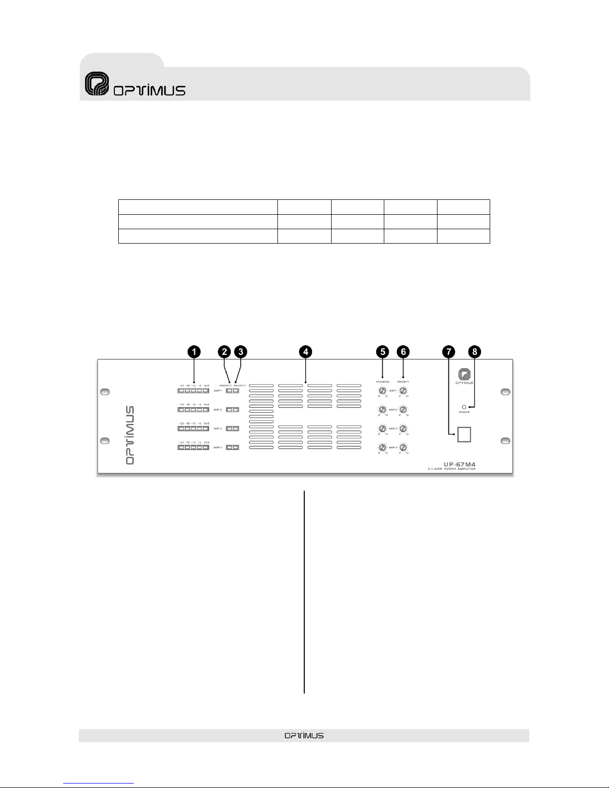
2. FRONT VIEW
(1) LEVEL INDICATORS
To indicate the power delivered to the line. The
LED marked as 0 dB indicated the maximum
power given by the amplifier.
(2) PROTECTION INDICATORS
They light when the Protection is operating due
either to an over-loading or to a short-circuit in
the loudspeakers line.
(3) PRIORITY INDICATORS
They light when the Priority channel is selected, it
is: when the pin number 6 is joined to the pin
number 8 in the RJ45 connector of the Priority
Input or when the Priority Control contact is
activated.
(4) VENTILATION INPUT. Do not obstruct
under no circumstances.
(5) PROGRAM INPUTS VOLUME CONTROLS
Turn them clockwise to increase the volume of
the Program channel. The potentiometers can be
adjusted by using a screwdriver.
(6) PRIORITY INPUTS VOLUME CONTROLS
Turn them clockwise to increase the volume of
the Priority channel. The potentiometers can be
adjusted by using a screwdriver.
(7) ON/OFF SWITCH
It switches on/off the amplifier only if the power
is supplied by the 230 V.a.c. mains. This switch is
not operational when the amplifier is supplied by
battery.
(8) ON/OFF LED INDICATOR
It lights when the amplifier is in operation, either
by Battery or Mains.
Figure 1
Page 6

UP-67M4, UP-127M4,
UP-247M2, UP-487
Modular amplifiers. v 2.3
Modular
amplifiers
6
3. REAR VIEW
(1) SECURITY PAGING AUXILIARY RELAYS
They are switched when the corresponding
priority contacts of the PRIORITY channels are
activated.
They are used to activate external elements that
have to be activated at the same time that
speech preference is in operation (i.e. Volume
controls with security paging option).
(2) LOUDSPEAKERS LINE OUTPUTS
The loudspeakers line outputs are done by means
of transformers with low impedance outputs (8
Ohm) and high impedance outputs (70-100 V).
The connection is made between the "0"
(common) terminal and the one corresponding to
the chosen impedance or voltage.
When working with the 70 and 100V lines, it
should be remembered that:
The loudspeakers to be connected must have
a line transformer.
The total connected power will be the sum of
the power absorbed by the loudspeakers and
this must be between 50% below and 20%
above the rated power of the amplifier.
The power absorbed by a loudspeaker with a
transformer is indicated on its terminals. This
power is on the 100 V line. If the transformer
is connected to the 70 V line, it will absorb
half the indicated power (see figure 3).
(3) CONNECTION TO THE 230 V.a.c. MAINS
The rear panel has a male base for the CEE22
supply which allows its connection to the mains
by means of the cable included.
Figure 2
Attention: this equipment cannot be splashed or
exposed to water.
Figure 3
A. Total input power 300 W.
Power absorbed by each
30 W transformer = 30 W
B. Total input power 300 W.
Power absorbed by each
30 W transformer = 15 W
Page 7

UP-67M4, UP-127M4,
UP-247M2, UP-487
Modular amplifiers. v 2.3
Modular
amplifiers
7
(4) MAINS FUSE
It is located into the lower
box of the power supply
base. In the same box there
is a replacement fuse as well.
(5) BATTERY
SUPPLY INPUT
This supply allows
the use of these
amplifiers in
security
installations,
connecting the
same to a 24 V.d.c.
battery.
The ON/OFF switch
doesn't cut the
supply from the
battery.
Each one of the
equipment power
units includes a 24
V.d.c. power
supply input (see
figure 4). The
connection positive
terminal is
common to the
different power
units.
ATTENTION: In
installations where
the units are power
supplied by the
battery input, IT IS
NOT POSSIBLE to
use the PROGRAM
AUDIO BUS (DIP
switch nº 10) and
PRIORITY AUDIO BUS (DIP switch nº11) DIP switches to join the different channels audio signals. The
junction must be made by means of external connections as shown in figure 5. The DIP switches 1, 2, 3
& 4 (SHIELD – GND LINK) must be OFF, and the external connection must be as shown in figure 6: pin 2
must be disconnected.
(6) GROUND CONTACT
In all P.A. installations, it is very important to have only a joining point between the signal ground and
the mains ground contact.
If the P.A. installation is made up of several equipments, they will probably have the frames joined either
by means of the ground terminal of the mains connection, or because they are mounted in a rack
cabinet.
If the grounds are also joined by the signal circuits, it is advisable to remove the jumper between the
ground and the frame of all equipments excepting one.
+24V.D.C. Power supply
positive terminal for
amplifiers 1, 2, 3 and 4
GND 2. Power supply
negative terminal for AMP. 2
GND 4. Power supply
negative terminal for AMP. 4
GND 1. Power supply
negative terminal for
AMP. 1
GND 3. Power supply
negative terminal for
AMP. 3
Figure 4
Figure 5
Figure 6
Page 8

UP-67M4, UP-127M4,
UP-247M2, UP-487
Modular amplifiers. v 2.3
Modular
amplifiers
8
(7) GROUND TERMINAL
(8) VENTILATION OUTPUT
Do not obstruct this output under no circumstances.
There is a fan in the rear panel, always in operation, changing its speed depending on the temperature
reached in the equipment.
(9) ADJUST OF OPTIONAL OSCILLATORS (OSC-02)
If the amplifier is equipped with OSC-02, that control permits to adjust the oscillation signal.
To adjust the system, follow the instructions of DALA-01/DA card. The adjustment has to be done with
the speakers line properly connected to the amplifier.
Note: In installations with surveillance through DALA-01/0B set the JPA DIP switch to ON.
(10) SURVEILLANCE
CONNECTION
These connectors are used in
installations with surveillance
through SU-114N.
Connect the SU-114N to the
power unit following the
diagram shown in figure 7.
(11) PRIORITY
CONTROL
TERMINAL BLOCK
These contacts
allow the activation
of the amplifier
priority, facilitating
the installation
wiring. The block
diagram (figure 8)
shows an example
of typical
installation.
Figure 8
Configuration:
Pri. ctrl. In DIP switch at AMP1, AMP2, AMP3 and AMP4
must be in OFF.
To transfer the audio from AMP1 to the rest of power
units the set the Pro. audio bus and Pri. audio bus from
AMP2, AMP3, and AMP4 to ON.
Figure 7
Page 9

UP-67M4, UP-127M4,
UP-247M2, UP-487
Modular amplifiers. v 2.3
Modular
amplifiers
9
(12) PRIORITY CHANNEL AND (13) PROGRAM CHANNEL
The two input channels (PROGRAM & PRIORITY) from
each amplifier use 4 RJ45 type connectors in parallel
2 to 2.
This way, they can provide signal to other power
units (see figure 9).
For the connection, you must use FTP Cat 5 cable,
which main feature is that it has very low impedance,
which allows to have an exceptionally flat frequency
response even for long distances, and to comply with
the CMRR & Crosstalk features required for the
analogical audio systems.
The signal inputs have a sensitivity of 0 dBu (775
mV). The pin number 3 provides a 24 V.d.c. voltage
which can be used to supply devices of low
consumption. The maximum intensity supplied is of
200 mA. in each channel.
In the PRIORITY channel, when joining the pin
number 6 to the pin number 8, the priority system is
activated as well as the security paging auxiliary
relay (DIP switch 7 Pri. ctrl in must be ON).
It is possible to transmit the priority control to other
power units through the pin nº 6 of the PRIORITY
OUTPUT connector (DIP switch 8 Pri. ctrl out must be
ON).
Figure 9
ATTENTION:
In order to link the program and priority audio signals
from one power stage to the other, without using
external cabling set the Pro. audio bus and Pri. audio
bus switch from AMP2, AMP3 and AMP4 in ON. In
AMP1 they must be in OFF.
To link different mainframes, it can only be used the
outputs from AMP1.
Figure 10
Page 10

UP-67M4, UP-127M4,
UP-247M2, UP-487
Modular amplifiers. v 2.3
Modular
amplifiers
10
(14) DIP SWITCHES
SHIELD - GND LINK (DIP
switches number 1, 2, 3 & 4)
These 4 DIP switches allow
removing the cable shielding
from the internal ground of the
equipment for each one of the
RJ-45 connectors. Normally they
are in ON position (shielding and
ground joined). To separate the
same, place the corresponding
DIP switch in OFF position.
PRI-PRO LINK (DIP switches
number 5 & 6)
These two DIP switches join
internally the H audio signal and
the C audio signal (when the
input is balanced) that are in the
PRIORITY OUTPUT with the
PROGRAM INPUT. Normally they
are in OFF position (separated
audio signals). To join the same,
place the corresponding DIP
switch in ON position.
PRIORITY CONTROL IN (DIP
switch number 7)
In OFF position, it disables the
priority contact of the RJ45 PRIORITY INPUT
connector in its amplifier, but the RJ45 PRIORITY
OUTPUT is still active.
PRIORITY CONTROL OUT (DIP switch
number 8)
In OFF position, it disables the priority contact of
the RJ45 PRIORITY OUTPUT connector.
PRIORITY CONTACT SURVEILLANCE (DIP
switch number 9)
When in ON, enables the priority contact
surveillance. It is necessary that the activator
follows the figure 12A (if the priority is activated
by means of RJ45 PRIORITY INPUT) or 12B (if
the priority is activated by means of PRIORITY
CTRL terminal block). When the surveillance
detects short-circuit or
open circuit in the priority
control contact the contact
number 2 of the
SURVEILLANCE connector
is activated.
PROGRAM AUDIO BUS (DIP switch num. 10)
In ON position, Links the audio input from one
stage with the audio output from the previous
stage. Allows cascade connection between
different power stages (see figure 9).
PRIORITY AUDIO BUS (DIP switch num. 11)
In ON position, Links the audio input from one
stage with the audio output from the previous
stage. Allows cascade connection between
different power stages (see figure 9).
JPA (DIP switch num. 12)
Set on ON position when the unit includes
OSC-02 oscillator circuits (installations with
DALA-01/0B).
This way, when the power unit protection is
activated, the oscillation is stopped.
Figure 11
Figure 12A
Figure 12B
Page 11

UP-67M4, UP-127M4,
UP-247M2, UP-487
Modular amplifiers. v 2.3
Modular
amplifiers
11
(15) LED PRI. CONT. SURV.
That led indicates whether the Priority contact is supervised or not. When ON means surveillance
activated (DIP switch number 9 PRIORITY CONTACT SURVEILLANCE must be ON).
4. ATTENUATORS CONNECTION
Figure 13. INSTALLATION
WITHOUT SURETY
Figure 14. 6 CHANNELS WITH
PRIORITY AND SURETY PAGING
Figure 15.
1 CHANNEL WITH PRIORITY
AND SURETY PAGING
Page 12

UP-67M4, UP-127M4,
UP-247M2, UP-487
Modular amplifiers. v 2.3
Modular
amplifiers
12
5. ONE SECTION BLOCK DIAGRAM
Page 13

UP-67M4, UP-127M4,
UP-247M2, UP-487
Modular amplifiers. v 2.3
Modular
amplifiers
13
6. TECHNICAL SPECIFICATIONS
UP-487
UP-247M2
UP-127M4
UP-67M4
R.M.S. Output power
1 x 480 W
2 x 240 W
4 x 120 W
4 x 60 W
I.H.F. Output power
1 x 585 W
2 x 312 W
4 x 175 W
4 x 87 W
Total harmonic distortion
Less than 1% at 1 kHz
Less than 1% at 1 kHz
Less than 0.6% at 1 kHz
Less than 0.6% at 1 kHz
Frequency response
55 Hz to 18 kHz
Signal / Noise ratio
>80 dB
Inputs (each section)
1 program (0 dB), 1 priority (0 dB), 1 surveillance
Inputs sensitivity
775 mV ( program and priority)
Loudspeakers line output
100 V, 70 V, 8 ohms
Controls
Program and Priority volumes
Mains supply
230 V.c.a
Mains fuse
10A
10A
10A
5A
Battery supply
24 V.d.c
Stand-by consumption
56 VA
56 VA
56 VA
28 VA
Rated output consumption
1400 VA
1400 VA
1400 VA
700 VA
Fan activation
Continuous ventilation, with variation according to the temperature speed
Dimensions (mm)
482 x 360 x 133 mm
Rack units
3 units
Weight
23.4 kg
24.3 kg
25.3 kg
20 kg
Finishing
Front panel in anodised black aluminium. Cover in black enamelled steel.
7. DOCUMENT VERSION TRACKING
Reference system
Type of Document
Confidentiality
N/A
Analogue systems
Installation and operation guide
Rev
Date
Modifications Content
Written by:
1.0
November 11
First version. Preliminary.
R&D Department
2.0
February 12
3. Rear view (2), (5), (10)
5. One section block diagram
7. Document version Tracking
Format and text style
R&D Department
2.1
April 12
3. Rear view (5)
R&D Department
2.2
April 12
3. Rear view (12 & 13)
R&D Department
2.3
September 12
Technical specifications and Opimus address list
R&D Department
Approved By
Function
Date
Ferran Gironès i Puig
R+D Director
04/2012
WARNING. This is a Class A product. In a domestic environment this product may cause radio interference in which case the
user may be required to take adequate measures.
Page 14

UP-67M4, UP-127M4,
UP-247M2, UP-487
Modular amplifiers. v 2.3
Modular
amplifiers
14
8. GUARANTEE
1. GUARANTEE CERTIFICATE
1. OPTIMUS S.A. guarantees that its products are free from material and
manufacturing defects when they are first delivered to the purchaser.
2. In accordance with the conditions outlined here, OPTIMUS S.A.
guarantees its products for two (2) years from the date on which the
purchaser acquires the product. If, within this guarantee period, defects
appear whi ch are not due to f actors outlined in section 2, OPTIMUS S.A.
shall replace or repair the unit using equivalent, new or reconstructed
replacement parts, as it deems fi t. If replacement parts are applied which
improve the unit, OPTIMUS S.A. reserves the right t o charge the client for
the additional cost of these components.
3. No guarantee benefits shall be provided other than those cited here.
4. In order to claim the guarantee rights, i t shall be an essential
requirement to present the original purchase invoice or the guarantee
certificate.
2. GUARANTEE PROVISIONS
1. In the event that the product had to be modified or adapted to
comply with local requirements concerning technical specifications or
safety, and if the country in question is not the country for which the
product was originally designed and manufactured, defects are not
considered to be material or manufacturing defects. Furthermore, the
guarantee does not cover the execution of these modifications or
adaptations, regardless of whether or not they have been carried out
correctly.
Nor shall OPTIMUS S.A. be responsible for any costs under this guarantee
for these types of modifications.
2. The guarantee shall not entitle the purchaser to inspection or free
maintenance or repair of the unit, particularly if the defects are due to
inappropriate use. Nor do the guarantee rights cover defects in wearing
parts that become worn as a result of normal wear and tear. Wearing
parts are, in particular, potentiometers, switches/keys, and similar parts.
3. The guarantee does not cover defects in the equipment unit caused
by:
Abuse or incorrect use of the unit for purposes other than those for
which it is intended, in non-compliance with the service and
maintenance instructions specified in the Manual and/or Technical
Instructions for the unit.
Connection or use of the product in a manner that does not
correspond to the technical or safety requirements of the country in
which the unit is used.
Installation in conditions other than those indicated in the Manual
and/or Technical Instructions.
Deficiency or interruptions in the electricity supply or installation
defects which imply use in abnormal conditions.
Damage caused by other equipment units that are connected to the
product.
The use or installation of Software (programmes), interfaces, parts or
supplies not provided and/or not authorised by OPTIMUS S.A.
Failure to use the original packaging for transportation.
Damage caused by force majeure or other causes not attributable to
OPTIMUS S.A.
4. The following elements are not covered by this guarantee:
All plastic surfaces and all parts exposed to outdoor conditions which
have been scratched or damaged as a result of normal or abnormal
use.
Breakages, knocks, damage due to a fall or scratches caused by
moving the unit in any way.
Damage caused by tests, use, maintenance, installation or
inappropriate adjustments, or as a result of any alteration or
modification of any kind not carried out by a Servi ce Authorised by
OPTIMUS S.A. in compliance with this guarantee.
Damage to persons or property that might be caused by the improper
use of the equipment, including lack of maintenance.
5. The guarantee shall not be valid whenever the following is observed:
Amendments or corrections made to the details of the guarantee
certificate or purchase invoice.
Failure to produce the original invoice or the absence of a date on
this.
Absence of the serial or batch number on the equipment.
6. In the case of personal computers, the guarantee will not cover the
elimination of computer vi ruses, the restoration of programmes damaged
by these or the reinstallation of the disk following its deletion.
7. The rights of this guarantee are invalidated if the product has been
repaired or opened by staff unauthorised by OPTIMUS S.A. or by the client
himself.
8. If OPTIMUS S.A. were to establish before the client that the damage
affecting the unit does not entitle a claim to be made under the
guarantee, the costs of checking the equipment incurred by OPTIMUS S.A.
shall be borne by the client.
9. Products not covered by the guarantee shall only be repaired once
payment has been effected by the client. In the event that the guarantee
rights do not apply, OPTIMUS S.A. shall duly inform the client. If, within a
period of 6 weeks from this communication, no written repair order is
received from the client confirming acceptance of the costs, OPTIMUS S.A.
shall return the unit in question to the client. In this case, the transport
and packaging costs shall be invoiced separately and payment shall be
made on delivery. In the event that a repair order is sent by the client,
confirming that he assumes the costs of repair, the transport and
packaging costs shall be invoiced additionally, and also separately.
10. If the equipment needs to be transferred to the Authorised Servi ce
Centre, transportation shall be effected by the responsible party according
to the guarantee, who will also bear the freight and insurance costs.
11. In the event of a defect, OPTIMUS S.A. guarantees that the repair
and/or replacement of parts so that the unit operates correctly will be
made within a period of no more than 30 days. Nevertheless, OPTIMUS
S.A. would like to clarify that the normal period does not exceed 30 days.
12. All parts or products replaced as part of the guarantee services shall
become the property of OPTIMUS S.A.
3. TRANSFER OF GUARANTEE
The guarantee is solely awarded to the original purchaser (principal client)
and is not transferable. With the exception of OPTIMUS S.A., no third
party (dealers, etc.) is authorised to award additional guarantees on
behalf of OPTIMUS S.A.
4. CLAIMS FOR DAMAGE
In the event that OPTIMUS S.A. cannot provide a suitable guarantee
service, the purchaser shall not be entitled to claim any indemnity for
damages arising. The responsibility held by OPTIMUS S.A. i s limited in all
cases to the invoicing price of the product.
5. RELATION WITH OTHER GUARANTEE RIGHTS AND NATIONAL
LAW
1. This guarantee does not affect the rights of the purchaser with respect
to the vendor arising from the contract of sale accomplished.
2. These conditions of the guarantee provided by OPTIMUS S.A. are valid
as long as they do not contradict the corresponding national law on
guarantee provisions.
3. OPTIMUS S.A. guarantees that this product complies with the safety
regulations in force in the country.
THIS LIMITED GUARANTEE DECLARATION IS THE EXCLUSIVE GUARANTEE
OFFERED BY OPTIMUS S.A. ALL OTHER EXPLICIT OR IMPLICIT
GUARANTEES ARE EXCLUDED, AND THIS ALSO APPLIES TO GUARANTEES
OF MARKETABILITY AND SUITABILITY FOR A PARTICULAR PURPOSE.
(EXCEPT WHEN THESE GU ARANTEES ARE REQUIRED BY AN APPLICABLE
LAW). NO GUARANTEE, EITHER EXPLICIT OR IMPLICIT, SHALL BE
APPLIED ONCE THE GUARANTEE PERIOD HAS EXPIRED
OPTIMUS S.A.
After-Sales Service
C/ Barcelona 101
17003 - GIRONA
Tel. 902 151 96 / 972 203 300
Fax. 972 21 84 13
e-mail:girona@optimus.es 1999/44/CE
 Loading...