

Page 1
Page 2

Page 3
PM-812/0
Modular system
PM-812/0 version 1.0
3
Page 4

PM-812/0
Modular system
PM-812/0 version 1.0
4
Table of contents
1. PM-812/0 MODULAR CHASSIS ............................................................................................. 5
1.1. DESCRIPTION ............................................................................................................ 5
1.2. FRONT VIEW .............................................................................................................. 5
1.3. REAR VIEW ................................................................................................................ 5
1.4. POWER SUPPLY .......................................................................................................... 6
1.5. CHASSIS GROUNDING ................................................................................................ 6
1.6. PM-812/0 BUS – INTERNAL CONFIGURATION ................................................................ 6
1.7. CASCADING CONNECTION OF SEVERAL PM-812/0 UNITS ................................................ 8
2. C-810LE INPUT CARD .......................................................................................................... 9
2.1. DESCRIPTION ............................................................................................................ 9
2.2. CONNECTION ............................................................................................................. 9
2.3. SETUP ....................................................................................................................... 9
3. C-810LS OUTPUT CARD ...................................................................................................... 11
3.1. DESCRIPCIÓN .......................................................................................................... 11
3.2. PROGRAM CHANNEL OUTPUT ..................................................................................... 11
3.3. PRIORITY CHANNEL OUTPUT ..................................................................................... 11
3.4. CONNECTION ........................................................................................................... 11
3.5. SETUP ..................................................................................................................... 12
3.6. INTERNAL CONNECTIONS ......................................................................................... 12
4. TECHNICAL FEATURES ....................................................................................................... 13
5. DOCUMENT VERSION TRACKING ....................................................................................... 13
6. GUARANTEE ....................................................................................................................... 14
Page 5
PM-812/0
Modular system
PM-812/0 version 1.0
5
1. PM-812/0 MODULAR CHASSIS
1.1. DESCRIPTION
The PM-812/0 equipment is a modular frame that can house different card models series C-700
and C-800 (preamplifiers, microphone input cards, fault detection cards, message recording playback cards, etc.).
The default configuration consists of one input card (C-810LE), one output card (C-810LS) and a bus with
12 free positions between both two cards.
The cards can occupy one or more positions, depending on the model:
2 positions: C-810PAL, C-810SAL, C-810RP1, C-810RP4...
1 position: C-810LS, C-810LE, C-810PRJ, C-810PPA...
It features a program channel, where the program signals are mixed, and a priority channel, with a
cascading priorities system.
The bus was designed so as to be divided into several sections. In this way, each section (consisting of
one or more slots per card, as required) works as an independent chassis.
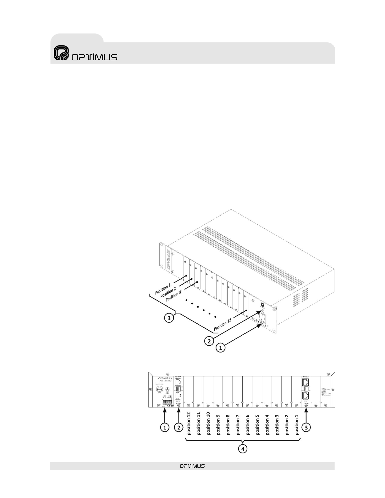
1.2. FRONT VIEW
1. ON/OFF switch.
2. ON/OFF LED indicator.
3. Blank front plates
(card positions 1 to 12).
1.3. REAR VIEW
1. Power supply plate
(see figure 3).
2. C810LS output card
(see section 3).
3. C810LE input card
(see section 2).
4. Blank rear plates
(card positions 1 to 12).
Figure 1
Figure 2
Page 6

PM-812/0
Modular system
PM-812/0 version 1.0
6
1.4. POWER SUPPLY
Use of a + 24 VDC / 3 A power supply is
recommended for the PM-812/0 (see figure 3,
number (1)).
Maximum power consumption is 2.5 A.
The power consumption varies depending on
the model and quantities of each card inserted
in the PM-812/0.
1.5. CHASSIS GROUNDING
For all P.A. systems it is very important that
there is only a single connecting point between
the signal ground and the power grounding
contact.
If the P.A. system consists of several pieces of equipment, they will probably be joined via the chassis
through a ground terminal for connection to the power supply or because they are mounted on a rack
stand.
If the grounds are also linked via the signal circuits, it is advisable to remove the jumper between the
ground and the chassis (see figure 3, number (2)) in all but one of the units.
1.6. PM-812/0 BUS – INTERNAL CONFIGURATION
The default setup of the PM-812/0 consists of an input card (C-810LE), an output card (C-810LS) and a
bus with 12 free card positions.
The cards have cascade priority, so that the card located in the OUT position has the lowest priority
ranking, followed by position 12, position 11, and so on up to position IN, which has the highest priority
ranking.
If the priority of more than one input is activated, only the signal from the card in the highest priority
position reaches the channel output.
In order to make the priority system more versatile, the bus has been designed so that it can be divided
into several sections. Thus, each section (consisting of one or more card slots as required) works as an
independent module.
To do this, the four jumpers between one slot and the next one must be cut, making one part of the bus
independent from the adjacent section. Each of the four jumpers cuts a different signal (priority audio,
program audio, priority between cards and priority bus). See figures 4 and 5.
Figure 3
Figure 4
Page 7

PM-812/0
Modular system
PM-812/0 version 1.0
7
In this way, an output card can be placed at the end of each section (in the position right before the
position where the jumpers have been disconnected) so that a PM-812/0 with 12 card positions can be
transformed into a PM-812/0 with several groups of cards, each group being independent from the rest,
and with cascade priority inside each group (see example in figure 7).
To install any card in the bus, you must remove the jumper between contacts 8 and 9 in the bus
connector (see figure 6).
The bus jumpers between card positions 4 and 5 (J34, J35, J36 and J37) and between card positions 8
and 9 (J18, J19, J20 and J21) are removed.
Two more output cards (card positions 4 and 8) are installed.
Thus, a PM-812/0 with 12 cards can be turned into three independent PM-812/0.
Figure 5
Figure 6
Card position
Priority ranking
Card position
Priority ranking
Figure 7
Page 8

PM-812/0
Modular system
PM-812/0 version 1.0
8
1.7. CASCADING CONNECTION OF SEVERAL PM-812/0 UNITS
Several PM-812/0 units can be connected in cascade form through the signal input and output cards (see
figure 8).
Any input of the card selected as priority of the first PM-812/0 (A) will have priority over any input of the
following unit – PM-812/0 (B) – and so on, preserving the range of internal priorities of each PM-812/0.
Figure 8
Page 9

PM-812/0
Modular system
PM-812/0 version 1.0
9
2. C-810LE INPUT CARD
2.1. DESCRIPTION
This card has a program and priority input, with a sensitivity of 0 dB.
The signal applied to these inputs (extension inputs) goes directly through
the bus to the output card (C-810LS).
In combination with the output card, several PM-812/0 modules can be
connected, keeping the cascade priority (see PM-812/0, section 1.7.).
2.2. CONNECTION
The card uses 8-pin RJ45 connectors with metal housing.
2.3. SETUP
Each of the two inputs has a dipswitch that is accessible from the rear plate of the card, which enables
separation of the wire shield from the ground circuit.
To separate the shield from the ground, move the dipswitch to the OFF position (dipswitch number 4 for
the program channel and dipswitch number 1 for the priority channel). See figures 11 and 12.
This is especially useful in installations with noise problems due to ground loops.
Figure 9
Figure 10
Figure 11
Figure 12
Page 10

PM-812/0
Modular system
PM-812/0 version 1.0
10
Optionally, these inputs can be connected to a balancing transformer (T700) by disconnecting jumpers J1
and J2 for program input, and J3 and J4 for priority input, and connecting the transformers as shown in
figure 13.
Figure 13
Page 11

PM-812/0
Modular system
PM-812/0 version 1.0
11
3. C-810LS OUTPUT CARD
3.1. DESCRIPCIÓN
This card has one program and one priority output. Both are of a 0 dB
sensitivity and balanced by means of a transformer.
It receives both program and priority channel signals from the bus.
The card allows connection of the oscillator card, the C-810MA microphone
card and the vu-meter card for displaying program and priority levels (see
section 3.6).
In combination with the input card, it allows connection of several
PM-812/0 modules, keeping cascade priority (see PM-812/0, section
1.7).
3.2. PROGRAM CHANNEL OUTPUT
A transformer-balanced output that provides the sum of all the signals
from cards set up as program cards and the program input of the C-810LE
card, with a level of 0 dBu.
3.3. PRIORITY CHANNEL OUTPUT
A transformer-balanced output that provides the signal from the priority activated card, with a
level of 0 dB.
If the priority of more than one input is activated, only the highest-priority input signal reaches the
priority channel output.
3.4. CONNECTION
The card uses 8-pin RJ45 connectors with metal housing.
Figure 14
Figure 15
Page 12

PM-812/0
Modular system
PM-812/0 version 1.0
12
3.5. SETUP
Each of the two channels (program and priority) has a
dipswitch that is accessible from the rear plate of the
card, which enables separation of the wire shield from
the ground circuit.
To separate the shield from the ground, move the
dipswitch to the OFF position (dipswitch number 4 for
the program channel and dipswitch number 1 for the
priority channel). See figures 16 and 17.
This is especially useful in installations with noise
problems due to ground loops.
3.6. INTERNAL CONNECTIONS
CONECTORES K1 y K2
These are two inputs used to connect the C-810MA/C-710MA microphone card.
K1: K1 is used to mix the microphone signal (0 dB) with the PM-812/0’s other program signals. The
microphone signal is output through the PROGRAM OUTPUT of the C-810LS card.
K2: K2 is used when the user wishes to give absolute priority to the microphone over all other PM-812/0
priority inputs. The microphone signal is output through the PRIORITY OUTPUT of the C-810LS card.
K3 AND K4 CONNECTORS
These connectors are used to connect the oscillator
card.
K3: Oscillator signal input for the priority channel.
The signal uses the card’s PRIORITY OUTPUT.
K4: Oscillator signal input for the program channel.
The signal uses the card’s PROGRAM OUTPUT.
K5 AND K6 CONNECTORS
These outputs are used to connect two external vumeters in order to display the program or priority
channel signal level.
K5: Displays the priority channel signal level.
K6: Displays the program channel signal level.
Figure 16
Figure 17
Figure 18
Page 13

PM-812/0
Modular system
PM-812/0 version 1.0
13
4. TECHNICAL FEATURES
PM-812/0
Power Supply
24 Vdc
Consumption (PM-812/0 + C-810LE + C-810LS)
40 mA
Dimensions (mm)
482.6 (w) x 89 (h) x 290 (d)
19” Rack units
2
Weight
4.1 Kg
Finish
Black painted iron
Tarjeta C-810LE
Program Input Sensitivity
0 dBu
Priority Input Sensitivity
0 dBu
Tarjeta C-810LS
Program output impedance
600 Ohms
Priority output impedance
600 Ohms
Program output sensitivity
0 dBu
Priority output sensitivity
0 dBu
5. DOCUMENT VERSION TRACKING
Reference system
Type of Document
Confidentiality
N/A
Analogue systems
Installation and operation guide
Rev
Date
Modifications Content
Written by:
1.0
October 12
First version
R&D Department
Approved By
Function
Date
Ferran Gironès i Puig
R&D Director
10/2012
WARNING. This is a Class A product. In a domestic environment this product may cause radio interference in which case the
user may be required to take adequate measures.
Page 14

PM-812/0
Modular system
PM-812/0 version 1.0
14
6. GUARANTEE
1. GUARANTEE CERTIFICATE
1. OPTIMUS S.A. guarantees that its products are free from material and
manufacturing defects when they are first delivered to the purchaser.
2. In accordance with the conditions outlined here, OPTIMUS S.A.
guarantees its products for two (2) years from the date on which the
purchaser acquires the product. If, within this guarantee period, defects
appear which are not due to factors outlined in section 2, OPTIMUS S.A.
shall replace or repair the unit using equivalent, new or reconstructed
replacement parts, as it deems fit. If replacement parts are applied which
improve the unit, OPTIMUS S.A. reserves the right to charge the client for
the additional cost of these components.
3. No guarantee benefits shall be provided other than those cited here.
4. In order to claim the guarantee rights, it shall be an essential
requirement to present the original purchase invoice or the guarantee
certificate.
2. GUARANTEE PROVISIONS
1. In the event that the product had to be modified or adapted to
comply with local requirements concerning technical specifications or
safety, and if the country in question is not the country for which the
product was originally designed and manufactured, defects are not
considered to be material or manufacturing defects. Furthermore, the
guarantee does not cover the execution of these modifications or
adaptations, regardless of whether or not they have been carried out
correctly. Nor shall OPTIMUS S.A. be responsible for any costs under this
guarantee for these types of modifications.
2. The guarantee shall not entitle the purchaser to inspection or free
maintenance or repair of the unit, particularly if the defects are due to
inappropriate use. Nor do the guarantee rights cover defects in wearing
parts that become worn as a result of normal wear and tear. Wearing
parts are, in particular, potentiometers, switches/keys, and similar parts.
3. The guarantee does not cover defects in the equipment unit caused
by:
Abuse or incorrect use of the unit for purposes other than those for
which it is intended, in non-compliance with the service and
maintenance instructions specified in the Manual and/or Technical
Instructions for the unit.
Connection or use of the product in a manner that does not
correspond to the technical or safety requirements of the country in
which the unit is used.
Installation in conditions other than those indicated in the Manual
and/or Technical Instructions.
Deficiency or interruptions in the electricity supply or installation
defects which imply use in abnormal conditions.
Damage caused by other equipment units that are connected to the
product.
The use or installation of Software (programmes), interfaces, parts or
supplies not provided and/or not authorised by OPTIMUS S.A.
Failure to use the original packaging for transportation.
Damage caused by force majeure or other causes not attributable to
OPTIMUS S.A.
4. The following elements are not covered by this guarantee:
All plastic surfaces and all parts exposed to outdoor conditions which
have been scratched or damaged as a result of normal or abnormal
use.
Breakages, knocks, damage due to a fall or scratches caused by
moving the unit in anyway.
Damage caused by tests, use, maintenance, installation or
inappropriate adjustments, or as a result of any alteration or
modification of any kind not carried out by a Service Authorised by
OPTIMUS S.A. in compliance with this guarantee.
Damage to persons or property that might be caused by the improper
use of the equipment, including lack of maintenance.
5. The guarantee shall not be valid whenever the following is observed:
Amendments or corrections made to the details of the guarantee
certificate or purchase invoice.
Failure to produce the original invoice or the absence of a date on
this.
Absence of the serial or batch number on the equipment.
6. In the case of personal computers, the guarantee will not cover the
elimination of computer viruses, the restoration of programmes damaged
by these or the reinstallation of the disk following its deletion.
7. The rights of this guarantee are invalidated if the product has been
repaired or opened by staff unauthorised by OPTIMUS S.A.or by the client
himself.
8. If OPTIMUS S.A. were to establish before the client that the damage
affecting the unit does not entitle a claim to be made under the
guarantee, the costs of checking the equipment incurred by OPTIMUS S.A.
shall be borne by the client.
9. Products not covered by the guarantee shall only be repaired once
payment has been effected by the client. In the event that the guarantee
rights do not apply, OPTIMUS S.A. shall duly inform the client. If, within a
period of 6 weeks from this communication, no written repair order is
received from the client confirming acceptance of the costs, OPTIMUS S.A.
shall return the unit in question to the client. In this case, the transport
and packaging costs shall be invoiced separately and payment shall be
made on delivery. In the event that a repair order is sent by the client,
confirming that he assumes the costs of repair, the transport and
packaging costs shall be invoiced additionally, and also separately.
10. If the equipment needs to be transferred to the Authorised Service
Centre, transportation shall be effected by the responsible party according
to the guarantee, who will also bear the freight and insurance costs.
11. In the event of a defect, OPTIMUS S.A. guarantees that the repair
and/or replacement of parts so that the unit operates correctly will be
made within a period of no more than 30 days. Nevertheless, OPTIMUS
S.A. would like to clarify that the normal period does not exceed 30 days.
12. All parts or products replaced as part of the guarantee services shall
become the property of OPTIMUS S.A.
3. TRANSFER OF GUARANTEE
The guarantee is solely awarded to the original purchaser (principal client)
and is not transferable. With the exception of OPTIMUS S.A., no third
party (dealers, etc.) is authorised to award additional guarantees on
behalf of OPTIMUS S.A.
4. CLAIMS FOR DAMAGE
In the event that OPTIMUS S.A. cannot provide a suitable guarantee
service, the purchaser shall not be entitled to claim any indemnity for
damages arising.
The responsibility held by OPTIMUS S.A. is limited in all cases to the
invoicing price of the product.
5. RELATION WITH OTHER GUARANTEE RIGHTS AND NATIONAL
LAW
1. This guarantee does not affect the rights of the purchaser with respect
to the vendor arising from the contract of sale accomplished.
2. These conditions of the guarantee provided by OPTIMUS S.A. are valid
as long as they do not contradict the corresponding national law on
guarantee provisions.
3. OPTIMUS S.A. guarantees that this product complies with the safety
regulations in force in the country.
THIS LIMITED GUARANTEE DECLARATION IS THE EXCLUSIVE GUARANTEE
OFFERED BY OPTIMUS S.A. ALL OTHER EXPLICIT OR IMPLICIT
GUARANTEES ARE EXCLUDED, AND THIS ALSO APPLIES TO GUARANTEES
OF MARKETABILITY AND SUITABILITY FOR A PARTICULAR PURPOSE.
(EXCEPT WHEN THESE GUARANTEES ARE REQUIRED BY AN APPLICABLE
LAW). NO GUARANTEE, EITHER EXPLICIT OR IMPLICIT, SHALL BE
APPLIED ONCE THE GUARANTEE PERIOD HAS EXPIRED.
OPTIMUS S.A.
Export Department
C/ Barcelona 101
17003 – GIRONA (SPAIN)
Tel.+34 972203300 - Fax.+34 972218413
e-mail : export@optimus.es 1999/44/CE
Page 15

Page 16

 Loading...