

Page 1

INSTRUCCIONES
DE FUNCIONAMIENTO
GUIA DEL USUARIO
OPERATING
INSTRUCTIONS
OWNER’S MANUAL
MD-20
• Antes de hacer funcionar este aparato, lea detenidamente estas instrucciones.
• Before operating this unit, please read these instructions.
PUPITRE MICROFÓNICO
MICROPHONE DESK
Page 2
MD-20 v1.2
CONTENI
D
1. INTRODU
C
2. PRESTACI
O
3. CONTROL
E
4. CONFIGU
R
5. CONEXIO
N
6. FUNCION
A
7. EJEMPLO
S
8. CARACTE
R
9. GARANTÍ
A
ATENCIÓN
Este es un
e
podría lleg
a
el usuario
d
O
CIÓN ...........
NES .............
S .................
ACIÓN .........
ES ................
MIENTO ......
DE CONEXI
Ó
ÍSTICAS TÉC
N
.................
quipo de Clas
e
r a causar ra
d
ebería tomar l
.....................
.
.....................
.
.....................
.
.....................
.
.....................
.
.....................
.
N ..................
.
ICAS ............
.
.....................
.
A. En un am
b
io interferenc
i
as medidas ad
M
....................
.
....................
.
....................
.
....................
.
....................
.
....................
.
....................
.
....................
.
....................
.
iente domésti
c
as. En este ca
s
ecuadas.
D-2
0
... 3
... 3
... 4
... 5
... 7
... 7
... 8
... 9
. 10
LI
S
1.
2.
3.
C
4.
C
5.
C
6.
O
7.
C
8.
T
9.
G
o
so WTp
u
T OF CON
T
INTRODUCTI
O
FEATURES ....
.
ONTROLS .
.
ONFIGURAT
ONNECTIO
N
PERATION .
.
ONNECTIO
N
ECHNICAL S
P
UARANTEE .
.
ARNING
his is a Class A
roduct may ca
ser may be re
q
P
ENTS
N ................
.
....................
.
....................
.
ION ..............
.
S ..................
.
....................
.
EXAMPLES ..
.
ECIFICATION
....................
.
product. In a
d
use radio inte
r
uired to take
a
UPITRE MIC
R
MICROP
H
.....................
.....................
.....................
.....................
.....................
.....................
.....................
S ...................
.....................
omestic envir
o
ference, in wh
dequate mea
s
OFÓNICO
ONE DESK
2
...................
3
...................
3
...................
4
...................
5
...................
7
...................
7
...................
8
...................
9
................. 1
0
nment this
ich case the
ures.
Page 3

MD-20 v1.2
1. INTRO
D
Este pupitre
conectado a l
o
y a los eleme
n
Dispone de u
las prioridad
e
aviso.
Se puede ali
m
externa de 9
a
2. PRESTA
C
Micrófono el
e
Gong de 4 no
t
Pulsador GON
Pulsador TAL
K
Pulsadores
c
enclavamient
o
Control de pri
Led bicolor in
d
Salida de audi
Alimentación
conector RJ4
5
fuente de
a
Phantom de
2
1 y 2).
Volumen de
G
Volumen de
m
Nivel de salid
a
Salida balanc
e
UCCIÓN
microfónico
s preamplific
a
tos de la serie
n contacto de
s del sistema
entar media
n
24 Vdc o a tra
IONES
ctret con sopo
as.
G + TALK.
.
onfigurables
.
oridad.
icador GONG
/
o a través de u
de 9 a 24 Vd
c
o bien alim
limentación.
4V a través de
ong.
icrófono.
configurable
(
ada electrónic
a
han sido di
dores y ampli
f
2600 de IMPR
O
control de pri
mientras se
e
te una fuent
e
vés del conect
o
rte flexible de
2
electrónicam
e
TALK.
n conector RJ4
, a través del
entación exte
r
Permite tam
b
l conector RJ4
5
-0 dBm / -60 d
mente.
M
señado para
icadores OPTI
M
VE.
oridad, que a
c
stá generand
o
de alimenta
c
r RJ45 de sali
d
5 cm.
nte con o
5.
contacto nº 3
na mediante
ién alimenta
c
(entre termin
Bm).
D-2
0
ser
US
tiva
un
c
ión
a.
sin
del
una
c
ión
ales
1.
Thi
th
e
IM
It
h
of
t
It
csou
2.
Ele
4 t
oGOTAL
Ele
un
l
Pri
oGOAud
9 t
oRJ4
als
o(be
Go
Mi
c
Co
n
Ele
INTRODU
C
s microphone
OPTIMUS a
m
ROVE 2600 s
e
as a priority c
o
he system whi
an be power
e
rce, or by me
a
FEATURES
ctret microph
o
nes Gong.
NG+TALK pus
h
K push-butto
n
ctronically co
n
ockable.
rity control.
NG+TALK bicol
io output thr
o
24 Vdc powe
5 connector
o
enables 24
V
tween termin
a
ng volume.
rophone volu
m
figurable out
p
ctronically bal
a
P
TION
desk has been
plifiers and p
r
ries equipmen
t
ntrol contact,
le a message i
s
d by a 9 to 2
4
ns of the outp
u
ne with 25 cm
-button.
.
figurable pus
h
our led indicat
o
ugh RJ45 conn
r supply, eithe
r
r from an ext
e
phantom po
w
ls 1 and 2).
e.
ut level (-0 dB
m
nced output.
UPITRE MIC
R
MICROP
H
designed to b
e
eamplifier, as
t
.
which activat
e
being diffuse
d
Vdc external
t RJ45 connec
t
flexible suppo
r
-buttons, eith
o
r.
ector.
from the con
t
rnal power s
u
er through
R
/ -60 dBm).
OFÓNICO
ONE DESK
3
connected t
o
well as to th
e
s the prioritie
s
.
power suppl
y
t
or.
t.
er lockable o
r
act nº 3 of th
e
pply source. I
t
J45 connecto
r
Page 4
MD-20 v1.2
3. CONTR
O
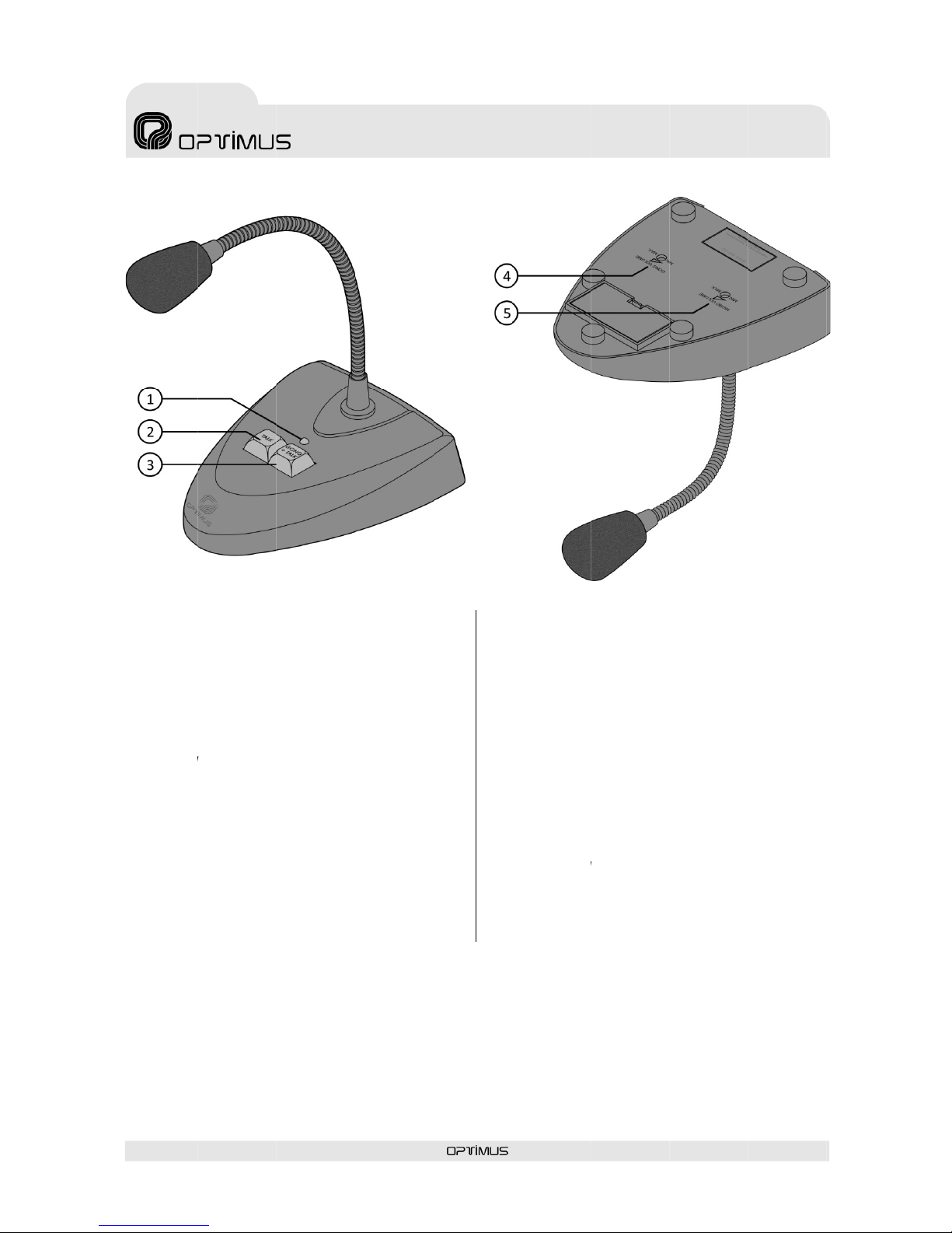
1- LED indica
d
Mientras se
e
iluminado en
verde, indica
n
2- TECLA TAL
K
Permite dar u
n
3- TECLA GO
N
Al pulsar est
a
empezar a ha
b
4- CONTROL
D
Se puede a
t
potenciómetr
o
la base.
5- CONTROL
D
Se puede a
t
potenciómetr
o
la base.
LES
or (ver Fig. 1,
n
e
stá generand
rojo. Cuand
o
do que se pue
d
(ver Fig. 1, nº
aviso sin que
G + TALK (ver
F
tecla el pup
lar.
E VOLUMEN D
enuar el vol
de ajuste, ac
E VOLUMEN D
enuar el vol
u
de ajuste, ac
º 1).
o el gong, el
ha finalizad
o
e empezar a
h
2).
se genere la s
e
ig. 1, nº 3).
itre genera el
E GONG (ver F
i
umen del g
o
cesible desde l
E MICRO (ver
F
men del mi
cesible desde l
Fig. 1
M
Led se mant
i
, cambia a c
ablar.
ñal gong.
gong y se p
u
g. 2, nº 4).
ng mediante
a parte inferio
ig. 2, nº 5).
cro mediante
a parte inferio
D-2
0
ene
olor
ede
un
r de
un
r de
3.
1-
LThegenend
2-
T
It
a
3-
G
W
h
ca
n
4-
G
Th
e
po
t
5-
M
Th
e
po
t
CONTROL
S
ED indicator (
s
led keeps lig
erated and it
ed, showing t
h
ALK KEY (see
F
llows to send
a
ONG+TALK K
E
en pressing th
start to talk.
ONG VOLUM
E
volume of t
h
entiometer ac
c
ICRO VOLU
M
volume of t
h
entiometer ac
c
P
ee Fig. 1, nº 1)
hting in red c
o
changes to gr
e
at you can sta
ig. 1, nº 2).
message with
Y (see Fig. 1, n
is key, the des
k
CONTROL (se
e
e gong can b
c
essible from t
h
E CONTROL (s
e
e micro can
b
c
essible from t
h
UPITRE MIC
R
MICROP
H
.
lour while th
e
en colour wh
rt to talk.
out gong signa
º 3).
generates th
e
Fig. 2, nº 4).
e attenuated
b
he lower side
o
e Fig. 2, nº 5).
e attenuated
he lower side
o
Fig. 2
OFÓNICO
ONE DESK
4
gong is bein
g
en the gong i
s
l.
gong and yo
u
y means of
a
f the stand.
by means of
a
f the stand.
Page 5

MD-20 v1.2
4. CONFI
G
Para configu
r
impreso. Para
tornillos A, B
y
A través de
u
siguientes pa
r
• Nivel de
apartado
4
• Velocidad
de fábrica
• Pulsador
c
enclavami
• Unión pa
n
ver apart
a
4.1. NIVE
Es posible co
n
La configurac
nivel de salid
a
JP6 (ver Fig. 4
)
4.2. COM
El puente J4
desactivación
4.3. ENC
L
El puente
J
enclavamient
o
GONG+TALK
enclavamient
o
una vez finali
z
Configuració
n
posición PUS
H
Configuració
n
posición STAR
4.4. UNI
Ó
El puente int
RJ45 de la ma
la masa del
a
separarlas ext
URACIÓN
ar el pupitr
e
ello, deben q
u
C, tal y como
i
nos puentes i
ámetros:
salida (config
u
.1).
de desactivac
i
: 4400 miliseg
u
on enclavami
e
ento; ver apar
t
talla – masa (
do 4.4).
L DE SALID
A
figurar el nive
ión de fábrica
a -60 dBm m
e
)
.
PRESOR
(ver Fig. 4) p
e
del compresor
AVAMIENT
O
3 permite
c
(hay que
o TALK ha
s
(hay que pul
s
ado el aviso, v
o
sin enclava
m
TO TALK (ver
F
con enclava
m
T AND STOP (v
e
N PANTALL
A
erno J7 permi
sa interna del
a
parato están
raiga el puent
e
, se debe a
c
itarse los tres
ndica la figura
nternos pued
e
ración de fá
b
ón del compr
e
ndos; ver apar
t
nto (configura
c
ado 4.3).
configuración
d
(OUTPUT L
E
l de salida a 0
es a 0 dBm.
diante los pue
n
rmite modific
a
.
(TALK MO
onfigurar los
mantener
p
ta finalizar
ar la tecla GO
N
lverla a pulsa
r
iento: Situar
e
ig. 4).
iento: Situar
e
e
r Fig. 4).
A
- MASA
te separar la
parato. Por d
e
unidas (puen
t
J7 (ver Fig. 4).
M
ceder al circ
pies de goma
y
3.
n configurars
e
rica: 0 dBm;
sor (configura
c
t
ado 4.2)
ión de fábrica
e fábrica: uni
VEL)
dBm o a -60
d
Puede cambi
a
tes JP1, JP3, J
P
r la velocida
d
DE)
pulsadores
ulsada la t
el aviso) o
G+TALK o TA
L
).
l puente J3 e
e
l puente J3 e
pantalla del c
a
fecto la panta
e colocado).
P
D-2
0
uito
los
los
ver
c
ión
: sin
das;
Bm.
r el
5 y
de
con
ecla
sin
K, y
n la
n la
ble
lla y
ara
4.
It
iconthr
fig
uThe
•
•
•
•
4.
1
Thi
-6
0
it t
oand
4.
2
Th
e
rel
e
4.
3
Th
emu
en
d
G
O
ag
a
Un
TA
L
Lo
c
ST
O
4.
4
Th
e
shi
de
vsep
CONFIGU
R
s required to
figure the de
s
ee rubber bas
re 3.
following par
a
Output level
4.1).
Compressor
r
milliseconds;
s
Lockable pus
h
see sec. 4.3).
Shield – grou
n
sec. 4.4).
. OUTPU
T
s model allow
dBm. The con
o
-60 dBm, yo
u
JP6 (see Fig.
4
. COMPR
E
J4 jumper (s
e
ase time.
. TALK M
O
J3 jumper all
o
st keep press
e
ed) or unloc
NG+TALK key
in).
lockable push
-
K position (se
e
kable push-b
u
P position (se
e
. SHIELD
-
internal J7
j
e
ld from the
m
ide shield an
d
arate them, r
e
P
ATION
access to th
e
k. To do so, i
t
es and the sc
r
meters can b
e
(configured e
x
elease time
(
ee section 4.2
-button (confi
g
d link (configu
LEVEL
to configure t
h
figuration ex-f
a
have to confi
g
).
SSOR
e Fig. 4) allow
s
DE
ws to configu
r
d the GONG+
T
kable push-b
u
and, once th
e
buttons: set t
h
Fig.4).
ttons: set the
Fig.4).
GND LINK
umper allows
icrophone in
ground are j
o
move the J7 ju
UPITRE MIC
R
MICROP
H
printed circ
u
is necessary
ews A, B and
configured:
-factory: 0 dB
m
configured e
x
).
ured ex-facto
r
red ex-factory:
e output level
ctory is of 0 d
ure the jumpe
to configure
t
e lockable pus
ALK key until
t
ttons (you
m
message is
e
e J3 jumper t
o
J3 jumper to
t
to separate
t
ternal mass.
B
ined (jumper i
mper (see Fig.
OFÓNICO
ONE DESK
5
it in order t
o
to remove th
e
C as shown i
n
; see sectio
n
-factory: 440
0
y: unlockable;
linked; see
at 0 dBm or a
t
Bm. To chang
e
rs JP1, JP3, JP
5
he compresso
r
h-buttons (yo
u
t
he message i
s
ust press th
e
nded, press i
t
the PUSH T
O
he START AN
D
he RJ45 cabl
e
y default, th
e
n position). T
o
4).
Page 6

MD-20 v1.2
Fig. 3
M
D-20
P
UPITRE MIC
R
MICROP
H
*
OFÓNICO
ONE DESK
6
Fig. 4
Factory setup
Page 7

MD-20 v1.2
5. CONEX
I
5.1. SALID
A
La salida de
configurable
d
(ver Fig. 5, nº
La función de
Pin 1: Sa
Pin 2: Sa
A
el
“P
Pin 3: E
nun
Pin 6: Sa
Pin 8: G
N
5.2. ENTRA
Además de
contacto 3
d
alimentación
conector de
e
Vcc (ver Fig. 5
,
6. FUNCI
O
Existen dos p
o
1. Aviso co
n
GONG+TALK
h
del gong el L
e
verde cuando
empezar a ha
b
2. Aviso sin
g
hasta finaliza
verde mientr
a
Además, est
o
configuración
4.3). En est
e
GONG+TALK)
finalizado el a
v
ONES
(OUTPUT)
audio es ba
e 0dB o -60d
1).
los contactos
d
lida de audio
H
lida de audio
C
través de los
c
micrófono pu
e
HANTOM”.
trada de alim
e
a tensión de a
l
lida control de
D (masa).
DA DE ALIM
poder alimen
t
el conector
R
Phantom (ver
ntrada para u
n
,
nº 2).
NAMIENT
O
sibilidades de
gong: Se d
e
asta finaliza
e
d se mantien
el aviso ha fi
n
lar.
ong: Se debe
r el aviso. El
s se está dand
o
s dos mod
e
del pulsador
c
e
caso, se
d
para hablar
v
iso.
lanceada, con
B, a través de
el conector es
(Hot).
(Cold).
ontactos 1 y 2
de recibir ali
m
ntación; los
m
imentación de
prioridad.
ENTACIÓN
ar el micróf
o
J45 OUTPUT
apartado 5.1
alimentador
dar un aviso:
be mantener
l aviso. Duran
t
e encendido
e
alizado, indica
mantener pul
s
Led se manti
e
el aviso.
los ofrecen
on enclavami
e
ebe pulsar l
y volver a
M
una sensibil
i
un conector
R
la siguiente:
de este cone
c
entación de
icrófonos adm
9 a 24 Vcc.
no a través
o a través
.), dispone d
e
externo de 9
a
pulsada la t
e la reproduc
c
n rojo y cam
b
ndo que se p
u
ada la tecla
T
ne encendid
o
la posibilidad
nto (ver apar
t
a tecla TAL
K
pulsarla una
D-2
0
dad
J45
tor,
tipo
iten
del
de
un
24
ecla
c
ión
ia a
ede
ALK
en
de
ado
(o
vez
5.
5.
1
Th
e
of
0The
5.
2
Fu
r
vol
th
rmicext
6.
Th
e
1.
G
O
is
p
to
ca
n
2.
M
pr
ered
Fu
r
th
emu
pr
e
CONNECTI
O
. OUTPUT
audio outpu
t
dB or -60 dB,
function of t
h
Pin 1: Audio
Pin 2: Audio
Throu
g
micro
p
PHAN
T
Pin 3: Powe
r
powe
r
Pin 6: Priori
t
Pin 8: GND (
. POWER S
U
ther to allow
t
tage by mean
s
ough phanto
m
rophone is
p
ernal power s
u
OPERATIO
N
re are two po
s
Message wi
t
NG+TALK key
laying, the led
green colour
w
start to talk.
essage with
o
ssed until the
colour while
s
thermore, the
lockable pus
h
st press the T
A
ss it again onc
e
P
NS
is balanced,
w
via an RJ45 co
n
e contacts of t
h
output signal
H
output signal
C
g
h contacts 1
hone can be
OM techniqu
e
supply inpu
t
supply voltag
e
y control outp
u
ground).
PPLY INPU
T
he reception
o
of the conta
c
power su
p
rovided with
pply between
sibilities:
h gong: Yo
u
until the mess
a
keeps lighting
hen the gong
ut gong: It is r
message is en
d
ending the me
s
se models off
e
-button (see
s
LK key (or GO
N
the message
UPITRE MIC
R
MICROP
H
ith a configur
nector (see Fi
g
he connector i
s
(Hot).
(Cold).
and 2 of this
powered by
.
; the microp
h
between 9 a
n
t.
f the require
d
t 3 of the RJ4
5
ply (see sec
t
an input con
9 to 24 Vdc (se
must keep
ge is ended.
W
in red colour,
is ended, indi
c
equired to kee
ed. The led k
e
ssage.
r the possibili
t
ection 4.3). In
G+TALK) to s
t
is ended.
OFÓNICO
ONE DESK
7
a
ble sensitivit
y
. 5, No. 1).
the following:
connector, th
e
means of th
e
ones allow
a
d 24 Vdc.
power suppl
y
connector o
r
ion 5.1), th
e
nector for a
n
e Fig. 5, nº 2).
pressed th
e
hile the gon
g
and it change
s
ating that yo
u
p the TALK ke
y
eps lighting i
n
y to configur
e
this case, yo
u
art talking an
d
Page 8

MD-20 v1.2
7. EJEMPL
O
S DE CONEXIÓN / M7. CONNE
C
D-2
0
TION EXA
M
Fig.5
Fig.
6
PLES
P
UPITRE MIC
R
MICROP
H
OFÓNICO
ONE DESK
8
Page 9

MD-20 v1.2
8. CARA
C
ALIMENTACIÓN
CONSUMO
NIVEL SALIDA / 6
0
ANCHO DE BAN
D
RELACIÓN SEÑA
L
IMPEDANCIA DE
SENSIBILIDAD MI
SEÑAL SALIDA
GONG
CÁPSULA
DIMENSIONES
F
P
PESO
ACABADO
TERÍSTICA
S
0
0Ω
A
/ RUIDO
SALIDA
CRÓFONO /
lexo
ie
TÉCNICAS
De 9
a30
0 dBm
/
300 Hz
-5560
-47 d
B
(0 dB = 1
V
4 No
tEle
25
0
122 x 1
5
1
,
Plástic
o
M
24 VDC.
mA
/
-60 dBm
15.200 Hz
dB
0 Ω
± 4 dB
V
/Pa, 1 KHz)
as inicio
ctret
mm
5 x 40 mm
4 kg
Bayblend
D-2
0
Fig.7
8.
T
POW
E
CON
S
OUT
P
FREQ
SIGN
A
OUT
P
MICR
OUT
P
GON
G
CAPS
U
DIME
WEIG
FINIS
H
Fig.8
ECHNICA
L
R SUPPLY
UMPTION
UT LEVEL / 600 Ω
UENCY RESPONSE
L / NOISE RATE
UT IMPEDANCE
OPHONE SENSITIVI
T
UT SIGNAL
LE
NSIONS
Flexible s
u
Stand
HT
ING
P
SPECIFICA
T
T
Y /
pport
UPITRE MIC
R
MICROP
H
T
IONS
9 to 24 VDC.
30 mA
0 dBm / -60 d
B
300 Hz - 15.20
0
55 dB
600 Ω
-47 dB ± 4 d
B
(0 dB = 1 V/Pa, 1
4 Notes begi
n
Electret
250 mm
122 x 155 x 40
m
1.4 kg
Baybleng plas
t
OFÓNICO
ONE DESK
9
m
Hz
KHz)
m
ic
Page 10

MD-20 v1.2
9. CONDI
C
1. CERTIFICADO
D
1. La empresa
O
de defectos en
m
original al compra
2. La empresa
condiciones aquí
adquisición del p
r
se producen defe
c
2, la empresa OP
T
de recambio equ
i
aplican piezas de
OPTIMUS S.A. s
e
componentes al c
l
3. No se conce
d
4. Para la utiliz
a
presentar la factu
r
2. DISPOSICIONE
S
1. Si el product
requisitos locales
cual el producto
f
como defecto d
e
comprende la
independienteme
OPTIMUS S.A. ta
m
de modificacione
s
2. La garantía
reparación del a
inapropiado. Los
desgaste que sea
particular, potenc
3. La garantía n
• Abuso o uso
incumplimie
n
especificada
s
• Conexión o
requisitos té
c
• Instalación
e
Instruccione
s
• Deficiencia
o
impliquen us
• Daños ocasi
o
• El uso o i
n
suministros
n
• La no utilizac
• Daños causa
d
S.A.
4. No están cu
b
• Todas las su
p
hayan sido r
a
• Las roturas,
g
cualquier na
t
• Defectos de
d
ajustes inapr
cualquier tip
o
cumplimient
o
• Los daños p
e
del equipo, i
n
5. La garantía c
a
• Enmiendas
o
de compra.
• Falta de fact
u
• Falta de nú
m
IONES DE
G
E GARANTÍA
PTIMUS S.A. gara
n
ateriales y de ma
dor.
OPTIMUS S.A. c
o
descritas, una gar
a
oducto por el com
p
tos que no sean d
e
IMUS S.A. reempl
a
valentes, nuevas
o
recambio que con
s
reserva el dere
c
iente.
erán prestaciones
ción de los derec
h
r
a de compra origi
n
DE GARANTÍA
o tuviera que ser
m
en cuanto a técnic
ue concebido y fa
material o de
f
realización de
nte de si éstas hay
a
poco asumirá cos
t
.
no dará derecho
parato, particular
m
derechos de garan
n debidos a un d
e
iómetros, interrup
t
o abarca los defect
incorrecto del ap
a
to de las instru
c
en el Manual y/o
I
uso del producto
nicos o de segurid
a
n condiciones di
s
Técnicas.
interrupciones te
n
o en condiciones a
n
nados por otros e
q
n
stalación de So
f
o proporcionados
y
ión de los embalaj
e
os por fuerza ma
y
iertos por esta gar
a
erficies de plástic
o
yadas o dañadas d
olpes, daños por
c
uraleza.
d
años derivados d
e
opiados, o derivad
o
o
no realizada por
de esta garantía.
rsonales o a la pr
o
cluyendo la falta
d
recerá de validez
c
tachaduras en lo
s
ra original o falta
d
ero de serie o lote
ARANTÍA
tiza que sus prod
u
no de obra en el
ncede a sus pr
o
ntía de dos (2) añ
o
p
rador. Si, dentro
d
bidos a razones
m
zará o reparará el
reconstruidas, se
g
tituyen una mejor
a
ho de cargar el
c
de garantía distint
a
os de garantía se
r
al o el certificado
d
odificado o adap
t
a o seguridad, si n
o
bricado originalm
e
abricación. Por l
o
estas modificaci
n sido ejecutadas
d
t
es en el marco d
e
a inspección o
m
ente si los defe
c
tía tampoco abarc
a
sgaste normal. Pi
e
ores/teclas, y piez
a
os en el equipo ca
u
rato para fines di
s
c
ciones de servic
i
nstrucciones Técni
c
de una manera q
u
d del país en el cu
a
tintas a los indic
sión eléctrica o d
e
ormales.
uipos interconecta
tware (programa
s
y
/o autorizados po
r
s originales para s
u
or u otras causas
n
ntía los siguientes
y todas las piezas
ebido al uso norm
a
aídas o ralladuras
c
pruebas, uso, ma
n
o
s de cualquier alt
e
en Servicio Autoriz
piedad que pudier
a
e mantenimiento.
uando se observe:
datos del certific
a
e fecha en la mis
m
en el equipo.
M
ctos se encuentra
n
momento de su
e
ductos, conforme
s a partir de la fe
c
e este plazo de ga
encionadas bajo el
aparato utilizando
g
ún criterio propi
o
del aparato, la e
m
oste adicional d
e
s a las citadas.
á requisito indisp
e
e garantía.
ado para cumplir
c
se trata del país
p
nte, ello no se co
n
demás, la garan
ones o adapta
c
ebidamente o no.
la garantía por es
t
antenimiento gra
t
c
tos son debidos
a
n defectos en pi
e
zas de desgaste s
s similares.
sados por:
tintos a los previs
t
i
o y de manteni
m
c
as del equipo.
e no correspond
a
a
l se utiliza el apar
a
ados en el Man
u
fectos de instalaci
ó
dos al producto.
), interfaces, pa
r
OPTIMUS S.A.
transporte.
o imputables a OP
elementos:
expuestas al exteri
l o anormal.
ausadas por trasla
tenimiento, instal
a
ración o modifica
c
ado por OPTIMUS
S
n causar el uso in
d
do de garantía o
f
a.
D-2
0
libres
ntrega
a las
c
ha de
rantía,
punto
piezas
. Si se
presa
estos
nsable
on los
ara el
sidera
tía no
iones,
t
e tipo
uito o
a uso
zas de
on, en
os, en
iento
a los
to.
al y/o
n que
tes o
TIMUS
or que
dos de
ción y
ión de
.A. en
ebido
actura
9.
G
1. G
U
1.
O
man
u
2.
I
its pr
prod
u
facto
equi
v
repla
the ri
3.
N
4.
I
to pr
e
2. G
U
1.
I
local
coun
t
desig
man
u
exec
u
they
h
Nor
s
thes
e
2.
T
main
t
inap
p
that
b
parti
c
3.
T• Aii
u• C
t
u
•
I
T
•
D
w• D
p
•
T
s• F• D
O
4.
T
•
A
b• B
u• Dac
g• D
o
5.
T• A
o• F• A
UARANTE
ARANTEE CERTIFI
C
PTIMUS S.A. gu
a
facturing defects
w
n accordance with
oducts for two (2)
y
ct. If, within this
g
rs outlined in secti
o
alent, new or r
e
c
ement parts are
a
ght to charge the c
o guarantee bene
n order to claim t
h
sent the original p
ARANTEE PROVISI
n the event that t
h
requirements co
n
ry in question is
ned and manufac
facturing defects
.
tion of these mo
d
ave been carried
o
hall OPTIMUS S.A
.
types of modificat
he guarantee s
h
enance or repair
ropriate use. Nor
ecome worn as
a
ular, potentiomet
e
he guarantee doe
s
buse or incorrect
s intended, in
n
nstructions specifi
nit.
onnection or use
he technical or s
a
sed.
nstallation in con
d
echnical Instructi
o
eficiency or inter
hich imply use in
a
amage caused
b
roduct.
he use or install
upplies not provid
ailure to use the
o
amage caused b
PTIMUS S.A.
he following elem
ll plastic surfaces
een scratched or
d
reakages, knocks,
nit in any way.
amage caused b
y
djustments, or as
arried out by a Se
r
uarantee.
amage to person
s
f the equipment, i
he guarantee shal
mendments or co
r purchase invoic
e
ailure to produce
t
bsence of the seri
P
E
ATE
rantees that its
p
hen they are first
d
the conditions ou
t
ears from the dat
e
g
uarantee period,
n 2, OPTIMUS S.A
constructed repl
a
pplied which imp
r
lient for the additi
o
fits shall be provid
e
e guarantee right
s
urchase invoice or
t
ONS
e product had to
b
cerning technical
not the country
f
tured, defects ar
e
Furthermore, t
h
ifications or adap
t
ut correctly.
be responsible f
o
ions.
all not entitle t
h
of the unit, pa
r
do the guarantee
result of normal
w
rs, switches/keys,
a
not cover defects
use of the unit for
p
on-compliance
w
ed in the Manual
of the product in
a
fety requirement
s
itions other than
t
ns.
ruptions in the el
e
a
bnormal conditio
n
y other equipme
n
ation of Softwar
e
ed and/or not auth
riginal packaging f
o
y force majeure
o
ents are not cover
e
and all parts expo
s
amaged as a resul
t
damage due to a
f
tests, use, main
t
a result of any alt
e
vice Authorized by
or property that
m
ncluding lack of m
a
l not be valid when
rrections made to
t
.
he original invoice
al or batch numbe
r
UPITRE MIC
R
MICROP
H
roducts are free
f
elivered to the pu
r
t
lined here, OPTIM
on which the pur
c
defects appear w
h
. shall replace or r
e
cement parts, a
s
ove the unit, OPT
nal cost of these c
o
d other than thos
e
, it shall be an es
s
t
he guarantee cert
i
e modified or ada
p
specifications or
or which the pro
d
not considered
e guarantee do
e
ations, regardless
r any costs under
e purchaser to
i
ticularly if the d
e
rights cover defec
t
w
ear and tear. W
e
a
nd similar parts.
in the equipment
u
urposes other tha
ith the service
and/or Technical I
manner that doe
s
of the country i
n
hose indicated in
t
ctricity supply or
s.
t units that are
(programmes), i
n
orized by OPTIMU
S
r transportation.
r other causes
n
d by this guarante
e
ed to outdoor co
n
of normal or abn
o
all or scratches ca
u
enance, installatio
ration or modifica
t
OPTIMUS S.A. in c
o
m
ight be caused b
y
intenance.
ever the following
i
he details of the g
u
or the absence of
a
on the equipment
OFÓNICO
ONE DESK
10
f
rom material an
d
chaser.
US S.A. guarantee
s
haser acquires th
e
ich are not due t
o
pair the unit usin
g
it deems fit. I
f
IMUS S.A. reserve
s
mponents.
cited here.
ential requiremen
t
ficate.
ted to comply wit
h
safety, and if th
e
uct was originall
y
to be material o
r
s not cover th
e
of whether or no
t
this guarantee fo
r
nspection or fre
e
fects are due t
o
s in wearing part
s
aring parts are, i
n
nit caused by:
n those for which i
t
and maintenanc
e
nstructions for th
e
not correspond t
o
which the unit i
s
t
he Manual and/o
r
installation defect
s
connected to th
e
terfaces, parts o
r
S.A.
ot attributable t
o
:
ditions which hav
e
rmal use.
sed by moving th
e
n or inappropriat
e
ion of any kind no
t
mpliance with thi
s
the improper us
e
i
s observed:
arantee certificat
e
date on this.
.
Page 11

MD-20 v1.2
6 En el caso d
e
informáticos, res
t
disco provocada
p
7. Los derecho
s
abierto por un pe
r
8. Si la empres
a
daños presentad
o
las prestaciones
d
cargo del cliente.
9. Los product
o
gastos por el clie
n
informará al clie
n
comunicación, no
aceptación de lo
s
cliente. En este
c
separado y se co
b
de reparación, co
n
de embalaje se fa
c
10. En caso de
transporte será r
e
gastos de flete y s
11. En caso de
f
reposición de par
t
días. No obstante
,
12. Todas las pi
garantía pasarán
a
3. TRANSFERENCI
La garantía se co
n
y es intransferibl
e
(comerciantes, et
c
de la empresa OP
T
4. RECLAMACION
En caso de que
O
adecuado, el co
m
alguna por daño
s
OPTIMUS S.A. se l
5. RELACIÓN C
O
NACIONAL
1. Mediante esta
vendedor deduci
d
2. Las presentes c
o
siempre que no c
o
las disposiciones
d
3. OPTIMUS S.A.
a
vigentes en el paí
s
ESTA DECLARACI
Ó
OFRECIDA POR O
IMPLÍCITA, INCLU
I
DETERMINADO. (
E
UNA LEY APLICA
B
APLICARÁ TRAS L
A
OPTIMUS S.A.
Servicio Post Ven
t
C/ Barcelona 101
17003 - GIRONA
Tel. 972 203 300
Fax. 972 218 413
e-mail: girona@o
p
ordenadores P.C.,
auración de progr
a
or el borrado del
m
s
de garantía se
a
sonal no autorizad
OPTIMUS S.A. es
t
s no dan derecho
a
e revisión por pa
r
s sin derechos de
g
te. En caso de aus
e
te al respecto. Si,
recibimos ninguna
gastos, OPTIMU
S
aso, los gastos d
e
rarán contra ree
m
firmando la asun
c
turarán adicional
m
necesidad de tra
s
alizado por el resp
o
eguro.
f
alla, OPTIMUS S.
A
es para su correct
o
se deja aclarado q
ezas o productos
ser propiedad de
O
A DE LA GARANTÍ
A
cede únicamente
p
. Con excepción d
e
.) está autorizado
IMUS S.A.
ES POR DAÑOS Y P
PTIMUS S.A. no
p
prador no tendrá
y perjuicios cons
e
imita en todo caso
N OTROS DEREC
H
garantía no se af
e
os del contrato de
o
ndiciones de gara
ntradigan el derec
e garantía.
segura que este p
r
.
Ó
N DE GARANTÍ
A
PTIMUS S.A. SE E
X
DAS LAS GARANTÍ
A
XCEPTO CUANDO
LE). NINGUNA GA
FINALIZACIÓN DE
L
a
timus.es
la garantía no cub
r
mas por este mo
t
ismo.
nulan si el prod
u
o OPTIMUS S.A. o
p
ableciera al comp
r
la reclamación d
e
te de la empresa
O
arantía sólo se rep
ncia de derechos
d
en un plazo de 6
s
orden de reparaci
ó
S.A. devolverá e
transporte y em
bolso. En caso de
ión de los gastos, l
ente, igualmente
p
lado al Centro d
e
o
nsable de la gara
n
. asegura al com
p
funcionamiento
e
ue el plazo usual n
o
sustituidos al am
p
O
PTIMUS S.A.
ara el comprador
e
la empresa OPTI
M
a conceder garant
í
ERJUICIOS
ueda proporciona
ningún derecho a
cuentes. La respo
n
al precio de factur
a
OS DE GARANT
Í
cta a los derecho
s
compraventa conc
l
ntía de la empresa
ho nacional corres
p
oducto cumple co
n
LIMITADA ES L
A
CLUYE TODA OTR
A
S DE COMERCIALI
DICHAS GARANTÍA
RANTÍA, YA SEA E
X
PERIODO DE GAR
A
M
irá la eliminación d
ivo o la reinstalac
i
cto ha sido repa
r
or el propio client
e
ador del aparato
q
la garantía, los co
s
O
PTIMUS S.A. cor
r
ararán contra pag
o
e garantía, OPTIM
U
s
emanas a partir
d
ó
n escrita confirm
a
l aparato en cues
t
balaje se facturar
á
expedición de una
os gastos de trans
p
or separado.
Servicio Autoriz
a
tía, y serán a su ca
rador la reparaci
ó
n un plazo no may
o
supera los 30 día
s
aro de los servi
c
original (cliente pri
US S.A., ningún
t
í
a adicionales en n
r un servicio de g
a
reclamar indemn
i
sabilidad de la e
m
ción del producto.
A Y CON EL DE
R
del comprador fr
e
uido.
OPTIMUS S.A. son
v
ondiente en relaci
las normas de se
g
GARANTÍA EXC
L
GARANTÍA EXPLÍ
C
DAD Y APTITUD A
U
S SEAN REQUERID
A
PLÍCITA O IMPLÍCI
A
NTÍA.
1999/44/CE
D-2
0
e virus
ón del
ado o
.
ue los
tes de
erán a
de los
S S.A.
e esta
ndo la
t
ión al
n por
orden
orte y
do, el
rgo los
n y/o
r a 30
.
ios en
ncipal)
ercero
ombre
rantía
zación
presa
ECHO
nte al
v
álidas
ón con
uridad
USIVA
ITA O
N FIN
S POR
TA, SE
6.
I
elimi
n
thes
e
7.
T
or op
8.
I
affec
t
costs
clien
t
9.
P
has
b
appl
y
from
confi
r
ques
t
invoi
c
repai
the
t
sepa
r
10.
I
trans
guar
a
11.
I
repla
perio
that
t
12.
A
beco
m
3. TR
A
The
g
not t
etc.)
i
4. CL
A
In th
e
purc
h
resp
o
the p
5. RE
L
1. Th
i
vend
o
2. Th
e
as t
h
provi
3. O
regul
a
THIS
OFFE
EXCL
U
SUIT
A
ARE
R
IMPL
I
OPTI
M
After
-
C/ Ba
1700
3
Tel.
9
Fax.
9
e-ma
n the case of p
e
ation of comput
e
or the reinstallati
o
he rights of this g
u
ened by staff unau
t
f OPTIMUS S.A.
w
ing the unit does
n
of checking the eq
.
roducts not cover
e
een effected by t
h
, OPTIMUS S.A. sh
this communicati
o
ming acceptance
ion to the client.
I
ed separately and
r order is sent by t
h
ransport and pac
ately.
f the equipment n
e
portation shall b
e
ntee, who will als
o
n the event of a
d
c
ement of parts s
o
d of no more than
3
he normal period
d
ll parts or prod
u
e the property of
A
NSFER OF GUAR
A
uarantee is solely
a
ransferable. With
t
s authorized to aw
IMS FOR DAMAG
E
event that OPTI
M
aser shall not be
e
nsibility held by O
P
roduct.
L
ATION WITH OTH
E
i
s guarantee does
n
r arising from the
se conditions of t
h
ey do not cont
r
s
ions.
PTIMUS S.A. gua
r
a
tions in force in t
h
LIMITED GUARA
N
RED BY OPTIMUS
S
DED, AND THIS
A
BILITY FOR A PAR
T
EQUIRED BY AN
A
CIT, SHALL BE APP
L
US S.A.
-
Sales Service
rcelona 101
- GIRONA
72 203 300
72 218 413
il: girona@optimus
P
rsonal computers
r viruses, the res
t
n of the disk follo
w
arantee are invali
d
t
horized by OPTIM
U
ere to establish
ot entitle a claim
uipment incurred
b
e
d by the guarante
e
e client. In the e
v
all duly inform the
n, no written re
p
of the costs, OP
T
n this case, the t
r
payment shall be
e client, confirmi
n
kaging costs shall
e
eds to be transfe
r
effected by the
bear the freight a
n
efect, OPTIMUS S
.
that the unit op
e
3
0 days. Neverthel
e
oes not exceed 30
cts replaced as
p
OPTIMUS S.A.
NTEE
warded to the ori
g
he exception of
O
ard additional guar
US S.A. cannot pr
o
ntitled to claim a
n
TIMUS S.A. is limit
E
R GUARANTEE RI
G
ot affect the right
s
contract of sale ac
c
e guarantee provi
d
adict the corres
p
antees that this
e country.
TEE DECLARATI
O
.A. ALL OTHER EX
P
LSO APPLIES TO G
T
ICULAR PURPOSE
.
PPLICABLE LAW).
IED ONCE THE GU
A
.es
UPITRE MIC
R
MICROP
H
, the guarantee
w
oration of progra
m
ing its deletion.
ated if the produc
t
S S.A. or by the cli
before the client
to be made under
y OPTIMUS S.A. s
h
e shall only be rep
a
ent that the guar
a
client. If, within a
air order is receiv
IMUS S.A. shall
r
ansport and pack
a
made on delivery.
g that he assumes
be invoiced add
red to the Authori
responsible part
y
d insurance costs.
A. guarantees tha
t
rates correctly wil
l
ss, OPTIMUS S.A.
w
days.
art of the guara
n
inal purchaser (pri
PTIMUS S.A., no t
h
antees on behalf o
f
vide a suitable gu
a
y indemnity for d
a
ed in all cases to t
h
HTS AND NATION
s
of the purchaser
omplished.
ed by OPTIMUS S
.
onding national
l
product complie
s
N IS THE EXCL
U
LICIT OR IMPLICI
T
UARANTEES OF M
(EXCEPT WHEN T
H
NO GUARANTEE,
E
RANTEE PERIOD
H
1
9
OFÓNICO
ONE DESK
11
ill not cover th
e
mes damaged b
y
has been repaire
d
ent himself.
that the damag
e
the guarantee, th
e
all be borne by th
e
ired once paymen
t
ntee rights do no
t
period of 6 week
s
ed from the clien
t
eturn the unit i
n
ging costs shall b
e
In the event that
a
the costs of repair
,
itionally, and als
o
zed Service Centre
,
according to th
e
the repair and/o
r
be made within
a
ould like to clarif
y
tee services shal
ncipal client) and i
s
ird party (dealers
,
OPTIMUS S.A.
rantee service, th
e
mages arising. Th
e
e invoicing price o
f
AL LAW
with respect to th
e
A. are valid as lon
g
aw on guarante
e
with the safet
y
SIVE GUARANTE
E
GUARANTEES AR
E
ARKETABILITY AN
D
ESE GUARANTEE
S
ITHER EXPLICIT O
R
AS EXPIRED.
99/44/CE
,
l
Page 12

V1.2 14/05/2015
Page 13

C
F
A
A
MD-20. Addend
a
ONFIGUR
A
UNCIONA
M
CKNOWLE
D
CKNOWLE
D
Fig. 3
0615
CION / CO
N
IENTO EN
GE (ACK)
/
GE (ACK)
M
FIGURATI
O
MODO
ODE OP
E
Fig. 4
*
Factory
s
M
ON
RATIO
N
etup
D-20
PUPITRE M
I
MICRO
P
Modo AC
K
Permite si
n
pupitre m
i
elemento
s
activación
evitando l
a
señal inici
a
posibles r
e
activación
ACKNOW
L
Allows to
s
micropho
n
external e
l
zones acti
v
the loss of
due to po
s
the activa
t
CROFÓNICO
HONE DES
K
1
NOWLEDGE
cronizar el
crofónico con
externos de
de zonas,
perdida de
l debido a
tardos en la
.
EDGE mode
ynchronize th
e
e desk with
ements of
ation, to avoi
d
initial signal
sible delays in
ion.
Page 14

EMP
P
C
E
p
m
c
e
oe1
E
a
e
MD-20. Addend
a
JEMPLOS
D
ÓDULO
RIORIDAD
UPITRES
ASCADA
n esta config
u
rioritaria es la
ás de un pu
p
onectado a la
e
l mensaje. Los
cupado (led
n
nviar avisos.
st
IN 1st
n esta configu
ctiva. Los pupi
ncendido nara
n
0615
E CONEX
I
MPP-94.
FIRST IN
F
ración, la en
1 y la que tie
n
itre intenta
e
ntrada más p
r
pupitres de m
e
aranja encen
d
ración, tiene
p
tres restantes
ja) indicando
q
ÓN. INST
A
VARIOS
IRST O CA
S
trada del mó
d
e menor prio
nviar un me
n
ioritaria es qui
nor prioridad
ido) indicand
o
rioridad el pu
reciben la señ
a
ue no puede
n
M
LACIÓN C
O
MD-20 C
O
CADE EN
T
ulo MPP-94
ridad la 6. Cua
saje, el que
e
en consigue e
n
reciben la señ
a
que no pu
e
pitre que ante
l de ocupado
enviar avisos.
D-20
N
N
RE
más
ndo
sté
viar
l de
den
s se
(led
C
O
M
P
R
AM
CA
S
In
t
is t
th
ahiglowind
1
st
In
Th
eind
NNECTIO
N
PP-94 M
O
IORITY I
N
ONGST T
H
S
CADE
his configurati
he input 1, an
d
n a desk tryin
g
hest priority i
n
er priority d
e
icating that th
e
IN 1st
this configura
t
remaining d
icating that th
e
EXAMPL
ES
DULE: S
E
CASCA
D
E MICRO
P
on, the highes
t
the lowest pri
to send a me
s
put is who g
sks receiving
y cannot send
ion overrides
t
esks receive
a
y cannot send
PUPITRE M
I
MICRO
P
. INSTALL
A
VERAL
M
E OR FI
R
HONES
priority input
ority is the inp
sage, which is
c
ets to send t
h
a busy signal
messages.
the desk that
busy signal
messages.
CROFÓNICO
HONE DES
K
2
TION WI
T
D-20 WI
T
ST-IN-FIR
S
module MPP -
9
ut 6. When m
o
onnected to t
h
e message. T
h
(orange LED l
is active befo
r
(LED lit oran
g
H
H
T
4
re
e
e
it)
e.
e)
 Loading...