

Page 1
g
g
HTS-102 Home Theater System
Cat. No
.
31-3043
Your HTS-102 home theater system includes the STAV3770 receiver (RadioShack 31-3042, with its owner’s manual and accessories), two front speakers, two surroundsound (rear) speakers, one center spe aker, and one subwoofer. All you need to add to have a com plete hom e t heater system are an audio/video input source (s tereo Hi-Fi
VCR or DVD/LD player) and a TV.
For receiver instructions and the HTS-102’s warranty, refer
to the STAV-3770 Owner’s Manual. The instructions on
the next few pages only cover basic home theater and
speaker connections. Before making any connections, see
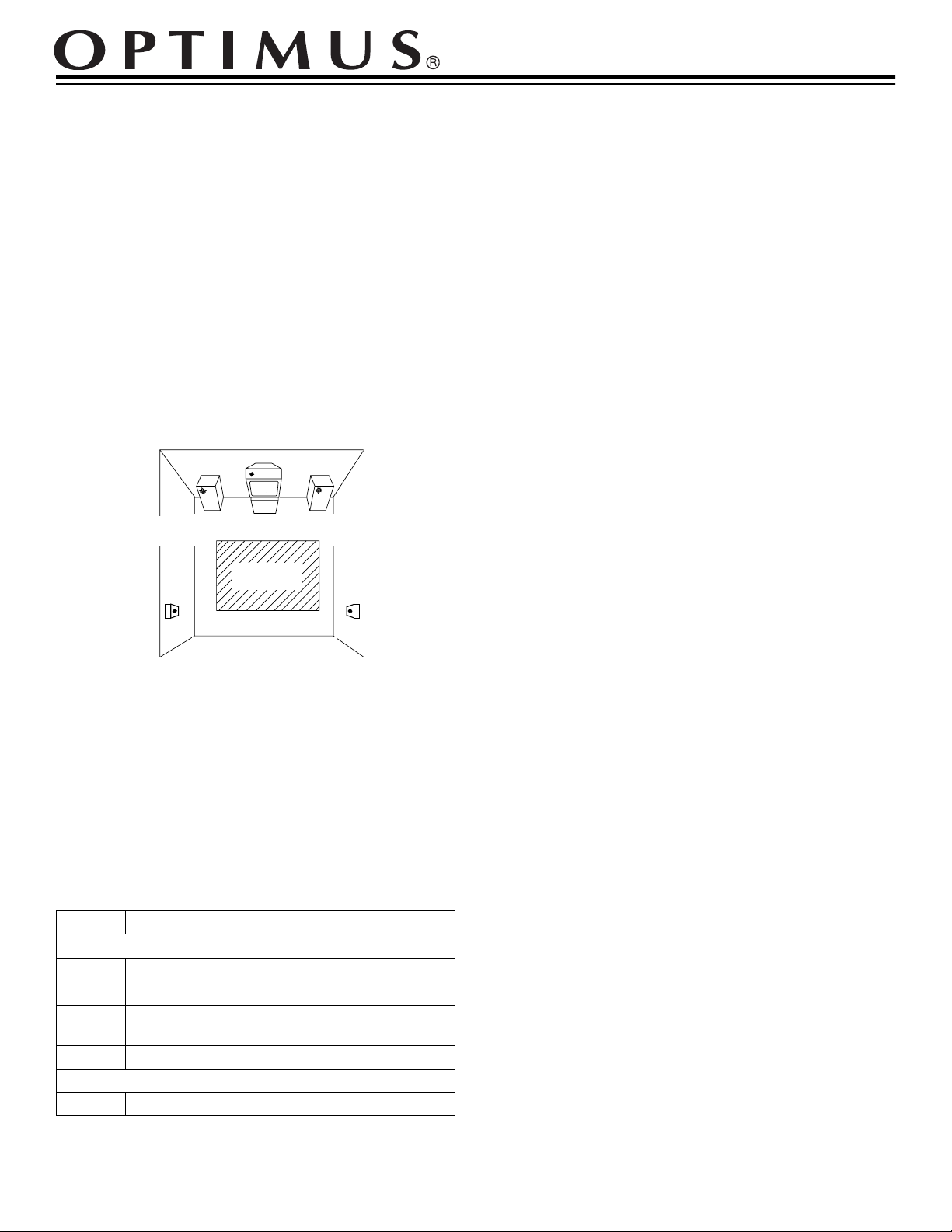
“Positioning Speakers” on Page 5 of the STAV-3770 Owner’s Manual to choose the be st locations for your speakers.
Center Speaker
TV
Front Left
Speaker
Rear Left
Speaker
Listening
Area
Front Right
Speaker
Rear Right
Speaker
Caring for Your Speakers
• Use a polishing cloth or dry cloth to wipe off dust and
dirt.
• If the cabinet is very dirty, wipe it with a soft cloth
dipped in a neutral cleanser diluted with water, then
wipe again with a dry cloth. Do not use furniture wax
or cleaners.
• Never use thinner, benzene, insecticide sprays, or
other chemicals on or near the cabinets.
• Never use a vacuum cleaner to clean the grille cloth.
Connecting Speakers
Your HTS-102 system includes all speaker wires required
for speaker connections. Each speaker wire consists of
two conductors (individual wires) encased in insulation
and is color-coded so you can identify each conductor (the
color mark is on only one of the conductors in each speaker wire pair). Use these colors as a guide to help you properly connect the speakers.
If the supplied speaker wires are too short for your connections, you can purchase additional wire at your local
RadioShack store. Use 16-gaug e (or larger) speaker wire
for all speaker connections.
Speaker Specifications
Power Handling (all speakers) ................ 35W RMS, 105W MAX
Nominal
Impedance..... .. .....8 Ohms........ 16 Ohms....8 Ohms 2 Ch (L/R)
Sensitivity.............. 86.5 dB ...........86 dB
Front/Center Rear Subwoofer
Supplied Accessories
Quantity Description Colors
Speaker Wires
2 Receiver Out to Subwoofer In Li
2 Subwoofer Out to Front Speakers Dark Blue/Red
2 Receiver Out to Surround-Sound
Speakers
1 Receiver Out to Cent er Speaker Yellow
Patch Cable
1 VCR Out to Receiver In Red/White
ht Blue/Pink
Green/Oran
e
When connecting each conductor to a speaker terminal,
hold down the terminal lever, insert the conductor’s end
into the small hole, and release the terminal le ver to secure the conductor.
When connecting each conductor to the receiver, press
open the terminal lever, insert the conductor’s end into the
small hole, and press the lever closed to secure the conductor.
Notes:
• Be sure you connect the receiver ’s right and lef t positive (+) and negative (–) terminals to the speaker’s
corresponding right and l eft positive (+) and negative
(–) terminals.
• Do not connect two pairs of speakers to a single set of
terminals.
• Surround speakers generally sound best if you position them above ear level.
© 1998 Tandy Corporation.
RadioShack and Optimus are registered trademarks used by Tandy Corporation.
All Rights Reserved.
Page 2
PHONO
TAPE2
MONITOR
CD
DVD/
LD
VCR/
TAPE1
SIGNAL GND
IN PLAY
IN OUT
IN OUT
REC IN IN PLAY REC
L
R
L
R
VIDEOINVIDEOINPRE
OUT
CONTROL
OUT
VIDEO
OUT
TO MONITOR TV
VIDEO
OUT
SUB
WOOFER
L
R
REC PLAY
AUDIO
REC
PLAY
INPUT OUTPUT
L
VCR
VIDEO
IN
OUT
L
R
R
ANTENNA
IN
ANTENNA
IN
Connecting Your VCR to Your TV
ANTENNA
IN
VIDEO
AUDIO
REC PLAY
RF OUT
VCR
REC
INPUT OUTPUT
If you have a VCR already connected to your TV, proceed
to “Connecting Your Receiver to Your VCR.”
Otherwise, connect your VCR’s ANTENNA OUT/RF OUT
jack to your TV’s ANTENNA IN/RF IN jack with a coaxial
antenna cable (one should have bee n supplied wi th your
VCR).
OUT
L
IN
R
PLAY
Connecting Your Receiver to
Your VCR
Using the supplied patch cable, connect the receiver’s
VCR/TAPE1 IN PLAY
AUDIO OUT jacks.
jacks to your VCR ’s AUDIO PLAY or
See “Preparing Y our Receiver” on Page 9 of the STAV-3770 Owner’s Manual to hook up four more external audio/video sources (a CD player, for example) to your receiver.
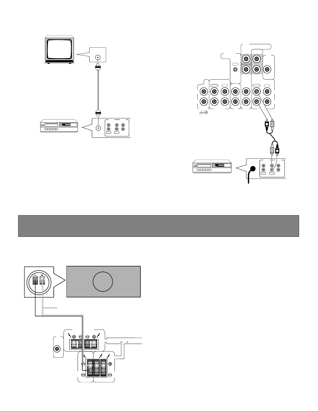
Connec ti ng the C en te r Spea ker
1. Connect the yellow conductor to the receiver’s
TER SPEAKER
(+) red terminal.
2. Connect the other conductor to the receiver’s
SPEAKER
(–) black terminal.
3. Connect the yellow conductor’s other end to the cen-
+
ter speaker’s positive (
) red terminal.
4. Connect the other conductor’s end to the center
–
speaker’s negative (
) black terminal.
2
SUB
WOOFER
PRE
OUT
Yellow
FRONT SPEAKERS
CENTER
SPEAKER
R
L
R
L
R
L
CAUTION:
SPEAKER IMPEDANCE
8 ~ 16 / SPEAKER
SURROUND
SPEAKERS
CEN-
CENTER
Page 3

Connecting the Subwoofer and Front Speakers
Pink
OUTPUT
RIGHT LEFT
INPUT
RIGHT LEFT
Light Blue
Red
FRONT SPEAKERS
Caution:
SUB
WOOFER
PRE
OUT
Do not connect the subwoofer to the receiver’s
CENTER
SPEAKER
R
L
CAUTION:
8 ~ 16 / SPEAKER
R
L
R
L
SUBWOOFER PRE OUT
its own amplifier.)
Follow these steps to connect the subwoofer and the front speakers.
1. Connect the dark blue conductor to the receiver’s
2. Connect the other conductor to the receiver’s
FRONT SPEAKERS L (+
FRONT SPEAKERS L (–
3. Connect the dark blue conductor’s other end to the subwoofer’s
4. Connect the other conductor’s end to the subwoofer’s
INPUT LEFT
5. Using the red wire, repeat S teps 1– 4 t o c onnect the subwoofer’s
ERS
right terminals.
Dark Blue
SPEAKER IMPEDANCE
SURROUND
SPEAKERS
jack. (The supplied subwoofer does not have
) red terminal.
) black terminal.
INPUT LEFT
red terminal.
black terminal.
INPUT RIGH T
terminals to the rec eiver ’s
FRONT SPEAK-
6. Connect the light blue conductor to the subwoofer’s
7. Connect the other conductor to the subwoofer’s
OUTPUT LEFT
OUTPUT LEFT
red terminal.
black terminal.
8. Connect the light blue conductor’s other end to the left front speaker’s positive (
–
9. Connect the other conductor’s end to the left front speaker’s negative (
10. Using the pink wire, repeat Steps 6–9 to connect the subwoofe r’s
) black terminal.
OUTPUT RIGHT
termi na ls.
3
+
) red terminal.
terminals to the right front speaker’s
Page 4

Connecting the Surround-Sound (Rear) Spe akers
FRONT SPEAKERS
SUB
WOOFER
PRE
OUT
CENTER
SPEAKER
R
L
CAUTION:
SPEAKER IMPEDANCE
8 ~ 16 / SPEAKER
R
L
SURROUND
SPEAKERS
R
L
Orange Green
1. Connect the green conductor to the receiver’s
2. Connect the other conductor to the receiver’s
3. Connect the green conductor’s other end to the left surround speaker’s positive (
4. Connect the other conductor’s end to the left surround speaker’s negative (
SURROUND SPEAKERS L (+
SURROUND SPEAKERS L (–
) red terminal.
) black terminal.
+
) red terminal.
–
) black terminal.
5. Using the orange wire, repeat Steps 1–4 to conne ct the right surround speak er to the receiver ’s
right terminals.
SURROUND SPEAKERS
Wall Mounting the Speakers
To mount the speakers on a wall, you need wood screws with heads that fit into the keyhole slot on the back of each speaker. Make sure the wall surface and screws you use are ap propriate for the weight of the speakers. Keep in mind that the
speaker’s vibration will a ffect the surfac e, so we do not recommend mounting on plywood boards or other soft-surface
walls.
Drill a hole and thread a screw in to the wall, letting the head extend about
slot with the mounting screw and slide the speaker downward to secure it.
1
/4"
Mounting
Screw
Keyhole Slot
1
/4 inch (6 mm) from the wall. Align the keyhole
Wall Wall
Gap
Incorrect Correct
RadioShack
A Division of Tandy Corporation
Fort Worth, Texas 76102
4A8 Printed in the USA
 Loading...