

Page 1
Cat. No.
Audio/Video
Receiver
STAV-3690
31-3040
SFC
MODE
POWER
PHONES
STAV-3690 AUDIO/VIDEO RECEIVER
STAND BY
DOLBY
PRO LOGIC
THEATER
VIDEO INPUT
VIDEO L AUDIO R
5-D
LOUDNESS
DSP
DIGITAL
SIGNAL
PROCESSOR
BASS
OSR
TREBLE
BALANCE
SPEAKERS MEMORY FM/AM ENTER
RL
BA
SELECTCLASSFM MONORETURN
VCR
TAPE 1
INTELLIGENT SYSTEM REMOTE
DVD/TV
LD/SAT
CD TUNER
MULTI
JOG
PHONO
DOLBY SURROUND
PRO•LOGIC
TAPE 2
MONITOR
VOLUME
MAXMIN
Owner’s Manual
Please read before using this equipment.
Page 2

Introducing the Optimus STAV-3690
Your Optimus STAV-3690 Audio/Video Receiver is the perfect control center for
your audio/video system. It combines 500 watts total Pro Logic‘ Surround
Sound power with five equal-power discrete amplifiers, and provides connections for one tape deck, one VCR, two more tape decks or audio/video playback
sources, a turntable, a CD player, and a video monitor, plus front panel audio/
video input jacks for connecting one more audio/video device such as a camcorder.
Digital-Synthesized Tuner
30 Memory Locations
Multi-J og Tuning
Subwoofer Output
Tape Monitoring
Built-In Protection Circuits
Your receiver also has special sound options.
Dolby Pro Logic Surround Sound
delivers movie theater sound for audio/video programs (especially those encoded with Dolby Surround Sound signals).
sound field than ordinary playback.
SFC Effects
Dolby 3CH Logic
provides a wider
creates a listening environment
that simulates a concert hall, jazz club, recording studio, or a live performance.
5D Theater
provides clear dynamic sound effects by sending audio signals
through the rear channel to simulate stereo sounds.
Additional features include:
Precisely tunes to AM and FM stations.
Let you store and recall the frequencies for up to 30 AM/FM stations.
Offers you a simple tuning method for either stored stations or the entire fre-
quency range.
Lets you easily connect an amplified subwoofer that delivers the very low fre-
quency bass sounds, to bring out the richness and depth of music plus the full
impact of motion-picture special effects, for sound you can actually feel.
Lets you listen to the actual recording as you record, if your tape deck has a
tape-monitoring feature.
Automatically turn off the receiver to help avoid power surges or short circuit
damage.
Trainable Remote Control
Lets you use a single remote control for the receiver and other compatible components connected to the receiver.
The remote control requires two AAA batteries (not supplied).
Note:
We recommend you record the receiver’s serial number here. The number is on the
receiver’s back panel.
Serial Number:_____________________________________________
Note to the Cable TV System Installer:
This reminder is provided to call the CATV system installer’s attention to A rticle 820-40 of the National Electrical Code t hat
provides guidelines for proper grounding and, in particular , specifies that the cable ground shall be connected to the grounding system of the building as close to the point of cable entry as practical.
Dolby, Pro Logic, and the double-D symbol ( ) are trademarks of Dolby Laboratories Licensing Corporation.
Manufactured under license from Dolby Laboratories Licensing Corporation.
1997 Tandy Corporation.
Optimus and RadioShack are registered trademarks used by Tandy Corporation.
All Rights Reserved.
Page 3
3
s
(
)
IMPORTANT SAFETY INSTRUCTIONS
s
d
-
r
-
,
e
e
e
g
d
-
-
o
-
.
.
e
f
-
-
r
-
-
-
.
,
y
.
y
-
-
y
f
-
s
l
n
d
,
This receiver is made and tested to meet exacting
safety stand ards. It meets both UL and FCC requirements.
WARNING: TO REDUCE THE RISK OF
FIRE OR ELECTRIC SHOCK, DO NOT
EXPOSE THIS APPLIAANCE TO RAIN O R
MOISTURE.
CAUTION
CAUTION
RISK OF ELECTRIC SHOCK.
DO NOT OPEN.
: TO REDUCE THE RISK OF
!
ELECTRIC SHOCK, DO NOT REMOVE
COVER OR BACK. NO USER-SERVICEABLE PARTS INSIDE. REFER SERVICING
TO QUALIFIED PERSONNEL.
This symbo l is intended to alert y ou to the
presen ce of uninsulated d angerous voltage
within the system’s enclosure that might be of
sufficient magnitude to constitute a risk of
electric shock. Do not open the system’s
case.
This s ymb ol is in te nd ed t o inf or m y ou th at i mportant operating and maintenance instruc-
!
tions are included in the literature accompanying this system.
CAUTION
Power Line s —L ocat e an outdo or ante nna aw ay from
power li ne s.
Nonuse Periods —Unplug the receiver’s power cord
when you will not use it for extended periods.
Outdoor Antenn a Groun ding—If an ou tsid e ant enn a
or cable sy stem is connecte d to the receiver, ground
the antenna or cable system so as to provide some
protection against voltage surges and built-up static
charges. Article 810 of the National Electrical Code,
ANSI/NFPA 80, provides information about proper
grounding of the mast and supporting structure,
grounding of the lead-in wire to an antenna discharge
unit, size of grounding conductors, location of antennadischarge unit, connection to grounding electrodes,
and requirements for the grounding electrode. See the
example below.
Antenna
Lead-In
Wire
Ground Clamp
Antenna
Discharge Unit
Electric
Service
Equipment
NEC -- National Electrical Code
(NEC S ection 810-20)
Grounding Conductor
(NEC S ection 810-21)
Grounding Clamps
Power S ervice Grounding
Electrode System
NECArticle 250,Part H
Careful attention is devoted to quality standards in the manufacture of your receiver, and safety i
a major factor in its design . However, safety is also your responsib ility.
This section lists important information that will help you properly use and enjoy your receiver an
accessories. Read all the included safety and operating instructions before using your receiver. Fol
low them closely, and retain them for future reference.
Heed Warnings — Follow all warnings on the product and in the operating instructions.
Cleaning — Unplug t his p roduct f rom th e wall outlet b efore cleani ng. Us e only a damp cloth f o
cleaning. Do not use liquid or aerosol cleaners.
Attachments — Do not use atta chments/accessories not re commended by the produ c t manufac
turer, as they might create a hazard.
Water and Moisture — Do not u se th is pr oduc t nea r water (for examp le, near a b atht ub, w ashbo wl
kitchen sink, or laundry tub; in a wet basement; or near a swimming pool).
Accessories — Do not place this p roduct o n an unstable cart, stand, tripod, bracket, or table . Th
product may fal l, causing serious injury to a child or adult, and serious damage to the product. Us
only with a cart , stand, tripod, bracket, or table recommended by the manufacturer or sold with th
product. Follow the manufacturer's instructions for mounting, and use a recommended mountin
accessory.
Carts — Move the product on a cart carefully. Quick stops, excessive force, an
uneven surfaces may cause the product/cart to overturn.
Ventilation — Slots an d op enings i n the cab inet pr ov id e ventilat i on , ensure r e li
able operation, and protect from overheating. Do not block or cover these open
ings, and do not place the product on a bed, sofa, rug, or other similar surface. D
not pl ace the product in a built-in bookcase or rack unless it provides proper ven
tilat ion as specified by the manufacturer.
Power Sources — Operate th is pr oduc t usin g onl y the p ower sourc e ind icated on its marki ng la bel
If you are not sure of your home's power type, consult your product dealer or local power company
Polariz ation — This pro duct is eq uipp ed wi th a po la rize d AC li ne pl ug (a plu g hav in g one b lad
wider than the other). This plug will fit in the power outlet only one way. This is a safety feature. I
you cannot insert the plug fully into the outlet, try reversing the plug. If the plug still doesn't fit, con
tact your electrician to replace your obsolete outlet. Do not defeat the safety purpose of the polar
ized plug. If you need an extension, use a polarized cord.
Power-Cord Protection — Route power-supply cords so they are not likely to be walked on o
pinched by items placed on or against them, paying particular attention to cords at plugs, conve
nience receptacles, and the point where they exit from the product.
Lightning — For ad de d protec tio n f or this product dur in g a li ghtning st orm , o r w he n i t is le ft unat
tended an d unus ed fo r lo ng per i od s of t im e, un plug it fro m t he wall ou t le t and di sco nn ect the an te n
na or cabl e s yst e m. This w il l prev en t d am ag e to t h e p rodu ct du e t o li gh t ni ng an d p ow er- l ine s ur g es
Overloading — Do not ov erloa d wal l outle ts, ex tensio n cor ds, or in teg ral conv enie nce r ecepta cles
as this can result in a risk of fire or electric shock.
Objects and Liquids — Never push objects of any kind into this product through openings, as the
may to uch da nger ou s volt ag e poin ts or short out pa rts that coul d resu lt in a fire or ele ctric sh ock
Never spill liquid of any ki nd on the product.
Servicing— Do not attempt to service this product yourself, as opening or removing covers ma
expo se yo u to dangero us vo lt age or oth er hazards . Ref e r al l servicin g t o qu al if i ed se r v ic e pe r s on
nel.
Damage Requiring Service — Unplug this product from the wall outlet and refer servicing to q ual
ified s ervice personne l under the follo wing conditions:
• When the power- s upply cord or plug is damaged.
• If liquid has been spilled or objects have fallen into the product.
• If the product h as been exposed to rain or water.
• If the product does not operate normally by following the operating instructions. Adjust onl
those controls that are covered by the operating instructions, as an improper adjustment o
other controls may result in damage and will often require extensive work by a qualified techni
cian to restore the product to normal oper ation.
• If the product h as been dropped or damaged in any way.
• When the product exhibits a distinct change in performance.
Replacement Parts — When replacement parts are requir ed, be sure the service technician use
replacement parts spe c ified by the manufacturer or having the same characteristics as the origina
part. Unauthorized substitutions may result in fire, electric shock, or other hazards.
Safety Check — Upon completion of service or repairs to this product, ask the service technicia
to perform safety checks to determine that the product is in proper operating condition.
Wall or Ceiling Mount — The produc t shou ld be mount ed t o a wall or cei ling only as rec ommen de
by the manufacturer.
Heat — The product should be situated away from heat sources such as radiators, heat registers
stoves, or other products (including amplifiers) that produce heat .
Page 4

Contents
reparing Yo ur Receiver . . . . . . . . . . . . . . . . . . . . . . . . . . . . . . . . . . . . . . . . . . . . . . . . . . . . . . . . . . . . . . . . . . . . . . . . . . . . . 5
Positioning Speakers . . . . . . . . . . . . . . . . . . . . . . . . . . . . . . . . . . . . . . . . . . . . . . . . . . . . . . . . . . . . . . . . . . . . . . . . . . .5
Connecting Speakers . . . . . . . . . . . . . . . . . . . . . . . . . . . . . . . . . . . . . . . . . . . . . . . . . . . . . . . . . . . . . . . . . . . . . . . . . . 6
Connecting Program Sources . . . . . . . . . . . . . . . . . . . . . . . . . . . . . . . . . . . . . . . . . . . . . . . . . . . . . . . . . . . . . . . . . . . . 9
Connecting the Antennas . . . . . . . . . . . . . . . . . . . . . . . . . . . . . . . . . . . . . . . . . . . . . . . . . . . . . . . . . . . . . . . . . . . . . . 11
Using One Remote Control for More than One Unit . . . . . . . . . . . . . . . . . . . . . . . . . . . . . . . . . . . . . . . . . . . . . . . . . . 13
Installing the Remote Control’s Batteries . . . . . . . . . . . . . . . . . . . . . . . . . . . . . . . . . . . . . . . . . . . . . . . . . . . . . . . . . . 13
Using the AC Power Outlet . . . . . . . . . . . . . . . . . . . . . . . . . . . . . . . . . . . . . . . . . . . . . . . . . . . . . . . . . . . . . . . . . . . . . 14
Connecting to AC Power . . . . . . . . . . . . . . . . . . . . . . . . . . . . . . . . . . . . . . . . . . . . . . . . . . . . . . . . . . . . . . . . . . . . . . . 14
asic Operation . . . . . . . . . . . . . . . . . . . . . . . . . . . . . . . . . . . . . . . . . . . . . . . . . . . . . . . . . . . . . . . . . . . . . . . . . . . . . . . . . . . 15
Balance Control . . . . . . . . . . . . . . . . . . . . . . . . . . . . . . . . . . . . . . . . . . . . . . . . . . . . . . . . . . . . . . . . . . . . . . . . . . . . . 16
Loudness Control . . . . . . . . . . . . . . . . . . . . . . . . . . . . . . . . . . . . . . . . . . . . . . . . . . . . . . . . . . . . . . . . . . . . . . . . . . . . 16
Muting the Receiver . . . . . . . . . . . . . . . . . . . . . . . . . . . . . . . . . . . . . . . . . . . . . . . . . . . . . . . . . . . . . . . . . . . . . . . . . . 16
Using Headphones . . . . . . . . . . . . . . . . . . . . . . . . . . . . . . . . . . . . . . . . . . . . . . . . . . . . . . . . . . . . . . . . . . . . . . . . . . . 16
Tuning the Radio . . . . . . . . . . . . . . . . . . . . . . . . . . . . . . . . . . . . . . . . . . . . . . . . . . . . . . . . . . . . . . . . . . . . . . . . . . . . . 17
Using FM MONO . . . . . . . . . . . . . . . . . . . . . . . . . . . . . . . . . . . . . . . . . . . . . . . . . . . . . . . . . . . . . . . . . . . . . . . . . . . . 18
assette Deck/VCR Features . . . . . . . . . . . . . . . . . . . . . . . . . . . . . . . . . . . . . . . . . . . . . . . . . . . . . . . . . . . . . . . . . . . . . . . . 19
Using the VCR/TAPE 1 and TAPE 2 Monitor Buttons . . . . . . . . . . . . . . . . . . . . . . . . . . . . . . . . . . . . . . . . . . . . . . . . . 19
Recording an Audio Source . . . . . . . . . . . . . . . . . . . . . . . . . . . . . . . . . . . . . . . . . . . . . . . . . . . . . . . . . . . . . . . . . . . . 19
Dubbing a Cassette Tape . . . . . . . . . . . . . . . . . . . . . . . . . . . . . . . . . . . . . . . . . . . . . . . . . . . . . . . . . . . . . . . . . . . . . . 19
Playing and Recording Video Tapes . . . . . . . . . . . . . . . . . . . . . . . . . . . . . . . . . . . . . . . . . . . . . . . . . . . . . . . . . . . . . . .20
sing Advanced Sound Options . . . . . . . . . . . . . . . . . . . . . . . . . . . . . . . . . . . . . . . . . . . . . . . . . . . . . . . . . . . . . . . . . . . . . .21
Sound Mode Adjustments (Remote Control Only). . . . . . . . . . . . . . . . . . . . . . . . . . . . . . . . . . . . . . . . . . . . . . . . . . . . . 22
sing the Remote Control . . . . . . . . . . . . . . . . . . . . . . . . . . . . . . . . . . . . . . . . . . . . . . . . . . . . . . . . . . . . . . . . . . . . . . . . . . . 23
Resetting the Remote Control . . . . . . . . . . . . . . . . . . . . . . . . . . . . . . . . . . . . . . . . . . . . . . . . . . . . . . . . . . . . . . . . . . . 25
Training the Remote Control . . . . . . . . . . . . . . . . . . . . . . . . . . . . . . . . . . . . . . . . . . . . . . . . . . . . . . . . . . . . . . . . . . . . 25
roubleshootin g . . . . . . . . . . . . . . . . . . . . . . . . . . . . . . . . . . . . . . . . . . . . . . . . . . . . . . . . . . . . . . . . . . . . . . . . . . . . . . . . . . . 27
Returning Controls to Factory Defaults . . . . . . . . . . . . . . . . . . . . . . . . . . . . . . . . . . . . . . . . . . . . . . . . . . . . . . . . . . . . 27
are and Maintenance . . . . . . . . . . . . . . . . . . . . . . . . . . . . . . . . . . . . . . . . . . . . . . . . . . . . . . . . . . . . . . . . . . . . . . . . . . . . . . 28
he FCC Wants You to Know . . . . . . . . . . . . . . . . . . . . . . . . . . . . . . . . . . . . . . . . . . . . . . . . . . . . . . . . . . . . . . . . . . . . . . . . 29
pecifications . . . . . . . . . . . . . . . . . . . . . . . . . . . . . . . . . . . . . . . . . . . . . . . . . . . . . . . . . . . . . . . . . . . . . . . . . . . . . . . . . . . . . 30
ndex to Features by Control Name . . . . . . . . . . . . . . . . . . . . . . . . . . . . . . . . . . . . . . . . . . . . . . . . . . . . . . . . . . . . . . . . . . . 32
Page 5
5
Prepar in g Your Rec ei ver
.
a
e
Caution: Make all the necessary connections before you plug in or turn on the receiver.
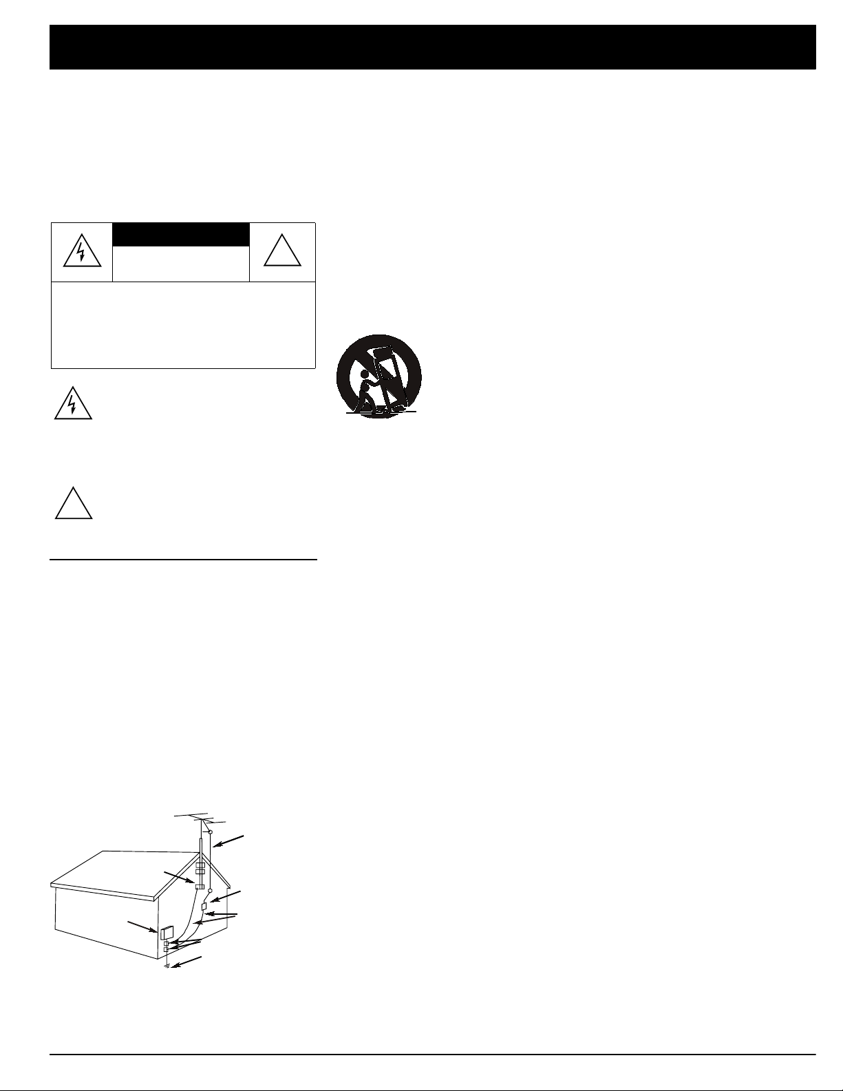
Positioning Speakers
a
L
Halfway Point
Halfway Point
Between Speak
b
b
Normal Listening Point
Person in Listening Area
• Surround speakers generally sound
best if you position them above ear
level.
• To avoid interference with the picture
on a nearby TV, use magnetically
shielded speaker systems. This is particularly important for the center
speaker since it is usually located
closest to the TV.
Between Speakers
a=b
R
a = b
Where you place your speakers (not supplied) can make a noticeable difference
in your system’s sound. The guidelines in this section will help you choose the
best locations. After you use your receiver for a while, you might want to try different locations for your speakers.
Bass response depends largely on speaker location. For strong bass, place the
speakers in the corners of the room. If you want even stronger bass, place the
speakers directly on the floor. If the bass is too strong, move the speakers
slightly away from the corners of the room, or raise them 6 to 18 inches off the
floor. You can buy speaker stands at your local RadioShack store.
The distance between the speakers should be about the same as the distance
between the normal listening point and the point halfway between the speakers.
If you place the speakers too close together, you reduce the stereo separation.
If you place them too far apart, you reduce the bass effect and create a “hole” i n
the middle of the sound.
Most speakers have a tweeter dispersion angle of about 60 degrees. Ideally ,
your listening position should be just inside the overlap area of tweeter dispersion. You can angle the speakers toward you for better stereo effect.
To position your speakers for surround sound, place the A or B (front) speakers
at the front of your listening area, and place the surround (rear) speakers behind
or to the sides of the listening point (see “Using Advanced Sound Options” on
Page 21). Also, place the center speaker above, below, or behind the TV.
Sound might not appear to coincide with the picture if you place it beside the TV
TV
Front Left
Speaker
Rear Left
Speaker
Center Speaker
Listening
Front
Area
Rear
Front Right
Speaker
Rear Right
Speaker
Page 6
Preparing Your Receiver
Wire Strands
Wire Strands
Conductor
Conductor
onnecting Speakers
Follow these guidelines when you select
and connect speakers.
• Be sure you properly connect all
speakers.
• Do n ot connect t wo pairs of speakers
to a single set of terminals (A or B) at
the same time. When you use two
pairs of speakers, conne ct one set to
Speakers A
B
.
and one set to
• Realistic, Optimus, and other highquality speakers have color-coded
speaker terminals (red for positive polarity and black for negative polarity).
Use these color-coded terminals as a
guide to help you properly connect the
speakers to the receiver.
• Us e 16-gauge (or larger) speaker wire
for all speaker connections, and consider possible speaker locations before you decide how much speaker
wire you need.
Speakers
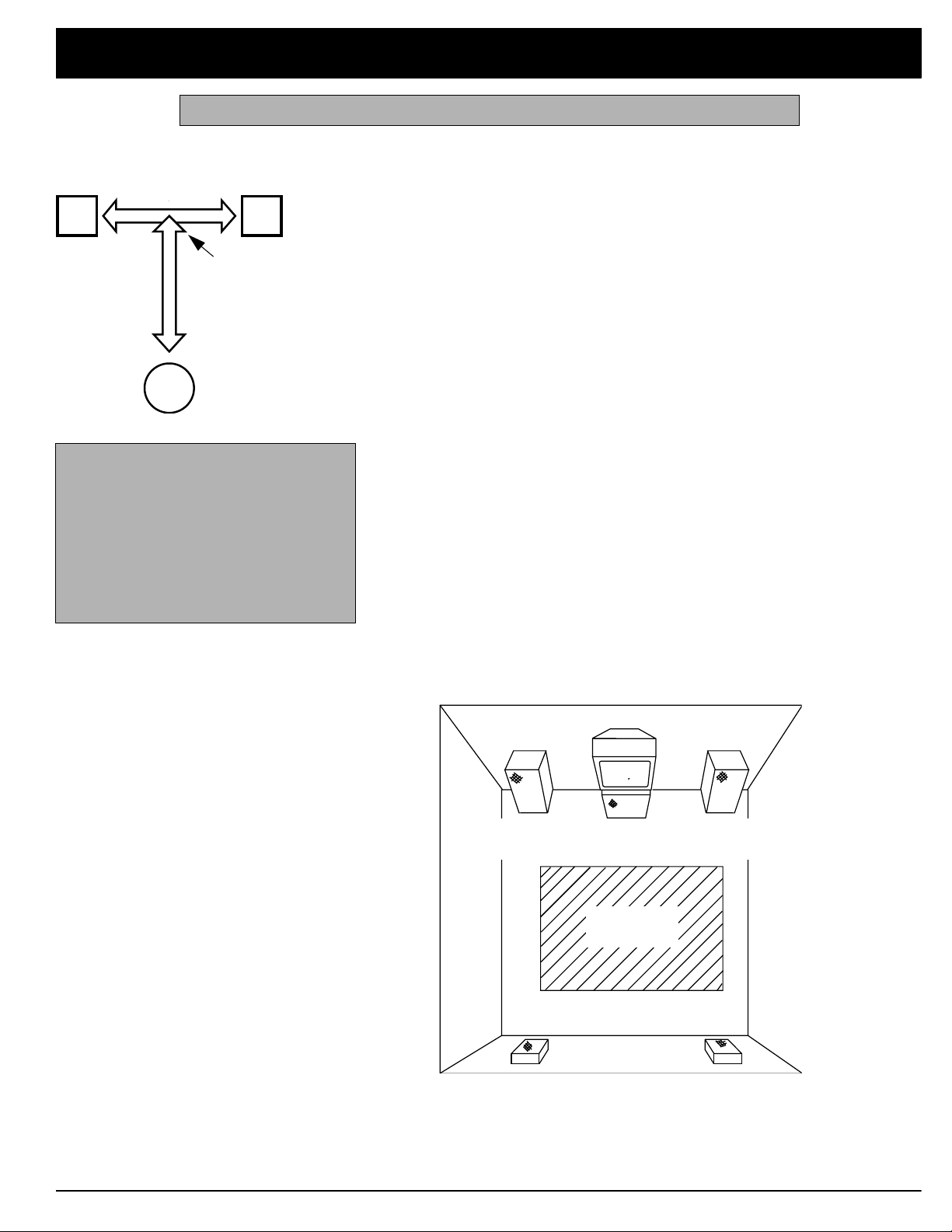
Preparing the Speaker Wires
Speaker wire consists of two conductors (individual wires) encased in insulation
and is usually color-coded or marked with a ridge along one side so you can
identify each conductor. Use these markings as a guide to help you properly
connect the speakers to your receiver.
Follow these steps to prepare the speaker wires.
1. Cut the speaker wires to the necessary length.
2. Separate the wires about 4 inches on each end.
3. Using a wire stripper, carefully strip about
end of each conductor.
3
/4 inch of insulation from the
4. Twist the end of each exposed wire to secure any loose strands.
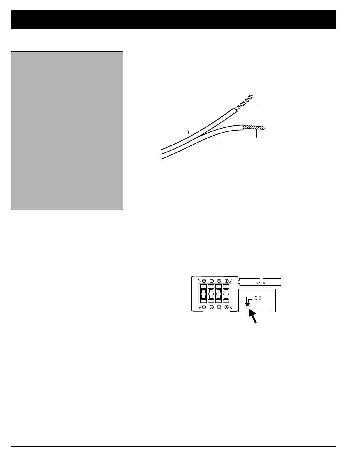
Setting the Impedance Selector Switch
Before connecting speakers, check your speaker system’s impedance (see
IMPED-
your speaker system’s specifications). Normally it is 8W. If it is, leave the
ANCE SELECTOR
switch set to
impedance, set the switch to
8W~16W/ SPEAKER
6Ω~16Ω/SPEAKER
L
R
A
B
R L
.
CAUTION:
A
CAUTION: SEE INSTRUCT MANUAL
B
. If your speaker system has 6W
SPEAKER IMPEADANCE
816
/SPEAKER
/SPEAKER
6 16
8 16
/SPEAKER
IMPEDANCE
Page 7
7
-
-
A
B
A
B
R
L
R L
FRONT SPEAKERS
L
R
PRE OUT
SUB
WOOFER
CENTER
SPEAKER
REAR
SPEAKERS
L
R
AUDIO
IN
PRE OUT
CENTER
AUDIO
IN
Center Channel
Power Amplifier
Amplified
Subwoofer
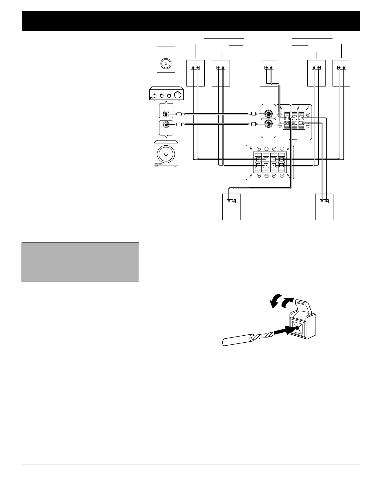
Preparing Your Receiver
Right Front S peakers A Left
Right Front Speakers B Left
Center Speaker
Note:
Be sure you connect the
receiver’s right and left positive (+) and
negative (–) terminals to the speaker’s
corresponding right and left positive (+)
and negative (–) terminals.
Surround
Speakers
LeftRight
Connecting the A and B Speakers
Follow these steps to connect the right speaker to the receiver’s right
SPEAKERS A
1. Lift the receiver’s
2. Lift the receiver’s
terminals.
FRONT SPEAKERS A R
(+) red lever and insert the ridged
or color-coded conductor’s end into the small hole. Pull down the lever to
secure the conductor .
FRONT SPEAKERS A R (–
) black lever and insert the other
conductor’s end into the small hole. Pull down the lever to secure the con
ductor.
FRONT
3. Connect the ridged or color-coded conductor’s loose end to the right
speaker’s positive (+) terminal.
4. Connect the remaining loose conductor to the right speaker’s negative (–)
terminal.
Repeat Steps 1–4 to connect the left speaker to the receiver’s left
terminals.
ERS A
FRONT SPEAK
Repeat this entire process to connect a second pair of speakers to the
SPEAKERS B
terminals.
FRONT
Page 8

Preparing Your Receiver
Connecting Su rround-Sound Speakers
You can connect a pair of speakers to the receiver for surround-sound programs. Follow the steps in “Connecting the A and B Speakers” to connect the
speakers to the
REAR SPEAKERS
terminals.
Connecting the Center Speaker
The center speaker gives additional ambience to surround sound. Connect the
center speaker to the
ing the A and B Speakers.”
CENTER SPEAKER
terminals. Follow the steps in “Connect-
Connecting Center Channel and Subwoofer Amplifiers
To increase th e center channel’s output power, you can connect an amplifier to
the
CENTER PRE OUT
plifier.
Y our receiver includes a line-level subwoofer output. Connecting a subwoofer to
your system dramatically extends bass response for incredible richness and
depth. When you listen to surround-sound programs, a subwoofer enhances
your home theater experience by realistically recreating the rumble of an earthquake, the bone-jarring percussion of a cannon, and more. To use the subwoofer output, simply connect
level input or to an amplifier to which you have connected a subwoofer.
jack. Then connect the center channel speaker to the am-
SUBWOOFER PRE OUT
to an amplified subwoofer’s line-
RadioShack stores sell a variety of suitable subwoofers and amplifiers.
Page 9
9
Preparing Your Receiver
VIDEO
O
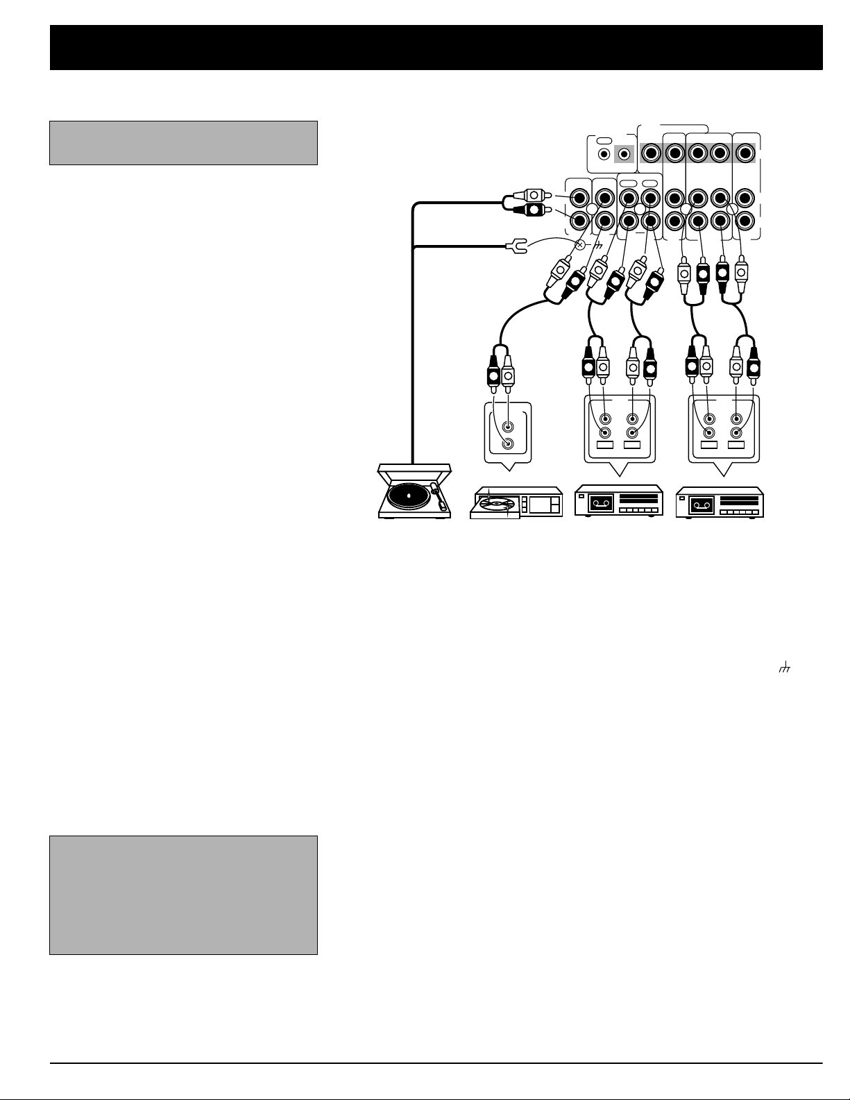
Connecting Program Sources
Use shielded audio cables with phono
connectors for all audio connections.
You can connect up to six external program sources to your receiver.
TO MONITOR TV
IN
IN
PLAY
MONITOR
SIGNAL GND
R
LINE
RECPLAY
L
R
REC
INPUTOUTPUT
TAPE2
L
OUT
OUT
REC
L
IN
IN
IN
LD/
SAT
TAPE 1
L
R
R
R
VCR/
R
L
PLAY
LINE
INOUT
DVD/
TV
R
L
L
RECPLAY
L
R
REC
INPUTOUTPUT
R
OUT PUT
CONTROL
OUT
IN OUTIN IN
L
R
L
PHONO
R
IN
CD
L
R
L
PLAY
L
R
L
L
R
VIDE
L
R
R
Note:
If you place the cassette deck
directly above, below, or to the left of the
receiver, the receiver could interfere with
the cassette deck’s operation. If possible, position the cassette deck to the
right of the receiver or locate it away
from the receiver.
CD
Turntable CD Player Cassette Deck Cassette Deck
Connecting a Turntable
Connect a turntable with a magnetic cartridge only. Some older turntables use a
ceramic-type cartridge that does not work with this system.
Connect the turntable’s left and right cables to the receiver’s left and right
PHONO
jacks. Then connect the turntable’s ground wire to the receiver’s
NAL GND
Connecting a CD Player
terminal.
SIG-
To connect a CD player to the receiver, connect the CD player’s left and right
output jacks to the receiver’s
CD
jacks.
Connecting Cassette Decks
Y ou can connect cassette decks to the
Connect the cassette deck’s output jacks to the
PLAY
jacks, and connect the cassette deck’s input jacks to
dio) or
TAPE 2 OUT REC
jacks.
VCR/TAPE 1
VCR/TAPE 1 IN
and the
You can connect a third cassette deck (for playback only) to the
dio) jacks.
TAPE 2 MONITOR
(audio) or
TAPE 2 IN
VCR/TAPE 1 OUT
LD/SAT IN
jacks.
(au-
(au-
Page 10
Preparing Your Receiver
VIDEO
TO MONITOR TV
IN
IN
PLAY
OUT
REC
OUT
CONTROL
OUT
IN OUTIN IN
v
IN
L
IN
IN
IN
INOUT
VIDEO
L
R
CD
PHONO
SIGNAL GND
v
L
R
V
R
L
V
AUDIO
VIDEO
OUT
VIDEO
IN
OUT
L
R
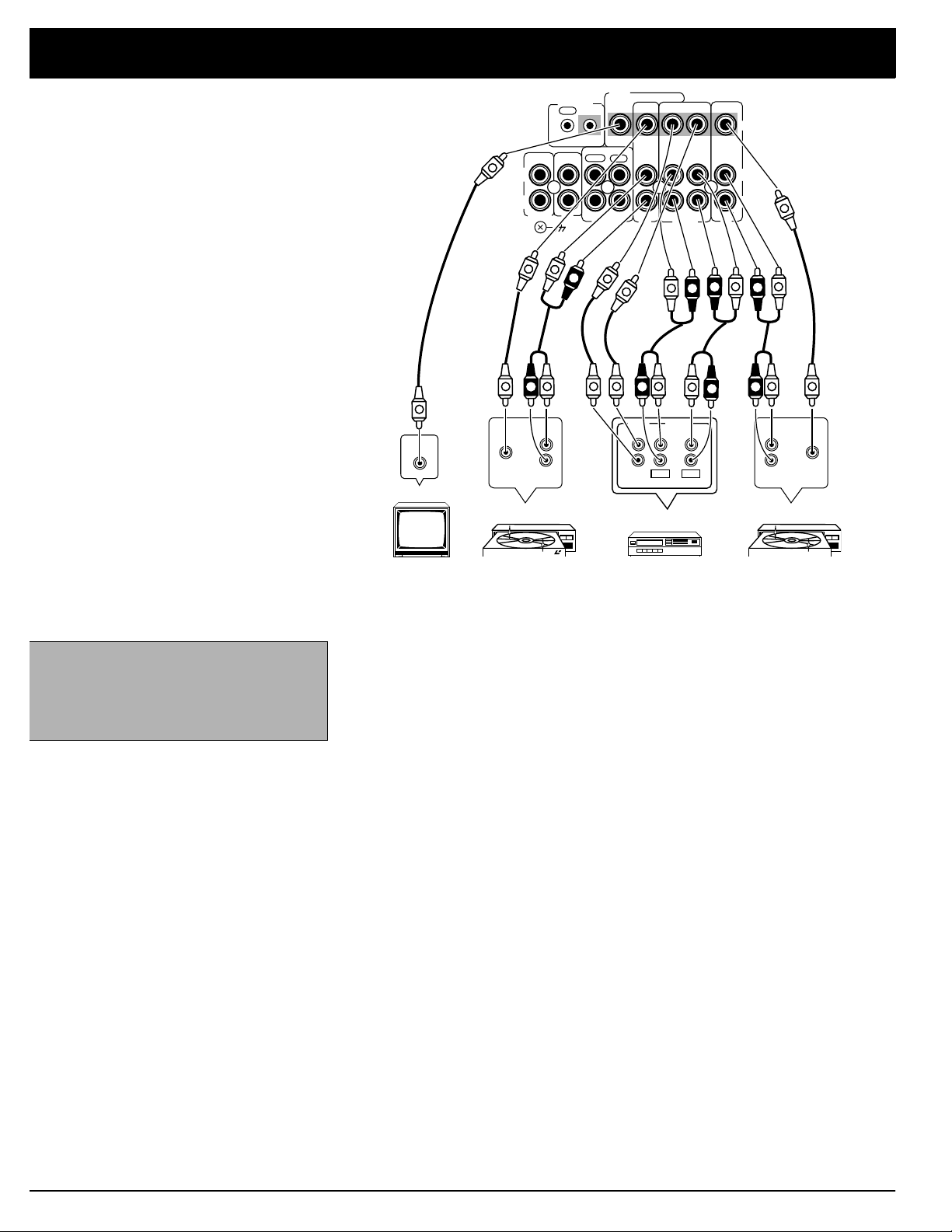
TV Monitor LD Player LD PlayerVCR
Connecting Video Sources
TAPE2
MONITOR
V
V
R
R
R
L
AUDIO
OUT
v
L
V
VIDEO
OUT
L
R
VCR/
TAPE 1
L
R
INPUTOUTPUT
VCR
RECPLAY
REC
DVD/
TV
R
L
R
L
R
LD/
SAT
L
V
R
V
L
AUDIO
VIDEO
IN
OUT
PLAY
Note:
If your VCR is monaural, use a Yadapter (available at your local RadioShack store) to connect the VCR’s
audio output to both the
and R audio in-
L
puts on the receiver.
If you connect two or more video sources, such as VCRs or laser disc players,
to your receiver, you can use the receiver to select each video source. You can
also use the receiver to easily record from the video sources to the source connected to
VCR/TAPE 1
.
Connect phono cables from each video source’s audio outputs to the receiver’s
VCR/TAPE 1
ceiver’s
VCR/TAPE 1 OUT
or
LD/SAT IN
(audio) jacks. Then connect phono cables from the re-
(audio) jacks to the source’s audio input jacks.
Connect video cables from each video source’s video outputs to the receiver’s
VCR/TAPE 1 VIDEO IN
receiver’s
VCR/TAPE 1 VIDEO OUT
or
LD/SAT VIDEO IN
You can connect a third video source to the
source’s video output to the receiver’s
dio outputs to the receiver’s
The front panel
VIDEO L AUDIO R
DVD/TV IN
jacks. Then connect video cables from the
jack to the VCR’s video input.
DVD/TV IN
DVD/TV VIDEO IN
jacks. Connect the
jack, and the source’s au-
(audio) jacks.
jacks accept another audio/video device. These
jacks are convenient for temporarily connecting another video source to the receiver, such as a camcorder.
Connecting a Video Monitor
The monitor (or TV with baseband video input) you connect to the
minal can monitor any program you connect to the receiver’s
or
MONITOR TV
input jacks. Connect a video cable from the receiver’s
DVD/TV
jack to the monitor’s video input.
VCR/TAPE 1, LD/SAT
VIDEO OUT
VIDEO OUT TO
ter-
,
10
Page 11
Preparing Your Receiver
-
-
FM
UNBAL
AM
LOOP
ANTENNA
75
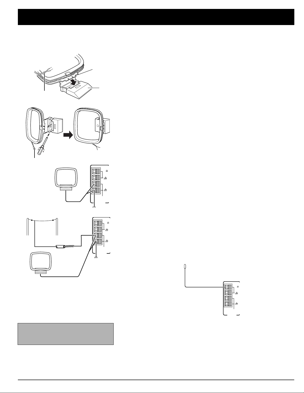
Connecting the Antennas
Antenna
Tabs
Antenna Wires
Antenna Wires
AM Loop Antenna
Base
FM
UNBAL
75
AM
In many areas, the supplied indoor AM loop and FM antennas provide satisfactory reception.
AM Antennas
Assemble the included antenna’s base by swinging the base in the direction of
the arrow and inserting the antenna’s bottom tabs into the base’s slot. Then attach the antenna wires to the
Place the antenna on a flat surface and rotate it for the best AM reception.
If the receiver is in a rack or on a shelf and there is no room for the AM loop an
tenna, use two screws (not supplied) to mount the base on the wall or another
location as shown.
Notes:
• Keep the AM loop antenna connected even when you use another indoor
antenna or an outdoor AM antenna.
• Ensure the antenna does not touch the receiver or other metal objects.
• Do not place the antenna near a CD player, a personal computer, or a TV
set.
• If the wire between your AM loop antenna and receiver is too short, you
can add extra wire, available at your local RadioShack store.
LOOP ANTENNA
terminals (bottom two terminals).
LOOP
ANTENNA
ANTENNA
Ground
Outdoor AM Antenna
AM Loop Antenna
Note:
For the best results, use 75-ohm
ANTENNA
Ground
LOOP
ANTENNA
coaxial cable to connect an outdoor
antenna to the receiver.
FM
UNBAL
75
AM
You can also use a RadioShack shortwave antenna kit (Cat. No. 278-758),
which makes an excellent outdoor AM antenna. Connect the outdoor AM anten
na wire to the receiver’s AM terminal, as shown.
FM Antennas
Connect the supplied FM antenna to the
FM UNBAL 75
extend it.
FM Antenna
For better FM reception, you can also use a rabbit-ear TV antenna (for indoor
use only). To connect the TV antenna to the receiver, you need a VHF/UHF/FM
splitter (not included). RadioShack stores carry a full line of quality antennas
and antenna connection accessories.
Ω
terminal as shown, then
11
Page 12

Preparing Your Receiver
75Ω Coaxial Cable
Center Wire
Shielding
Warning:
To prevent injury, read and follow all cautions and warnings that
accompany the outdoor antenna.
Caution:
only touch the
The cable’s shielding should
GND
termi n al.
For the best radio reception, use an outdoor antenna. Follow these steps to
connect an outdoor FM antenna to the receiver using 75Ω coaxial cable.
Note: If your antenna has 300Ω twin-lead cable, consult your local RadioShack
store for the correct adapter.
1. Disconnect the supplied FM antenna from the receiver’s
FM UNBAL 75
Ω
terminal.
2. With a stripping tool, remove about 1
1
/2 inches of the outdoor antenna ca-
ble’s outer insulation to expose the cable’s shielding.
3. Fold back the outer insulation from the inner insulation.
4. Remove about 1 inch of the inner insulation from around the center wire.
Inner Insulation
Outer Insulation
Shielding
5. Pull the shielding to one side. Connect the center wire to the receiver’s
UNBAL 75
Ω
terminal. Twist the shielding to secure any loose wire strands,
Center Wire
FM
and connect it to the terminal.
FM
UNBAL
75
AM
LOOP
ANTENNA
Note: Grounding is not necessary for reception, but we recommend it to avoid
damage from lightning when you use an outdoor FM antenna and for better FM
reception. Use a separate piece of thick polyvinyl insulated wire to connect the
terminal to the building’s power grounding electrode system.
Warning: Never con nect a wire to a gas pipe for grounding since sparks might
ignite the gas.
12
Page 13

3
Preparing Your Receiver
Using One Remote Control
for More than One Unit
Note:
component’s
ponent’s remote sensor does not function.
When you plug the cable into a
CONTROL
OUT
IN
Receiver
Remote
Control
CONTROL IN
jack, that com-
CONTROL
IN
OUT
Other Component
with OSR Mark
To the CONTROL IN Jack
of Another Component
Having the OSR Mark
If you also have an Optimus professional series CD player, VCR, or cassette
deck with the OSR mark ( ), you can connect its
CONTROL IN
jack to the
receiver so you can control all of your equipment with a single remote control.
You can also use the other component’s remote control by pointing it at the
receiver’s front panel.
1. Connect each component to the receiver as shown in “Connecting Program Sources” on Page 8.
Note:
You must connect the audio cables between the receiver and the
other audio accessory to use your receiver’s remote control to control the
accessory.
2. Connect the cable supplied with the CD player, VCR, or cassette deck to
the receiver’s
CONTROL OUT
jack and the other component’s
CONTROL IN
jack.
3. When you want to control more than one other component using the receiver’s remote control, daisy-chain the
CONTROL OUT
and
CONTROL IN
connections as shown.
Installing the
Remote Control’s Batteries
Cautions:
• Us e only fresh batteries of the recommended size and type.
• Do not mix old and new batteries, different types of batteries (standard,
alkaline, or rechargeable), or rechargeable batteries of different capacities.
• Alway s remove old or weak batteries.
Batteries can leak chemicals that can
damage electronic circuits.
Note:
If the remote’s range is reduced,
replace the batteries.
The remote control uses two AAA batteries (not included). For the longest battery life, we recommend alkaline batteries (RadioShack Cat. No. 23-555).
1. Press and slide open the battery compartment cover.
2. Place two fresh AA batteries in the compartment as indicated by the polarity symbols (+ and –) marked in the compartment. Then replace the
battery compartment cover.
1
Page 14

Preparing Your Receiver
L
R
PRE OUT
SUB
WOOFER
CENTER
SPEAKER
REAR
SPEAKERS
L
R
A
B
A
B
R
L
R L
FRONT SPEAKERS
CAUTION:
DO NOT CONNECT
TV SET OR MONITOR.
AC 120V 60HZ
SWITCHED
100W MAX
0.8A MAX
CAUTION:
SEE INSTRUCT MANUAL
6 16
8 16
/SPEAKER
/SPEAKER
CAUTION:
SPEAKER IMPEADANCE
816
/SPEAKER
IMPEDANCE
SELECTOR
CENTER
PRE OUT
AC OUTLET
MAFUFACTURED UNDER LICENSE FROM DOLBY LABORATORIES
LICENSING CORPOTATION.
"DOLBY" , "PRO LOGIC" AND THE DOUBLE • D SYMBOL ARE
TRADEMARKS OF DOLBY LABORATORIES LICENSING CORPOTARION.
U
L
R
LISTED
8778
AUDIO EQUIPMENT
E 44688
L
R
PRE OUT
SUB
WOOFER
CENTER
SPEAKER
REAR
SPEAKERS
L
R
A
B
A
B
R
L
R L
FRONT SPEAKERS
CAUTION:
DO NOT CONNECT
TV SET OR MONITOR.
AC 120V 60HZ
SWITCHED
100W MAX
0.8A MAX
CAUTION:
SEE INSTRUCT MANUAL
6 16
8 16
/SPEAKER
/SPEAKER
CAUTION:
SPEAKER IMPEADANCE
816
/SPEAKER
IMPEDANCE
SELECTOR
CENTER
PRE OUT
AC OUTLET
MAFUFACTURED UNDER LICENSE FROM DOLBY LABORATORIES
LICENSING CORPOTATION.
"DOLBY" , "PRO LOGIC" AND THE DOUBLE • D SYMBOL ARE
TRADEMARKS OF DOLBY LABORATORIES LICENSING CORPOTARION.
U
L
R
LISTED
8778
AUDIO EQUIPMENT
E 44688
Using the AC Power Outlet
Caution:
high power consumption, such as a
heater, iron, monitor, or TV, to this AC
outlet. Doing so can cause a risk of overheating and fire, and could damage the
receiver.
Do not connect appliances with
onnecting to AC Power
Warning:
not use this polarized plug with an extension cord, receptacle, or other outlet
unless you can fully inse rt the blades to
prevent blade exposure.
To prevent electric shock, do
Your receiver has an AC power outlet that you can use to power another electronic device, such as a turntable, cassette deck, VCR, or so on. This switched
outlet turns on and off with the receiver and provides a maximum of 100 Watts.
Before you plug in the receiver’s power cord, double check all other connections.
To power the receiver, plug the supplied power cord into a standard AC outlet.
The power cord’s plug is polarized and fits only one way.
14
Page 15

5
Basic Op eration
-
-
Warning: To prevent possible hearing
loss, turn
VOLUME
on the receiver or change the program
sources. After you turn on the receiver or
change the program source, adj ust
UME
to a comfortable listening level.
to
MIN
befo re you tu rn
VOL-
The controls on the remote control work the same as the buttons on the
Note:
receiver’s front panel, though some are labeled differently.
Follow these steps to use the receiver.
1. Press
POWER
to turn on the receiver’s power. It takes about 5 seconds to
begin hearing sound.
Note: If you want to find out what a particular button or control is used for, see
Page 23 (for the remote control) or P age
32 (for the fron t panel) to find the page
where the button or control is described.
Note: If you select an other source while
TAPE 2 MONITOR
is selected,
TAPE 2
flashes on the display, reminding you to
disengage the
TAPE 2 MONITOR
function.
2. Select the speakers.
SPEAKERS B
when
A
appears when
is selecte d .
If you connected speakers only to the
SPEAKERS A
press
(or B) to turn on only those speakers.
If you connected speakers to both the
SPEAKERS A
FRONT SPEAKERS A
FRONT SPEAKERS A
is selected. B appears
(or B) terminals,
and
B terminals,
either:
•Press in
SPEAKERS A
or B to turn on either pair of speakers for a two-
speaker stereo effect.
•Press in
SPEAKERS A
and
B to turn on both pairs of speakers for a
four-speaker stereo effect.
Press
SPEAKERS A
and B to turn off the front speakers so you can listen
privately with headphones.
See “Using Advanced Sound Options” on Page 21 for selecting the rear
and center speakers.
3. Select a program source.
To tune to a radio station, see “Tuning the Radio” on Page 17.
To listen to signals from the component connected to
TAPE 2 MONITOR
press
so
TAPE 2
appears on the display.
To listen to a source other than one connected to
TAPE 2
TOR
TUNER, PHONO
does not show on the display. If necessary, press
so
TAPE 2
disappears. Then press
, or repeatedly press
VCR/TAPE 1, LD/SAT, DVD/TV, CD
FUNCTION
on the remote control to dis
TAPE 2 MONITOR
TAPE 2 MONITOR
TAPE 2 MONI-
play the desired program source.
,
be sure
,
,
To view/listen to the source connected to the front panel
jacks, press
press the remote control’s
VIDE O I N PU T
next to the jacks on the front panel, or repeatedly
FUNCTION
button so
VIDEO
appears on the dis
VIDEO L AUDIO R
play .
4. Adjust
decrease it. Or, you can use
5. Use the
6. Adjust
VOLUME
BASS
and
BALANCE
clockwise to increase the volume or counterclockwise to
TREBLE
MASTER VOLUME –/+
controls to adjust the program’s tonal quality.
on the remote control.
to suit your listening preferences. See “Balance Control”
on Page 16.
7. When you finish using the receiver, press
POWER
to turn it off.
1
Page 16

Basic Oper ati on
Balance Control
BALANCE
The
control lets you adjust the sound balance between the left and
right speakers. If you properly position the speakers and your listening area is
centered between them, the center control setting is usually best (see “Positioning Speakers” on Page 5).
Loudness Contro l
Muting the Receiver
Using Headphones
For an unusual speaker placement, adjust
1. Select
2. Press
TUNER
. Then press
FM MONO
so
MONO
FM/AM
appears. The sound is monaural instead of ste-
BALANCE
as follows:
to select the FM band.
reo, so each speaker delivers the same output.
3. Turn
BALANCE
until you hear the sound coming equally from each speaker
when you are in the listening area.
4. Press
FM MONO
so
MONO
disappears from the display.
To increase the high and low ranges of sounds for improved audio at a low listening level, press
appears. Press
LOUDNESS
LOUDNESS
(or
To tempo rarily mute the sound, pres s
appears. Press
MUTING
again to restore the audio level.
LOUD.
(or
LOUD.
on the remote control) so
) again to turn off this feature.
MUTING
on the remote control.
LOUDNESS
MUTING
To listen with headphone s (not supplied), insert the headphones’ 1/4-inch plug
into the receiver’s front panel
listen with headphones without disturbing others, press
PHONES
jack. To silence the speakers so you can
SPEAKERS A
and B.
Listening Safely
To protect your hearing, note the following when using headphones.
• Set the volume to its lowest setting before you begin listening. After you
begin listening, adjust the volume to a comfortable level.
• Do not listen at extremely high volume levels. Extended highvolume listening can lead to permanent hearing loss.
• Once you set the volume, do not increase it. Over time, your ears adapt to
the volume level, so a volume level that does not cause discomfort might
still damage your hearing.
16
Page 17

7
Basic Operation
-
-
-
-
Tuning the Radio
You can tune your receiver manually or you can store stations in memory.
Manual Tuning (Front Panel Only)
Follow these steps to manually tune to a station.
1. Press
TUNER
. Then press
FM/AM
to select the desired band.
When you select the AM or FM band, the receiver tunes to and displays
the frequency last selected in that band.
2. Press
3. Turn
SELECT
MULTI JOG
FREQ
so
appears on the
to tune the desired station.
JOG MODE
TUNED
display.
appears when you
tune to a strong station.
Memory Tuning
Memory tuning lets you store up to 30 AM or FM frequencies in one of three dif
ferent classes (10 frequencies in each class), then you can instantly tune to a
stored station. The three classes let you group stations so there are fewer stations to search through to find the one you want.
Follow these steps to store a station in a memory location.
1. Press
TUNER
. Then press
FM/AM
to select the desired band.
Notes:
• If you store a frequency in a memory
that already contains a freq uency, you
replace the previous frequency.
• If your receiver is disconnected from
AC power for several da ys, it loses all
the stored frequencies.
2. Use manual tuning to select the frequency you want to store.
If desired, press
FM MONO
for FM stereo or monaural sound (see “Using
FM MONO” on Page 18 ). This setting is also stored in the memory.
3. Press
4. While
MEMORY
MEMORY
want appears, turn
then press
MEMORY
.
appears for 5 seconds.
is on the display, press
MULTI JOG
ENTER
to store the frequency in memory.
to select the memory number you want,
CLASS
so the class number you
The frequency and class number flash, then light steadily.
To tune to a stored station, press
play. P ress
CLASS
to select the class number you want, then t urn
SELECT
so ST appears on the
JOG MODE
MULTI JOG
dis
until
the desired frequency appears on the display. When you reach the last frequen
cy in a class, the receiver automatically moves to the next memory class.
You can also use
STATION
on the remote control to select a station in memo
ry. See “Using the Remote Control” on Page 23.
1
Page 18

Basic Oper ati on
Using FM MONO
To receive FM stations in stereo, press
display.
You can improve the reception of weak FM stations by pressing
MONO
you get monaural instead of stereo sound.
STEREO
appears. This reduces noise while you listen to a weak FM station, but
appears when the tuner receives an FM broadcast in stereo.
FM MONO
so
MONO
disappears from the
FM MONO
so
18
Page 19

9
Cassette Deck/VCR Features
-
Using the VCR/TAPE 1 and
TAPE 2 Monitor Buttons
You can connect two cassette decks to the receiver. Selecting either
TAPE 2 MONITOR
or
nected to the receiver’s corresponding (
VCR/TAPE 1
Press
cassette deck or VCR you connected to the receiver’s
TAPE 2 MONITOR
Press
lets you hear the playback from the cassette deck you con-
VCR/TAPE 1, TAPE 2 MONITOR
VCR
.
appears on the display. You hear the playback from the
VCR/TAPE 1
TAPE 2
.
appears on the display along with the last pro-
VCR/TAPE 1
) jacks.
jacks.
gram source you selected. You can hear playback or monitor a recording from
the cassette deck you connected to the receiver ’s
TAPE 2 MONITOR REC
source when you press
To return to the previous source, press
jacks continue to output sound from the previously selected
TAPE 2 MONITOR
.
TAPE 2 MONITOR
TAPE 2 MONITOR
again so
jacks. The
TAPE 2
disa p
pears.
Notes:
• If you press
TAPE 2 MONITOR
when the cassette deck is neither playing nor
recording, the receiver mutes the current audio source. To hear the audio
source, press
• Do not press
nected to
TAPE 2 MONITOR REC
TAPE 2 MONITOR
TAPE 2 MONITOR
TAPE 2
so
disappears from the display.
while you are recording on the deck con-
. If you do, the recording is interrupted for
about 1 second.
Recording an Audio Source
Dubbing a Cassette Tape
The receiver sends the audio of the program source you select—
TAPE 2 MONITOR, DVD/TV, LD/SAT, CD, TUNER, PHONO
OUT
(audio) and
TAPE 2 MONITOR REC
jacks.
, or
VIDEO
VCR/TAPE 1
—to the
VCR/TAPE 1
You can copy, or dub, a cassette tape from one cassette deck to another.
You can use either deck as the playback or recording deck. However, if you
want to monitor the cassette deck during dubbing, use the deck connected to
VCR/TAPE 1
the
jacks as the source, and the deck you connected to the
jacks as the recording deck. Then press
TAPE 2 MONITOR
TAPE 2
so
TAPE 2
appears on
the display to hear the recording. See “Using the VCR/TAPE 1 and TAPE 2
Monitor Buttons.”
Note:
VOLUME, BALANCE
The
, and tone controls do not affect the signal going to
the t ape decks.
,
1
Page 20

Cass ette Deck/VCR Features
Playing and Recording
ideo Tap es
You can connect four video sources to the receiver. If you connect a VCR to the
VCR/TAPE 1
audio and video jacks, you can copy video tapes from one VCR to
another and monitor the dubbing process.
Playing a Video Tape
To play a video tape, load the tape into the VCR connected to either
LD/SAT, or DVD/TV
. Press the button (
sponds to the jack the VCR is connected to.
VCR/TAPE 1, LD/SAT
VCR, LD/SAT
, or
DVD/TV
, or
the display. To view the program on a source connected to the front panel
L AUDIO R
jacks, press
VIDEO INPUT
next to the ja cks.
VIDEO
appears on the display. Follow the VCR’s instructions to begin playback. If you connected a monitor to the receiver’s
VIDEO OUT
jack, you can view the program on that monitor.
VCR/TAPE 1
) that corre-
DVD
appears on
VIDEO
Copying a Video Tape
Follow these steps to copy a video tape from one VCR to another.
1. Load the tape you want to copy into a VCR connected to the
TV
, or front panel
VIDEO L AUDIO R
jacks.
2. Load a blank tape (or one you want to record over) into the VCR connected to the
3. Press
VCR/TAPE 1
LD/SAT, DVD/TV
jacks.
VIDEO INPUT
, or
.
LD/SAT, DVD/
,
4. Begin recording and playback on the VCRs.
Important:
Most material performed in public, such as concerts, plays, and
movies, or distributed on prerecorded video tapes is copyrighted. The unauthorized recording or duplication of copyrighted material is a violation of the copyright laws of most countries and such duplication may result in fines,
imprisonment, or both. Note, however, that in the United States, it is not a violation of U.S. copyright laws for a consumer to record a broadcast television program for private (in-home) viewing.
0
Page 21

Using Advanced Sound Options
-
-
-
Your receiver has three special sound options: Dolby Pro Logic Surround, SFC
Effects, and 5-D Theater. These special options enhance the sound you hear
from a program source.
Notes:
• To get the full benefit from programs encoded with Dolby Surround
Sound, you need a stereo VCR.
• Dolby Surround does not operate correctly if the signal passes through a
graphic equalizer. If you connected an equalizer to the
jacks, do not select
signals.
TAPE 2 MONITOR
TAPE 2 MONITOR
when you listen to Dolby Surround
To activate Dolby Pro Logic Surround, press
the remote control). For Dolby 3CH Logic, repeatedly press the remote control’s
CENTER MODE
or 5 D Theater, press
on the display.
button until
3CHLOGIC
SFC MODE or 5-D THEATER
appears on the display. For SFC effects
DOLBY PRO LOGIC
until the desired option appears
PRO LOGIC
(or
on
Dolby Pro Logic Surround
Dolby Pro Logic Surround puts you in the middle of the action. The center- and
rear-channel speakers add incredible realism by directing the sound to the appropriate speakers, making you feel like you are really there. Y ou can find hundreds of movies, television shows, and compact discs produced with Dolby
Surround.
Dolby 3CH Logic
Dolby 3CH Logic produces a more spacious sound field than is possible with or
dinary stereo playback by combining the front and rear speaker sounds. Select
this mode when you play a Dolby Surround Sound program and do not have
rear speakers. The rear channel’s sound is sent to the front left and right speak
ers.
SFC Effects
You can choose one of four SFC effects—
Hall Effect simulates a large concert hall, best suited for classical music. Jazz
Effect provides the acoustic effects generally heard in jazz clubs. Studio Effect
gives the effect of listening in a recording studio. Arena Effect is ideal for sources such as live performances. Try each setting and find the best effect for the
programs you want to listen.
HALL, JAZZ, STUDIO
, or
ARENA
.
5-D Theater
5-D Theater provides clearer and more dynamic sound effects by outputting au
dio signals through the rear channel to simulate the stereo sound, compared
with a standard surround system which provides only monaural signals to the
rear speakers. Select
5-D SURR.
select
5-D Theater Surround (
Note:
front speakers, enhanced with simulated surround sound from the rear speakers. The center channel does not operate.
5-D PRO
for normal stereo sources.
for sources encoded with Dolby Pro Logic, or
5-D SURR.
) produces stereo sound from the
21
Page 22

Using Ad vanced Sound Options
ound Mode Adjustments
Remote Control Only)
Note:
If you do not use a center speaker,
the monaural signals are only reproduce d if you se lect PHANTOM.
Center Mode Setting
The center mode setting affects the center channel’s bass signals. It operates
only when you select Dolby Pro Logic Surround Sound. Each time you press
CENTER MODE
NORMAL, WIDE, PHANTOM
plays:
NORMAL
and right speakers play the center-channel bass sounds.
WIDE
— Select this mode if you use a medium or large center speaker. The
center speaker plays the center-channel bass sounds.
PHANTOM
nel sound is sent to the front left and right speakers.
3CHLOGIC
channel’s sound is sent to the front left and right speakers.
on the remote control, the setting changes and the receiver dis-
3CHLOGI C
, or
— Select this mode if you use a small center speaker. The front left
— Select this mode if you have no center speaker. All center-chan-
— Select this mode if you do not have rear speakers. The rear
.
Test Tone
This feature provides a test tone that lets you balance the signal levels between
all your speakers. See “Center Level” and “Rear Level.”
To activa te the test tone, select one of the surround sound modes and set
DIO/VIDEO
sounds a 2-second tone from the front left, center, front right, and rear speakers,
in sequence.
on the remote control to
AUDIO
. Then press
TEST TONE
. The receiver
AU-
Note:
Use the
VOLUME
the overall sound level.
con trol t o adjus t
Notes:
• The center test tone sounds only when you select the Dolby Pro Logic
Surround (except PHANTOM) or 5-D Pro Logic sound mode.
• In the Dolby 3CH Logic sound mode, the receiver sounds a 2-second
tone from the left, center, and right speakers, in sequence.
TEST TONE
Press
again to turn off this feature.
Center/Rear Leve ls
CENTER LEVEL –/+
Press
REAR LEVEL –/+
Press
CENTER LEVEL
Both
ports the center or rear speakers. For example,
Dolby 3CH Logic.
to adjust the center speaker sound level.
to adjust the rear speakers’ sound level.
REAR LEVEL
and
work only for the sound system that sup-
REAR LEVEL
does not work for
2
Page 23

3
Using the Remote Control
g
g
g
g
g
g
g
g
.
g
g
g
g
g
g
g
g
g
The remote control works up to a distance of about 23 feet, and within a 30-degree angle on either side of the receiver. Point the control at the receiver’s front
panel and press the desired button(s).
Many buttons on the remote control work the same as buttons on the receiver’s
front panel. Use these buttons exactly as you would use the corresponding buttons on the receiver.
AUDIO/VIDEO Switch
The remote control can also control other compatible audio/video compo nent s
when you connect them to the receiver’s
Remote Control for More than One Unit” on Page 13.) Set
to control audio components such as CD players or cassette decks. Set the
switch to
CONTROL OUT
VIDEO
to control video components such as a VCR.
jack. (See “Using One
AUDIO/VIDEO
to
AUDIO
TRANSMIT/LEARN
LEARN RESET
RECEIVER
POWER
FUNCTION
TAPE 2
MONITOR
CENTER LEVEL REAR LEVEL
1234
5678
9
TV
POWER
ASMS
CD
POWER
BEST RANDOM
CD
DISC
MUTING
PRO
ROGIC
LOUD.
0/10
FM/AM
TV MODE
TUNER/TV
AUDIO VIDEO
MASTER VOLUME
SFC
THEATER
MODE
CENTER
MODE
STATION
TV CHANNEL
CLASS FM MONO
– TV VOLUME +
DECK 1 DECK 2
– VCR CH +
ASMS
TAPE/VCR
TAPE/VCR
TEST
TONE
POWER
When you set the switch to
marked in gold next to the button. For example, the button marked
MODE
operates as the radio band switch when you select
mode switch when you select
VIDEO
, dual-function buttons control the function
AUDIO
VIDEO
.
FM/AM
and
TV
and as the TV
Receiver/Amplifier Operation
RECEIVER POWER
MUTING
MASTER VOLUME – /+
FUNCTION
5-D
Receiver/
Amplifier
Section
PRO LOGIC
SFC MODE
5-D THEATER
TAPE 2 MONITOR
LOUD.
CENTER MODE
TEST TONE
Turns the receiver on and off. See Pa
Silences the receiver. Press a
previous level. See Pa
ain to restore the sound to its
e 16.
Adjusts the system’s volume. See Pa
Selects a pro
ram source (VCR/Tape 1, DVD/TV, LD/SAT,
CD, tuner, phono, or video). Repeatedly press
until the display shows your desired pro
Pa
e 15.
Turns the Dolby Pro Lo
ic Surround o n and off. See Page 21
e 15.
e 14.
FUNCTION
ram source. See
Selects between the Hall, Jazz, Studio, or Arena Ef fects, or
turns the SFC Mode off. See Pa
Selects between 5-D Pr o Lo
5-D function off. See Pa
e 21.
e 21.
ic or 5-D Surround, or t urns the
Switches the receiver to monitor the source connecte d to the
TAPE 2 MONITOR
Boosts/cuts hi
levels. See Pa
Selects amon
Sounds test tones from each speaker. See Pa
jacks. See Page 19.
h and low frequency sounds at low l istening
e 16.
the four center mode settings. See Page 22.
e 22.
STAV-3890
AUDIO/VIDEO PROGRAMMABLE
SYSTEM REMOTE
CENTER LEVEL – /+
REAR LEVEL – /+
Controls the relative vol ume of the center spea ker. See Pa
22.
Controls the relative volume of the rear speakers. See Pa
e
e
22.
2
Page 24

Using the Remote Control
g
g
g
g
g
g
g
g
g
g
g
Tuner/TV Operation
TRANSMIT/LEARN
LEARN RESET
RECEIVER
POWER
FUNCTION
TAPE 2
MONITOR
CENTER LEVEL REAR LEVEL
1234
5678
9
TV
POWER
ASMS
CD
POWER
BEST RANDOM
AUDIO/VIDEO PROGRAMMABLE
MUTING
PRO
ROGIC
LOUD.
TUNER/TV
0/10
FM/AM
TV MODE
CD
DISC
STAV-3890
SYSTEM REMOTE
AUDIO VIDEO
MASTER VOLUME
SFC
THEATER
MODE
CENTER
MODE
STATION
TV CHANNEL
CLASS FM MONO
– TV VOLUME +
DECK 1 DECK 2
– VCR CH +
ASMS
TAPE/VCR
TAPE/VCR
TEST
TONE
POWER
For these functions, set
AUDIO/VIDEO
to
to control the tuner, or to
AUDIO
VIDEO
to
control a TV. You must train the remote control for TV functions (see “Training
the Remote Control” on Page 25).
1– 9, 0/10
STATION
– TV CHANNEL +
TV POWER
FM/AM
TV MODE
5-D
CLASS
FM MONO
Tuner/TV
Section
– TV VOLUME +
Press to sele ct memory locat ions in the tune r mode. Press to
directly enter t he channel number in the direct tuni n
See Pa
Tunes to the next hi
AUDIO/VIDEO
Tunes to the next hi
VIDEO
Turns the TV on and off with
Selects the tuner band with
Pa
Selects the TV’s mode with
set to
e 17.
e 17.
set to
VIDEO
her or lower memory location with
AUDIO
. See Page 17.
her or lower TV channel with
.
AUDIO/VIDEO
AUDIO/VIDEO
AUDIO/VIDEO
set to
set to
set to
mode.
AUDIO
VIDEO
AUDIO
VIDEO
/
.
. See
(for
TVs with multiple modes, such as CATV/Tuner).
Selects the memory class with
See Pa
e 17.
AUDIO/VIDEO
Selects the FM reception mode with
AUDIO
. See Page 18.
Adjusts the TV’s volume with
AUDIO/VIDEO
AUDIO/VIDEO
set to
set to
AUDIO
set to
VIDEO
.
.
CD Player Operation
CD Player
Section
Before operation:
•Press
CD POWER
to select the CD player operation.
• You must connect the CD player to both your receiver’s
audio jacks for these functions to work.
ASMS | / |
Returns to the be
inning of the cur rent track/chapter or ad-
vances to the next tra ck/chapter.
CONTROL OUT
and
Plays the CD. Durin
play, pressing this button pauses play-
back.
DISC
CD POWER
Selects discs in a multi-play CD chan
Note: DISC
does not work with all CD players .
er.
Turns the CD player on and off (only for CD players havin
CONTROL IN/OUT
the
feature).
Stops playback.
BEST
Selects your favorite pro
CD, press
BEST
. The unit memorizes the track number then
rams. During play of your favorite
plays only the memorized tracks later (when you press
BEST
while play is stopped) .
RANDOM
Plays the tracks on a CD in random order.
4
Page 25

5
Tape/VCR Operation
-
g
g
Before operation:
Using the Remote Control
TRANSMIT/LEARN
LEARN RESET
RECEIVER
POWER
FUNCTION
TAPE 2
MONITOR
CENTER LEVEL REAR LEVEL
1234
5678
9
TV
POWER
CD
POWER
BEST RANDOM
AUDIO/VIDEO PROGRAMMABLE
MUTING
PRO
ROGIC
LOUD.
TUNER/TV
0/10
FM/AM
TV MODE
ASMS
CD
DISC
STAV-3890
SYSTEM REMOTE
AUDIO VIDEO
MASTER VOLUME
SFC
THEATER
MODE
CENTER
MODE
STATION
TV CHANNEL
CLASS FM MONO
– TV VOLUME +
DECK 1 DECK 2
– VCR CH +
ASMS
TAPE/VCR
TAPE/VCR
TEST
TONE
POWER
•Set
AUDIO/VIDEO
to
• For a cassette deck, select
• For a dual cassette deck, select
5-D
sette deck, press
DECK 2
• You must connect the tape deck/VCR to both your receiver’s
and audio jacks for these functions to work.
OUT
DECK 1/DECK 2
– VCR CH +
Tape/VCR
Section
ASMS /
for a cassette deck or to
AUDIO
TAPE 2 MONITOR
DECK 1
or
or
VCR/TAPE 1
. If you use a single cas
DECK 2
VIDEO
for a VCR.
.
.
CONTROL
Selects Deck 1 or Deck 2 when you use a dual cassette deck
AUDIO/VIDEO
with
Moves to the next hi
VIDEO
set to
.
Press to start pl aybac k. Press t o play the ot her si de of an
auto-reverse cassette deck
For a cassette deck, le ts you quickly locat e and play the
be
inning of recorded material during play.
AUDIO
set to
.
her or lower channel wit h
.
AUDIO/VIDEO
When the tape is stopped, let s you rapidly search forwa rd or
backward to locate a spec if ic section of the tape.
For a VCR, lets you rapidly view a tape ei ther forward or
backward.
Stops playback.
Resetting the Remote
Control
Training the Remote Contro l
T APE/VCR POWER
Turns on th e conn ected VCR wi th
turns on the cassette deck with
Note:
TAPE/VCR POWER
does not work with all decks.
AUDIO/VIDEO
AUDIO/VIDEO
set to
set to
VIDEO
AUDIO
.
If the remote control does not function due to strong static electricity, for example, insert a pointed object (such as a straightened paper clip or the tip of a pen)
into th e
hole on the top of the STA V-3690 remote control, then press and
RESET
release it. This resets the remote control.
You can use your STAV-3690’s remote control instead of ones for other audio/
video components. To do this, you must first teach your STAV-3690’s remote
the other device’s remote control commands.
You can program the commands that appear on the remote control buttons. By
changing the position of the
AUDIO/VIDEO
switch, you can program two com-
mands to a single button.
Notes:
• You do not need to turn on the receiver or the other device.
• You might not be able to teach commands from some remotes.
;
2
Page 26

Using the Remote Control
1–2''
Follow these steps to train the STAV-3690’s remote control.
1. Place both controls 1–2 inches apart with the windows facing each other.
2. Select the
AUDIO/VIDEO
best matches the function—to
VIDEO
for a VCR or television.
switch position. Set the switch to the position that
AUDIO
for a CD player or tape deck or to
3. Insert a pointed object (such as a straightened paper clip or the tip of a
LEARN
pen) into the
hole on the STAV -3690’ s remote control, then press
and release. The TRANSMIT/ LEARN indicator flashes.
4. Within 1 minute, press the STAV-3690’s remote button you want to train.
The TRANS M IT/LEARN in dicator lig hts s teadily.
5. Within 1 minute, hold down the other device’s remote control button that
you want the STAV-3690’s remote to learn. The TRANSMIT/ LEARN indicator flashes.
If TRANSMIT/LEARN flashes twice, the signal might be too weak. Place
the remote controls closer together and try again.
If TRANSMIT/LEARN repeatedly flashes, the remote control’s memory is
full. Programming errors can fill memory. For example, fluorescent light,
direct sunlight, the two remote controls being too far apart, or a low battery might cause this error. Correct the error and try again.
6. Repeat Steps 4 and 5 to teach additional commands.
7. To exit the teaching mode, press
To clear all learned commands from mem ory, press
ER
TAPE/VCR POWER
, and
at the same time. The
LEARN
or wait 1 minute.
TRANSMIT/LEARN
RECEIVER POWER, CD POW-
indicator flash-
es four times.
6
Page 27

7
Troubleshooting
If the receiver is not working as it should, the following suggestions might help. If you follow the suggestions in this chart and
the receiver still does not work properly, contact your local RadioShack store for assistance.
Problem Cause Suggestion
Power does not turn on. Power cord is disconnected. Plug in the power cord.
Protection circuit is activated. Unplug the power cord, then plug it in again.
The receiver does not respond
to button presses.
No sound. Incorrect connections. Check and correct the connections.
No picture when you select a
video source.
High noise level. Station not correctly tuned. Tune to a stronger station.
Cannot make copies of video
tapes.
Remote does not control cassette deck or CD player.
Static discharge has affected the receiver.
The mute function is activated. Press
The volume is turned down. Turn up the volume.
Speaker wires are disconnected. Connect the speaker wires.
Neither set of speakers is selected. Press in
TAPE 2 function is engaged. Press
The selected video source is not set
correctly.
Incorrect connections. Correct the connections.
Antenna not connected. Connect the antenna.
FM antenna still coiled or is not point-
ing in the correct direction.
AM loop antenna not pointing in the
correct direction.
Noise is coming from another electri-
cal appliance.
Tapes are protected by a copy protec-
tion method.
Video connections are incorrect. Check and correct the connections.
Cassette deck or CD player not com-
patible.
Control cable is not plugged in. Properly connect the control cable.
Audio cables are not plugged in. Properly connect the audio cables.
Unplug the power cord, then plug it in again.
(If static electricity is a problem, try to use the
remote control whenever possible.)
MUTING
TAPE 2
the display.
Correct the problem with the selected video
source.
Stretch both ends of the antenna taut and reposition the antenna.
Adjust the AM loop antenna.
Try using an AC line noise filter to reduce the
noise.
You cannot make a usable copy.
This feature works only with Optimus Professional Series components.
.
SPEAKERS A
TAPE 2
so
or B.
disappears from
Returning Controls to
Factor y Defaults
RETURN
Press
Tape 2 Monitor Off
Source TUNER
Speakers A On
Band
Surround Mode Off
Muting Off
on the receiver to return the controls to the following settings.
FM or AM (Set to the last-tuned frequency . If the receiver
cannot receive the frequency, it starts searching for the next
strong station.)
2
Page 28

Care and Maintenance
our ST A V -3690 Audio/Video Receiver is an example of superior design and craftsmanship. The following suggestions will help
ou care for the receiver so you can enjoy it for years.
Keep the receiver dry. If it gets wet, wipe it dry immediately. Liquids can contain
minerals that can corrode the electronic circuits.
Handle the receiver gently and carefully. Dropping it can damage its circuit
boards and can cause the receiver to work improperly.
Use and store the receiver only in normal temperature environments. Temperature extremes can shorten the life of electronic devices, damage batteries, and
distort or melt plastic parts.
Keep the receiver away from dust and dirt, which can cause premature wear of
parts.
Wipe the receiver with a damp cloth occasionally to keep it looking new. Do not
use harsh chemicals, cleaning solvents, or strong detergents to clean the receiver.
Use only fresh batteries of the recommended size and type in the remote control. Always remove old or weak batteries. They can leak chemicals that can destroy electronic circuits.
odifying or tampering with your receiver ’s internal components can cause a malfunct ion and might invalidate the receiver’s
arranty and void your FCC authorization to operate it. If the receiver is not operating as it should, take it to your local
adioShack store for assistance.
8
Page 29

9
The FCC Wants You To Know
Your receiver might cause radio or TV interference even when it is operating
properly. To determine whether your receiver is causing the interference, turn off
your receiver. If the interference goes away, your receiver is causing it. Try to
eliminate the interference by:
• Moving your radio or TV away from the receiver
• Connecting your receiver to an outlet that is on a different electrical circuit
from the radio or TV
• Contacting your local RadioShack store for help
If you cannot eliminate the interference, the FCC requires that you stop using
your receiver.
2
Page 30

Specifications
mplifier
ront Channel Average Power Output . . . . . . . . . . . . . . . . . . . . . . . . . . . . . . . . . . . . . . . . . 100 Watts per Channel into 8 Ohms
From 20 to 20,000 Hz,
With No More than 0.09% Total Harmoni c Distortion
Measured Pursuant to the Federal Trade Commission’s
Trade Regulation Rule on Amplifier Output Power Claims
ront Channel Surround Power Output . . . . . . . . . . . . . . . . . . . . . . . . . . . 100 Watts per Channel (1 kHz, 0.8% THD, 8 Ohms)
enter Channel Surround Power Output . . . . . . . . . . . . . . . . . . . . . . . . . . . . . . . . . . . . 100 Watts (1 kHz, 0.8% THD, 8 Ohms)
ontinuous Rear Surround Power Output . . . . . . . . . . . . . . . . . . . . . . . . . . . . . . . . . . . 100 Watts (1 kHz, 0.8% THD, 8 Ohms)
nput Sensitivity/Impedance
Phono . . . . . . . . . . . . . . . . . . . . . . . . . . . . . . . . . . . . . . . . . . . . . . . . . . . . . . . . . . . . . . . . . . . . . . 2.8 mV/47 kOhms
CD, LD, VCR/TAPE 1, Tape 2 Monitor, DVD/TV, Video . . . . . . . . . . . . . . . . . . . . . . . . . . . . . . . 200 mV/47 kOhms
hono Overload Level (0.1% THD, 1 kHz) . . . . . . . . . . . . . . . . . . . . . . . . . . . . . . . . . . . . . . . . . . . . . . . . . . . . . . . . . . . 100 mV
requency Response
Phono . . . . . . . . . . . . . . . . . . . . . . . . . . . . . . . . . . . . . . . . . . . . . . . . . . . . . . . . . . . . . . 2 0 Hz to 20,000 Hz ±0.3 dB
CD, LD, VCR/TAPE 1, TAPE 2 Monitor, DVD/TV, Video . . . . . . . . . . . . . . . . . . . . . . 5 Hz to 100,000 Hz +0/–3 dB
utput Level/Impedance
VCR/TAPE 1 REC, Tape 2 Monitor REC . . . . . . . . . . . . . . . . . . . . . . . . . . . . . . . . . . . . . . . . . . 200 mV/2.2 kOhms
one Controls
Bass . . . . . . . . . . . . . . . . . . . . . . . . . . . . . . . . . . . . . . . . . . . . . . . . . . . . . . . . . . . . . . . . . . . . . . . . . ±9 dB (150 Hz)
Treble . . . . . . . . . . . . . . . . . . . . . . . . . . . . . . . . . . . . . . . . . . . . . . . . . . . . . . . . . . . . . . . . . . . . . . . . ±9 dB (10 kHz)
ignal-to-Noise Ratio (IHF, Short Circuited, A Network)
Phono . . . . . . . . . . . . . . . . . . . . . . . . . . . . . . . . . . . . . . . . . . . . . . . . . . . . . . . . . . . . . . . . . . . . . . . . . . . . . . . 72 dB
CD, LD, VCR/TAPE 1, Tape 2 Monitor, DVD/TV, Video . . . . . . . . . . . . . . . . . . . . . . . . . . . . . . . . . . . . . . . . . 96 dB
ignal-to-Noise Ratio (EIA, at 1 Watt, 1 kHz)
Phono . . . . . . . . . . . . . . . . . . . . . . . . . . . . . . . . . . . . . . . . . . . . . . . . . . . . . . . . . . . . . . . . . . . . . . . . . . . . . . . 75 dB
CD, LD, VCR/TAPE 1, Tape 2 Monitor, DVD/TV, Video . . . . . . . . . . . . . . . . . . . . . . . . . . . . . . . . . . . . . . . . . 79 dB
ideo Section
nput Sensitivity/Impedance VCR/TAPE 1, LD, DVD/TV, Video . . . . . . . . . . . . . . . . . . . . . . . . . . 1 Vo lt Peak-to-Peak/75 Ohms
utput Level/Impedance VCR/TAPE 1, Monitor . . . . . . . . . . . . . . . . . . . . . . . . . . . . . . . . . . . . . 1 Volt Peak-to-Peak/75 Ohms
requency Response VCR/TAPE 1, DVD/TV, Video, LD Monitor . . . . . . . . . . . . . . . . . . . . . . . . . . . . . 5 Hz to 7 MHz +0/–3 dB
ignal-to-Noise Ratio . . . . . . . . . . . . . . . . . . . . . . . . . . . . . . . . . . . . . . . . . . . . . . . . . . . . . . . . . . . . . . . . . . . . . . . . . . . . . 55 dB
rosstalk . . . . . . . . . . . . . . . . . . . . . . . . . . . . . . . . . . . . . . . . . . . . . . . . . . . . . . . . . . . . . . . . . . . . . . . . . . . . . . . . . . . . . . 55 dB
0
Page 31

Specifications
z
)
)
)
)
)
)
)
)
)
d
z
m
B
B
z
)
m
s
)
z
)
FM Tuner
Frequency Range . . . . . . . . . . . . . . . . . . . . . . . . . . . . . . . . . . . . . . . . . . . . . . . . . . . . . . . . . . . . . . . . . . . . . . . 87 .5 to 108 MH
Usable Sensitivity . . . . . . . . . . . . . . . . . . . . . . . . . . . . . . . . . . . . . . . . . . . . . . . . . . . . . . Mono: 11. 2 dBf, IHF (1.0 µV/75 Ohms
50 dB Quieting Sensitivity
Mono . . . . . . . . . . . . . . . . . . . . . . . . . . . . . . . . . . . . . . . . . . . . . . . . . . . . . . . . . . . . . . . 16.8 dBf (1.9 µV/75 Ohms
Stereo . . . . . . . . . . . . . . . . . . . . . . . . . . . . . . . . . . . . . . . . . . . . . . . . . . . . . . . . . . . . . . 38.6 dBf (23.3 µV/75 Ohms
Signal-to-Noise Ratio
Mono . . . . . . . . . . . . . . . . . . . . . . . . . . . . . . . . . . . . . . . . . . . . . . . . . . . . . . . . . . . . . . . . . . . . . . . 73 d B (a t 8 5 d B f
Stereo . . . . . . . . . . . . . . . . . . . . . . . . . . . . . . . . . . . . . . . . . . . . . . . . . . . . . . . . . . . . . . . . . . . . . . . 70 dB (at 85 d B f
Distortion Stereo . . . . . . . . . . . . . . . . . . . . . . . . . . . . . . . . . . . . . . . . . . . . . . . . . . . . . . . . . . . . . . . . . . . . . . . . . . . 0.5% (1 kHz
Alternate Channel Selectivity . . . . . . . . . . . . . . . . . . . . . . . . . . . . . . . . . . . . . . . . . . . . . . . . . . . . . . . . . . . . . . . 60 dB (400 kHz
Stereo Separation . . . . . . . . . . . . . . . . . . . . . . . . . . . . . . . . . . . . . . . . . . . . . . . . . . . . . . . . . . . . . . . . . . . . . . . . . 40 dB (1 kHz
Frequency Response . . . . . . . . . . . . . . . . . . . . . . . . . . . . . . . . . . . . . . . . . . . . . . . . . . . . . . . . . . . . . . 30 Hz to 15 kHz (±1 dB
Antenna Input . . . . . . . . . . . . . . . . . . . . . . . . . . . . . . . . . . . . . . . . . . . . . . . . . . . . . . . . . . . . . . . . . . . . . . 75 Ohms Unbala nc e
AM Tuner
Frequency Range . . . . . . . . . . . . . . . . . . . . . . . . . . . . . . . . . . . . . . . . . . . . . . . . . . . . . . . . . . . . . . . . . . . . . . . 530 to 1700 kH
Sensitivity (IHF, Loop Antenna) . . . . . . . . . . . . . . . . . . . . . . . . . . . . . . . . . . . . . . . . . . . . . . . . . . . . . . . . . . . . . . . . . . . 350 µV/
Selectivity . . . . . . . . . . . . . . . . . . . . . . . . . . . . . . . . . . . . . . . . . . . . . . . . . . . . . . . . . . . . . . . . . . . . . . . . . . . . . . . . . . . . . . 25 d
Signal-to-Noise Ratio . . . . . . . . . . . . . . . . . . . . . . . . . . . . . . . . . . . . . . . . . . . . . . . . . . . . . . . . . . . . . . . . . . . . . . . . . . . . . . 50 d
General
Power Requirements . . . . . . . . . . . . . . . . . . . . . . . . . . . . . . . . . . . . . . . . . . . . . . . . . . . . . . . . . . . . . . . . . . 120 Volts AC, 60 H
Power Consumption . . . . . . . . . . . . . . . . . . . . . . . . . . . . . . . . . . . . . . . . . . . . . . . . . . . . . . . . . . . . . . . . 260 Watts, 360 VA (UL
AC Outlet Ratings Switched . . . . . . . . . . . . . . . . . . . . . . . . . . . . . . . . . . . . . . . . . . . . . . Total 100 Watts (0.8 Amps) Maximu
Dimensions (HWD) . . . . . . . . . . . . . . . . . . . . . . . . . . . . . . . . . . . . . . . . . . . . . . . . . . . . . . . . . . . . . . 61/8 × 169/16 × 143/4 Inche
(155 × 420 × 374 mm
Weight . . . . . . . . . . . . . . . . . . . . . . . . . . . . . . . . . . . . . . . . . . . . . . . . . . . . . . . . . . . . . . . . . . . . . . . . . . . . . . . . . . . . . . 20 lb 1 o
(9.1 kg
Specifications are typical; individual units might vary. Specifications are subject to change and improvement without notice.
31
Page 32

Index to Features by Control N ame
his table lists the control and indicator names found on the front of your receiver, along with the page number where the con-
rol or indicator is discussed. T o find a description for the buttons on the remote control, see “Using the Remote Control” on
age 23.
Control Page
5-D THEATER
BALANCE
BASS
CD
CLASS
DOLBY PRO LOGIC
DVD/TV
ENTER
FM MONO
FM/AM
LD/SAT
LOUDNESS
MEMORY
MULTI-JOG
PHONES
21
16
15
15
17
21
15, 20
17
18
17
15
16
17
17
16
PHONO
POWER
RETURN
SELECT
SFC MODE
SPEAKERS A and B
TAPE 2 MONITOR
TREBLE
TUNER
VCR/TAPE 1
VOLUME
15
15
27
17
21
15
15, 19
15
17
15, 19
15
2
Page 33

3
NOTES
3
Page 34

4
Page 35

5
3
Page 36

Limited Two-Year Warranty
g
g
g
g
g
g
g
g
g
g
g
This product is warra nted by RadioSha ck against manufac turing defects in material and w orkmanship under normal use for two (2) years from the da te of purchase from RadioShack company owned stores and authorized RadioShack franchisees and dealers. EXCEPT AS PROVIDED
HEREIN, RadioShack MAKES NO E XPRESS WARRANTIES AND ANY IMPLIED WARRANTIES,
INCLUDING THOSE OF MERCHANTABILITY AND FITNESS FOR A PARTICULAR PURPOSE,
ARE LIMITED IN DURATION TO THE DURATIO N OF THE WRITTEN LIMITED WARRANTIES
CONTAINED HEREIN. EXCEPT AS PROVIDED HEREIN, RadioShack SHALL HAVE NO LIABILITY OR RESPONSIBILITY TO CUSTOMER OR ANY OTHER PERSON OR ENTITY WITH RESPECT TO ANY LIABILITY, LOSS OR DAMAGE CAUSED DIRECTLY OR INDIRECTLY BY USE
OR PERFORMANCE OF THE PRODUCT OR ARISING OUT OF ANY BREACH OF THIS WARRANTY, INCLUDING, BUT NOT LIMITED TO, ANY DAMAGES RES ULTING FROM INCO NVENIENCE, LOSS OF TIME, DATA, PROPERTY, REVENUE, OR PROFIT OR ANY INDIRECT,
SPECIAL, INCIDENTAL, OR CONSEQUENTIAL DAMAGES, EVEN IF RadioShack HAS BEEN ADVISED OF THE POSSIBILITY OF SUCH DAMAGES.
Some states do not allow the limitations on how lon
cidental or consequential dama
In the event of a product defect durin
sales receipt as proof of pur c hase date to any Radi oSha ck store. Rad ioS hack wil l, at its op tion, unless otherwise provided by law: (a) correct the defect by product repair without char
labor; (b) replace the prod uct with one of the same or similar desi
price. All replaced par ts and products, and pr oducts on which a ref und is made, becom e the property of RadioShack. New or reconditioned parts and pr oducts may be used in the performa nce of
warranty ser vice. Re paired or replaced parts a nd pr oducts are warran ted for th e remaind er of the
ori
inal warranty period. You will be charged for repair or replacement of the product made after the
expiration of the warranty period.
This warranty does not cover: (a) dama
accident, misus e, improp er or abno rmal usa
maintenance, altera tion, li
other than those prov ided by a RadioShack Aut horized Service Faci lity; (c) consumables such as
fuses or batteries; (d) cosmetic dama
of product removal, installation, set-up service adjustment or reinstallation.
This warranty
state to state.
RadioShack Customer Relations, Dept. W, 100 Throckmorton St., Suite 600, Fort Worth, TX 76102
ives you specific legal rights, and you may also hav e other rights which vary from
es, so the above limitations or exclusions may not apply to you.
the warranty period, take the pro duct and the RadioShack
e or failure caused by or attributable to acts of God, abuse,
htning or other incidence of excess voltage or current; (b) any repairs
e; (e) transportati on, ship ping or insurance costs; or (f) costs
We Service What We Sell
an implied warranty lasts or the exclusion of in-
e for parts and
n; or (c) refund the purchase
e, failure to follow instructions, improper installation or
3/97
RadioShack
A Division of Tandy Corporation
Fort Worth, Texas 76102
<ARB7117-A>
7A7 Printed in Singapore
 Loading...