

Page 1
12-215 4.fm Page 1 Wednesday, Ju ly 14, 1999 3: 34 PM
with Favorite Sound Memory (12-2155)
Cat. No. 12-2154/2155
OWNER’S MANUAL
Please read before using this equipment.
High-Power In-Dash
AM/FM Stereo CD Player
with Loud Feature (12-2154)
Page 2

y
y
y
y
g
g
12-215 4.fm Page 2 Wednesday, Ju ly 14, 1999 3: 34 PM
FEATURES
Your Optimus High-Power In-Dash
AM/FM Stereo CD Player has many
practical, easy-to-use features, and
you can install it in almost any vehicle.
The stereo’s anti-theft control panel
lets you quickly remove it, making the
stereo inoperative. The auto travel
programming feature lets you store
strong local stations into a separate
travel memory.
Memory tuning, seek and scan tuning,
and FM optimizer circuitry all help
make your stereo’s operation simple
and quick to help you drive safely.
Caution:
change your stereo’s settings in heavy
traffic or during hazardous driving conditions.
Please Note:
contains instructions for both Cat. No.
12-2154 and 12-2155 stereos. (You
can find the Cat. No. of your model on
the top of the stereo.) 12-2154 has a
LOUD
FSM
all illustrati o ns in this manual show the
Cat. No. 12-2155 stereo.
Use common sense. Do not
This Owner’s Manual
button while 12-2155 has an
button. Unless otherwise noted,
CD PLAYER
Audible Search
play a CD in either direction to locat e
a desired section of a track.
Intro Scan
first 10 seconds of each tr ack, so you
can find a specific track.
Shuffle Pla
plays tracks from the loaded CD.
Repeat Pla
the current track.
— lets you rapidly
— scans and plays the
— ran do m ly s e lec t s and
— automatically repeats
AM/FM STEREO TUNER
Band Button
one of the stereo’s AM or FM bands.
Memor
stations stored in memory, pla ying for
5 seconds on each.
Memor
store and tune up to 18 of your favorite stations (6 AM and 12 FM).
Auto Travel Pro
you automatically store the first 6
strong stations in each band (AM and
FM) into a separate travel memory so
you can quickly find local stations
while traveling.
— lets you easily s ele ct
Scan Tuning
Tuning
— lets you quickly
— scans all
rammin
— lets
© 1997, 1998 Tandy Corporation.
Optimus and RadioShack are registered trademarks used by Tandy Corporation.
2
All Rights Reserv ed .
Page 3

12-215 4.fm Page 3 Wednesday, Ju ly 14, 1999 3: 34 PM
Seek Tuning — searches forward or
backward to the next st rong station in
the selected band. This makes finding
a station quick and easy.
Digital Synthesized Circuitry —
gives you precise tunin g and drift-free
reception.
Advanced FM Optimizer Circuitry
— automatically adjusts the tuner’s
stereo separation and high-frequency
response to give you the best possible
sound, regardless of the signal level.
GENERAL
Electronic Bass, T reble, Fader, and
Balance Controls — let you easily
adjust high and low sounds and the
balance between the left/right and
front/rear speakers, so you can tailor
the sound to suit your preferences.
Anti-The ft Control P anel — lets you
quickly remove and store the stereo’s
control panel in the supplied carry
case. This discourages theft bec ause
the stereo cannot opera te without the
control panel.
Lighted On/Off Button — makes it
easy to turn on your stereo, even
when you drive at night.
Line-Out Jacks — make it easy to
connect a booster.
Loudness Button (12-2154 only) —
lets you increase the low range of
sounds at low volume levels.
Favorite Sound Memories (FSM)
(12-2155 only) — let you store cur-
rent volume, bass, treble, balance,
and fader settings, then have your stereo return to those settings by press ing a single button.
We recommend you record your stereo’s serial number here. T he num ber
is on the top panel of the stereo.
Serial Number: _________________
The CD player in this stereo system is
made and tested to meet exacting
safety standards. It meets FCC requirements and complies with safety
performance standards of the U.S.
Department of Health and Human
Services.
Warnings:
• This system employs a la ser light
beam. Only a qualified service
person should remove the cover
or attempt to service this device,
due to possible eye injury.
Easy to See Liquid Crys tal Display
— helps you see the display in all
lighting conditions. The 12 -2154’s display is amber, and the 12-2155’s display is green.
• The use of controls, adjustments,
or procedures other than those
specified herein might result in
hazardous radiation exposure.
3
Page 4

g
y
12-215 4.fm Page 4 Wednesday, Ju ly 14, 1999 3: 34 PM
CONTENTS
Installation ............................................................................................................ 6
Before You Begin the Installation .................................................................... 6
Preparing the Mounting Area .................................................................... 6
Routing Speaker Wires ............................................................................. 6
Removing the Shipping Screw .................................................................. 6
Making the Connections .................................................................................. 7
Using an Adapter Harness ........................................................................ 8
Connecting Ground, Power, and Optional Components ........................... 8
Connecting an Equalizer/Booster . ............................................................ 9
Connecting Two Pairs of Speakers ........................................................... 9
Connecting One Pair of Speakers .......................................................... 10
Connecting the Antenna . ........................................................................ 11
Completing the Connections ................................................................... 11
Tes ting the Connections ................................................................................ 11
Mounting the Stereo ...................................................................................... 12
Removing the Stereo from the Dash ............................................................. 14
the Control Panel .................................................................................... 15
Usin
Installing the Control Panel ............................................................................ 15
Removing the Control Panel .......................................................................... 15
Basic Operation ................................................................................................. 16
Turning the Stereo On and Off ...................................................................... 16
Setting the Clock ........................................................................................... 16
Adjusting the Sound ...................................................................................... 17
Favorite Sound Memory (12-2155 Only) ....................................................... 17
Displaying the Clock ...................................................................................... 18
Turning the Key Tone On and Off .................................................................. 18
Radio Operation ................................................................................................. 19
Playing the Radio .......................................................................................... 19
Memory Tuning .............................................................................................. 19
Storing Stations ....................................................................................... 20
Storing Stations in Automatic Travel Programming Memory .................. 20
Selecting a Stored Station ...................................................................... 20
Scanning Stored Stations ....................................................................... 21
CD Pla
4
er Operation .......................................................................................... 22
Playing a CD .................................................................................................. 22
Selecting a Track ........................................................................................... 23
Audible Search .............................................................................................. 23
Shuffle Play ................................................................................................... 23
Page 5

12-215 4.fm Page 5 Wednesday, Ju ly 14, 1999 3: 34 PM
Repeat Play .................................................................................................. 24
Scanning the Tracks ..................................................................................... 24
Switching Between the CD and the Radio .................................................... 24
Troubleshooting ................................................................................................ 25
Resetting the Stereo .................................................................................... 26
Care and Maintenance ...................................................................................... 27
The FCC Wants You to Know ....................................................................... 27
CD Care Tips ................................................................................................ 28
Replacing a Fuse .......................................................................................... 28
Replacing the Red Power Wire’s Fuse ................................................... 28
Replacing the Blade-Type Fuse ............................................................. 29
Specifications .................................................................................................... 30
5
Page 6

12-215 4.fm Page 6 Wednesday, Ju ly 14, 1999 3: 34 PM
INSTALLATION
BEFORE YOU BEGIN
THE INSTALLATION
Before you install your stereo, read all
the instructions in this owner’s manual. You should be able to answer all of
these questions about your vehicle’s
electrical and sound systems.
• Which terminal in my vehicle’s
fuse box supplies power even
when the ignition is turned off?
• Which terminal in my vehicle’s
fuse box is for accessories?
• How do I connect a wire to the
fuse box?
1
/2-inch wide by 71/4-inch deep (57 ¥
7
190 ¥ 186 mm) mounting area.
Note:
large, you might be ab le to mount the
stereo with an in-dash installation kit,
available at your local RadioShack
store. Follow the installation kit’s instructions to mount the stereo.
Cautions:
If the mounting area is too
• Make sure the stereo will not tilt
up more than 30 degrees when it
is mounted.
• Be sure to avoid obstructions behind the mounting surface.
Also, be aware that installation in your
vehicle might require cutting or m odifying your vehicle.
Place the stereo as close as poss ible
to the selected mounting location. We
recommend that you install the stereo
by temporarily connecting it to ground
and power, optional com ponents, and
your speakers. Then test t he connections, disconnect the stereo, mount it in
your vehicle, and rec onnect it. Th e instructions in this manual are arranged
in this order.
Preparing the Mounting Area
Before you mount the stereo, make
sure you have all the necessary mat erials. Then confirm that the stereo fits
your vehicle’s mounting area. Thi s autosound stereo system is a DIN-E size
unit that requires a 2
1
/4-inch high by
Routing Speaker Wires
If you install speakers, avoid routing
the speaker wires near moving parts
or sharp edges. You can usually route
them along the wiring channel beneath the vehicle’s door facings by
carefully removing the molding that
holds the carpet in place. After you
route the speaker wires, replace the
molding.
Removing th e Shipping
Screw
The shipping screw helps protect the
stereo’s CD player from being damaged during shipment.
Before you mount the stereo, use a
Phillips screwdriver to remove the
shipping screw from the top of the stereo.
6
Page 7
12-215 4.fm Page 7 Wednesday, Ju ly 14, 1999 3: 34 PM
(illus)
Note: Save the shipping screw in
case you ever want to mail or ship the
stereo. You can secure it to the back
of the stereo with a piece of tape.
MAKING THE
CONNECTIONS
The supplied harness with the 14-pin
connector includes all the lead wires
you need to connect the stereo to
ground, power, some optional components, and speakers.
Important: Do not cut these wires. If
you cut any wire, you cannot obtain a
refund or exchange on this product.
However, your local RadioShack store
will provide warranty
a wire and find the product is defective.
service
if you cut
Cautions:
• For added safety and to protect
your stereo, disconnect the cable
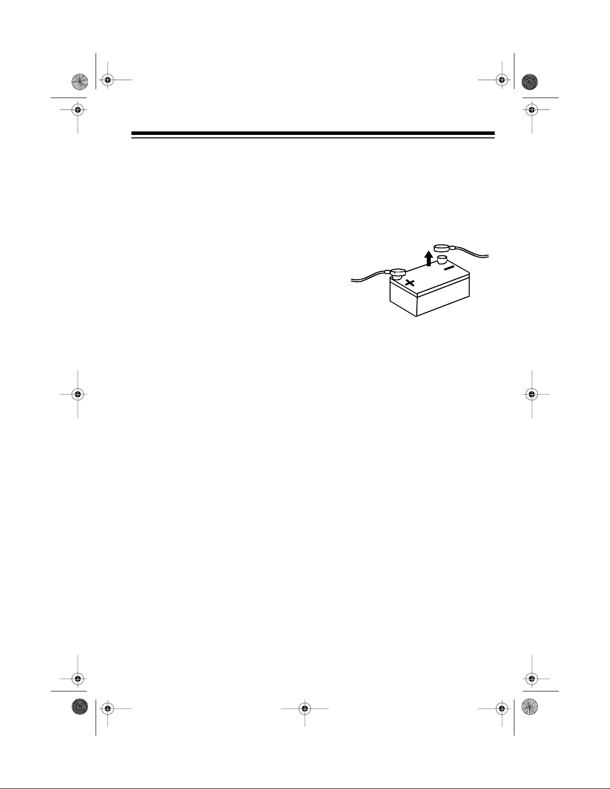
from your vehicle battery’s negative (–) terminal before you begin.
• Be sure your speakers can handle
64 watts of power (16 watts per
channel). Each speaker must
have an impedance of at least 4
ohms. Your local RadioShack
store carries a full line of speakers.
• You must connect the GROUND,
+12V TO IGNITION, and +12V TO
BATTERY wires first, then make
all other connections as described
in the following sections before
you plug the harness with the 14pin connector into the stereo. If
you do not make connections in
the order shown, damage to the
stereo is possible if any wire connections are made incorrectly.
You might need additional wire, depending on your individual autosound
system, to complete the connections.
Your local RadioShack sto re carries a
full line of wire a nd wire mana gement
accessories.
• You must connect a separate wire
to each speaker terminal as
described in the following procedure. Do not use a common wire
or chassis ground for an y s peaker
connection.
7
Page 8
12-215 4.fm Page 8 Wednesday, Ju ly 14, 1999 3: 34 PM
Note: The wires in the wiring harness
have the following colors and labels.
(illus)
Using an Adapter Harness
If you are replacing an existing stereo,
or if your vehicle has been factorywired for autosound components, you
might be able t o use an adapter harness to connect the power and speak ers. RadioShack stores sell adapter
harnesses for most vehicles.
Connecting Ground, Power,
and Optional Components
Follow these steps to connect the harness with the 14-pin connector to
ground, primary and memory backup
power, and optional components.
(illus)
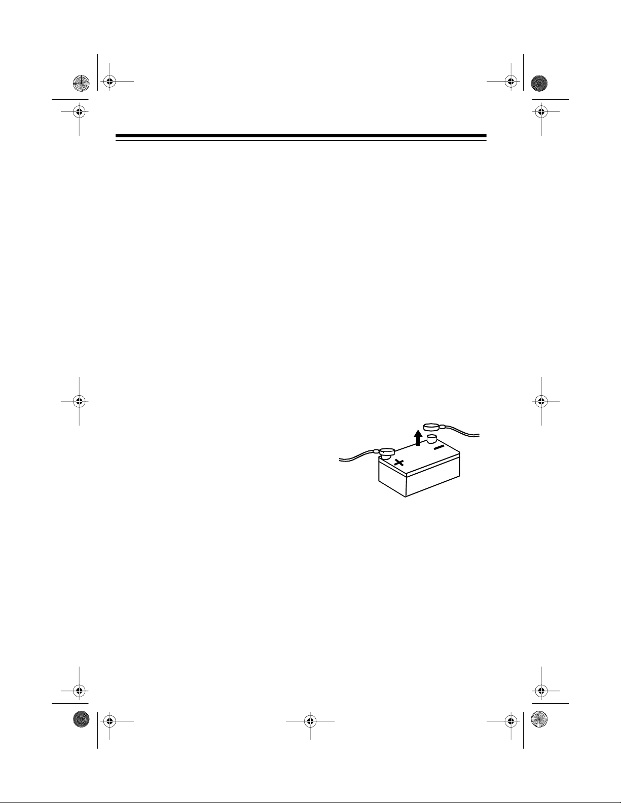
1. Disconnect the cable from your
–
vehicle’s negative (
minal.
) battery ter-
Follow the directions that come with
the adapter harness to temporarily
connect the ground, power, optional
components, and speakers. Then go
to “Connecting the Antenna” on
Page 11.
8
2. Connect the black ground wire to
a chassis ground, such as a metal
screw attached to a metal pa rt of
the vehicle’s frame. Be sure that
the screw is not insulated from the
chassis by a plastic part.
Page 9

y
12-215 4.fm Page 9 Wednesday, Ju ly 14, 1999 3: 34 PM
3. Connect the red power wire (with
in-line fuse holder) to a point in
your vehicle’s fuse block that has
power only when you turn the
vehicle’s key to either the accessory (ACC) or START position.
This connection turns on the stereo when you turn on the ignition
or turn the key to ACC, and turns
off the stereo when you turn off
the ignition. This prevents your
vehicle’s battery from being
drained if you leave the stereo on
when you turn off the ignition.
4. Connect the yellow power/memory wire to your vehicle battery’s
positive (+) terminal or to a point
in your vehicle’s fuse block that
provides a continuous source of
12 volts.
This connection provides power
for the stereo’s components (such
as the CD player), and continuous
power for the stereo’s memory
when the ignition is turned off.
Connecting an Equalizer/
Booster
If you are connecting the stereo to a
separate equalizer or booster, you
need additional wires (not included).
To increase the total power output
from your system, connect the
(right) and L (left) line output jacks on
the back of the stereo and blue/white
wire, if necessary, to the equalizer or
booster.
(illus)
Check the equalizer/booster’s o w ner’s
manual for directions.
R
5. Connect the blue/white wire to any
optional equipment, designed to
run from a switched source, that
you want the stereo to turn on and
off (such as a booster or a power
antenna).
This wire does not provide power
to the components. It s imply turns
them on or off. If you do not use
this wire, secure it with a wire tie
and do not let it touch metal.
Connecting Two Pairs of
Speakers
If you are using both front and rear
speakers, follow these steps to connect the harness with the 14-pin connector to the speakers.
12-2154 Onl
speakers, remove the tape that ho lds
the mounting sleeve in place and slide
the sleeve off of the stereo. Then set
2CH/4CH
to
on the bottom of the stereo
4CH
.
Before connecting the
:
9
Page 10

12-215 4.fm Page 10 Wednesday, J uly 14, 1999 3: 34 PM
Connecting One Pair of
Speakers
(illus)
1. Connect the gray wire t o the right
front speaker’s positive terminal.
This terminal is usually marked
with a plus (+) sign or red mark.
2. Connect the gray/black wire to the
right front speaker’s negative terminal. This terminal might be
marked with a minus (
–
) sign or it
might not be marked at all.
3. Connect the white wire to the left
front speaker’s positive terminal.
4. Connect the white/black wire to
the left front speaker’s negative
terminal.
5. Connect the violet wire to the right
rear speaker’s positive terminal.
For 12-2155:
pair of speakers, follow Steps 1
If you are using only one
–
4 in
“Connecting Two Pairs of Speakers”
on Page 9 to connect the harness with
the 14-pin connector to the speakers.
(illus)
For 12-2154:
If you are using only one
pair of speakers, remove the tape that
holds the mounting sleeve in place
and slide the sleeve of f of the stereo.
Then set
the stereo to
2CH/4CH
2CH
on the bottom of
. Then follow these
steps to connect the harness with the
14-pin connector to the speakers.
6. Connect the violet/black wire to
the right rear speaker’s negative
terminal.
7. Connect the green wire to the left
rear speaker’s positive terminal.
8. Connect the green/black wire to
the left rear speaker’s negative
terminal.
10
(illus)
Page 11
y
y
y
12-215 4.fm Page 11 Wednesday, J uly 14, 1999 3: 34 PM
1. Connect the gray wire t o the right
speaker’s positive terminal. This
termina l is usually ma rked with a
plus (+) sign or red mark.
2. Connect the violet wire to the right
speaker’s negative terminal. This
terminal might be marked with a
minus (–) sign or it might not be
marked at all.
3. Connect the white wire to the left
speaker’s positive terminal.
4. Connect the green wire to the left
speaker’s negative terminal.
Connecting the Antenna
Connect the vehicle’s antenna cable
to the antenna jack on the back of the
stereo.
(illus)
(illus showing harness
being reconnected)
TESTING THE
CONNECTIONS
Turn on your vehicle’ s ignition and install your stereo’s control panel (see
“Installing the Control Panel” on
Page 15).
ON/OFF.
play light.
ON/OFF
The stereo’s buttons and dis-
lights. Then press
Completing the Connections
Make sure you have securely made all
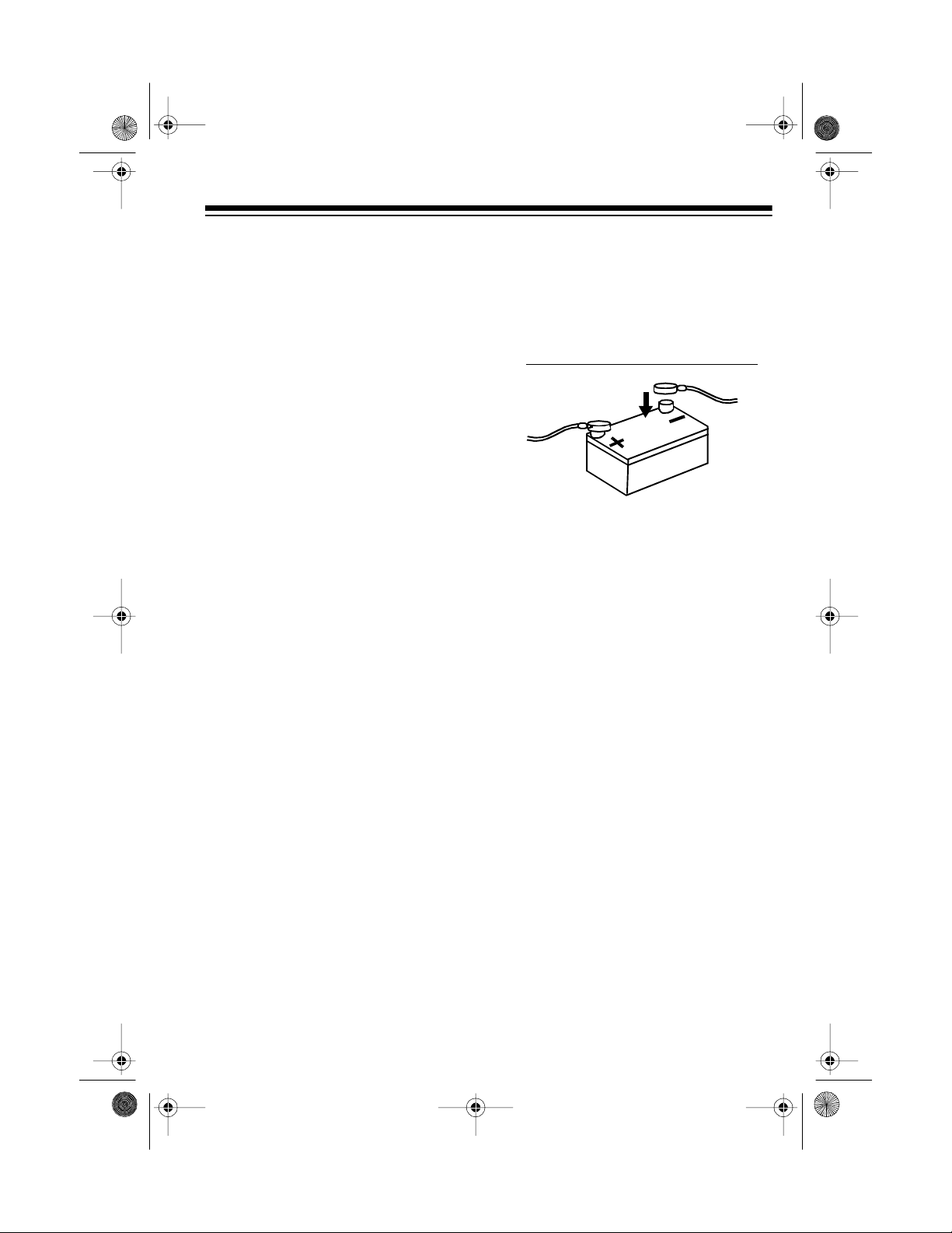
other connections, then plug the harness’ connector into the stereo’s 14pin wiring socket. Reconnect the cable
to the vehicle’s negative (–) battery
terminal.
If the stereo does not work,
atel
disconnect the cable from
our vehicle’s negative (–) batter
terminal.
tions.
After you verify that the buttons/dis-
play light, follow the instructions in
“Mounting the Stereo” on Page 12.
Caution:
testing the connections, be s ure to remove the CD from the stereo before
continuing.
Then recheck y our connec-
If you played a CD while
immedi-
11
Page 12
12-215 4.fm Page 12 Wednesday, J uly 14, 1999 3: 34 PM
MOUNTING THE STEREO
Be sure you verify that the stereo is
connected properly (see “Testing the
Connections” on Page 11). Then follow these steps to mount the stereo.
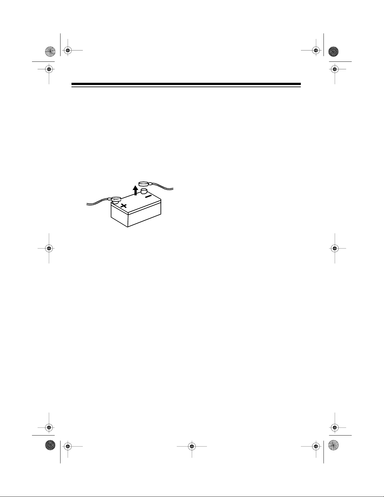
1. Make sure the ignition is turned
off, then disconnect the cable from
your vehicle’s negative (
termi na l.
2. Disconnect the wire harness and
the antenna.
–
) battery
4. Remove the tape that holds the
sleeve in place and slide the
sleeve off of the stereo.
(illus)
Note:
If you have a Cat. No. 122154 stereo, you have already
removed the tape (while setting
2CH/4CH
). Continue with St ep 5.
5. Turn the sleeve around so the flat
tabs on the front are facing you,
then insert it into t he dash. Then
secure the sleeve to the dash by
bending out the tabs with a screwdriver. Bend out all the side tabs.
(new illus)
3. Press
RLS
on the right sid e of the
control panel to remove the control panel.
(illus)
12
(illus)
6. If your vehicle has an existing
mounting hole behind the dash,
use pliers or a
5
/16-inch box-end
Page 13
12-215 4.fm Page 13 Wednesday, J uly 14, 1999 3: 34 PM
wrench to attach the short e nd of t he suppl ied m ount ing bolt t o the bac k of t he
stereo.
(illus)
7. Reconnect the wire harness and
the antenna.
8. Slide the stereo into the sleeve
until it locks int o pla c e.
9. If you are securing the stereo in
an existing mounting hole in the
dash, push the supplied rubber
mounting grommet onto the
mounting bolt.
If necessary, bend the metal strap
to fit your vehicle’s mounting area.
Then use either the supplied
sheet metal screws or the other
bolt (with attached washer) to
attach the other end of the strap to
a solid metal part of the vehicle
under the dashboard. This strap
also helps ensure proper electrical
grounding of the stereo.
(illus - show bolt
(with attached
washers))
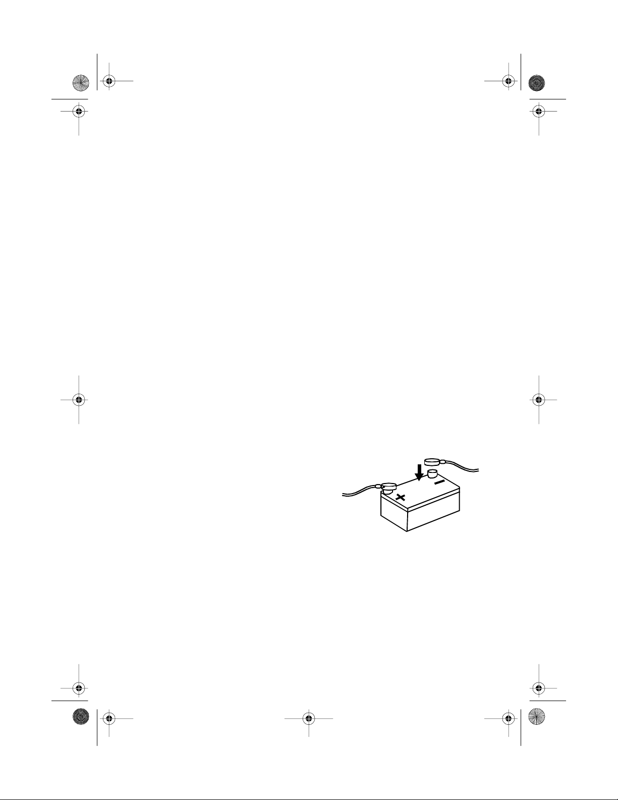
10. Reconnect the cable to the vehicle battery’s negative (–) terminal.
Then install the stereo’s
control panel (see “Installing the
Control Panel” on Page 15).
(illus - show
mounting grommet)
Then push the mounting bolt (covered by the mounting grommet)
through that mounting hole and
make sure it is secure.
Otherwise, you can use one of the
supplied bolts (with attached
washer) to attach one end of the
supplied metal strap to the mounting hole on the back of the st ereo.
Note:
You might need to reset the
stereo’s clock after you reconnect
the cable to the vehicle battery.
13
Page 14
12-215 4.fm Page 14 Wednesday, J uly 14, 1999 3: 34 PM
REMOVING THE STEREO
FROM THE D A SH
If you ever want to remove the stereo
from the dash, follow these steps.
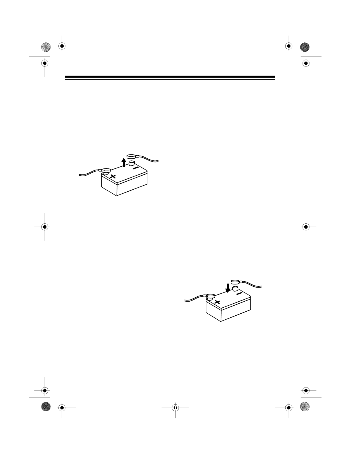
1. Disconnect the cable from your
–
vehicle’s negative (
minal.
2. If you secured the stereo to an
existing mounting hole under the
dash, slide out th e stereo to free
the mounting b olt f rom t he m ount ing hole.
Or, remove the bolt holding the
metal strap attached to the back
of the stereo.
3. Press
RLS
to remove the stereo’s
control panel.
) battery ter-
4. Insert the supplied keys into the
slots at the left an d right sides of
the stereo. Press the k eys downward and slide the stereo out of
the dash.
(illus - show keys on slots)
Note:
The keys are labeled to
show their top edges.
5. Remove the keys from the slots.
6. Disconnect the wire harness and
the antenna.
7. If you are mailing or shipping the
stereo, use a Phillips screwdriver
to reinstall the shipping screw in
the top of the stereo.
8. Reconnect the cable to the vehicle battery’s negative (–) terminal.
14
Page 15

12-215 4.fm Page 15 Wednesday, J uly 14, 1999 3: 34 PM
USING THE CONTROL PANEL
The stereo’s control panel must be in
place for the stereo to operate. When
you remove it, the display turns off
and the stereo cannot be used. This is
a simple but effective security measure.
Any stored stations remain in memory
when the control panel is removed.
INSTALLING THE
CONTROL PANEL
1. Insert the left edge of the control
panel into the left edge of the
recess. The hole in the control
panel interlocks with the tab in the
recess.
REMOVING THE
CONTROL PANEL
1. Press
(illus - show control panel swing)
2. Remove the control panel, then
RLS
. You hear a click and
the control panel swings out.
store it in the supplied carry case.
(illus)
(illus - show pin in recess hole)
2. Gently push the right edge of the
control panel into the recess until
you hear a click.
Caution:
ing pins clean, do not touch the connecting pins in the recess or on the
back of the control panel.
To keep the metal connect-
15
Page 16

12-215 4.fm Page 16 Wednesday, J uly 14, 1999 3: 34 PM
BASIC OPERATION
Unless otherwise noted, all illustrations in this manual sh ow the Cat. No.
12-2155 stereo.
TURNING THE STEREO
ON AND OFF
To turn on the s tereo, press
The buttons and display light. To tu rn
off the stereo, press
ON/OFF
(new illus)
ON/OFF
again.
SETTING THE CLOCK
1. Press
2. While holding down
ON/OFF
reo.
repeatedly press
TRACK +
the correct hour. (To continuously
advance the hour, hold down
TUNE/SEEK TRACK +
to turn on the ste-
CLOCK
TUNE/SEEK
until the stereo displays
.)
3. While holding down
repeatedly press
TRACK –
the correct minute. (To continuously advance the minute, hold
down
.
Notes:
• The clock resets the s econds to 0
as soon as you stop advancing
the minute.
• You can use a watch with a sweep
second hand or other time reference to set the clock to the exact
second at the beginning of an
hour. When the time reference
reaches the beginning of an hour,
hold down
The clock resets the minutes and
,
seconds to 00 and advances the
hour if the minutes were past 29.
until the stereo d isplays
TUNE/SEEK TRACK –
(illus)
CLOCK
, then press 6.
CLOCK
TUNE/SEEK
,
.)
16
(illus)
Page 17

12-215 4.fm Page 17 Wednesday, J uly 14, 1999 3: 34 PM
ADJUSTING THE SOUND
When you listen to your stere o, adjust
these controls to suit your listening
preferences.
(illus)
AUDIO CONTROL SEL +/–
edly press or hold down to increase or
decrease the volume.
ume level number appear.
Warning:
not listen at high volume levels. Slowly
increase the volume to a comfortable
listening level.
AUDIO CONTROL SEL
press until
and a number appear on t he display,
then repeatedly press or hold down
or – within 5 seconds to change the
stereo’s bass, treble, balance, or fader
settings.
To protect your h earing, do
bAS, TRE, bAL, or FAd
— Repeat-
VOL
and a vol-
— Repeatedly
you adjust the fader toward the
rear speakers,
appear.
bAS, TRE, bAL
•If
number disappear before you
press
AUDIO CONTROL SEL
setting you want reappears, then
repeatedly press or hold down
or – to set it.
• To set bass, treble, balance, and
fader to their center (middle) settings, hold down
SEL
stereo beeps twice.
LOUD
the low ranges of sounds, repeatedly
press
off loudness, repeatedly press
until
+
+
or –, repeatedly press
for about 3 seconds until the
(12-2154 Only)
LOUD
until ON appears. To turn
OFF
appears.
R
and a number
FAd
, or
until the
AUDIO CONTROL
— To increase
(illus)
and the
+
LOUD
Notes:
• When you adjust the balance
toward the left speakers,
number appear on the display.
When you adjust the balance
toward the right speakers,
number appear.
• When you adjust the fader toward
the front speake rs,
ber appear on the display. When
L
and a
R
and a
F
and a num-
FAVORITE SOUND
MEMORY (12-2155
ONLY)
You can store your stereo’s current
volume, bass, treble, balance, and
fader settings into memory. This lets
you select the best sound for the music you listen to and save that sound,
17
Page 18

12-215 4.fm Page 18 Wednesday, J uly 14, 1999 3: 34 PM
so you can recall it later. You can store two FSM (favorite sound memory) settings.
Follow these steps to store an FSM
setting.
until
blinks
FSM
FSM I
FSM
until
or
1. Repeatedly press
I
FSM II
or
2. Adjust the volume, bass, treble,
balance and fader using the information in “Adjusting the Sound”
on Page 17.
FSM I
Note:
while you adjust the controls.
3. When you finish adj usting t he stereo’s settings, hold down
the stereo beeps twice. This indicates that the settings you
entered are saved in the FSM setting you selected.
To select an FSM setting you sav ed,
repeatedly press
FSM II
those settings you entered in Step 2.
appears. The stereo is set to
FSM
appears.
(illus)
FSM II
or
FSM
until
CLOCK
While the radio or a CD is playing,
CLOCK
press
to display the clock.
(new illus)
T URNING THE KEY T ONE
ON AND OFF
The stereo is preset to beep when you
press most buttons. To turn the key
tone off, turn the stereo off, then hold
AT P
down
ming) and
onds until b
To tu rn the key tone back on, turn the
stereo off, then hold down
together for about 3 seconds u ntil
ON
appears.
(automatic travel program-
6
together for about 3 sec-
P
(beep)
OFF
appears.
AT P
and
bP
6
To turn off FSM, repeatedly press
FSM I
until
from the display. The stereo is set to
its default settings.
and
FSM II
FSM
disappear
DISPLAYING THE
18
(illus)
Page 19

g
g
12-215 4.fm Page 19 Wednesday, J uly 14, 1999 3: 34 PM
RADIO OPERATION
PLAYING THE RADIO
1. Press
reo. The radio au tomatically tun es
to the last station and band
selected.
2. Press
band.
band is selected.
appears when an FM band is
selected.
3. Tune to the desired station in one
of the following ways.
ON/OFF
(add new illus)
BND
AM
to turn on the ste-
to select the desired
appears when the AM
FMI
or
(illus)
FMII
Manual Tunin
TUNE/SEEK TRACK –
press
tune down or up the selected
band.
Seek Tunin
SEEK TRACK –
second to tune to the next lower
or higher station.
4. Press
Notes:
• appears when an FM signa l
• See “Adjusting the Sound” on
AUDIO CONTROL SEL +
to increase or decrease the volume as desired.
is received in stereo.
Page 17 for information about
changing the stereo’s other settings.
Repeatedly
:
Hold down
:
or + for about 1
(illus)
or + to
TUNE/
or
–
MEMORY TUNING
(illus)
You can manually store up to 6 AM
and 12 FM stations in memory groups.
Each memory group (AM, FMI, and
FMII) holds up to six stations. You can
also automatically store the first 6
strong AM and f irst 6 strong FM s tations in a separate automatic travel
programming memory.
19
Page 20

12-215 4.fm Page 20 Wednesday, J uly 14, 1999 3: 34 PM
Storing Stations
1. Repeatedly press
the desired memory group (
FMI
2. Tune to the station you want to
store.
3. Hold down the desired memory
channel button until
ory channel number, and the frequency flash once on the d isplay.
The s tation is stored.
(illus - callout ‘Memory Channel
, or
FMII
Buttons)
BND
to select
).
P-
, the me m -
AM
AT P
2. Hold down
programming) for about 2 seconds. The stereo displays
,
scans the selected band, and
automatically stores the first 6
strong stations it finds in automatic travel programming memory.
After the stereo stores all six stations in the selected band, it tunes
to the first station it stored in automatic travel programming memory.
(automatic travel
(illus)
ATP
,
Storing Stations in Automatic
Travel Programming Memory
The stereo can sto re the first 6 strong
AM and the first 6 strong FM stations it
finds into its automatic travel programming (ATP) memory. This memory is
separate from the stereo’s memory
groups, so it does not replace the stations you manually stored.
1. Repeatedly press
the desired band (
FMII
).
20
BND
to select
AM, FMI
, or
If the stereo could not find
Note:
any stations,
appears on the display. Press
BND
or select another station to
listen to the radio.
3. Repeatedly press
disappears to get out of au tomat ic
travel progra mming.
P - 1 - - -
BND
until
ATP
Selecting a Stored Station
To select a station you manually
stored in AM, FMI, or FMII, repeatedly
BND
press
ory group, then press the desired
memory channel button.
to select the desired mem -
Page 21

12-215 4.fm Page 21 Wednesday, J uly 14, 1999 3: 34 PM
Note: Do not hold down the mem ory
channel button. This stores the currently tuned station into that location.
To select a station you automatically
stored in automatic travel programming memory, follow these steps:
1. Repeatedly press
the desired band (
FMII
).
ATP
2. Press
for less than 1 second
BND
to select
AM, FMI
, or
to select the desired memory station. Each time you press
ATP
, the
stereo advances to the next memory channel.
Notes:
ATP
• Do not hold down
. This
causes the stereo to automatically scan and store the first 6
strong stations it finds into its
automatic travel programming
memory.
Scanning Stored Stations
The radio can scan a ll stored stations
in the selected band, pausing for 5
seconds at each station.
To start scanning station s you manually stored, repeatedly press
select the desired memory group, then
hold down
BND
until
SCN
To scan the stations in the automatic
travel programming memory, repeatedly press
band, press
then hold down
BND
to select the desired
ATP
so
BND
ATP
until
pears.
As the radio scans each memory
channel,
P-
and the channel number
flash and the frequency is displayed.
After scanning all memory channels,
the stereo returns to the original station.
BND
appears.
appears,
SCN
to
ap-
• If the stereo could not find a ny
strong stations,
P - x - - -
(where x is one of the stereo’s
6 channel numbers) appears for
the empty channels.
To stop scanning when the radio
pauses at a station you want to listen
to, press
BND
again during the pause.
21
Page 22
12-215 4.fm Page 22 Wednesday, J uly 14, 1999 3: 34 PM
CD PLAYER OPERATION
Cautions:
• Play only CDs that
have this mark on
them:
• The CD player has a wide
dynamic range. As a result, if you
turn your stereo’s volume up too
high during soft (low volume) sections of a program, your speakers
might be damaged when a sudden loud passage occurs.
• If the CD player is jolted during
play , the rotation speed might suddenly change or the CD player
might make an unusual noise.
This is not a malfunction.
PLAYING A CD
1. Press
2. Insert a CD (label side up) in the
ON/OFF
reo.
slot. The stereo automatically
switches to CD play mode if the
radio is playing and displays
In
. Then the display shows
cd
,
starts to play from Track 1.
to turn on the ste-
TR01
, and
, and the CD
cd
played, and the CD starts to play
from the point where you last
stopped it.
(illus)
After the stereo plays the entire
CD, it automatically repeats all
tracks, start ing wit h T r a ck 1 .
3. Press
4. To pause p layback, press
5. To remove a CD from the CD
+
or – to increase or
decrease the volume as desired.
See “Adjusting the Sound”
Note:
on Page 17 for information about
changing the stereo’s other settings.
CD
TR
.
and the track number flash. To
resume play, press
If you pause a CD for m ore
Note:
than 5 minutes, the stereo turns
off.
player, press .
(illus)
CD
again.
EJ cd
appears.
(illus)
If a CD is already in the CD player
( appears on the display),
CD
simply press
The stereo displays
the number of the track you last
22
to play the CD.
cd, TR
, and
Page 23

12-215 4.fm Page 23 Wednesday, J uly 14, 1999 3: 34 PM
Notes:
• If you eject a CD while it is playing
and do not remove it from the CD
player, the stereo automatically
draws the CD back in and starts
playing again after about 5 seconds.
• If you eject a CD then remove it
from the CD player, the stereo dis-
no cd
plays
you press
(or the current time if
CLOCK
).
SELECTING A TRACK
To select a track on the loaded CD,
press
play to advance to the next track or
TUNE/SEEK TRACK –
start of the current track. Repeatedly
press
lect the next or previous track.
TUNE/SEEK TRACK +
to go ba ck to the
TUNE/SEEK TRACK +
during
or – to se-
(illus - arrow TUNE/SEEK TRACK)
SHUFFLE PLAY
You can set the stereo to randomly
select and play tracks from the loaded
CD. After each track plays, the stereo
automatically selects another track
and plays it until you stop shuffle play.
To begin shuffle play, press
SHF
appears during shuffle play.
(illus - arrow SHUF key)
SHUF/1
.
AUDIBLE SEARCH
To search for a particular section of a
track, hold down
TUNE/SEEK TRACK –
or
The stereo rapidly plays the CD either
forward or backward (like cueing or reviewing a cassette tape). When you
hear the section you want, release
TUNE/SEEK TRACK +
TRACK –
to resume normal play.
TUNE/SEEK TRACK +
during play.
TUNE/SEEK
or
To stop shuffle play, press
again to resume normal play.
appears.
Note: You can use audible search
during shuffle play (see “Audible
Search”).
SHUF/1
SHF
dis-
23
Page 24

12-215 4.fm Page 24 Wednesday, J uly 14, 1999 3: 34 PM
REPEAT PLAY
You can set the stereo to repeat a single track on the loaded CD.
To repeat a track, press
RPT
play.
When the track ends, it automatically
repeats.
To stop repeating the track and resume normal play, press
disappears.
Scanning the Tracks
appears during repeat play.
(illus - arrow RPT key)
RPT/2
RPT/2.
during
RPT
To stop scanning, pre ss
at the desired track to resum e normal
SCN
play.
disappears.
SCN/3
again
SWITCHING BETWEEN
THE CD AND THE RADIO
You can temporarily stop a CD and listen to the radio by pressing
CD stops and the radio tunes to the
last station selected.
To continue playing the CD from the
point where you stopped it, press
BND
. The
CD
.
You can set the s te reo to play the first
10 seconds of each t rack on the loa ded CD, so y ou can find the track you
want to listen to.
To begin scanning, press
appears during scanning.
(illus - arrow SCN key)
24
SCN/3
.
SCN
Page 25
12-215 4.fm Page 25 Wednesday, J uly 14, 1999 3: 34 PM
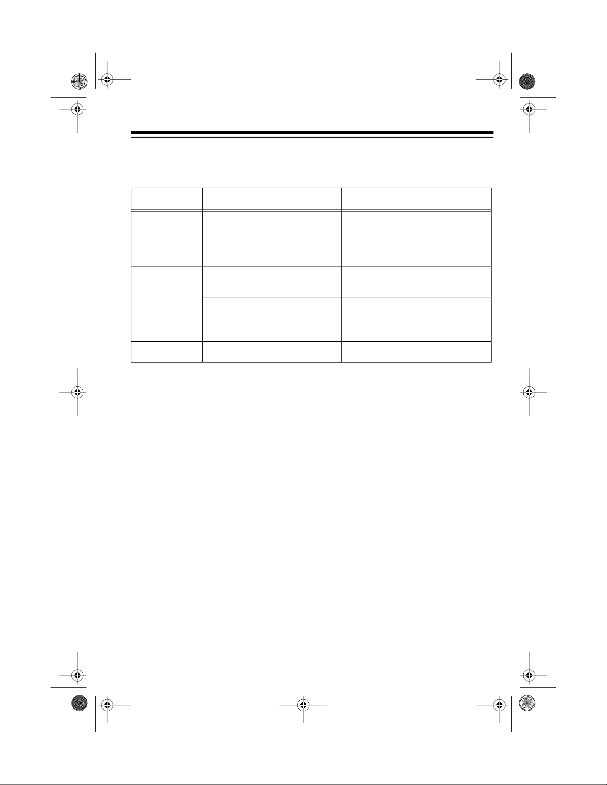
TROUBLESHOOTING
If your stereo’s CD player is not working as it should, it displays an error indicator. If
it is a numbered error, it ejects the CD. Try these suggestions.
Indicator Problem Suggestion
E01
E07
no cd
If the stereo still does not operate properly, the c onnecting pins in the r eces s or on
the back of the control panel might be dirty. Use a soft cloth or a contact cleaner
(such as Cat. No. 64-4340) to clean them.
Loading and/or unloading
operation fails.
The CD is loaded incorrectly. Reload the CD with the label
The CD is dirty or defective. Clean the CD (see “CD Care
No CD is loaded. Load a CD.
(illus)
Make sure a CD is loaded. If it
is not, insert the CD properly. If
it is, eject the CD and load it
again.
side up.
Tips” on Page 28) or t ry another CD.
If the stereo still does not operate properl y, take it to your local RadioShack store
for assistance.
25
Page 26

12-215 4.fm Page 26 Wednesday, J uly 14, 1999 3: 34 PM
RESETTING THE
STEREO
If your stereo locks up or does not
work properly, remove the front panel
and use a straightened paper clip to
press the reset button on the bottom
left side of the inside panel for about 1
second.
(illus)
26
Page 27
12-215 4.fm Page 27 Wednesday, J uly 14, 1999 3: 34 PM
CARE AND MAINTENANCE
Your Optimus High-Power In-Dash AM /FM Stereo CD Player is a n example of superior design and craftsmanship. The follow ing suggestions will help you care for
your stereo so you can enjoy it for years.
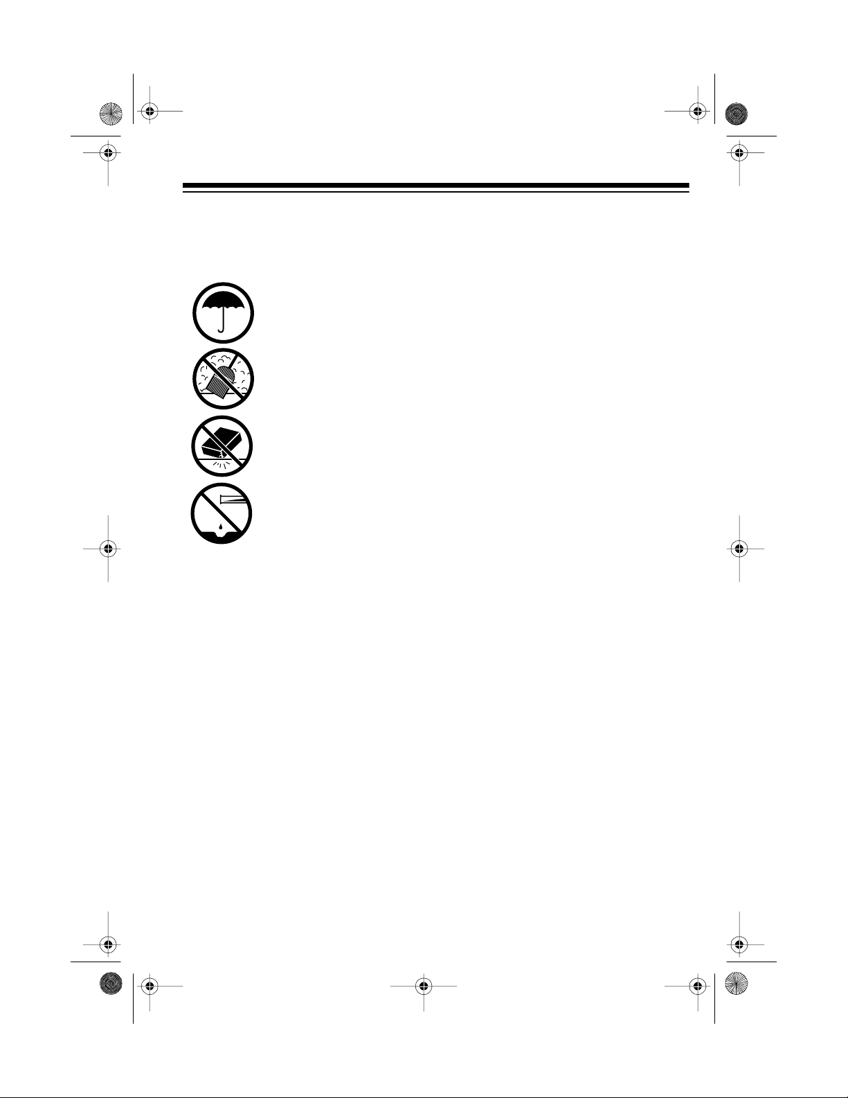
Keep the stereo dry. If it gets wet, wipe it dry immediately. Liquids
might contain minerals that can corrode the electronic circuits.
Keep the stereo away from dust and dirt, which can cause premature
wear of parts.
Handle the stereo gently and carefully. Dropping it can damage circuit boards and cases and can cause the stereo to work improperly.
Wipe the stereo with a damp cloth occasionally to keep it looking
new. Do not use harsh chemicals, cleaning solvents, or strong detergents to clean the stereo.
Modifying or tampering with the stereo’s internal components can cause a malfunction, invalidating your stereo’s warranty and voiding your FCC authorization to operate it. If your s tereo is not performing as it should, take it t o your local RadioShack
store for assistance.
THE FCC WANTS YOU TO KNOW
Your stereo might cause TV or radio interference even when it is operating properly. To determine whether your stereo is causing the interference, turn off your stereo. If the interference go es away, your stereo is causing i t. Try to eliminate the
interference by:
• Moving your stereo away from the receiver
• Contacting your local RadioShack store for help
If you cannot eliminate the interference, the FCC requires that you stop using your
stereo.
27
Page 28
12-215 4.fm Page 28 Wednesday, J uly 14, 1999 3: 34 PM
CD CARE TIPS
Even though a CD is very durable, you
should handle it with care. We recom mend the following precautions.
• Keep the CD in its protective case
or sleeve when you a re not playing it.
• Handle a CD by its edges to avoid
fingerprints which can prevent the
CD player’s laser beam from
accurately reading the CD. Your
local RadioShack store sells a
suitable CD cleaner kit.
• Do not write on either side of the
CD, particularly the non-label
side. (Signals are read from the
non-label side.)
• Keep the CD dry. A water drop
can act as a lens and affect the
laser beam’s focus.
• If you park your vehicle in the sun,
temperatures inside the vehicle
can easily reach level s that could
damage your CDs. To prevent
heat damage, avoid leaving your
CDs in your vehicle.
REPLACING A FUSE
If the stereo does not operate, you
might need to replace the red power
wire’s 1-amp 1
supplied spare fuse (Cat. No. 270-
1005). If the clock resets or stored stations are lost w hen the ignition is off,
you might need to replace the 10-amp
blade-type fuse on the stereo’s back
panel with the supplied spare fuse
(Cat. No. 270-1081). Check both fus es.
Caution:
ings other than those specified here.
Doing so might damage your stereo.
Do not use a fuse with rat-
Replacing the Red Power
Wire’s Fuse
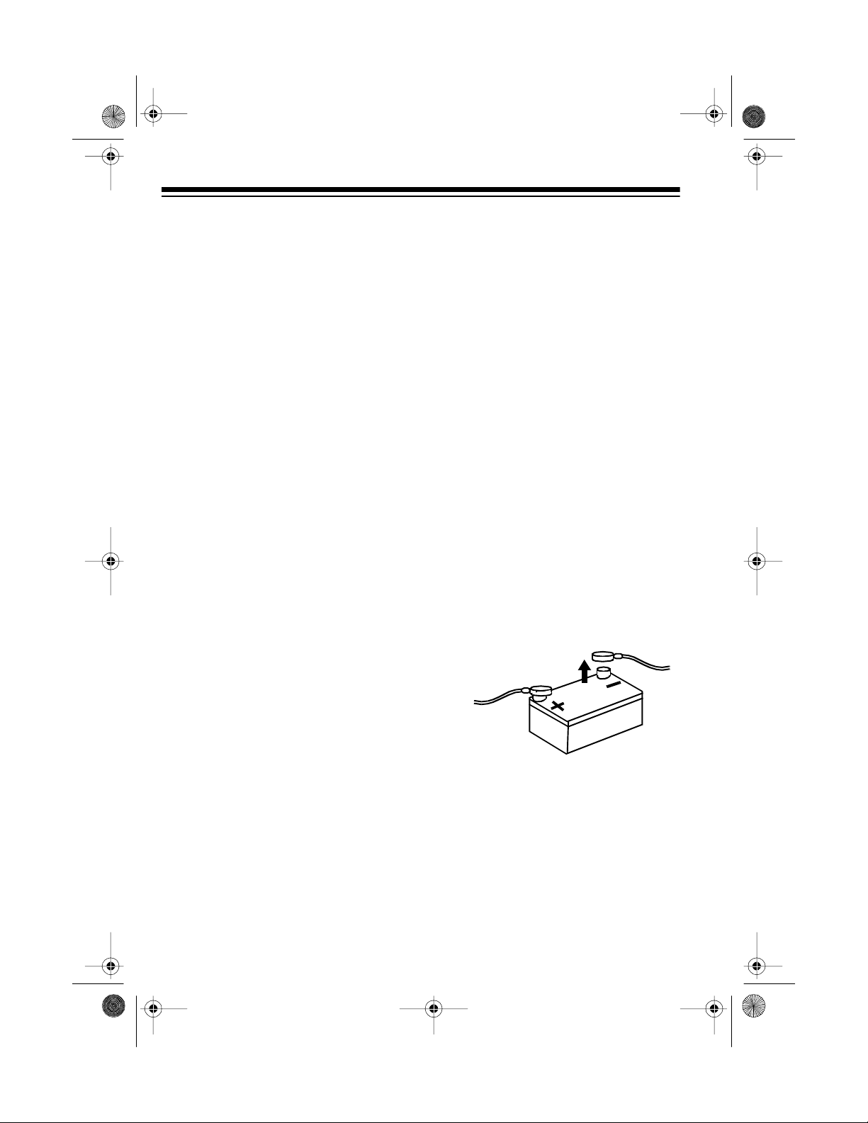
1. Disconnect the cable from your
vehicle’s negative (
minal.
1
/4-inch fuse with the
–
) battery ter-
If a CD skips when you try to play it, it
might be scratched. Your local RadioShack store sells a Scratch ,n Fix
kit (Cat. No. 42-127) that might help
remove the scratch and stop the skip.
See also “Troubleshooting” on
Page 25.
28
2. Push together and twist the fuse
holder’s parts on the red power
wire until they spring apart. Then
remove the fuse.
(illus - show red fuse holder)
Page 29
12-215 4.fm Page 29 Wednesday, J uly 14, 1999 3: 34 PM
3. If the fuse is blown, replace it. Use
only the supplied 1
1
/4-inch fuse or
a replacement fuse with the
proper rating (such as Cat. No.
270-1005). The fuse must be 1
amp.
4. Reassemble the fuse holder by
inserting the fuse into the longer
of the fuse holder’s ends, and
pushing together a nd twisting the
two parts until they latch together.
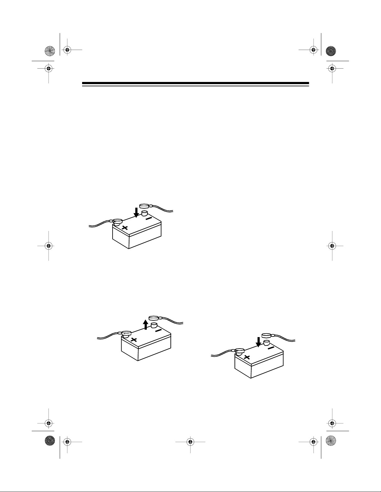
5. Reconnect the cable to the vehicle battery’s negative (–) terminal.
Replacing the Blade-Type
Fuse
1. Disconnect the cable from your
vehicle’s negative (
minal.
–
) battery ter-
2. If the back of the stereo is not
accessible, remove the stereo
from the dash as described in
“Removing the Stereo From the
Dash” on Page 14.
3. Grasp the fuse’s plastic end and
pull it out.
(illus - show blade-type fuse holder)
4. If the fuse is blown, replace it. Use
only the supplied blade-type f use
or a replacement fuse with the
proper rating (such as Cat. No.
270-1081). The fuse must be 10
amps.
5. Grasp the new fuse’s plastic end
and push it in.
6. If necessary, reinstall the stereo in
the dash.
7. Reconnect the cable to the vehicle battery’s negative (–) terminal.
29
Page 30

12-215 4.fm Page 30 Wednesday, J uly 14, 1999 3: 34 PM
SPECIFICATIONS
RADIO
FM (Nominal) AM (Nominal)
Frequency Range 88–108 MHz 530–1710 kHz
Frequency Response (± 3 dB) 50–12500 Hz N/A
IF Rejection 85 dB 40 dB
Image Rejection 60 dB 25 dB
Selectivity 66 dB 100 dB
Signal-to-Noise (S/N) Ratio 60 dB 49 dB
Stereo Separation 30 dB N/A
Usable Sensitivity 17 dBf 29 dB
CD PLAYER
Frequency Response . .......................................................................... 5–20000 Hz
Signal-to-Noise Ratio ..................................................................................... 65 dB
Harmonic Distortion ..................................................................................... 0.08 %
Wow and Flutter ............................................................................. Not Measurable
CDs Used (Diameter) .................................... 5-inch (120 mm) and 3-inch (80 mm)
SIGNAL FORMAT
D-A Conversion ......................................................................................1 Bit Linear
Transmission Bit Rate .......................................................................... 1.4 Mbit/sec
Sampling Frequency .................................................................................... 8 times
Pick-Up System .............................................................................. Optical Pick-Up
Optical Source ................................................................................................ Laser
Wavelength .................................................................................................. 785 nm
Rotation Speed ............................................................ ..... ....... ....... ... 200–500 rpm
Error Correction .............................................................................................. CIRC
Number of Channels ..................................................................... 2-channel stereo
30
Page 31

12-215 4.fm Page 31 Wednesday, J uly 14, 1999 3: 34 PM
GENERAL
Power Source ................................................................. 12V DC Negative Ground
Speaker Output Impedance . ........................................................................ 4 Ohms
Maximum Power ................................ 25 Watts ¥ 2CH or 6 Watts ¥ 4CH (12-2154)
25 Watts ¥ 4CH (12-2155)
Power Output (RMS) ......................... 16 Watts ¥ 2CH or 4 Watts ¥ 4CH (12-2154)
16 Watts ¥ 4CH (12-2155)
Chassis Size (HWD) ........................................................ 2.28 ¥ 7.40 ¥ 7.08 Inches
(58 ¥ 188 ¥ 180 mm)
Weight ......................................................................................................... 52.9 oz
(1.5 kg)
Specifications are typical; individual units m ight vary. Specifications are subj ect to
change and improvement without notice.
31
Page 32
12-215 4.fm Page 32 Wednesday, J uly 14, 1999 3: 34 PM
Limited One-Year Warranty
This product is warrant ed by RadioShac k against man ufacturing d efects in materia l and workmanship under normal use for one (1) year from the date of purchase from RadioShack company-owned
stores and authorized RadioShack franchisees and dealers. EXCEPT AS PROVIDED HEREIN, RadioShack MAKES NO EXPRESS WARRANTIES AND ANY IMPLIED WARRANTIES, INCLUDING
THOSE OF MERCHANTABILITY AND FITNESS FOR A PARTICULAR PURPOSE, ARE LIMITED
IN DURATION TO THE DURATION OF THE WRITTEN LIMITED WARRANTIES CONTAINED
HEREIN. EXCEPT AS PROVI DED HEREIN, Rad ioShack SH ALL HAVE NO LIABILIT Y OR RESPONSIBILITY TO CUSTOMER OR ANY OTHER PERSON OR ENTITY WITH RESPECT TO ANY
LIABILITY, LOSS OR DAMAGE CAUSED DIRECTLY OR INDIRECTLY BY USE OR PERFORMANCE OF THE PRODUCT OR ARI SING OUT OF ANY BREACH OF THIS WARRANTY, INCLUDING, BUT NOT LIMITED TO, ANY DAMAGES RESULTING FROM INCONVENIENCE, LOSS
OF TIME, DATA, PROPERTY, REVENUE, OR P ROFIT OR ANY INDIRECT, SPECIAL, INCIDENTAL, OR CONSEQUENTIAL DAMAGES, EVEN IF RadioShack HAS BEEN ADVISED OF THE
POSSIBILITY OF SUCH DAMAGES.
Some states do not allow the limitations on how long an implied warranty lasts or the exclusion of incidental or consequential damages, so the above limitations or exclusions may not apply to you.
In the event of a product defect during the warran ty period, take the product and the RadioShack
sales receipt as proof of pur cha se date to any RadioS hack s tore. Radi oSha ck wil l, at its option, unless otherwise provided by law: (a) correct the defect by product repair without charge for parts and
labor; (b) replace the produc t with one of the same or similar design; or (c) refund the purchase
price. All replaced parts and pr oducts, and pro ducts on which a refund is made, become the property of RadioShack. New or rec onditioned parts and products may be used in the performance of
warranty service. Repa ired or replaced parts and produ cts are warranted for the remainder of the
original warranty period. You will be charged for repair or replacement of the product made after the
expiration of the warranty period.
This warranty does not cover: (a) damage or failure caused by or attributable to acts of God, abuse,
accident, misuse, impr oper or abnormal usa ge, failure to fol low i nstruct ions, improper instal lation or
maintenance, alterati on, lightning or other incidence of exc ess voltage or current; (b) any repairs
other than those provi ded by a RadioShack Autho rized Service Facility; ( c) consumables such as
fuses or batteries; (d ) cosmeti c dam age; (e) transp ortatio n, sh ipping or insuranc e c osts; or (f) cos ts
of product removal, installation, set-up service adjustment or reinstallation.
This warranty gives you specifi c legal rights, and you may also have oth er rights which vary from
state to state.
RadioShack Customer Relations, Dept. W, 100 Throckmorton St., Suite 600, Fort Worth, TX 76102
We Service What We Sell
3/97
RadioShack
A Division of Tan dy Corporation
Fort Worth, Texas 76102
1ED6P10A11200A
2A8 Printed in Malaysia
 Loading...