

Page 1
16-546 .fm Page 1 Tues day, July 20, 1999 4:2 5 PM
Cat. No. 16-546
OWNER’S MANUAL
Please read before using this equipment.
MODEL 109
4-Head HQ VHS VCR
Page 2
g
y
g
g
g
g
g
g
y
y
g
y
g
y
y
y
g
y
g
g
g
g
g
y
g
y
y
y
g
g
y
y
y
y
y
y
y
y
g
y
y
y
g
g
g
g
g
g
g
GROUND CLAM PS
NEC - NATI ON AL ELE CTRI CAL C ODE
EXAMPLE OF ANT ENNA GROUNDI NG AS P ER
NATIONAL ELE CTRICAL CODE
WIRE
DISCHARGE UNIT
(NEC SECTION 810-20)
GROUNDING CONDUCTORS
(NEC SECTION 810-21)
ELECTRODE SYSTEM
(NEC ART 250, PART H)
SERVICE
EQUIPMENT
CLAMP
ANTENNA
LEAD IN
ANTENNA
POWER SERVICE GROUNDING
GROUND
ELECTRIC
FIGURE A
16-546 .fm Page 2 Tues day, July 20, 1999 4:2 5 PM
IMPORTANT SAFETY INSTRUCTIONS
Read instructions
1.
— All the safety and operatin
instructio ns shou ld b e read b efore t he ap pli ance is operated.
Retain Instructions
2.
— The safet
and opera ting instruc-
tions should be retained for future reference.
Heed Warnings
3.
the operatin
Follow Instructions
4.
— All warnin
s on the ap plianc e an d in
instructions should be adhered to.
— All operatin
and use instructions
should be followed.
Cleaning
5.
cleanin
ers. Use a damp cloth for cleanin
Attachments
6.
mended b
— Unplu
the VCR from t he wall outle t before
it. Do no t use liq uid clea ners or ae rosol clea n-
.
— Do not use attachments not recom-
the VCR manufacturer as they may cause
hazards.
Water and Moisture
7.
— Do not us e thi s V CR nea r w ater
— for e xample, near a bath tub, wash bowl, kitchen si nk,
or laundr
tub, in a wet base ment, or near a swi mmin
pool.
Accessori es
8.
— Do not plac e this VCR on an unstable
cart, stand , tripod, brac ket, or table. The VCR ma
serious injury to someone an d serious damage
causi n
to the appliance. Use onl
bracket, or t able recommend ed b
sold with the VCR. An
with a cart, stand, tripod,
the manufacturer or
mounting of the appliance should
follow th e manufacturer ’s instructi ons and should us e a
mountin
accessory recommend ed by the manu facturer.
An applianc e and cart com bi nation shou l d be moved with
care.
Quick sto ps, excessiv e force, a nd uneven su rfaces ma
cause an appl i ance and cart co mbination t o overturn.
fall,
This VCR sho uld ne ve r be pl aced ne ar or ov er a radi ator
or heat re
ister. This VCR should not be placed in a builtin install ation such as a boo kcase or rac k unless prop er
ventilation is provided or the manufacturer’s instructions
have bee n adhered to.
Power Sources
10.
— This VCR should be operated on l
from the type of po wer source indicated o n the marki n
labe l. I f you are not sur e of th e type of power s upplied to
our home, consul t your appli ance deale r or loca l power
. For VCRs intended to operate from batter
compan
power or other sources, refer to the o perating instructions.
Grounding and Polarization
11 .
with a polarized alternatin
in
one b lade wi der t han th e ot her). Th is plug will fit into
the power ou tle t o nl
one way. This is a safety feature. If
— Thi s VCR is equipp ed
-curren t line plug (a plug hav-
ou are unable to insert the plug fully into the outle t, tr
reversing the plug. If the plug should still fail to fit, contact
our electrician to replace your obsolete outlet. Do not
defeat the safet
Power-Cord Protection
12.
be routed so the
pinched b
purpose of the polarized pl ug.
— Power-suppl
cords s hould
are not likely to be walked on or
items placed upon or against them , payin
particula r atte ntion t o cords at plugs, conven ience re ce ptacles, and the point where the
Outdoor Antenna Grounding
13.
or cable s
stem is con nected to the VCR , be sure the
antenna or cable s
some protection a
char
es.
ainst v oltage surges and built -up sta t i c
stem is grounded so as to provide
exit from the appliance.
— If an outside antenna
Section 81 0 of the Natio nal Ele ctrical Code, ANSI/N FPA
No. 70-198 4, prov ides in format ion wi th re spec t to pr oper
rounding of the mast and sup porting structure, ground-
of the le ad- in wi re t o an an tenn a d isc harge unit, size
in
of
rounding conduct ors, location o f antenna-disch arge
unit, connection to
ments for the
rounding electrodes, and require-
rounding electrode.
2
Ventilation
9.
— Slots and o pen in
s in the cabinet and the
back or bottom are provided for ventilation and to ensure
reliable ope ration of t he VCR and t o prot ect it from o ve rheatin
. These openings must not be blocked or c overe d.
The openin
VCR on a bed, sofa, ru
s should never be blocked by placing the
, or ot he r s i mi l ar sur f ace.
© 1996 Tandy Corporation.
Optimus is a registered trademark used by Tandy Corporation
RadioShack is a trademark used by Tandy Corporation.
All Rights Reserved.
Page 3
g
g
y
g
g
y
y
g
g
y
g
g
y
g
y
y
g
g
g
g
g
y
y
y by
g
y
y
y
g
g
y
g
y
y
y
y
g
y
g
g
CAUTION
16-546 .fm Page 3 Tues day, July 20, 1999 4:2 5 PM
Lightning
14.
durin
unused for l on
outlet and d isconn ect the antenna or cabl e s
will prevent dama
power-line sur
Power Lines
15.
be locate d i n t he vicinit
electric li
such power lines or circuits. When installin
antenna s
from touchin
them mi
Overloading
16.
sion cords as this can re sult in a risk of fire or elect ric
shock.
Object and Liquid Entry
17.
kind into this VCR through openings as they may touch
dan
result in a fire or electric shock. Never s pill liquid of an
kind on the VCR.
Servicing
18.
as openin
qualifie d service pers onnel.
Damage Requiring Service
19.
the wall outlet and refer servicin
sonnel under the followi n
• When the power -suppl
• If liquid has been spilled or objects have falle n into the
• If the VCR has been exposed to ra i n or water.
• If the VCR does not ope rate no rmal l
• If the VCR has been dropped or the cabinet has been
• When the VCR exhibits a distinct chan
Replacement Parts
20.
required, be sure the service technician has used
replacement parts, specified b
have the sa me c harac teri stic s as the ori
thorized substitutions ma
injur
— For added protecti on for this VCR receiv er
a lightning storm, or when it i s left unattended and
erous voltage points o r short out parts that could
erous voltage or other hazards. Refer all servicing to
ed.
fra
VCR.
operatin
are covered b
adjustment of other controls ma
and will often require extensive work b
technici an to restore th e VC R to its normal operation.
dama
mance — t hi s indicates a n eed for service.
to persons or other hazards.
periods of time, unplug it from the wall
e to the VCR due to lightning and
es.
— An outside antenna s
of overhead power lines or other
ht or power circuits, or whe re it can fall into
stem, extreme care should be taken to keep
such power lines or circuits as contact with
ht be fatal.
— Do not overload wall outlets and exten-
— Neve r push ob jects o f an
— Do not attempt to service this VCR
or remov ing covers may expose you to dan-
— Unplu
conditions:
cord or plug is damaged or
instructions. Adjust only those c ontrol s that
the operating instructions, as improp er
ed.
— When replacement parts are
result in fire, electric shock,
stem should not
an outside
this VCR from
to qualified service per-
following the
result in damage
a qualified
e in perfor-
the manufacturer, that
inal part. Una u-
stem. This
ourself
Safety Check
21.
repairs to this VCR, ask the service technician to perform
routine safet
proper operatin
Heat
22.
— This V CR pr odu ct s houl d be s it uated awa
heat sources such as radiat ors, heat re
other products (includin
WARNING:
— Upon completion of an
checks to determine that the VCR is in
conditi on .
amplifiers) that produce heat.
To prevent fire or shock hazard,
service or
isters, stoves, or
do not expose this VCR to rain or moisture.
RISK OF ELEC TRI C SHO CK.
CAUTION
DO NOT OPEN
: TO REDUCE THE RISK OF ELECTRIC
.
SHOCK, DO N OT REMOVE COVER OR B ACK. NO
USER-SERVICEABL E PARTS INSIDE. REFE R SERVICING TO QUALIFIED SERVICE PERSONNEL.
This symbol is intended to alert you to the
presence of uninsulated dangerous voltage
within the VCR’s enclosure that might be of
sufficient magnitude to constitute a risk of
electr ic shock. Do not open the VCR’s case.
This symbol is intended to inform you that important operating and maintenance instruc-
!
tions are included in the literature
accompanying this VCR.
!
from
3
Page 4

g
y
g
y
y
y
y
y
y
g
16-546 .fm Page 4 Tues day, July 20, 1999 4:2 5 PM
FEATURES
Your Optimus Model 109 4-Head HQ VHS
VCR offers some of the most advanced features available in home vid eo cassette recorders. Your VCR’s PLL (phase-locked loop)
tuning ensures precise tuning of up to 68 VHF
and UHF channels and up to 12 5 cable channels. Its full-function remote control and onscreen programming make it easy to use.
RECORDING/PLAYBACK
Quick Timer Recordi ng (QTR)
mediately start recording with the press of a
button, then stop after the length of time you
specify.
1-Year, 8-Event, Di
gram the VCR to make up to eight unattended
recordings (single, daily, or weekly) within a 1year period.
Four Double-Azimuth Video Heads
vide superior picture quality and special ef fects
compared to standard single-azimuth, fourhead VCRs.
19 Micron Record/Pla
hanced picture quality at the EP (Extended
Play) playback speed.
Auto Enhanced Picture
hances picture quality during playback.
ital Timer
Head
— lets you im-
— lets you pro-
— pro-
— provides en-
— automatically e n-
Real-Time Counter with Memor
the actual elapsed time a tape plays or records
so you can mark and return to a desired location on the tape.
Automatic Repeat Pla
the VCR to automatically repeat a tape when
the tape reaches the end of a recorded section.
back
— displays
— lets you set
TAPE MOTION CONTROLS
Shuttle Dial
the tape with a single control on the VCR.
Fast-Forward/Rewind with Vi sual Search —
lets you quickly advance or rewind the tape
while the tape is stopped or advance/rewind
the tape at a faster playback spe ed so y ou can
locate a desired section on the tape.
Freeze-Frame/Frame Advance —
stop the tape on a playback frame, then advance it one frame at a time.
Variable-Speed Slow-Motion Pla
plays a tape in slow motion and lets yo u vary
the playback speed.
Automatic Rewind —
the tape to the beginning when it reaches the
end of the tape during playback, recording, or
fast-forwarding.
— lets you rewind or fast-forward
lets you
back —
automatically rewinds
Auto Trackin
ing when you start playback.
Automatic Pla
matically plays, rewinds, and ejects a tape if its
record-protection tab has been removed.
Fast-Res ponse S
next to the playback/record head for immediate
playback or recording.
Ind ex Search
ginning of a specific recording.
4
— autom atically adjusts track-
back/Rewind/Eject
— positions the tape
stem
— lets you quickly locate the be-
— auto-
TUNING
179 Channel, Digital-PLL Tuner
select up to 68 VHF and UHF antenna channels (2–69) and up to 125 cable channels (1-
125).
Tuner Mem or
ly stores all the active channels in your area
into me mory.
Programmin
— lets you
— automatical-
Page 5
16-546 .fm Page 5 Tues day, July 20, 1999 4:2 5 PM
OTHER FEATURES
On-Screen Programm ing —
instructions on the TV screen for setting the
clock, program timers, and quick timer recording.
Trilingua l Instruction s —
glish, French, or Spanish on-screen instructions.
Memory Sentinel —
tuner programming information, and timer
memory settings for about 1 hour in case a
power failure occurs or the power cord is unplugged.
Automatic DST (Daylight Saving Time) Adjustm ent —
cally adjust the displayed time for Daylight
Saving Time.
lets you set the VCR to automati-
protects clock settings,
provides helpful
lets you select En-
Note:
To power the remote control, you need
two AA batteries (such as RadioShack Cat. No.
23-557, not supplied).
Important:
such as concerts, plays, and movies, or distributed on prerecorded v ideo tapes is copyrighted. The unauthorized recording or du plication
of copyrighted material is a violation of the
copyright laws of most countries and such duplication may result in fines and/or imprisonment. Note, however, that in the United States,
it is not a violation of U.S. copyright laws for a
consumer to record a broadcast television program for private (in-home) viewing.
Most material performed in public,
Mode Lock —
operating the VCR and prevents you from accidentally changing the operating mode.
Audio/Video Input Jacks —
connect another audio/video device s uch as a
camcorder to the VCR.
We recommend you record the VCR’s serial
number here. The number is located on the
VCR’s back panel.
Serial Number __________________
prevents young children from
let you quickly
5
Page 6
16-546 .fm Page 6 Tuesday, July 20, 1999 4:25 PM
CONTENTS
Before Yo u Begin ...... ....... ............................ ..................... ...................... ............................ ......... 8
Supplied Accessories .............................................................................................................. 8
Using this Manual .................................................................................................................... 8
Connections ................................................................................................................................. 9
Connecting the VCR for Playback Only ................................................................................... 9
Using the TV’s Audio/Video Input Jacks ........................................................................... 9
Using the TV’s Single VHF/UHF F-Connector ................................................................ 10
Using the TV’s Single VHF F-Connector and Double UHF Screw Te rminals ................. 10
Connecting the VCR for Playback and Recording ................................................................. 11
Connecting an Antenna .................................................................................................. 11
Using the TV’s Audio/Video Input Jacks ......................................... ..... .. ..... ..... ..... .... 11
Using the TV’s Single VHF/UHF F-Connector ........................................................ .. 12
Using the TV’s Single VHF F-Connector and Double UHF Screw Terminals .......... 12
Connecting Cable ........................................................................................................... 13
Using the TV’s Audio/Video Input Jacks ......................................... ..... .. ..... ..... ..... .... 14
Using the TV’s Single VHF/UHF F-Connector ........................................................ .. 15
Using the TV’s Single VHF F-Connector and Double UHF Screw Terminals .......... 15
Connecting an A/B Switch and a Signal Splitter ....................................................... 16
Setting the Output Channel Switch ........................................................................................ 16
Connecting Power ................................................................................................................. 16
Preparation ................................................................................................................................. 17
Using the Remote Control ..................................................................................................... 17
Installing the Batteries ..................................................................................................... 17
A Quick Look at the Controls .......................................................................................... 17
Setting the On-Screen Programming Language ................................................................... 21
Setting the Clock ................................................................................................................... 22
Setting the Channels the VCR Tunes To ............................................................................... 23
Adding/Erasing Channels ............................................................................................... 24
Basic Operati on .......... .............. ...................... ..................... ............................ .......................... 25
Watc h i ng TV ....................... ..................... ..................... ............................. ..................... ....... 25
Using the TV’s Tuner ...................................................................................................... 25
Using the VCR’s Tuner ................................................................................................... 25
Selecting Channels ......................................................................................................... 25
Watc h i ng a V ideo Tape ....................... ...................... ............................ ..................... ............ 26
Loading a Video Tape ..................................................................................................... 26
Playing a Video Tape ...................................................................................................... 26
Special Functions ......... ............................................................................................................. 27
Displays ................................................................................................................................. 27
Blue Screen .................................................................................................................... 27
Operation Displays .......................................................................................................... 27
Auto Display .................................................................................................................... 27
Tape Motion Indicators .................................................................................................... 28
6
Page 7

16-546 .fm Page 7 Tuesday, July 20, 1999 4:25 PM
Motion Contr o ls ............ ................................................................................................... ...... 28
Fast-Forward/Rewind ..................................................................................................... 28
Freeze-Frame ................................................................................................................. 28
Visual Search ................................................................................................................. 29
Va riable-Speed Slow Motion .......................................................................................... 29
Automatic Repeat Playback ........................................................................................... 30
Using the Real-Time Counter ................................................................................................ 30
Using the Zero Back Function ........................................................................................ 30
Index Search ......................................................................................................................... 31
Auto Tracking ........................................................................................................................ 31
Manual Tracking ............................................................................................................. 31
Auto Enhanced Picture ......................................................................................................... 32
Mode Lock ............................................................................................................................ 32
Recording ................................................................................................................................... 33
Recording Speeds .............................................................................. ....... ....... .. .......... ........ 3 3
Tape Selection ...................................................................................................................... 33
Record Protection ................................................................................................................. 34
Selecting the Signal to Record .............................................................................................. 34
Immediate Recording ............................................................................................................ 35
Recording a Program as You Watch It ........................................................................... 35
Recording One Program While You Watch Another ....................................................... 35
Quick Timer Recording ......................................................................................................... 35
Automatic Timer Recording ................................................................................................... 36
Setting the Program Timer .............................................................................................. 37
Monitoring an Automatic Timer Recording ..................................................................... 39
Checking/Changing Program Timers .............................................................................. 39
Clearing a Program Timer .............................................................................................. 39
Dubbing (Copying) a Tape .................................................................... ....... ..... ....... ....... ...... 40
Additional Informatio n .............................................................................................................. 41
Troubleshooting .................................................................................................................... 41
Care and Maintenance .......................................................................................................... 43
Cleaning the Video Heads .................................................. .......... ....... ....... .. .......... ....... . 44
Servicing Your VCR ........................................................................................................ 44
Storing your Video Cassettes ......................................................................................... 44
Specifications ........................................................................................................................ 45
7
Page 8

g
16-546 .fm Page 8 Tuesday, July 20, 1999 4:25 PM
BEFORE YOU BEGIN
Before you begin, please read this owner’s
manual carefully. It has bee n prepared to help
you with initial setup procedures and in the everyday operation of your VCR.
Caution:
times accumulate on the video heads when
you move your VCR from a c old location to a
warmer one. When this happens, do not turn it
on for 2 hours to allow condensation to evap orate.
Moisture condensation can some-
SUPPLIED ACCESSORIES
Be sure to remove these supplied ac cessories
before you store the packing material.
Remote Control —
VCR’s functions.
75-ohm Coaxial Cable
VHF/UHF CATV OUT
tenna terminals.
controls most of your
— connects the VCR’s
terminal to your TV’s an-
USING THIS MANUAL
This manual is organized into t hese m ajor sections.
Connecti ons
you must make before you can begin using
your VCR.
Preparation
paring and using the remote control, setting the
on-screen programming language, selecting
the broadcast signal source (TV or CATV), setting the clock, and setting the channels your
VCR can tune.
Basic Operation
using the TV’s or VCR’s tuner, select channels
using the VCR’s tuner, and load and play a video tape.
Special Functions
see on the VCR’s display and t he TV screen,
how to fast-forward and rewind a tape, use the
VCR’s special playback, display, and search
features, set the tracking manually, use auto
repeat, index search, and mode lock.
— describes the connections
— includes procedures for pre-
— explains how to watch TV
— describes the things you
Recordin
recordings and gives instructions for making
each one.
Additiona l Informatio n
shooting section, care and maintenance procedures, and the VCR’s specifications.
We recommend that you rea d through at leas t
“Connections” on Page 9 and “P reparation” on
Page 17 thoroughly, in order to make sure your
VCR is corre ct l y set up .
When reading through this manual, keep this in
mind: the VCR displays menus and options on
the TV you connect to the VCR, and displays
other information (such as tape motion indicators, the real-time counter, etc.) on its display.
8
— describes t he different types of
— includes a trouble-
Page 9
16-546 .fm Page 9 Tuesday, July 20, 1999 4:25 PM
CONNECTIONS
Before you connect the VCR, read through
these sections to determine the appropriate
portions and the best connections for the type
of terminals on your TV and other equipment
you are connecting. Keep in mind that not all
sections will apply to your installation.
Notes:
• If your audio/video system does not match
any of the examples provided, contact your
local RadioShack store for assistance.
• You can connect many different types of
audio/video systems such as a receiver/
amplifier, a satellite receiver, or a cable
system. These connections might require
additional accessories available from your
local RadioShack store.
• Disconnect power to the VCR and TV
when making connections. Do not connect
the VCR’s power cord until you complete
all other connections.
CONNECTING THE VCR FOR
PLAYBACK ONLY
You can connect y our VCR t o the T V in one of
these three ways so you can simply play and
watch video tapes:
• To the TV’s audio/video input jacks (if it has
A/V jacks)
• To the TV’s single VHF/UHF F-connector
• To the TV’s single VHF F-connector and
double UHF screw terminals
These connections do not let you record or
watch VHF/UHF programs. If you want to both
record and watch VHF/UHF programs, proceed directly to “Connecting the VCR for Pla yback and Recording” starting on Page 11.
Using the TV’s Audio/Video
Input Jacks
Use video quality shielded cab les with phonotype connections (such as Cat. No. 15-1538,
not supplied) to connect the VCR’s
EO OUT
jacks.
jacks to your TV’s audio/video input
AUDIO/VID-
Do not use standard audio cables for this
Note:
connection.
9
Page 10
16-546.fm Page 10 Tuesday, July 20, 1999 4:25 PM
Using the TV’s
Single VHF/UHF F-Connector
Use the supplied 75-ohm cable to connect the
VCR’s
TV’s VHF/UHF antenna input F-connector.
VHF/UHF CATV OUT
75-Ohm Cab le
VHF/UHF
F-connector to your
UHF VHF
VHF/UHF
Using the TV’s
Single VHF F-Connector and
Double UHF Screw Terminals
If your TV has a single VHF F-connector and
double UHF screw terminals and your antenna
is not VHF-only (channels 2–1 3) or UHF-only
(channels 14–69), you need a band splitter
(such as Cat. No. 15-1231, not supplied) to
connect your VCR to the TV.
75-Ohm Cable
VHF/UHF
300-Ohm
UHF Output
Band Splitter
UHF VHF
75-Ohm
VHF Output
10
1. Connect the band splitter’s 75-ohm input
cable to the VCR’s
VHF/UHF CATV OUT
ter-
minal.
2. Connect the splitter’s single VHF 75-ohm
output F-connector to your T V’s VHF inp ut
F-connector.
3. Connect the splitter’s UHF 300-ohm gold
wires to your TV’s double UHF input screw
terminals.
Page 11
16-546.fm Page 11 Tuesday, July 20, 1999 4:25 PM
CONNECTING THE VCR FOR
PLAYBACK AND RECORDING
To record using the VCR, you need to connect
an external signal source such as an antenna
(see “Connecting an Antenna”) or cable system
(see “Connecting Cable” on Page 13). You do
not need to connect both.
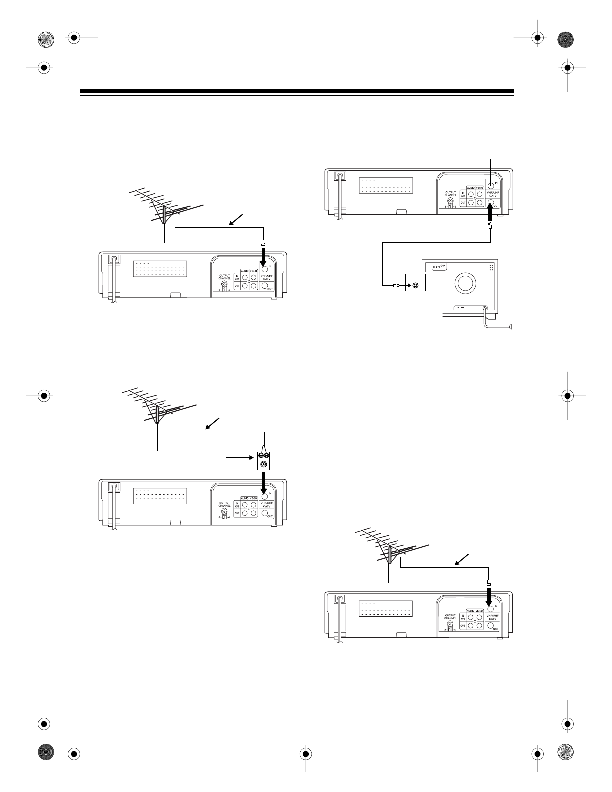
Connecting an Antenna
If you use an antenna only, connect the VCR to
the TV in one of these three ways:
• Using the TV’s audio/video input jacks (see
below)
• Using the TV’s single VHF/UHF F-connec tor (see Page 12)
• Using the TV’s single VHF F-connector
and double UHF screw terminals (see
Page 12)
Any of these connections lets you:
• Record and watch a channel you select
with the VCR’s tuner
• Watch a channel you select with the TV’s
tune r
• Record a channel you select with the
VCR’s tuner while you watch another
channel you select with the TV’s tuner.
Using the TV’s Audio/Video Input Jacks
If your antenna has 300-ohm lead-in wire,
you need to first convert it to a 75-ohm
cable by connecting a 300-to-75-ohm
matching transformer (such as Cat. No.
15-1253, not supplied) following these
steps.
300-Oh m Lead - In W ir e
300-to- 7 5-O hm
Matching Transformer
a. Connect the antenna’s lead-in wire to
the transformer’s 300-ohm input terminal screws.
b. C onnect the transformer’s 75-ohm out-
put F-connector to the VCR’s
CATV IN
input F-connector.
VHF/UHF
2. Use video quality shielded cables with
phono-type connections (such as Cat. No.
15-1538, not supplied) to connect the
VCR’s
AUDIO/VIDEO OUT
jacks to your
TV’s audio/video input jacks.
Note:
Do not use standard audio cables for
this connection.
1. If your antenna has 75-ohm cable, connect
the antenna cable directly to the VCR’s
VHF/UHF CATV IN
inpu t terminal.
75-Ohm Cab l e
11
Page 12
75-Ohm Cable
16-546.fm Page 12 Tuesday, July 20, 1999 4:25 PM
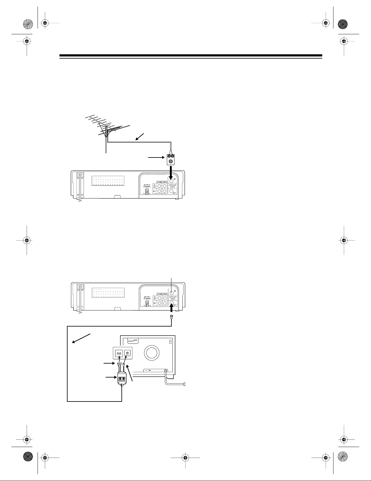
Using the T V’s
Singl e VHF/U H F F-Conn ector
1. If your antenna has 75-ohm cable, connect
the antenna cable directly to the VCR’s
VHF/UHF CATV IN
inpu t terminal.
75-Ohm Cab l e
If your antenna has 300-ohm lead-in wire,
you need to first convert it to a 75-ohm
cable by connecting a 300-to-75-ohm
matching transformer (such as Cat. No.
15-1253, not supplied) following these
steps.
300-Oh m Lead - In W ir e
300-to- 7 5-O hm
Matching Transformer
2. Use the supplied 75-ohm cable to connect
the VCR’s
VHF/UHF CATV OUT
F-connector
to your TV’s VHF/UHF antenna input Fconnector.
75-Ohm Cable
UHF VHF
VHF/UHF
VHF/UHF
Using the TV’ s
Single VHF F-Connector and
Double Scre w UH F Sc rew Terminals
If your TV has a single VHF F-connector and
double UHF screw terminals and your antenna
is not VHF-only (channels 2–1 3) or UHF-only
(channels 14–69), you need a band splitter
(such as Cat. No. 15-1231, not supplied) to
connect your VCR to the separate VHF and
UHF terminals.
a. Connect the antenna’s lead-in wire to
the transformer’s 300-ohm input terminal screws.
b. Connect t he transformer’s 75-ohm out-
put F-connector to the VCR’s
CA TV IN
input F-connector.
12
VHF/UHF
1. If your antenna has 75-ohm cable, connect
the antenna cable directly to the VCR’s
VHF/UHF CATV IN
inpu t te r mina l .
75-Ohm Cab l e
Page 13
y
y
16-546.fm Page 13 Tuesday, July 20, 1999 4:25 PM
If your antenna has 300-ohm lead-in wire,
you need to first convert it to a 75-ohm
cable by connecting a 300-to-75-ohm
matching transformer (such as Cat. No.
15-1253, not supplied) following these
steps.
300-Oh m Lead - In W ir e
300-to- 7 5-O hm
Matching Transformer
a. Connect the antenna’s lead-in wire to
the transformer’s 300-ohm input terminal screws.
b. Connect t he transformer’s 75-ohm out-
put F-connector to the VCR’s
CA TV IN
input F-connector.
VHF/UHF
2. Connect the band splitter’s 75-ohm input
cable to the VCR’s
VHF/UHF CATV OUT
ter-
minals.
3. Connect the splitter’s VHF 75-ohm F-c onnector to your TV’s single VHF input F-connector.
4. Connect the splitter’s UHF 300-ohm gold
wires to your TV’s double UHF input screw
terminals.
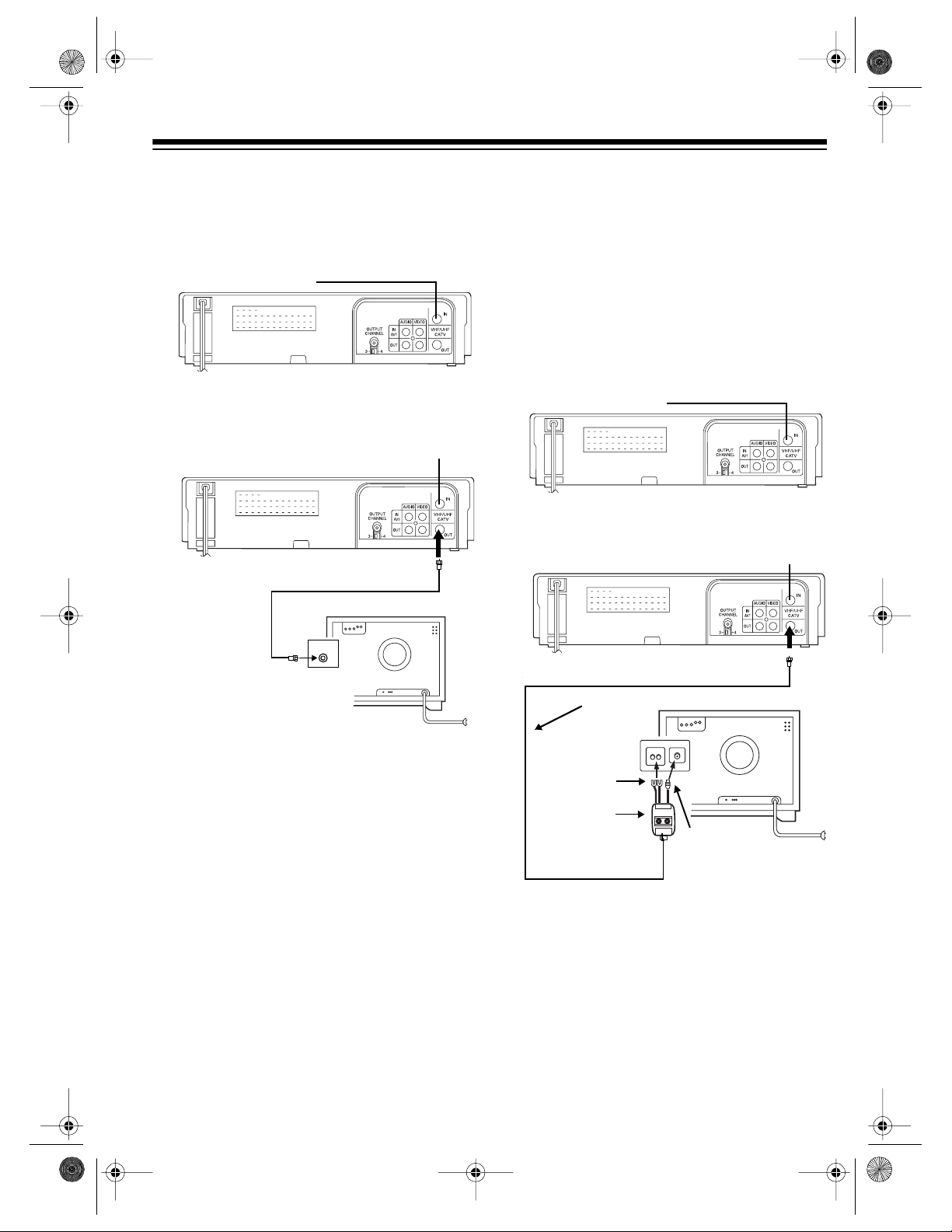
Connecting Cable
You can connect the VCR to cable with or without a cable box, then connect it to the TV in
one of these ways:
• To the TV’s audio/video input jacks (if it has
A/V jacks) (see Page 14)
• To the TV’s single VHF/UHF F-connector
(see Page 15)
• To the TV’s single VHF F-connector and
UHF double screw terminals (see Page 15)
• Using an A/B switch so you can record a
scrambled channel while you watch an
unscrambled channel (see Page 16)
Any of these connections let you:
• Record and watch a channel you select
with the VCR’s tuner.
• Watch a channel you select with the TV’s
tuner.
75-Ohm Cable
VHF/UHF
300-Ohm
UHF Output
Band Splitter
UHF VHF
75-Ohm
VHF Output
• Record a channel you select with the
VCR’s tuner while you watch another
channel you select with the TV’s tuner.
ou use cable but do not have a cable
If
box, and
casts
our TV can receive c able broad-
:
• You can watch and record any unscrambled channel.
• You cannot record scrambled channels.
13
Page 14
16-546.fm Page 14 Tuesday, July 20, 1999 4:25 PM
If you use a cable box:
• You m ust select channels using the c able
box.
• The cable box unscrambles premium cable
channels. To watch or record premium
channels, you must already subscribe to
them from your cable company.
Important: Some states have laws restricting
direct connections to cable wires (c onnections
that do not go through a cable box). Check the
laws in your area before you make connections.
Important Reminder to the CATV System Installer: You must comply with Section 820-40
of the National Electrical Code, which provides
guidelines for proper grounding and, in particular, specifies that the cable ground shall be
connected to the building’s grounding system,
as close to the point of cable entry as practical.
Using the TV’ s Audi o/Video
Input Jacks
1. Connect the CATV cable directly to the
VCR’s
VHF/UHF CATV IN
75-Ohm Cable
input terminal.
2. Use video quality shielded cables with
phono-type connections (such as Cat. No.
15-1538, not supplied) to connect the
VCR’s
AUDIO/VIDEO OUT
jacks to your
TV’s Audio/Video input jacks.
Note: Do not use standard audio cables for
this connection.
14
Page 15
75-Ohm Cable
16-546.fm Page 15 Tuesday, July 20, 1999 4:25 PM
Using the T V’s
Singl e VHF/U H F F-Conn ector
1. Connect the CATV cable directly to the
VCR’s
VHF/UHF CATV IN
75-Ohm Cable
inpu t te r mina l .
2. Use the supplied 75-ohm cable to connect
the VCR’s
VHF/UHF CATV OUT
F-connector
to your TV’s VHF/UHF antenna input Fconnector.
75-Ohm Cab le
Using the TV’ s
Single VHF F-Connector and
Double Scre w UH F Sc rew Terminals
If your TV has a single VHF F-connector and
double UHF screw terminals, you nee d a band
splitter (such as Cat. No. 15-1231, not supplied) to connect your VCR to the separate
VHF and UHF terminals.
1. Connect the CATV cable directly to the
VCR’s
VHF/UHF CATV IN
75-Ohm Cable
input terminal.
2. Connect the band splitter’s 75-ohm input
cable to the VCR’s
VHF/UHF CATV OUT
ter-
minals.
VHF/UHF
UHF VHF
VHF/UHF
75-Ohm Cable
VHF/UHF
300-Ohm
UHF Output
Band Splitter
3. Connect the splitter’s VHF 75-ohm F-c onnector to your TV’s single VHF input F-connector.
4. Connect the splitter’s UHF 300-ohm gold
wires to your TV’s double UHF input screw
terminals.
UHF VHF
75-Ohm
VHF Output
15
Page 16

16-546.fm Page 16 Tuesday, July 20, 1999 4:25 PM
Connecting an A/B Switch
and a Si gnal Splitter
You can record a scrambled channel and
watch an unscram bled one u sing a high-isol ation A/B switch (such as Cat . No. 15-124 9, not
supplied) and a hybrid splitter/combiner (such
as Cat. No. 15-1141, not supplied).
Notes:
• This connection requires up to four additional 75-ohm coaxial cables (such as Cat.
No. 15-1529, not supplied).
• You cannot record scrambled channels
without using a cable box.
• You c an record a scrambled channel while
you watch an unscrambled channel.
Cable Box
To TV’s
VHF/UHF
Terminals
UHF VHF
Out
A B
A/B Switch
1. Connect the CATV cable to the band splitter’s 75-ohm input.
6. Connect another 75-ohm cable between
the A/B switch’s output terminal and your
TV’s VHF/UHF input terminal.
Note: If your TV has separat e VHF/UHF terminals, connect the cable to the TV’s VHF terminal only.
SETTING THE OUTPUT
CHANNEL SWITCH
OUTPUT CHANNEL
Set
VCR) to
3
or 4, whichever is not an active chan-
nel in your area.
When you use the VCR, it sends its output signals to the TV on the channel you selected.
OUTPUT CHANNEL
Note:
TV when the VCR is off or if you are using a TV
that has separate audio/video input jacks and
you set the TV to the video mode.
(on the back of the
has no effect on the
2. Connect the supplied 75-ohm cable
between one of the splitter’s output terminals and the A/B switch’s A input terminal.
3. Connect another 75-ohm cable between
the splitter’s other output terminal and the
cable box’s input terminal.
4. Connect another 75-ohm cable between
the cable box’s output terminal and the
VCR’s
VHF/UHF CATV IN
terminal.
5. Connect another 75-ohm cable between
the VCR’s
VHF/UHF CATV OUT
terminal
and the A/B switch’s B input terminal.
16
CONNECTING POWER
When you complete all other connect ions, plug
the VCR’s power cord into a st andard AC out-
– –:- -
let.
flashes on the display.
Page 17

16-546.fm Page 17 Tuesday, July 20, 1999 4:25 PM
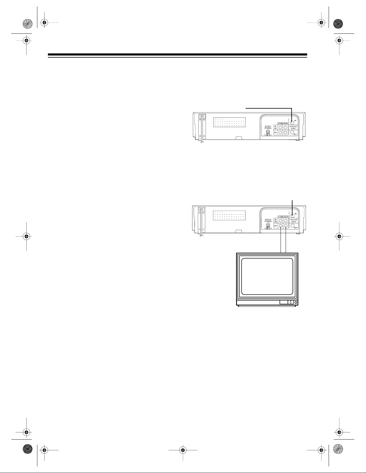
PREPARATION
USING THE REMOTE
CONTROL
Installing the Batt eries
To power the remote control, you need two AA
batteries (not supplied). For the best performance, use alkaline batteries (such as RadioShack Cat. No. 23-557).
Cautions:
• Use only fresh batteries of the required
size and type.
• Never leave dead batteries in the remote
control.
• Dispose of dead batteries promptly and
properly; do not bury or burn them.
Follow these steps to install batteries.
A Quick Look at the Controls
VIDEO CASSETTE RECORDER
MODEL 109
POWER
ON SCREEN
DISPLAY
MENU
TAPE SPEED
EJECT
123
456
CH
78
AM/
100/
CH
RECORD
REW
PM
SET
PLAY
STOP
SLOW
TV/VCR
0
MODE LOCK
9
INPUT
ZERO BACK
CANCEL
PAUSE
/STILL
FF
DPSS
1. Press down on the battery compartment
cover and slide it in the direction of the
arrow to remove it.
2. Insert fresh batteries into the compartment,
as indicated by the polarity symbols (+ and
–) marked inside the compartment.
3. Replace the cover.
If the remote control does not work or
Note:
operates poorly, replace both batteries.
You can control most of the VCR’s normal operations using the buttons on either the VCR or
the remote control. However, for some features, you must use the remote control. The instructions in this manual mention only the
remote control’s buttons. The corresponding
buttons on the VCR are shown in the following
table.
17
Page 18

16-546.fm Page 18 Tuesday, July 20, 1999 4:25 PM
Remote Control VCR Function
POWER POWER
EJECT STOP/
EJECT
STOP/ STOP/
EJECT
TV/VCR
Turns the VCR’s power on/off.
If a tape is playing
•Pressing
:
EJECT
on the remote control automatically
stops playing a video tape, then ejects the cassette).
•Pressing
STOP/ EJECT
on the VCR once stops
playing a video cassette tape, twice ejects the cassette.
If a tape is not playing, pressing
control or
STOP/ EJECT
on the VCR ejects the cas-
EJECT
on the remote
sette.
STOP
•
— Stops playing a video cassette tape.
• — Moves the highligh ting down while the menu is
displayed.
• If a tape is playing
,
pressing
STOP/ EJECT
stops playing a video cassette tape, twice ejects the
cassette.
• If a tape is not playing, pressing
STOP/ EJECT
ejects the cassette.
Selects either the TV’s or VCR’s tuner.
once
MODE LOCK
ON SCREEN
DISPLAY
CH CHANNEL
18
Locks in any selected operating mode (see “Mode Lock”
on Page 32).
Displays the VCR’s current modes (see “Operation Displays” on Page 27).
• When a tape i s not playing, selects the VCR’s display
and alternates between the tuned channel, the tape’s
elapsed playing time, and the currently set time of
day.
• When a tape is playing, selects the VCR’s display and
alternates between the tape’s elapsed playing time
and the currently set time of day.
• Tunes the VCR to the next higher channel.
• Reduces or eliminates jitter in a slow-motion picture
(see “Variable Speed Slow Motion” on Page 29).
• Manually adju sts the tracking (see “Manua l Tracking”
on Page 31).
Page 19

16-546.fm Page 19 Tuesday, July 20, 1999 4:25 PM
Remote Control VCR Function
CH CHANNEL
Numbers
100
INPUT
ZERO BACK
MENU MENU
SET SET
1-0
AM/
PM
• Tunes the VCR to the next lower channel.
• Reduces or eliminates jitter in a slow-motion picture
(see “Variable Speed Slow Motion” on Page 29).
• Manually adju sts the tracking (see “Manua l Tracking”
on Page 31).
Directly selects a channel, or enters other programming
values.
100 —
•
•
Selects channels 100 and larger.
AM/
—
Selects AM or PM when you are setting the clock
PM
and programming modes.
Selects either the
VHF/UHF
AUDIO/VIDEO
or
input jacks as
the recording source.
Rewinds the tape to the point where the elapsed time
reads 0:00.0.
Displays the main menu on the TV’s screen for about 60
seconds.
Once you select the desired function from the main menu,
pressing
Note:
SET
enters that function.
You can use
SET
only while the main menu appears
on the TV’s screen.
CANCEL
RECORD RECORD
PLAY/ PLAY
PAUSE
/STILL
PAUSE
/STILL
Resets the tape elapsed playing time to 0:00.0.
Starts recording on a video cassette tape.
PLAY
•
•
PLAY
(remote control) — Plays video cassette tape.
(VCR front panel) — Plays video cassette tape.
• — Moves the highlighting up while the m enu is displayed.
PAUSE
•
— temporarily stops playing a tape and contin-
ues to show the still image of the recording.
STILL
•
— advances the image one frame at a time.
19
Page 20

16-546.fm Page 20 Tuesday, July 20, 1999 4:25 PM
Remote Control VCR Function
/
REW
(Shuttle Dial)
REW
•
— quickly rewinds a video cassette tape if
the tape is stopped. Does not show a picture on the
TV screen.
• — quickly plays a cassette tape backward so you
can find a desired section of a recording.
• — Moves the highlighting left while the menu is displayed.
• Rotate the VCR’s shuttle dial counterclockwise to
select for rewinding. The shuttle dial automatically returns to its center position when you release it.
FF /
T APE SPEED
SLO W
DPSS
(Shuttle Dial)
•
— quickly plays a cassette tape forward so you
can find a desired section of a recording.
FF
•
— quickly advanc es a video cassette tape if
the tape is stopped. Does not show a picture on the
TV screen.
• — moves the highlighting right while the menu is
displayed.
• Rotate the VCR’s shuttle dial clockwise to select
for fast-forwarding. The shuttle dial automatically returns to its center position whenever you
rel ease it.
Selects the SP or EP tape speed.
Starts slow-motion playback during normal playback,
freeze-frame, quick-motion, or visual search.
• During slow-motion play, varies the slow-motion playback speed (forward or reverse) from
1
/30 to 1/5 of the
normal playback speed.
• During normal play, skips forward or backward to the
next recording on a tape (see “Index Search” on Page
31).
20
AUTO
ENHANCED
PICTURE
Automatically enhances picture quality during playback.
Page 21

16-546.fm Page 21 Tuesday, July 20, 1999 4:25 PM
For the best results, ai m the remote con trol’s
signal emitter (on the remote c ontrol’s top end)
toward the VCR’s display, and press the desired function button(s).
FOUR HEAD
19 MICRON ENHANCED EP IMAGING
MODE LOCK
9
ZERO BACK
CANCEL
DPSS
INPUT
AUTO ENHANCED
PICTURE
PAUSE
/STILL
FF
MEMORY SENTINEL
VIDEO CASSETTE RECORDER
MODEL 109
POWER
EJECT
123
ON SCREEN
DISPLAY
456
CH
78
AM/
100/
PM
CH
MENU
SET
RECORD
REW
TAPE SPEED
SLOW
TV/VCR
0
PLAY
STOP
SETTING THE ON-SCR EEN
PROGRAMMING LANGUAGE
1. Press
2. If you connected the VCR to your TV’s
3. If you connected the VCR to your TV’s
POWER
.
SP
audio/video input jacks, proceed directly to
Step 3.
If you connected the VCR to you r TV’s single VHF/UHF F-connector or its separate
VHF and UHF screw terminals, turn on
your TV and tune it to the same channel
you set the VCR’s
OUTPUT CHANNEL
switch to (3 or 4).
audio/video input jacks, set the TV to the
VIDEO or AUX mode.
If you connected the VCR to you r TV’s single VHF/UHF F-connector or its separate
VHF and UHF screw terminals, press
VCR
so
VCR
appears on the VCR’s display.
TV/
4. Press
MENU
the TV screen.
MENU
TIMER
SET UP
CHANNEL PRESET
CLOCK
LANGUAGE
SELECT :
ENTER :SET EXIT :MENU
SP VCR
to display the main menu on
21
Page 22

S
16-546.fm Page 22 Tuesday, July 20, 1999 4:25 PM
Note: If you have not selected a language
since you connected power, the language
setting menu automat ically appears on the
TV screen when you p ress
MENU
. Skip to
Step 6.
5. Repeatedly press or until
LANGUA GE
is highlighted on the displayed menu. Then
SET
press
.
MENU
TIMER
SET UP
CHANNEL PRESET
CLOCK
LANGUAGE
SELECT :
ENTER :SET EXIT :MENU
6. Repeatedly press or until the language you want, , ,
or , is highlighted, then press
FRANCAI
SET
. The VCR stores the language you
ENGLISH ESPANOL
selected and the menu disappears.
LANGUAGE
ENGLISH
ESPANOL
FRANÇAIS
SETTING THE CLOCK
Notes:
• If you enter an invalid date or time (for
example, 55 for the date), the VCR does
not accept nor record the entry and the display returns to the previous setting. Reenter the correct date or time.
• During the setting procedure, you can
press or to advance or go back one
setting. Press and hold either button to
advance rapidly. However, once you use
the remote control’s number buttons,
pressing or returns the data to the
original setting.
• You can also use the front panel shuttle
dial to move to another setting: rotate it
clockwise to advance t o the next item, or
counterclockwise to return to the previous
item.
• The VCR’s memory sentinel feature protects the clock and your automatic and
quick timer recording settings for up to 1
hour in case a power failure occurs or the
power cord is temporarily unplugged.
1. Press
2. Repeatedly press or until
MENU
to display the main menu.
CLOCK
highlighted, then press
ting menu appears on the TV screen.
SET
. The clock set-
is
SELECT :
ENTER :SET EXIT :MENU
Each time you press
MENU
ON SCREEN
or
,
CLOCK
TIME DATE YEAR DST
10:28AM 1/01MON 96 ON
the displays on t he TV’s screen appear in
the selected language.
SELECT : CHANGE:
ENTER :SET EXIT :MENU
22
Page 23

POWER
ON SCREEN
DISPLAY
CH
CH
INPUT
EJECT
123
456
78
100/
0
9
TV/VCR
MODE LOCK
ZERO BACK
AM/
PM
16-546.fm Page 23 Tuesday, July 20, 1999 4:25 PM
3. Use the number keys to enter the correct
time (hour and minute), then press
to select AM or PM.
For example, to set 10:28 AM, press
2
, and 8, th en press
The VCR accepts the last three or
Note:
AM/
100
/ to select AM.
PM
four valid entries as the time. Fo r ex amp le,
1, 3, 3
if you enter
, and 5, the VCR stores it
as 3:35.
DATE
4. Press to highlight
. Then use the
number keys to enter the correct date
(month and day). For example, to set February 15, press
The day of the week is automatically
Note:
0, 2, 1
, and 5.
set; however, it might be temporarily incorrect if the year is not set yet.
YEAR
5. Press to highlight
. Then use the
number keys to enter the last two digits of
the current year. For example, to set 19 96,
9
press
6. Press to highlight
and 6.
DST
. To set daylight
saving time (DST), press or so
appears on the display.
DST
When you set
to ON, the VCR automatically adds one hour to all the displayed
times starting from the first Sunday in April,
and subtracts one hour from all displayed
times on the last Sunday in October.
7. If the information you entered is not correct, repeatedly press or to move the
cursor to the incorrect information, then
enter the correct information.
If the information you entered is correct,
SET
press
. The screen disappears.
100
/
1, 0
ON
SETTING THE CHANNELS THE
AM/
PM
VCR TUNES TO
You can have the VCR automatically store all
active channels in your area into its memory,
and you can add to or remove the stored channels.
1. Turn on your TV and VCR.
MENU
2. Press
to display the main menu.
3. Press twice to highlight
,
PRESET
set menu appears.
, then press
SET
. The channel pre-
4. Select the input signal source (
CATV
).
— If you connected an antenna or
AIR
cable without a cable box to the VCR,
AIR
press or so
is highlighted, then
press so an arrow appears next to
SET
.
CHANNEL PRESET
AIR/CATV AIR CATV
CH SET AUTO MANUAL
SELECT : CHANGE:
ENTER :SET EXIT :MENU
— If you connected cable and use a
CATV
cable box:
a. Pres s or until you highlight
then press .
b. Pres s or to highlight the type cable
you have (
Note:
Most cable systems use NOR-
NORMAL, HRC
, or
MAL, but if you are not sure what type
of cable service you have, contact your
cable company.
c. Press so an arrow appears next to
SET
.
CHANNEL
AIR
or
CH
CATV
IRC
).
CH
,
23
Page 24

16-546.fm Page 24 Tuesday, July 20, 1999 4:25 PM
5. Press or to highlight
UAL
, then press
CHANNEL PRESET
AIR/CATV AIR CATV
CATV NORMAL HRC IRC
CH SET AUTO MANUAL
SELECT : CHANGE:
ENTER :SET EXIT :MENU
AUTO
— The VCR’s tuner automatically
SET
AUTO
or
.
scans through the channels (TV or CATV)
and memorizes the active channels in yo ur
area.
AUTOMAT- TUN- PLEAS WAI
and the current channel number appea r on
the TV screen, and
CH
and the current
channel appear on the VCR’s display. After
scanning all the channels, the tuner stops
on the lowest-numbered stored channel.
MANUAL
—
ADD
or
ERASE
and the current channel appear on the upper right corner of the TV screen.
a. To change the channels one at a time
(higher or lower), press or .
To directly select chann els, use the re-
mote control’s number buttons. See
“Selecting Channels” on Page 25.
b. To add the channel to memory, press
ADD
or so
appears to the left of the
selected channel.
To delete the channel from memory,
press or s o
DELETE
appears to
the left of the selected channel.
MAN-
• While you manually set a channel,
the TV screen turns green and does
not show the received broadcast signals.
Adding/Erasing Channels
You can add a channel that is not already
stored, or erase an unwanted stored channel.
1. Press
2. Press twice to highlight
3. Press to highlight
4. Press or to highlight
5. Repeatedly press or (or use the num-
6. Repeatedly press or so
MENU
to display the main menu.
CHANNEL
PRESET
, then press
set menu appears on the TV screen.
SET
press
.
ber keys) so the channel num ber you want
appears on the display.
Notes:
• Precede a single-digit number with a
— for example, 01, 02, etc.
• To enter a three -digit num ber, press
then enter the second and third digits in
the channel number.
ERASE
appears in the upper right corner
of the TV screen, then press
ADD 03
SET
. The channel pre-
CH SET
.
MANUAL
SET
.
, then
ADD
100
or
0
,
c. Repeat Steps a and b until you store all
the channels you want.
Notes:
• You c an repeatedly press or to
review the stored channels.
24
7. Press
CHANNEL SELECT :
ADD/ERASE :
EXIT :MENU
MENU
to return to the normal screen.
Page 25

16-546.fm Page 25 Tuesday, July 20, 1999 4:25 PM
BASIC OPERATION
W ATCHING TV
Using the TV’s Tuner
1. Turn off the VCR, or press
disappears from the VCR’s display.
2. Set the TV to the TV mode.
The antenna or cable signals pass throug h the
VCR unaffected, as if the antenna or cable
were connected directly to the TV.
TV/VCR
Using the VCR’s Tuner
1. Press
VCR’s display.
2. If you connected the VCR’s
OUT
input jacks, set the TV to the VIDEO mode.
If you connected the VCR’s
OUT
UHF input F-connector or separate VHF Fconnector and UHF input screw terminals:
a. Set the TV to the same channel (3 or 4)
b. Set the TV to the TV mode.
TV/VCR
jacks to a TV/monitor’s audio/video
jacks to a TV/monitor’s single VHF/
OUTPUT CHANNEL
as
until
VCR
appears on the
AUDIO/VIDEO
AUDIO/VIDEO
.
so
VCR
Selecting Channels
Your VCR can receive up to 68 VHF and UHF
channels, and up to 125 cable channels. The
VCR displays the channels as 1–125.
Notes:
• Channels 2–13 are the same for VHF and
cable TV, and cable companies usually
number them as they appear on the display.
• Since cable companies sometimes designate cable channels with letters or letternumber combinations, a channel number
you see on the VCR’s display might differ
from the channel number displayed on
your cable box. You might need to experiment to determine the proper ca ble channel designations for your cable system. For
more information, contact your local cable
compa ny.
To change the channel, press
The tuner changes to the next higher or lower
channel stored in its memory.
If you press
Note:
the highest programmed channel or
when the tuner is at the lowest programmed
channel, the VCR enters the audio/video mode
AV
and
ue to press
lowest programmed channel appears.
appears on the V CR’s display. Contin-
CH
CH
when the tuner is at
CH
or
CH or CH
CH
until the highest or
.
To directly select a channel, press the number
buttons on the remote control for the desired
channel.
Notes:
• Always precede single-digit numbers with
a 0 — for example, 01, 02, etc.
• To enter a three-digit number, first press
100
then enter the second and t hird digits
of the channel number.
25
Page 26

16-546.fm Page 26 Tuesday, July 20, 1999 4:25 PM
W ATCHING A VIDEO TAPE
Loading a Video Tape
Insert the video cassette into the VCR’s compartment with the label facing up an d the tape
swivel-cover facing into the compartment. Gently push in the cassette until the VCR automatically draw s it in.
Caution:
video cassette into the cassette compartment.
You might damage the VCR’s internal mechanism.
When you load a t ape that still has its recordprotection tab (see “Record Protection” on
Page 34), the VCR positions the tape next to
the record/playback head for about 5 minutes.
Within this period, if you start playback, recording, rewind, or fast-forward, the VCR responds
more quickly.
When you stop the tape during playback, rewind, or fast-forward, the tape remains positioned next to the record/playback head for
about 5 minutes. To protect the t ape, the fastresponse system releases after about 5 minutes.
Never insert anything except a VHS
If you connected the VCR’s
OUT
jacks to a TV/monitor’s single VHF/
AUDIO/VIDEO
UHF input F-connector or separate VHF Fconnector and UHF input screw terminals:
a. Set the TV to the same channel (3 or 4)
OUTPUT CHANNEL
as
.
b. Set the TV to the TV mode.
3. If playback does not automatically begin,
PLAY
press
Note:
.
During playback, the VCR automatically adjusts the tracking. However, you
can also manually adjust it (see “Manual
Tracking” on Page 31).
4. To stop playback before the end of the tape
EJECT
and eject the tape, press
VIDEO CASSETTE RECORDER
MODEL 109
POWER
ON SCREEN
DISPLAY
CH
EJECT
TV/VCR
123
456
78
.
MODE LOCK
9
Playing a Video Tape
1. Load a video tape.
Note:
If the record-protection tab has been
removed from the tap e, t he VCR automatically turns on, the clock display changes to
the tape counter, and playback automatically begins (see “Record Protection” on
Page 34).
2. If you connected the VCR’s
OUT
jacks to a TV/monitor’s audio/video
input jacks, set the TV to the VIDEO mode.
26
AUDIO/VIDEO
Notes:
• If the video tape reaches the end before
you press
EJECT
, the VCR automatically
stops the tape, completely rewinds it,
ejects the cassette, then turns itself off.
• When the VCR is off, you can press
EJECT
to eject a tape. The VCR turns
itself on, ejects the tape, then turns itself
off.
Page 27

16-546.fm Page 27 Tuesday, July 20, 1999 4:25 PM
SPECIAL FUNCTIONS
DISPLAYS
Blue Screen
The blue-screen display appears on the TV
screen when the VCR does not send a signal
to the TV from either the
terminal or the
as:
• When you play unrecorded portions of a
tape
• When you tune the VCR to an unused
channel
Note:
screen.
Follow these steps to turn t he blue screen on
or off.
The VCR does not record the blue
1. Press
VCR’s display.
2. Press
AUDIO/VIDEO OUT
TV/VCR
MENU
so
to display the main menu.
VHF/UHF CATV OUT
jacks, such
VCR
appears on the
Operation Di spla ys
• Each time you press
VCR’s current operating information
appears on the TV screen in this
sequence:
PLAY, STOP, FF
a.
(if a cassette is inserted)
AUTO EN HA NC E ON
Auto Re pe at ON
Tape speed (SP,
Channel
Date and Time
Tape counter
b. Counter only
c. No display
d. Tape mode and/or the tuned channel for
about 3 seconds
• When you press a function button (such as
STOP
), the corresponding indicator
appears on the TV screen for about 3 seconds.
ON SCREEN
REW
, or
or
or
EP
)
, your
OFF
OFF
3. Press to highlight
SET
. The set up menu appears.
4. Press or to select
5. Press or to highlight
SET
6. Press
.
SET UP
BLUE SCRE EN
, then press
ON
or
OFF
• When you change the channel, the channel number appears on the T V screen for
.
.
about 3 seconds.
If you play back a poor quality (worn) or
Note:
damaged tape, the funct ion indicator or channel number might not appear on the TV.
Auto Display
When you press an operation button (
RECORD, STOP
number button, or
operating mode or a channel number appears
on the TV screen for about 3 seconds
FF
,
CH or CH ,
, or
PLAY
),
REW
the current
.
,
a
27
Page 28

ZERO BACK
CANCEL
MENU
RECORD
PAUSE
/STILL
PLAY
REW
FF
STOP
SET
16-546.fm Page 28 Tuesday, July 20, 1999 4:25 PM
Tape Motion Indicators
Any time a cassette is loaded in the com partment, appears on the VCR’s display
whether power is on or off.
The tape motion indicators on t he VCR’s display show you the current operating mode and
the tape’s playback direction.
Indicator Mode
Play
REC
Record
Slow-Motion
Freeze-Frame
Frame Advance
Fast-Forward/
Forward Visual Search
Rewind/
Reverse Visual Search
To rewind the tape quickly when it is stopped,
press
(or turn the shuttle dial on the
REW
VCR fully counterclockwise, then release it).
Note:
You cannot watch the tape’s video or
hear the tape’s sound while you fast-forward or
rewind the tape.
Freeze-Frame
Freeze-frame lets you watch the tape a single
frame at a time.
To freeze the tape during playback, press
PAUSE
.
/STILL
To advance the tape on e frame at a time, repeatedly press .
To return to the normal playback speed, press
PLAY
.
Notes:
• You can also visual search backward or
forward from the freeze-frame mode (see
“Visual Search” on Page 29).
PAUSE
/STILL
MOTION CONTROLS
Fast-Forward/Rewind
To advance the tape quickly when it is stopped,
FF
press
VCR fully clockwise).
Caution:
rotate 360°. Do not force it past the point where
it stops.
28
(or turn the shuttle dial on the
The shuttle dial on the VCR doe s not
• Depending on the tape speed used for
recording, the freeze-frame might have
reduced picture quality.
• To protect the tape, if you leave the VCR in
the freeze-frame mode for 5 minutes, the
VCR automatically returns to normal playback.
• If a horizontal “noise” bar appears during
freeze-frame, adjust the tracking in the
slow-motion mode (see “Variable-Speed
Slow Motion” on Page 29).
Page 29

CH
INPUT
78
100/
0
9
ZERO BACK
CANCEL
MENU
RECORD
PAUSE
/STILL
PLAY
REW
FF
STOP
SET
AM/
PM
CANCEL
MENU
RECORD
PAUSE
/STILL
PLAY
REW
FF
STOP
SET
CANCEL
MENU
RECORD
PAUSE
/STILL
PLAY
REW
FF
STOP
SET
16-546.fm Page 29 Tuesday, July 20, 1999 4:25 PM
Visual Search
Visual search lets you play a tape at a faster
speed (either forward or backward) so you can
search for a specific s ection of the tape. You
can select normal or fast visual search speeds.
For normal visual search speed, during playback, press
the shuttle dial on the VCR clockwise or counterclockwise about halfway).
For fast visual search speed, during normal
visual search press
tle dial on the VCR fully clockwise or counterclockwise).
or once (or turn and hold
or (or turn the shut-
Variable-Speed Slow Motion
You can play a tape in slow-motion and vary
the slow-motion speed.
To start slow-motion playback, during playback, freeze-frame, or visual search, press
SLOW
. The tape plays at 1/10 of the normal
playback speed.
Press
SLOW
to increase, or
crease the slow-motion playback speed.
SLOW
to de-
To stop visual search and return to normal
playback, press
PLAY
.
Notes:
VCR
must appear on the VCR’s display to
•
use visual search. If it does not, press
VCR
so
VCR
appears.
TV/
• During visual search, the sound is muted
and the picture quality is lower than during
normal playback. The search picture is
best with tapes recorded at the EP speed.
PLAY
Press
to resume normal playback.
Notes:
• The slow motion picture i s best with tapes
recorded at the EP speed.
• During slow motion, the sound is muted.
• To protect the VCR’s heads, if you leave
the VCR in slow-motion play for 5 minutes ,
the VCR automatically returns to normal
playback.
• To reduce or eliminate jitter in a slowmotion picture, press , then press
and hold down
CH or CH
PAUSE
/STILL
until the pic-
ture is clear.
29
Page 30

16-546.fm Page 30 Tuesday, July 20, 1999 4:25 PM
Automat ic Repeat Pla yback
You can set the VCR to automatically repe at a
recorded portion of a tape when the VCR finds
a blank portion of more than 15 seconds.
Follow these steps to turn automatic repeat
playback on or off.
1. Press
2. Press to highlight , then press
3. Press or to highlight
MENU
to display the main menu.
SET UP
SET
. appears on the TV
AUTO REPEAT
screen.
AUTO REPEAT ON OFF
BLUE SCREEN ON OFF
CHANNEL PRESET
SELECT : CHANGE:
ENTER :SET EXIT :MENU
ON
or
desired.
If you turn on automatic repeat play-
Note:
back:
OFF
as
USING THE REAL-TIME
COUNTER
Your VCR’s real-time counter shows how long
(in hours, minutes, and seconds) a tape has
been running.
To display the real-time counter, press
PLAY
on the remote control so the counter ap-
pears on the VCR’s display.
To reset the counter to
CEL
.
0:00:00
, press
Notes:
• If you rewind the tape past
0:00.00
display shows the count with a minus (–)
sign.
• The counter does not work with blank
tapes or blank portions of partially
recorded tapes.
• The counter also resets when you remove
a tape.
DIS-
CAN-
, the
• Any tape will play until the VCR finds a
non-recorded portion of more than 15
seconds, then automatically rewinds and
plays again.
• If you press
and the tape
REW
reaches the beginning, playback automatically starts.
SET
4. Press
. The display returns to the n or-
mal screen.
30
Using the Zero Back Function
At any time during playback, you can reset the
real-time counter to
that position.
1. During playback, press
remote control to display the real-time
counter.
2. When you see the location on the tape that
you want to return to later, press
on the remote control. The real-time
counter resets to
3. To return to the
later time during playback, press
BACK
. The tape automatically rewinds or
fast-forwards to the
0:00.00
0:00.00
0:00.00
0:00.00
, the n return to
DISPLAY
on the
CANCEL
.
location at a
ZERO
location.
Page 31

ZERO BACK
CANCEL
MENU
RECORD
PAUSE
/STILL
PLAY
REW
FF
STOP
SET
DISPLAY
CH
CH
INPUT
456
78
100/
0
9
ZERO BACK
CANCEL
MENU
RECORD
PAUSE
/STILL
PLAY
SET
AM/
PM
16-546.fm Page 31 Tuesday, July 20, 1999 4:25 PM
INDEX SEARCH
Your VCR has the Digital Program Search System (DPSS). Each time y ou start recor d ing, the
VCR automatically marks the t ape with an index signal.
You can use index search to:
• Return to the beginning of the current
recording.
• Skip to the beginning of the next recording.
• Locate a specific recording, if there are
several recordings on a tape.
The VCR can search through up to 19 index
signals.
DPSS
Each time you press
or , the VCR
finds the next index signal and automatically
starts playback.
Notes:
• The only way to add an index signal to a
tape is to start a new recording.
• The only way to remove an index signal is
to record over it.
AUTO TRACKING
The VCR automatically adjusts tracking when
you play a tape.
screen while the VCR is adjusting the tracking.
PLAY
flashes on the TV
Note:
To make it easier to locate a particular
recording, we recommend you list the real time
counter reading on the tape’s label each time
you start a recording.
While the VCR is stopped or during playback,
on the remote control repeatedly press
(to search forward) or
DPSS
(to search back-
DPSS
ward) the same number of times as the number
of recordings you want skip.
For example, if the tape is at recording 2 and
DPSS
you want to watch recording 8, press
6
times to skip the remaining portion of recording
2 and recordings 3 through 7. Or, if the tape i s
at recording 9 and you want to watch recording
4, press
DPSS
6 times (to s kip past record-
ings 9 through 5).
When different parts of the tape are recorded
at different speeds, the VCR automatically readjusts the tracking at the beginning of each
recording.
Manual Tracking
If the VCR’s picture is poor while playing a
tape, press and hold down either
to manually adjust the tracking.
To return to automatic tracking, press
CH
and
Note:
at the same time.
When you eject a tape or turn on the
VCR, the VCR resets to auto tracking and
erases any manual tracking adjustment you
made.
CH or CH
CH
31
Page 32

16-546.fm Page 32 Tuesday, July 20, 1999 4:25 PM
AUTO ENHANCED PICTURE
Your VCR automatically enhances the picture
quality during playback.
The auto enhanced picture function is set to
at the factory. Normally leave it set to on. When
you play a tape for editing or when strong noise
appears on the screen, set it to
During normal playback, press
HANCED PICTURE
on the VCR’s front panel to
OFF.
AUTO EN-
turn the auto enhan ce picture f eat ure o n or off.
AUTO ENHANCE ON
(or
) appears briefly
OFF
on the TV screen.
ON
MODE LOC K
You can lock in any selected operating mode
on the VCR (including power off) to prevent accidentally changing to another mode or to prevent young children from operating the VCR.
All modes remain locked until you release the
lock using the remote control.
Note:
tape from freeze-frame and record/pause when
mode lock is turned on.
To turn on mode lock, press and hold down
MODE LOCK
lights steadily on the VCR’s display.
The VCR still automatically releases a
on the remote control until
VIDEO CASSETTE RECORDER
MODEL 109
POWER
ON SCREEN
EJECT
TV/VCR
MODE LOCK
123
DISPLAY
456
CH
78
100/
CH
AM/
PM
9
0
INPUT
If you press any button on the VCR or remote
control (except
MODE LOCK
), flickers and
the button does not function. If you try to load a
tape, the VCR draws it in and then ejects it.
To release mode lock, press and hold down
MODE LOCK
until disappears.
32
Page 33

16-546.fm Page 33 Tuesday, July 20, 1999 4:25 PM
RECORDING
You can make the following types of recordings
with your VCR.
• Immediate recording
• Quick timer recording
• Automatic timer recording
• Dubbing
Notes:
• Your VCR records the audio signal and
automatically adjusts the sound level while
it records.
• The video tape you use fo r recording mus t
have the record-protection tab in pla ce. If
the tab is removed, the VCR automatically
ejects the tape if you try to record on it (see
“Record Protection” on Page 34).
RECORDING SPEEDS
(Short Play) Playback/Record — This is the
SP
fastest recording speed and results in the highest quality picture. However, this speed uses
the most tape.
TAPE SELECTION
The quality of tape you use greatly affects
record/playback quality and the life of the VCR.
Use only VHS video cassettes. High-grade
tape has a better oxide coating that helps prevent dirty video heads and gives the best results .
Although T-160 video cassettes offer the longest recording time, they contain thinner tape
that is more likely to jam. We recommend you
use T-120 or shorter length tape.
The following chart shows the maximum recording times for different-length tapes at the
two recording speeds.
Recording Time
Tape
SP EP
T-60 60 minutes 180 minutes
T-120 120 minutes 360 minutes
T-160 160 minutes 480 minutes
(Long Play) Playback only — Your Model
LP
109 VCR can p lay but can not record at t he LP
speed.
(extended play) Playback/Record — This
EP
records more slowly and uses less tape, but
the picture quality is not as high as w ith a recording made at the SP speed.
However, the Model 109 VCR has a special
19-micron record/play head that improves the
playback quality of recordings made at the EP
speed. This lets you conserve tape when recording and still enjoy a high quality picture
during playback.
33
Page 34

16-546.fm Page 34 Tuesday, July 20, 1999 4:25 PM
RECORD PROTECTION
Video cassettes have a record protection tab.
With the tab in place, you can record on the
tape.
To help prevent acciden tally recording over a
recording, break off the tab using a screwdriver. With the tab removed, you cannot record
over a tape. The cassette aut omatically ejects
if you try to record on the tape.
SELECTING THE SIGNAL TO
RECORD
To record from the VCR’s VHF/UHF signals,
INPUT
press
a channel number appear on the TV screen
and the VCR’s display.
To record from the VCR’s
jacks, press
screen and the VCR’s display.
on the remote control until CH and
SP
AUDIO/VIDEO IN
INPUT
until AV appears on the T V
SP VCR
Caution:
Removing the record-protection tab
does not prevent a bulk tape eraser from erasing a cassette.
If you are sure you want to record on a video
cassette that has ha d i ts tab rem oved, plac e a
piece of heavy plastic tape over the record protection tab hole.
34
Page 35

16-546.fm Page 35 Tuesday, July 20, 1999 4:25 PM
IMMEDIATE RECORDING
Note:
If you want to record from another VCR,
a laser disc player, or other audio/video source
with A/V outputs, see “Dubbing (Copying) a
Tape” on Page 40.
Recording a Program As You
Watch It
1. If you connected the VCR’s
OUT
jacks to a TV/monitor’s audio/video
input jacks, set the TV to the VIDEO mode.
If you connected the VCR’s
OUT
jacks to a TV/monitor’s single VHF/
UHF input F-connector or separate VHF Fconnector and UHF input screw terminals:
a. Press
TV/VCR
until
VCR’s display.
b. Set the TV to the TV mode.
c. Set the TV’s tuner to the same channel
as the VCR’s
OUTPUT CHANNEL
If you are using an A/B switch:
AUDIO/VIDEO
AUDIO/VIDEO
VCR
appears on the
switch.
Notes:
• Yo u can press during recording
PAUSE
/STI LL
to temporarily pause recording (during
commercials, for example). To resume
recording, press again o r press
RECORD
.
PAUSE
/STI LL
• If you pause the VCR for about 5 minutes while recording, the VCR automatically stops the tape. This protects the
VCR’s heads.
STOP
6. Press
to stop recording.
Recording One Program While You
Watch Another
1. Follow Steps 1-6 of “Recording a Program
As You Watch It” to start recording a program.
2. Set the TV’s tuner to the channel you want
to watch.
STOP
3. Press
recording.
when you want to stop
• Set the A/B switch to A to watch an
unscrambled program.
• Set the A/B switch to B to record a
scrambled program as you watch it.
2. Insert a blank cassette or one you want to
record over into the VCR. appears
on the VCR’s display.
3. Press
TAPE SPEED
or EP recording speed.
to select either the SP
SP
or EP appears
on the VCR’s display.
4. Press
CH
or
CH
, or use the number
buttons to select the desired channel.
5. Press
RECORD
REC
.
appears on the
VCR’s display, and the VCR records while
you watch the selected channel.
QUICK TIMER RECORDING
Quick Timer Recording (QTR) lets you immediately start recording with the press of a button,
then set it to s top at the desired t ime (from 1
minute to 24 hours later).
1. Tune to the program you want to record,
then press
recording.
2. Press
on the VCR’s display, and the following
information about the recording appears on
the TV’s screen:
• Tape speed (
STOP
•
the VCR will automatically stop recording.
RECORD
RECORD
SP
. The VCR begins
again.
TIMER
or EP).
appears
: (recording stop time) — the time
35
Page 36

16-546.fm Page 36 Tuesday, July 20, 1999 4:25 PM
Note: The QTR information appears on the
TV screen for 10 seconds, then disappears. If the information disappea rs befo re
you finish entering all changes, simply
press
RECORD
again.
3. To change the displayed tape speed, press
T APE SPEED
so the desired SP or
EP
tape
speed appears.
Caution: Do not change the tape’s speed
during recording. Doing so might cause
playback to jitter at the point where you
changed the tape’s speed.
4. To advance the displayed recording stop
time, either:
• Repeatedly press
RECORD
to
advance the displayed stop time in 10minute increments.
• Repeatedly press
CH
or
CH
to
change the displayed stop time forward
or backward in 1-minute increments.
To check or chang e the stop time setting d uring QTR, simply press
RECORD
then repeat
Step 4.
When you finish entering, checking, or chang-
ing all the QTR information, simply wait 10 seconds without pressing any key. The QTR
information disappears and the VCR sto ps recording at the set stop time, then turns itself off.
To cancel the QTR stop time while the VCR is
recording, press
CANCEL
. Recording contin-
ues.
To completely stop recording, press
STOP
.
QTR Notes:
• You can program QTR information only
while a tape is recordin g. You canno t program QTR information during playback or
while a tape is stopped.
• To ensure that you record the entire
desired program, start the recording a few
minutes before the start of the program
and set the recording s top time a few minutes after the scheduled end of the program.
• Be sure the tape length you select for QTR
is long enough to record the entire program. Even though you can set the VCR to
record for up to 24 hours, the actual
recording time is limited by the tape’s
length.
AUTOMATIC TIMER
RECORDING
You can program the V CR’s autom atic timer to
select a channel, start recording at a selected
time, then stop the recording at a selected
time.
You can set up to eight program timers to
record (on the same o r different channels) any
combination of events:
• One-time (any time on a specific day within
a 1-year period)
• Daily (any time at the same time every day,
Monday–Friday or Monday–Saturday)
• Weekly (any time at the same time every
week)
Automatic timer recording consists of two
steps: setting the program timer and making
the automatic timer recording.
Notes:
• You must turn off the VCR for it to make an
automatic timer recording.
• Before you start, make sure the VCR’s
clock is correctly set (see “Setting the
Clock” on Page 22).
36
Page 37

g
g
16-546.fm Page 37 Tuesday, July 20, 1999 4:25 PM
• Your V CR can hold up to eight timer programs, each with two timer-setting
screens.
Setting the Program Timer
1. Insert a blank cassette or one you want to
record over into the VCR. appears
on the VCR’s display.
MENU
2. Press
TIMER
3. Press
timer program menu displays 4 blank lines
(the first line is highlighted) and
2)
.
(1 OF 2)
DATE CH START STOP
-/-- --- --:-- --:----
-/-- --- --:-- --:----
-/-- --- --:-- --:----
-/-- --- --:-- --:--- MORE
CLEAR :CANCEL
SELECT :
ENTER :SET EXIT :MENU
to display the main menu.
appears highlighted.
SET
to highlight the timer mode. The
(1 of
5. When you highlight the desired program
line, press
SET
to start entering timer set-
tings. The current date appears in the
DATE
column.
6. If you do not want to change the recording
date, simply press to advance to the
CH
colu m n .
If you want to cha nge the recording date,
press to advance the date, or to select
a special mode. Eac h time you press or
, the display changes as follows:
Display Explanation
Today’s
Date
MO-FR
MO-SA
DAILY
SAT
FRI
The currently set date.
Same time Monday through
Friday
Same time Monday through
Saturday
Same time every day
Same time every Saturday
Same time every Friday
Each timer program you set displays this
information:
DATE
•
•
•
•
(month and day of the program)
CH
(channel to record)
START
STOP
(start time of the program)
(stop time of the program)
4. Press or to move to the program line
you want to change.
If you press when the cursor is at
Note:
the bottom line, a second set of 4 blank
program lines, ,
MORE
, and
(2 of 2)
appear.
THU
WED
TUE
MON
SUN
Next Year’s
Date
•
•
Next Day’s
Date
Same time every Thursday
Same time every Wednes -
day
Same time every Tuesday
Same time every Monda y
Same time every Sunday
One day before today’s date
in the followin
All the dates between next
year’s date and tom orrow’s
date
The date followin
rent date
year
the cur-
37
Page 38

16-546.fm Page 38 Tuesday, July 20, 1999 4:25 PM
Notes:
SUN
• If you press when
appears on
the display, the display shows one day
before today’s date. For example, if
today’s date is 1/24, the display shows
1/23
in the following year.
• You can also use the number buttons on
the remote control to enter the date. For
0, 5, 1
example, press
, and 8 to set May
18th.
7. When the highlighted line shows the date
you want, press to advance to the
CH
column.
8. Press or to select the channel you
want to re cord .
Notes:
• You can press and hold or to rap-
idly change the channel.
• You can also use the number keys on
the remote control to directly enter the
channel number.
13. Double-check all the set information.
SET
• If it is correct, press
.
• If an entry is not correct, repeatedly
press or to highlight the incorrect
entry, use or or the num ber k eys to
enter the correct information, then press
SET
.
• If you want to exit without storing the
timer settings, press
14. Press
MENU
again.
CANCEL
TURN VCR POWER
OFF FOR TIMER RECORDING
.
briefly
appears on the TV screen.
15. Press
TIMER
POWER
to turn off the VCR’s power.
appears on the VCR’s display.
At the selected start date and time, the VCR
automatically turns on, records the broadcast
on the selected channel, stops recording at the
selected stop time, then turns off.
Note: The VCR makes the timer recording
even if the TV is off.
9. Press . The display shows the current
time. Use or to set the des ired start
time.
Notes:
• You can press and hold or to rap-
idly change the desired start time.
• You can also use the number keys on
the remote control to enter the start hour
and minute. For example, press
8
and
to set 10:28. If necessary, press
AM/
100
PM
/ on the remote control to select
1, 0, 2
AM or PM.
10. Press . The display shows the same time
selected in Step 9. Use or to set the
desired stop time.
11. Press or to highlight the tape speed.
12. Press or to set the tape speed.
,
Important:
• You can turn on and operate the VCR manually prior to the set times, but the VCR
makes automatic timer recording(s) only if
the power is off at the set start time(s).
• Be sure that
TIMER
appears steadily on
the VCR’s display when you turn off the
VCR. If it does not, check your programming.
• If you set up the VCR to record a cable
program through a cable box, be sure to
leave the cable box turned on before the
timer program starts.
38
Page 39

16-546.fm Page 39 Tuesday, July 20, 1999 4:25 PM
Automatic Timer Recording Hints :
• If a power failure occurs or the VCR is
unplugged for more than about 1 hour, the
VCR loses the clock setting and all timer
settings.
• If you set the timer and turn off the VCR
without loading a tape,
TIMER
flashes on
the VCR’s display.
• If you insert a tape with its record-protection tab removed and set the VCR’s timer,
the tape ejects and
TIMER
flashes on the
display. (See “Record P rotection” on Page
34.)
Monitoring an Automatic Timer
Recording
1. Turn on the TV and set it to the same channel as the VCR’s
(3 or 4).
Note: If you are using a TV/monit or that is
connected to the VCR’s
jacks, just set the TV to the video mode
and skip Step 2.
OUTPUT CHANNEL
AUDIO/VIDEO OUT
switch
Checking/Changing Program Timers
1. Turn on the TV and set i t to the same channel you set the VCR’s
switch to (3 or 4).
Note: If you are using a TV/m onitor that is
connected to the VCR’s
jacks, set the TV/monitor to the video
mode and skip Step 2.
2. Press
TV/VCR
until
VCR’s display.
MENU
3. Press
, then press
screen appears on the TV screen.
4. Press or to h ighlight the lin e you want
to check or change, then press
• Repeatedly press to highlight the
entry you want to change, enter the correct information, then press
• If the timer settings are correct, press
MENU
.
TURN VCR POWER OFF FOR TIMER
RECORDI NG
screen.
briefly appears on the TV
OUTPUT CHANNEL
AUDIO/VIDEO OUT
VCR
appears on the
SET
. The timer
SET
.
MENU
.
2. Press
VCR’s display.
TV/VCR
until
VCR
appears on the
Clearing a Program Timer
1. Follow Steps 1-4 under “Checking/Changing Program Timers.”
2. Press
CANCEL
timer’s settings.
3. Press
MENU
to erase all the program
to return to the normal screen.
39
Page 40

16-546.fm Page 40 Tuesday, July 20, 1999 4:25 PM
DUBBING (COPYING) A TAPE
The process of recording from one audio/video de vice to anot her is called dub bing. Your dub bing
source c an be another VCR, camc order, sa tellite rece iver, or any other devic e with A/V ou tputs.
You can use your VCR to record from a dubbing source.
Simply connect the source’s audio/video outputs to the
VCR.
Notes:
• Always use video-quality shielded cables
with phono-type connectors to connect a
dubbing source to the VCR. Do not use
audio patch cords.
• For the best results while dubbing, hold the
remote control close to the VCR’s infrared
window when you press a button. Otherwise, the remote control might affect the
dubbing source’s operation.
• The on-screen displays (channel number,
tape counter, time and date, etc.) are also
sent to the recording VCR. If you do not
want to record the displays, see “Operation
Displays” on Page 27 to turn off the display.
1. Turn on the TV and set it to the same channel you set the VCR’s
OUTPUT CHANNEL
switch to (3 or 4).
Note:
nected to the VCR’s
jacks, set the TV/monitor to the video
mode.
2. Insert a blank cassette, or one that you
want to record over, into the VCR. The
Model 109 turns on, and appea rs
on the VCR’s display. Then repeatedly
press
display .
3. If necessary, press
remote control to display the desired
recording speed (
4. Press
5. Start the dubbing source.
6. Press
VCR before it automatically stops at the
end of the tape. Then stop the dubbing
source.
AUDIO/VIDEO IN
jacks on the rear of the
If you are using a TV/monitor con-
AUDIO/VIDEO OUT
INPUT
until AV appears on the VCR’s
TAPE SPEED
SP
or EP).
RECORD
STOP
to begin recording.
to stop recording on the
on the
40
Page 41

16-546.fm Page 41 Tuesday, July 20, 1999 4:25 PM
ADDITIONAL INFORMATION
TROUBLESHOOTING
If you follow the instructions in this manual and still h ave trouble operat ing your VCR, refer to the
following troubleshooting chart.
PROBLEM POSSIBLE CAUSE RECOMMENDATION
No power. The power cord is not connected. Plug the power cord into an AC
outlet.
Timer recording does
not work.
Cannot record. The record-protection tab is
Picture is poor on
playback.
The playback picture
is distorted.
No picture on playback.
The program timer is not set or is
set incorrectly.
The power is on. Turn off the power.
missing .
The TV is not set to the proper
channel.
The TV’s fine tuning is not set
correctly.
Audio/video connections are in-
correct.
The video tape might be faulty. Try another tape.
The tracking is not properly ad-
justed.
The video tape might be faulty. Try another tape.
The video heads are dirty. See “Cleaning the Video Heads” on
The TV is not set to the proper
channel.
Set the program timer correctly.
Place a piece of strong tape over
the tab hole.
Set the TV to channel 3 or 4.
Fine tune your TV.
Recheck all connections.
Adjust the tracking.
Page 44.
Set it to channel 3 or 4.
No buttons work
when the power is on
and a cassette is inserted.
Audio/video connections are incorrect.
Your TV/monitor is set to a mode
other than the video mode.
The cassette might be jammed. P res s
The remote control’s batteries
might be weak.
Recheck all connections.
Set your TV/monitor to the video
mode.
times to release the cassette.
Replace the batteries with fresh
ones.
STOP/ EJECT
several
41
Page 42

16-546.fm Page 42 Tuesday, July 20, 1999 4:25 PM
PROBLEM POSSIBLE CAUSE RECOMMENDATION
No operation when
you press any button,
and flashes on
VCR’s display.
Cannot see broadcast TV programs using the VCR’s tuner.
Cannot record from
AUDIO/VIDEO IN
the
jacks.
MODE LOCK
TV/CATV
is not set correctly. Set
is on. Turn off
MODE LOCK
TV/CA TV
.
correctly in the chan-
nel preset menu.
Audio/video connections are in-
Recheck all connections.
correct.
INPUT
is not set correctly. Press
until
INPUT
on the remote control
CH
and a channel number ap-
pear on the VCR’s display and
TV/VCR
press
VCR
.
so the d isplay shows
Connections are incorrect. Use shielded audio/video cables
with phono-type connectors to connect the source device to the
VCR’s input jacks.
INPUT
is not set correctly. Press
until
INPUT
on the remote control
AV
appears on the VCR’s dis-
play.
42
Page 43

16-546.fm Page 43 Tuesday, July 20, 1999 4:25 PM
CARE AND MAINTENANCE
Your Optimus Model 109 4 -Head HQ VHS VC R is an examp le or superior design and craftsmanship. The following suggestions will help you care for the VCR so you can enjoy it for years.
Keep the VCR dry. If it gets wet, wipe it dry immediately. Liqui ds mig ht contain minerals that can corrode the electronic circuits.
Use and store the VCR only in normal tempe rature env ironment s. Temperat ure e xtremes can shorten the life of electronic devices and distort or melt plastic parts.
Keep the VCR away from dust and dirt, which can cause premature wear of parts.
Handle the VCR gently and carefully. Dropping it can damage circuit boards and cases and can cause the VCR to work improperly.
Use only fresh batteries of the required size and type in the remote control. Old batteries can leak chemicals that damage electronic parts.
Wipe the VCR with a damp cloth occasionally to keep it looking new. Do not use
CLEANER
harsh chemicals, cleaning solvents, or strong detergents to clean the VCR.
Modifying or tampering with the VCR’s internal components can cause a malfunction and might invalidate your VCR’s warranty and void your FCC authorization to operate it. If your VCR is not performing as it should, take it to your local RadioShack store for assistance.
43
Page 44

16-546.fm Page 44 Tuesday, July 20, 1999 4:25 PM
Cleaning the Video Heads
Your VCR’s video heads will require cleaning
after long use. Dirty video heads can cause the
playback picture to become blurred even
though the audio signal is clear. VCR head
cleaning kits (Such as Cat. No. 44-1203) are
available through your local RadioShack store.
Clean the heads only when the picture quality
is affected.
Serious problems require cleani ng b y a trained
technician.
Servicing Your VCR
There are no user-serviceable parts inside your
VCR. If you encounter a problem that you cannot correct using this manual and its troubleshooting guide, take the VCR to your local
RadioShack store for assistance.
Storing Your Video Cassettes
Unless you are making an automatic timer recording, eject and store the c ass ette when y ou
finish using it. This helps protect the cassette
and the VCR’s internal mechanisms from dust.
Place your video cassettes in their protective
boxes and store them in a cool, dry, dust-free
environment. Store the cassettes on end, not
on their sides. This prevents improper setting
of the cassette’s spools.
: Tape can become wound too tightly
Note
around the cassette’s spools after playing a
cassette numerous times. This can cause the
cassette to improperly load and automatically
eject when you insert it. On most cassettes
there is a brake-release plunger on the botto m
center of the cassette. Use the tip of a pen or
pencil to press the plunger. This loosens the
tape.
44
Page 45

16-546.fm Page 45 Tuesday, July 20, 1999 4:25 PM
SPECIFICATIO NS
Television System.............................. ....... ....... ....... ....... .......... .. ....... .......... .....NTSC Standard Color
Signal Recording System................................ ....... ....... .......... .. ....... .....Four–Head Double Azimuth
Tape Width .............................................................................................................................
Tape Speed:
SP.................................................................................................1.31 Inch/sec (33.35 mm/s)
LP .................................................................................................0.65 Inch/se c (16.67 mm/s)
EP.................................................................................................0.43 Inch/sec (11.12 mm/s)
Tuner Channels:
VHF.................................................................................................................................. 2–13
UHF ............................................................................................................................... 14–69
CATV.................................................................................................................................. 125
RF Converter.................................................................................................Built–In VHF Converter
1
/2 Inch
Converter Output........................................... .. ....... ....... .......... .. ....... .......... .. ....... .......Channel 3 or 4
Terminals:
Antenna Input ..............................................................................................VHF/UHF: F Type
Antenna Output . . ..........................................................................................VHF/UHF: F Type
Video Input/Output........................................................................................Phono Connector
Audio Input/Output. . ......................................................................................Phono Connector
Video Output Level.............................................................................................................. 1.0 Vp–p
Video Output Impedance.....................................................................................................75 Ohms
Audio Output Level ................................................................................................................ –8 dBV
Audio Output Impedance...................................................................................................... 1 kOhm
Video Input Level...........................................................................................................0.5–2.0 Vp-p
Video Input Impedance....................................................................................................... 75 Ohms
Audio Input Level............................................................................................................... .... –8 dBV
Audio Input Impedance..................................................................................................... 47 kOhms
Video S/N Ratio (weighted):
SP...................................................................................................................................43 dB
EP...................................................................................................................................40 dB
Clock Indication.........................................................................................................AM/PM System
45
Page 46

16-546.fm Page 46 Tuesday, July 20, 1999 4:25 PM
Audio S/N Ratio:
SP....................................................................................................................................43 dB
EP...... ..............................................................................................................................40 dB
Frequency Response:
SP...................................................................................................................... 80 Hz–10 kHz
EP........................................................................................................................ 80 Hz–5 kHz
Power Requireme n t..... ..................................................................................................120 V, 60 Hz
Power Consumption.............................................................................................................20 Watts
5
Dimensions (HWD)....................................................................................... 3
/8 ¥ 15 ¥ 113/8 Inches
(9.3
38 ¥ 28.9 cm)
¥
Weight (Ap p r o x.).................................................................................................................... 7.9 lbs
(3583 g)
Specifications are typical; individual units m ight vary . Spe cification s are subje ct to c hange and improvement without notice.
46
Page 47

16-546.fm Page 47 Tuesday, July 20, 1999 4:25 PM
NOTES
47
Page 48

y
g
y
y
g
y
16-546.fm Page 48 Tuesday, July 20, 1999 4:25 PM
RadioShack Limited Warranty
This product is warranted against defects for 90 days from date of purchase from RadioShack
compan
period, we will repair it without char
sales slip
portation costs. Nor does it cover a product subjected to misuse or accidental dama
EXCEPT AS PROVIDED HEREIN, RadioShack MAKES NO EXPRESS WARRANTIES AND
ANY IMPLIED WARRANTIES ARE LIMITED IN DURATION TO THE DURATION OF THE
WRITTEN LIMITED WARRANTIES CONTAINED HEREIN. Some states do not permit limitation or exclusion of implied warranties; therefore, the aforesaid limitation(s) or exclusion(s)
ma
This warranty gives you specif ic legal rights and you may also have other rights which vary from state to
state.
-owned stores and authorized RadioShack franchisees and dealers. Within this
e for parts and labor. Simpl
as proof of purchase date to an
RadioShack store. Warranty does not cover trans-
bring you r R adioShack
not apply to the purchaser.
e.
We Service W hat We Sell
10/95
RadioShack
A Division of Tandy Corpor ation
Fort Worth, Texa s 76102
TINS
6A6 Printed in Malaysia
–2860
AJZZ
 Loading...