

Page 1

OPTIMUM
MASCHINEN - GERMANY
© 2008
GB
Page 15 February 2008 Version 1.1.0 Opti S 300 VG Metal belt saw
R
Operating manual
Version 1.1.0
Metal belt saw
Opti S 300 VG
Keep for future reference!
Page 2

OPTIMUM
MASCHINEN - GERMANY
© 2008
GB
Page 2 Metal belt saw Opti S 300 VG Version 1.1.0 5 February 2008
R
Table of Contents
1 Safety
1.1 Safety warnings (warning notes) ............................................................................................5
1.1.1 Classification of hazards ............................................................................................. 5
1.1.2 Further ideograms ......................................................................................................6
1.2 Proper use ............................................................................................................................. 6
1.3 Possible dangers caused by the metal belt saw ....................................................................7
1.4 Qualification of employees ..................................................................................................... 8
1.4.1 Target group ............................................................................................................... 8
1.4.2 Authorized persons .....................................................................................................8
1.5 Safety devices ........................................................................................................................ 9
1.5.1 Lockable main switch ...................................... ... ... ....................................................10
1.5.2 EMERGENCY-STOP button ..................................................................................... 10
1.5.3 Saw arch ............................................................... ... ................................................. 10
1.5.4 Saw blade guide ........................................ .. ...................................................... ... .. ..11
1.5.5 Prohibition, warning and mandatory labels ...............................................................11
1.6 Safety check ........................................................................................................................ 11
1.7 Personal protective equipment ................................... ... ... ....................................................12
1.8 Safety during operation ........................................................................................................ 13
1.9 Safety during maintenance .................................................................................................. 13
1.9.1 Switching off and securing the metal belt saw ..........................................................13
1.9.2 Use of lifting equipment ............................................................................................ 13
1.9.3 Mechanical maintenance work ................................................................................. 14
1.10 Accident report .....................................................................................................................14
1.11 Electric ................................................................................................................................. 14
1.12 Hydraulic equipment ............................................................................................................ 14
2 Technical data
2.1 Data plate .............................................................................................................................15
2.2 Power connection .................................................................................................................15
2.3 General ................................................................................................................................ 15
2.4 Weight .................................................................................................................................. 15
2.5 Speed of saw blade .............................................................................................................15
2.6 Environmental conditions ..................................................................................................... 15
2.7 Operating agents .................................................................................................................16
2.8 Emissions ............................................................................................................................. 16
2.9 Cutting area ......................................................................................................................... 17
2.10 Dimensions ..........................................................................................................................18
3 Assembly
3.1 Delivery volume ....................................... .............................................................................19
3.2 Optional machine accessories .............................................................................................19
3.3 Storage ................................................................................................................................ 19
3.4 Transport .............................................................................................................................. 19
3.4.1 Load end ................................................................................................................... 20
3.5 Installation and assembly ..................................................................................................... 20
3.5.1 Requirements to the installation sight ....................................................................... 20
3.5.2 Assembly ..................................................................................................................20
3.5.3 Installation of the motor ....................................................................... ... .................. 20
3.5.4 Installation plan .........................................................................................................26
3.5.5 Cleaning and lubricating ........................................................................................... 28
3.5.6 Checks ......................................................................................................................28
3.6 Power connection .................................................................................................................30
3.7 First use ...............................................................................................................................30
4 Operation
4.1 Safety ................................................................................................................................... 31
4.2 Control and indicating elements ..........................................................................................31
4.2.1 Control panel ............................................................................................................31
4.2.2 Control panel hydraulics ........................................................................................... 32
4.2.3 Control elements ....................................................................................................... 32
4.3 Inserting the work piece ....................................................................................................... 34
4.3.1 Turn saw bow ...........................................................................................................34
Page 3

OPTIMUM
MASCHINEN - GERMANY
© 2008
GB
Page 35 February 2008 Version 1.1.0 Opti S 300 VG Metal belt saw
R
4.4 Adjusting the saw blade guide ..............................................................................................35
4.5 Switching on the metal belt saw ...........................................................................................35
4.6 Switching off the metal belt saw ...........................................................................................35
4.7 Adjusting the speed of the saw blade ...................................................................................36
4.7.1 Recommended speed of the saw blade ............................................................... ... ..37
4.8 Coolant appliance ......................................................... ... .....................................................38
4.8.1 Spray gun ..................................................................................................................38
4.9 Hydraulic Feed ..................................................... ..................................................... ...........38
5 General information concerning saw blades
5.1 Spacing ................................................................................................................................39
5.2 Set of saw teeth ....................................................................................................................41
6 Maintenance
6.1 Safety ...................................................................................................................................42
6.1.1 Preparation ...............................................................................................................42
6.1.2 Restarting ..................................................................................................................42
6.2 Revision and maintenance ...................................................................................................43
6.3 Repair ...................................................................................................................................49
7 Ersatzteile - Spare parts S300 VG
7.1 Zeichnung - Explosion drawing - S300 VG ..........................................................................50
7.2 Zeichnung - Explosion drawing - S300 VG .........................................................................51
7.3 Zeichnung - Explosion drawing - S300 VG ..........................................................................52
7.3.1 Schaltplan - Wiring diagram - S300 VG ....................................................................53
7.3.2 Ersatzteilliste - Spare parts list - S300 VG ................................................................53
8 Abnomalties
9 Appendix
9.1 Copyright ..............................................................................................................................61
9.2 Terminology/Glossary ..........................................................................................................61
9.3 Warranty ...............................................................................................................................62
9.4 Product follow-up ....................................................................................................... ...........63
9.5 EC Declaration of Conformity ................................................................... ............................64
Page 4

Safety
OPTIMUM
MASCHINEN - GERMANY
© 2008
GB
Page 4 Metal belt saw Opti S 300 VG Version 1.1.0 5 February 2008
R
1 Safety
Glossary of symbols
This part of the operation manual
• does explain the meaning and how to use the warning refe re n ce s con tained in this opera tio n
manual,
• does explain how to use the metal belt saw,
• highlights the dangers that might arise for you and others if these instructions are not followed thoroughly,
• informs you on how to prevent danger.
In addition to this operating manual, please note
• applicable laws and regulations,
• legal regulations for preventing an accident,
• the prohibition, warning and mandatory signs as well as the warning notes on the metal belt
saw.
European standards must be kept during installation, operation, maintenance and repair of the
metal belt saw.
If European standards are not applied at the national legislation of the country of destination, the
specific applicable regulations of each country are to be observed.
If necessary, the required measures must be taken to comply with the specific regulations of
each country before the metal belt saw is used for the first time.
Always keep the operating manual close to the metal belt saw for further reference.
INFORMATION
If you are not able to solve a problem using this manual, please do not hesitate to contact us for
further professional advice:
OPTIMUM Maschinen GmbH
Dr. Robert-Pfleger-Str. 26
D- 96103 Hallstadt
gives further advice
calls on you to get in action
• enumeration
Page 5
OPTIMUM
MASCHINEN - GERMANY
Safety
© 2008
GB
Page 55 February 2008 Version 1.1.0 Opti S 300 VG Metal belt saw
R
1.1 Safety warnings (warning notes)
1.1.1 Classification of hazards
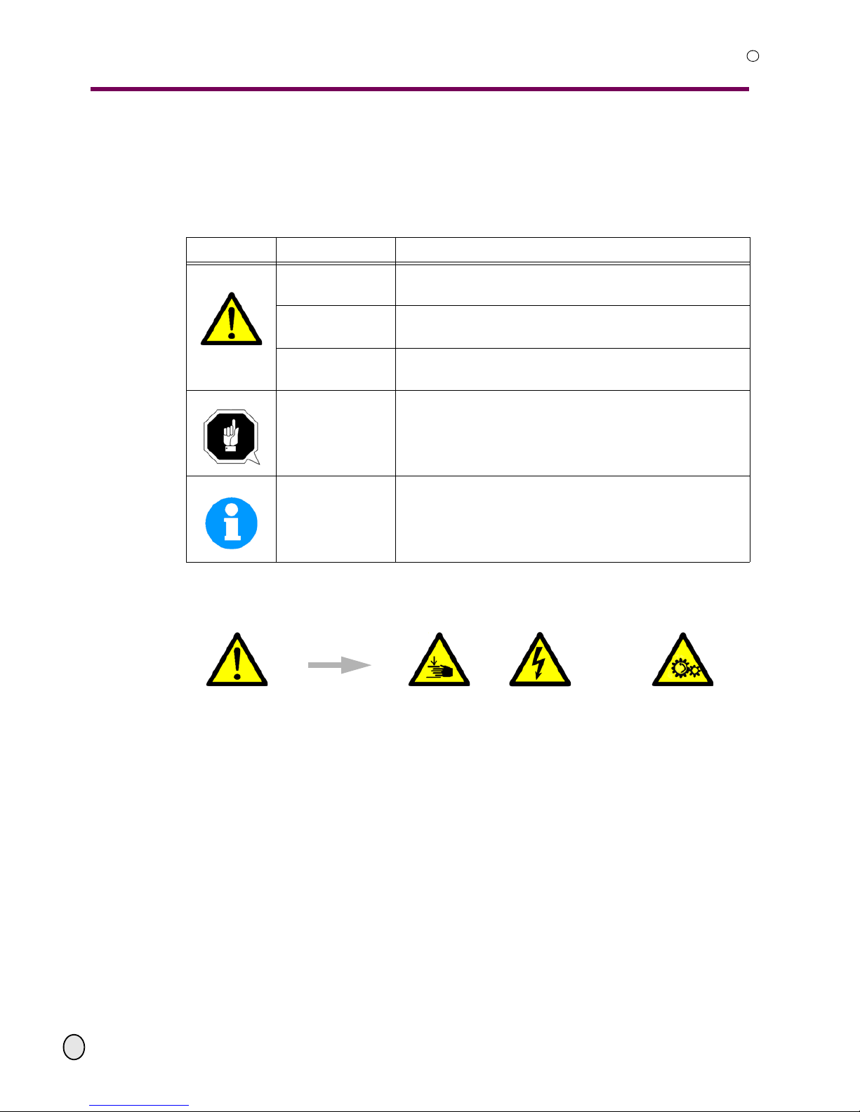
We classify the safety warnings into various levels. The table below gives an overview of the
classification of symbols (ideogram) and warning signs for each specific danger and its (possible) consequences.
ideogram warning alert definition/consequences
DANGER!
Threatening danger that will cause serious injury or death
to people.
WARNING!
Risk: A danger might cause serious injury or death to a
person.
CAUTION!
Danger or unsafe procedure that might cause injury to
people or damage to property.
ATTENTION!
Situation that could cause damage to the machine and to
the product and other types of damages.
No risk of injury to people.
INFORMATION
Application advice and other important or useful information and notes.
No dangerous or harmful consequences for people or
objects.
In case of certain dangers, we replace the ideogram by
or
general danger,
with a warning
of,
injuries of
hands,
hazardous
electrical voltage,
rotating parts.
Page 6

Safety
OPTIMUM
MASCHINEN - GERMANY
© 2008
GB
Page 6 Metal belt saw Opti S 300 VG Version 1.1.0 5 February 2008
R
1.1.2 Further ideograms
1.2 Proper use
Use
WARNING!
Improper use of the metal belt saw
• will endanger personnel,
• will endanger the machine and other property of the operator,
• may affect proper operation of the machine.
The machine is designed and manufactured to be used in environments in which there is no
potential danger of explosion.
The metal belt saw is designed and manufactured to saw cold metal, cast material and plastics
or other material that are not health hazardous and do not generate dust.
The metal belt saw must not be used on wood.
The pieces to be cut must be of a shape that will allow them to be securely attached in the
workholder vice and ensure that the piece does not come loose when it is being sawed.
The metal belt saw must only be installed and operated in a dry and well-ventilated place.
Improper
use!
If the metal belt saw is used in any way other than prescribed above, modified without autorization of Optimum Maschinen GmbH, then the metal belt saw is being used improperly.
We do not take liability for damage caused through improper use.
We would like to stress that any modifications to the construction, or technical or technological
modifications that have not been authorized by Optimum Maschinen GmbH will also render the
guarantee null and void.
It is also part of proper use that
• the maximum values of the metal belt saw are complied with,
• the operating manual is constantly observed,
• inspection and maintenance instructions are observed.
“Technical data“ on page 15
The decisive factor for achieving efficient cutting and the necessary angular tolerance is the correct choice of parameters such as the saw belt, feed, cutting pressure, cutting speed and cooling agent.
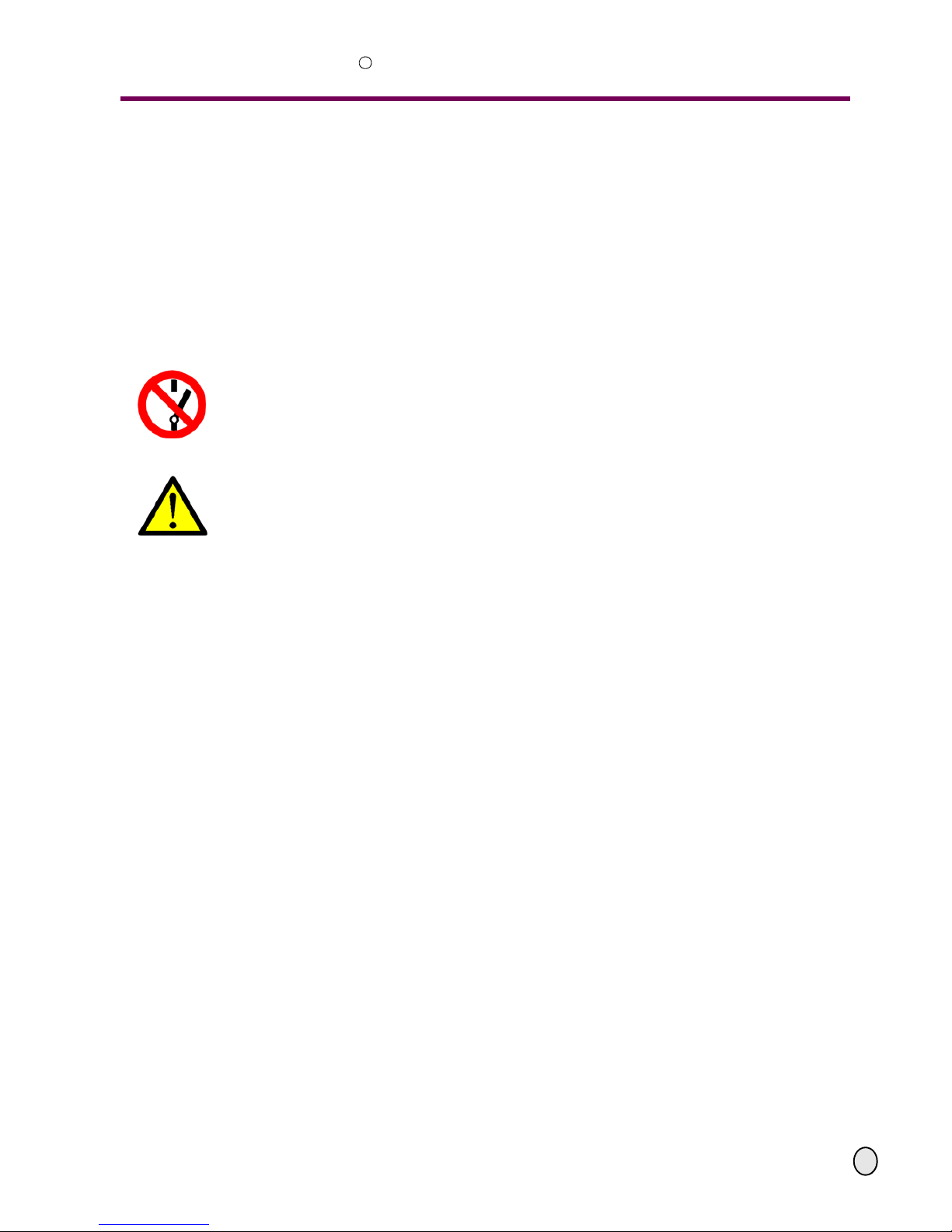
Be aware of slip-
ping!
Activation forbid-
den!
Pull the main plug! Use safety
glasses!
Use ear protec-
tion!
Use protective
gloves!
Use protective
shoes!
Wear a safety suit! Protect the envi-
ronment!
Contact address
Page 7

OPTIMUM
MASCHINEN - GERMANY
Safety
© 2008
GB
Page 75 February 2008 Version 1.1.0 Opti S 300 VG Metal belt saw
R
WARNING!
Very serious injury.
It is forbidden to make any modifications or alternations to the operating values of the
metal belt saw! They could endanger employees and cause damage to the metal belt saw.
1.3 Possible dangers caused by the metal belt saw
The design and construction of the metal belt saw are state of the art.
Nevertheless, there is a residual risk as the metal belt saw operates with
• electrical voltage and currents,
• hydraulic equipment,
• a continuous saw blade.
We have used construction resources an d safety techniques to minimize the health risk to per-
sons resulting from these hazards.
If the metal belt saw is used and maintained by employees who are poorly qualified, then there
might be a risk resulting from incorrect operation and unsuitable maintenance of the metal belt
saw.
INFORMATION
Everyone involved in the assembly, commissioning, operation and maintenance must
• be duly qualified,
• strictly follow this operating manual.
Due to improper use
• there is a risk for the employee,
• the metal belt saw and further property might be endangered,
• the function of the metal belt saw could be affected.
Always disconnect the metal belt saw if cleaning or maintenance work is being carried out.
WARNING!
The metal belt saw may only be used with the safety devices activated. Disconnect the
metal belt saw immediately whenever you detect a failure in the safety device or when
they are not mounted!
All additional installations carried out by the operator must incorporate the safety
devices prescribed.
This is your responsibility being the operator!
“Safety devices“ on page 9
Page 8
Safety
OPTIMUM
MASCHINEN - GERMANY
© 2008
GB
Page 8 Metal belt saw Opti S 300 VG Version 1.1.0 5 February 2008
R
1.4 Qualification of employees
1.4.1 Target group
This manual applies to
• the operators,
• the users,
• the maintenance staff.
Therefore, the warning notes refer to both operation and maintenance of the metal belt saw.
Determine clearly and make a permanent decision in who will be responsible for the different
activities on the machine (operation, ma in te na nc e an d re pair).
Vague and unclear assignment of responsibilities constitute a safety hazard!
Always disconnect the main plug of the metal belt saw. This will prevent the metal belt saw from
being restarted.
1.4.2 Authorized persons
WARNING!
Incorrect use and maintenance of the metal belt saw constitute a danger for the staff,
objects and the environment .
Only authorized persons may operate the metal belt saw!
Persons authorized to operate and maintain should be trained technical staff and instructed by
the ones who are working for the operator and for the manufacturer.
The operator must
Obligations
of the opera-
tor
• train the staff,
• instruct the staff in regular intervals (at least once a year) on
- all safety standards that apply to the machine,
- the operation,
- accredited technical guidelines,
• check the knowledge of the staff,
• document training/instructions,
• require the staff to confirm participation in training/instructions by means of signature,
• check if the staff is aware of safety rules and dangers in the workplace so that they observe
the operating manual.
The user must
Obligations
of the user
• have followed a training on the operation of the metal belt saw,
• know the function and performance,
• before commissioning
- have read and understood the operating manual,
- be familiar with all safety devices and regulations.
Further
require-
ments to the
qualification
For working on the following machine parts, additional requirements are being applied:
• Hydraulic equipment: only specialists with special knowledge/experience in this field.
• Electrical parts or operating agents: shall only be performed by an electrician or under the
guidance and supervision of an electrician.
Page 9
OPTIMUM
MASCHINEN - GERMANY
Safety
© 2008
GB
Page 95 February 2008 Version 1.1.0 Opti S 300 VG Metal belt saw
R
Before starting work on electrical parts or operating agents, following measures are to be
performed in the following order.
- disconnect all poles
- secure against switching on
- check dead circuit
1.5 Safety devices
Operate the metal belt saw only with properly functioning safet y devi ce s.
Stop the metal belt saw immediately if there is a failure in the safety device or if it is not function-
ing for some reason.
It is your responsibility!
If the safety device has been activated or has failed, the metal belt saw must only be operated
again when
• the cause of the failure has been removed,
• you have made sure that there is no existing danger for persons or objects.
WARNING!
If you bypass, remove or override a safety device in any other way, you are endangering
yourself and other persons working on the met al belt saw. The possible consequences
are the following
• injuries due to components or parts of components flying off at high speed,
• contact with rotating and revolting parts,
• fatal electrocution.
The metal belt saw includes the following safety devices:
• a lockable main switch,
• an EMERGENCY-STOP button,
• a saw blade casing with protective cover and position switch,
• a protective cover of the V-belt (cover variator) to switch the speed of the saw blade,
• position switch for the saw blade tension,
• protective covers of the saw blade guide.
Page 10
Safety
OPTIMUM
MASCHINEN - GERMANY
© 2008
GB
Page 10 Metal belt saw Opti S 300 VG Version 1.1.0 5 February 2008
R
1.5.1 Lockable main switch
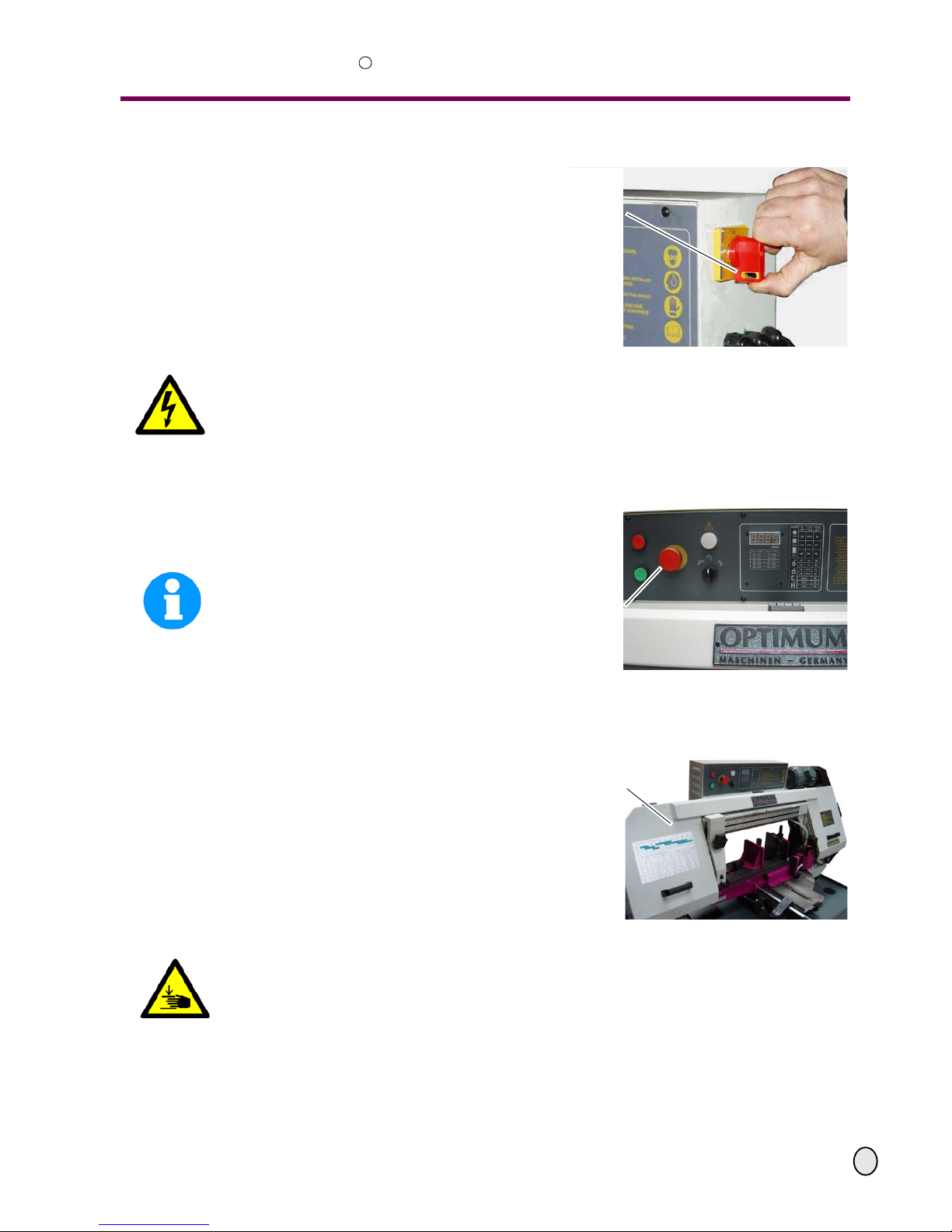
A lockable main switch can be secured by
a padlock in the position " 0 " against
switching on by mistake or unauthorized.
The power supply is interrupted by switching off the main plug.
Except for the positions which are marked
by the ideogram in the margin.
Illustr.1-1: main switch
WARNING!
Dangerous voltage even if the main switch is being switched off. In the pos itions of the
ideogram marked in the margin there might be voltage even if t he main switch is being
switched off.
1.5.2 EMERGENCY-STOP button
The EMERGENCY-STOP button turns the
metal belt saw off.
INFORMATION
After actuation turn the EMERGENCYSTOP button clockwise in order to turn the
metal belt saw on again.
Illustr.1-2: control panel
1.5.3 Saw arch
The arch of the metal belt saw is provided
with a protective cover. The protective
cover covers the belt guide reels and the
revolting saw blade.
The metal belt saw only switches on when
the protective cover is being closed.
Illustr.1-3: saw blade housing with
protective cover
WARNING!
Danger of injury! The teeth of the saw blade are sharp. Take great care when opening the protective cover to change the saw blade.
Close and mount all protective covers before restarting the metal belt saw.
main switch
EMERGENCY-STOP
button
saw arch
Page 11
OPTIMUM
MASCHINEN - GERMANY
Safety
© 2008
GB
Page 115 February 2008 Version 1.1.0 Opti S 300 VG Metal belt saw
R
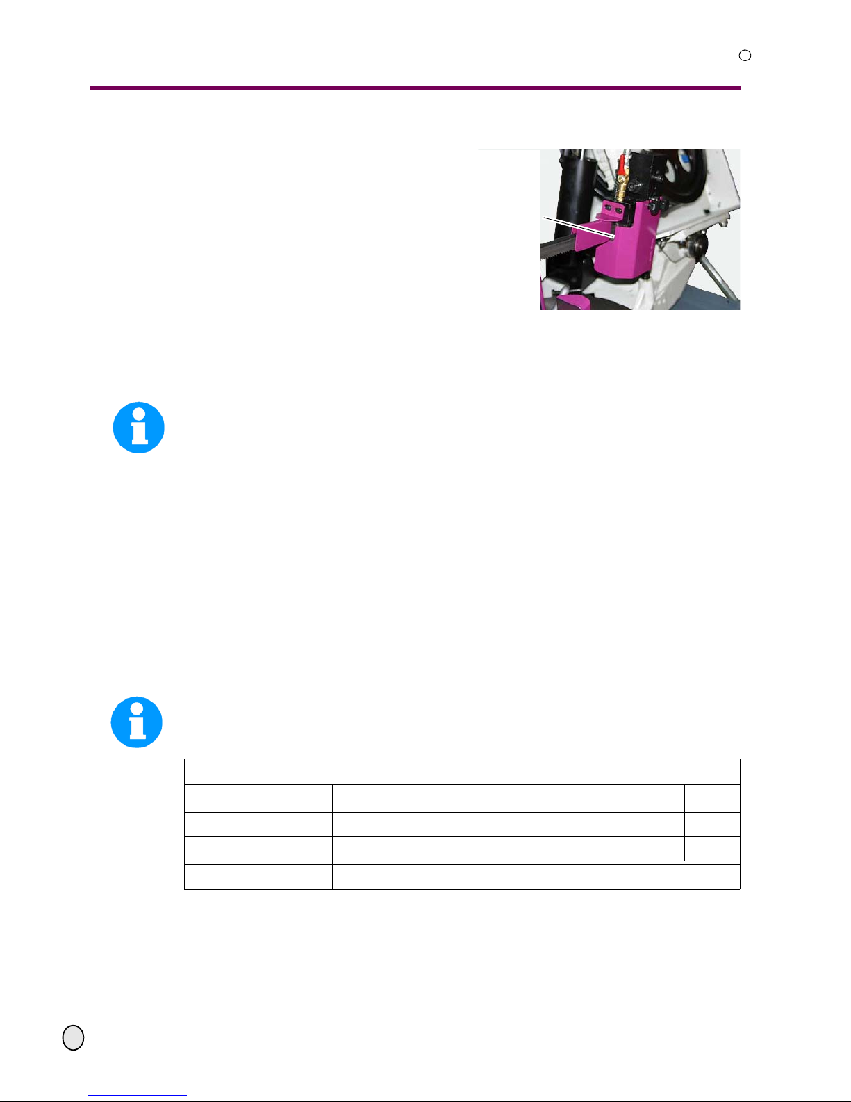
1.5.4 Saw blade guide
Refit the protective covers after each
exchange of the saw blade.
Illustr.1-4: protective covers
saw blade guide
1.5.5 Prohibition, warning and mandatory labels
INFORMATION
All warning labels must be legible. Check them regularly.
1.6 Safety check
Check the metal belt saw at least once per shift. Inform the person responsible immediately of
any defect or change in the operating function.
Check all safety devices
• at the beginning of each shift (with the machine stopped),
• once a week (with the machine in operation),
• after every maintenance and repair work.
Check that the prohibition, warning and information labels as well as the markings on the metal
belt saw
• are legible (clean them, if necessary),
• are complete.
INFORMATION
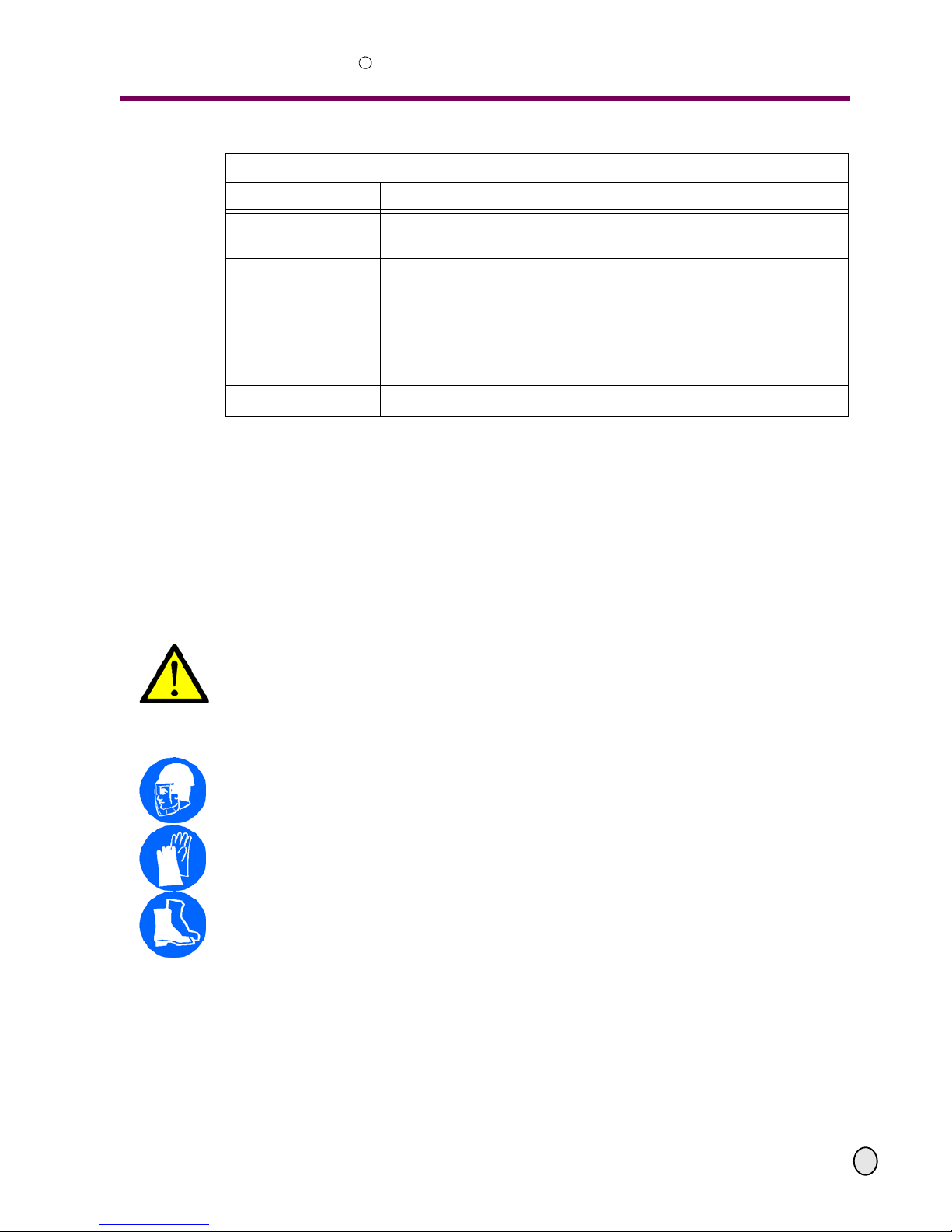
Use the following table to organize the checks.
p
rotective covers on the
right hand saw blade
guide
General checks
equipment check OK
protective covers fitted, firmly bolted and not damaged
labels, markings installed and legible
Date: Checked by (signature):
Page 12
Safety
OPTIMUM
MASCHINEN - GERMANY
© 2008
GB
Page 12 Metal belt saw Opti S 300 VG Version 1.1.0 5 February 2008
R
1.7 Personal protective equipment
For certain work, personal protective equipment is required, such as:
• safety helmet,
• protective glasses or face guard,
• protective gloves,
• safety shoes with steel caps,
• ear protection.
Before starting work, make sure that the prescribed personal protective equipment is available
at the workplace.
CAUTION!
Dirty or eventually contaminated per sonal equipment might cause disease.
Clean your personal protective equipment
• after each use,
• regularly once a week.
Personal protective equipment for special work
Protect your face and your eyes: Wear a safety helmet with a face guard for every work, especially for the kind of work where your face and eyes are exposed to hazards.
Use protective gloves when lifting or handling pieces with sharp edges.
Wear safety shoes when fitting, dismanteling or transporting heavy components.
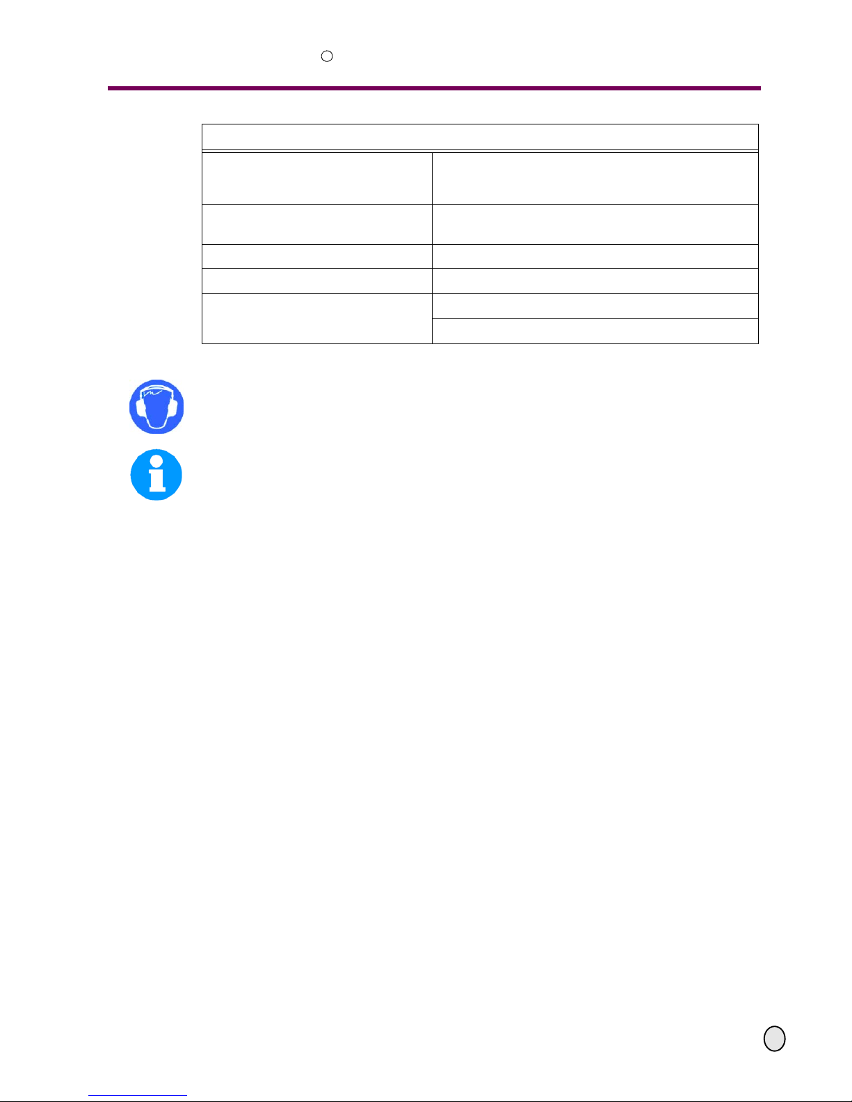
Functional testing
equipment check OK
EMERGENCY-STOP
button
The metal belt saw must disconnect when the EMERGENCY-STOP button is activated.
position switch
protective cover
saw arch
The metal belt saw may only switch on when the protective
cover is being closed.
position switch
tension of the saw
blade
The metal belt saw may only switch on when the saw blade
is well stretched.
Date: Checked by (signature):
Page 13

OPTIMUM
MASCHINEN - GERMANY
Safety
© 2008
GB
Page 135 February 2008 Version 1.1.0 Opti S 300 VG Metal belt saw
R
1.8 Safety during operation
In the description of work with and on the metal belt saw we highlight the dangers specific to that
work.
WARNING!
Before activating the metal belt saw, double chec k that this will
• not endanger other people,
• not cause damage to equipment.
Avoid unsafe working practice:
• Make sure that your work does not endanger anyone.
• The instructions of this manual must be observed strictly during assembly, operation, maintenance and repair.
• Do not work on the metal belt saw if your concentration is reduced, for example, because
you are taking medication.
• Observe the regulations for the prevention of accidents issued by your association for the
prevention of accidents and safety in the workplace or other inspection authorities.
• Stay at the metal belt saw until all rotating parts have come to a halt.
• Use the prescribed personal protective equipment. Make sure you wear a well-fitting work
suit and a hairnet, if necessary.
• Do not wear gloves when sawing parts, use the spray gun to remove sawdust during the
sawing proceedure.
• Inform the inspector of any danger or failure.
1.9 Safety during maintenance
Report and
document
any changes
Inform the operators on time of any maintenance and repair work.
Report all safety relevant changes or performance details of the metal belt saw. Document all
changes, have the operation manual changed accordingly and train the machine operators.
1.9.1 Switching off and securing the metal belt saw
Unplug the metal belt saw from electrical supply and secure the metal belt saw against restarting by a padlock on the main switch.
Place a warning sign on the machine.
1.9.2 Use of lifting equipment
WARNING!
Use of unstable lifting and load-suspension gear that might break under load can cause
very serious injuries or even death.
Check the lifting and load-suspension gear on
• sufficient load capacity,
• perfect condition.
Observe the regulations for the prevention of accidents issued by your association for
the prevention of occupational accidents and safety in the workplace or other inspection
authorities.
Fasten the loads properly.
Do not walk under lifted loads!
Page 14

Safety
OPTIMUM
MASCHINEN - GERMANY
© 2008
GB
Page 14 Metal belt saw Opti S 300 VG Version 1.1.0 5 February 2008
R
1.9.3 Mechanical maintenance work
Remove all protection and safety devices before starting maintenance work and re-install them
once the work has been completed, such as:
• covers,
• safety indications and warning signs,
• earth (ground) cables.
If you remove protection or safety devices, refit them immediately after completing the work.
Check if they are working properly!
1.10 Accident report
Inform your superiors and Optimum Maschinen GmbH immediately in case of accidents, possible sources of danger and any action which almost lead to and accident „near misses“.
„Near misses“ may have many possible causes.
The sooner they are notified, the faster these causes can be eliminated.
INFORMATION
In the description of execution of work with and on the metal belt saw we highlight the dangers
specific to that kind of work.
1.11 Electric
Have the machine and/or the electrical equipment checked regularly, at least every six months.
Eliminate immediately all defects such as loose connections, defective wires, etc.
A second person must be present during work on live components, to disconnect the power in
case of an emergency.
Disconnect the metal belt saw immediately if there is a malfunction in the power supply!
1.12 Hydraulic equipment
The system has got a pressure of up to 280 bars.
WARNING!
Serious injury due to hydraulic fluid which escapes with high pressure!
Possible loss of the eyesight!
Make sure that the hydraulic equipment with valves is without pressure before you open a component or a line. Wear protective glasses when working on the hydraulic system.
When you are having hydraulic fluids in your eyes rinse them immediately with lots of water.
Consult a doctor immediately.
Page 15

OPTIMUM
MASCHINEN - GERMANY
Technical data
© 2008
GB
Page 155 February 2008 Version 1.1.0 Opti S 300 VG Metal belt saw
R
2 Technical data
2.1 Data plate
Illustr.2-1: data plate
The following information give the dimensions and weight and is the manufacturer’s authorized
machine data.
2.2 Power connection
sawing engine 400V ~50Hz; 1,5 KW
cooling pump 400V ~50Hz; 0,1 KW
total connection rate 3x400V ~50Hz (60Hz); 1,7 KW
2.3 General
raising the saw arm manually
feed hydraulic by means of a lowering cylinder
speed of saw blade infinitely variable
dimensions of saw blade 27 x 0,9 x 3352
Height to machine vice 750 mm
2.4 Weight
weight metal belt saw [kg] 410
floor loading [ KN / m
2
]7
2.5 Speed of saw blade
for a connection of ~ 50Hz - [m/min] infinitely 25 ~ 100
for a connection of ~ 60Hz - [m/min] infinitely 30 ~ 120
2.6 Environmental conditions
temperature 5°-35 °C
humidity 25 - 80 %
Page 16
Technical data
OPTIMUM
MASCHINEN - GERMANY
© 2008
GB
Page 16 Metal belt saw Opti S 300 VG Version 1.1.0 5 February 2008
R
2.8 Emissions
The development of noise (sound pressure level) of the metal belt saw at the workplace could
exceed the level of 80 dB(A).
INFORMATION
We recommend the use of sound insulation and ear protection. Please note, the duration of
noise pollution, the type and characteristics of the working area, such as other machines which
are operated simultaneously, influence the development of noise at the workplace.
2.7 Operating agents
hydraulics hydraulic oil, viscosity from 32 to 46 according to DIN
51519,
quality HLP
gearbox high- performance gear-oil
Mobilgear 636, viscosity 680 mm2/s
spindle of the machine vice commercial lubricating grease
bushing- type bearing commercial lubricating grease
cooling appliance
commercial cooling agent
maximum filling quantity 30 litres
Page 17
OPTIMUM
MASCHINEN - GERMANY
Technical data
© 2008
GB
Page 175 February 2008 Version 1.1.0 Opti S 300 VG Metal belt saw
R
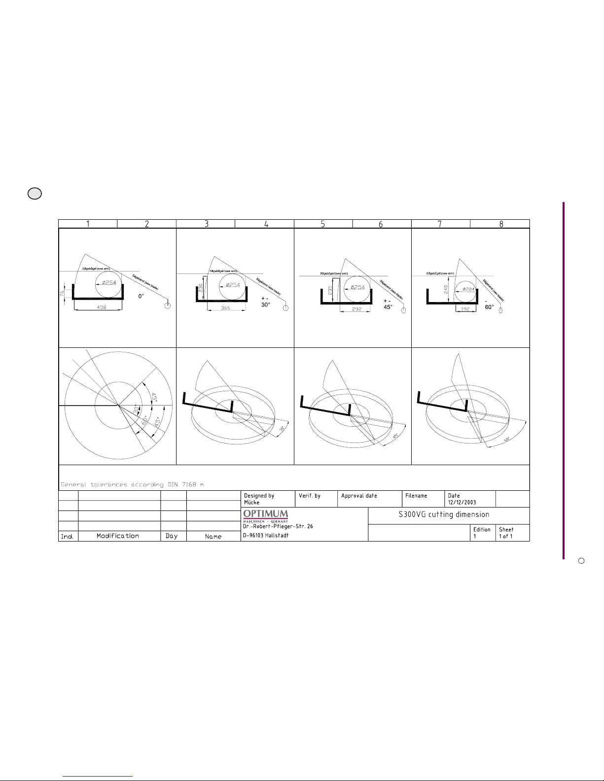
2.9 Cutting area
Page 18

Technical data
OPTIMUM
MASCHINEN - GERMANY
© 2008
GB
Page 18 Metal belt saw Opti S 300 VG Version 1.1.0 5 February 2008
R
2.10 Dimensions
Page 19
OPTIMUM
MASCHINEN - GERMANY
Assembly
© 2008
GB
Page 195 February 2008 Version 1.1.0 Opti S 300 VG Metal belt saw
R
3 Assembly
INFORMATION
The metal belt saw is pre-assembled.
3.1 Delivery volume
When the metal belt saw is delivered, please check immediately that the machine has not been
damaged during transportation and that all components are included. Also check that the set
screws are well tightened.
• 1x metal belt saw
• 1x saw blade 4 to 6 teeth per inch
• 1x material stop
• 1x deflector for coolant and chips machine vice
• 2x additional mountable coolant drain pan
• 1x set of set screws
• 1x set of colours
• 1x operating manual
3.2 Optional machine accessories
3.3 Storage
ATTENTION!
Improper storage may cause important parts to be damaged or destroyed.
Store packaged or unpacked parts only under the following external conditions
“Environmental conditions“ on page 15
Consult Optimum Maschinen GmbH if the metal belt saw and accessories have to be stored for
a period of over three months or under different ambience conditions to those given here.
3.4 Transport
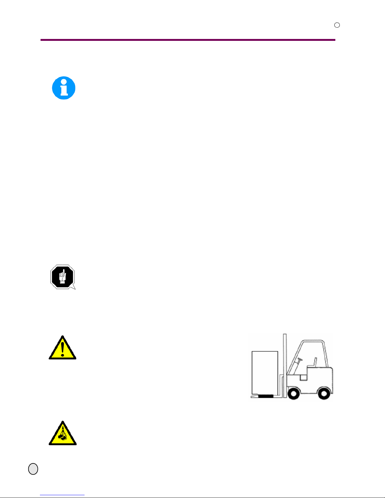
WARNING!
Machine parts falling off forklift trucks or other trans-
port vehicles could cause very serious or even fatal
injuries. Follow the instructions and information on the
transport case:
• centre of gravity
• suspension points
• weights
• means of transport to be used
• prescribed shipping position
Illustr.3-1: shipping position
WARNING!
Use of unstable lifting and load suspension gear that might break under load can cause
very serious injuries or even death.
Check that the lifting and load suspension gear has sufficient load capacitiy and that it is
in perfect condition. Observe the regulations for the preve ntion of accidents. Fasten the
loads properly. Do not walk under lifted loads!
designation part number
HSS bi-metal M42 saw blade (10 to 14 teeth per inch) 335 7532
Page 20
Assembly
OPTIMUM
MASCHINEN - GERMANY
© 2008
GB
Page 20 Metal belt saw Opti S 300 VG Version 1.1.0 5 February 2008
R
3.4.1 Load end
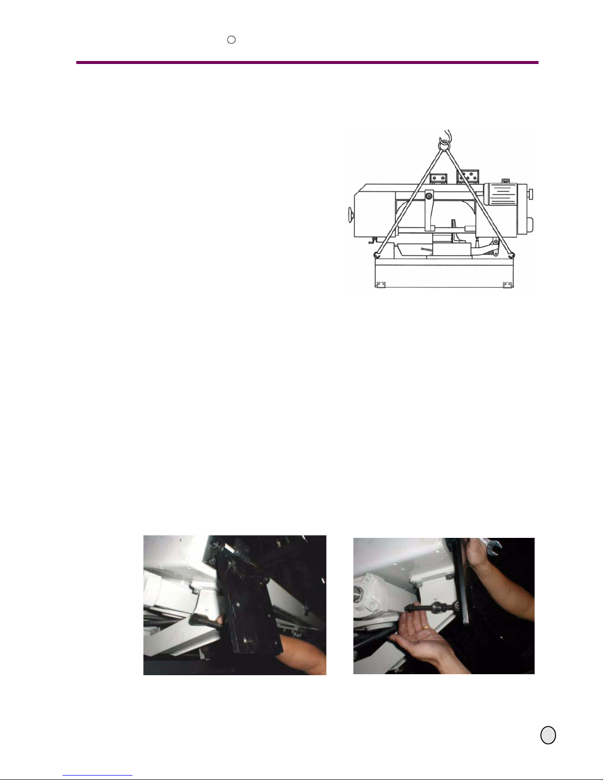
Fasten the load end material on the
assigned load end positions on the machine
substructure.
Tighten all set screws. Assemble the secur-
ing device of the saw arch when the metal
belt saw is again being transported over a
long distance.
Use an adequate conveyor equipment; for
instance a crane.
Make sure that you have an equal load end
position and that the metal belt saw cannot
overturn when lifted.
Make sure that the load end does not dam-
age any accessories or causes damages to
the paintwork.
Illustr.3-2: Load end
The net weight of the machine is 410 kg.
3.5 Installation and assembly
3.5.1 Requirements to the installation sight
Organize the work area around the metal belt saw in accordance with the local safety regulations.
Operation, maintenance and repair in the work area must not be hindered.
3.5.2 Assembly
Check the foundation of the metal belt saw with a spirit level on horizontal alignment. Equal-
ize unevenesses by metal plates or other adequate material.
Fasten the machine substructure to the machine foun dation when th e met al belt saw is bein g
connected to the power supply stationary.
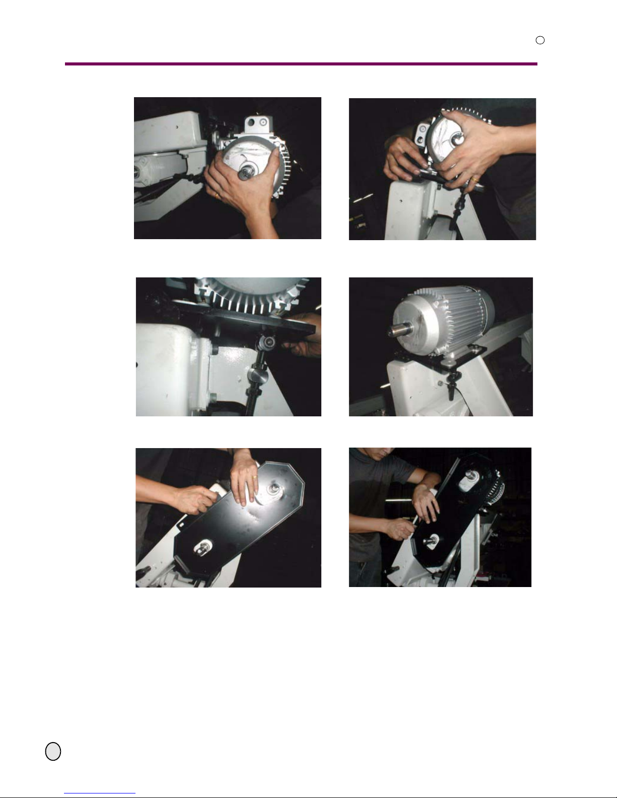
3.5.3 Installation of the motor
Illustr. 3-3: Fix the motor plate. Illustr. 3-4: Fix the clamp.
Page 21
OPTIMUM
MASCHINEN - GERMANY
Assembly
© 2008
GB
Page 215 February 2008 Version 1.1.0 Opti S 300 VG Metal belt saw
R
Illustr. 3-5: Place the motor. Illustr. 3-6: Mount the fixing screws of the motor
(4 pcs.).
Illustr. 3-7: Tighten the motor screws (4 pcs.). Illustr. 3-8: Fix the motor screws (4 pcs.).
Illustr. 3-9: Mount the rear protecting cover . Illustr. 3-10: Fit the screws (2 pcs).
Page 22
Assembly
OPTIMUM
MASCHINEN - GERMANY
© 2008
GB
Page 22 Metal belt saw Opti S 300 VG Version 1.1.0 5 February 2008
R
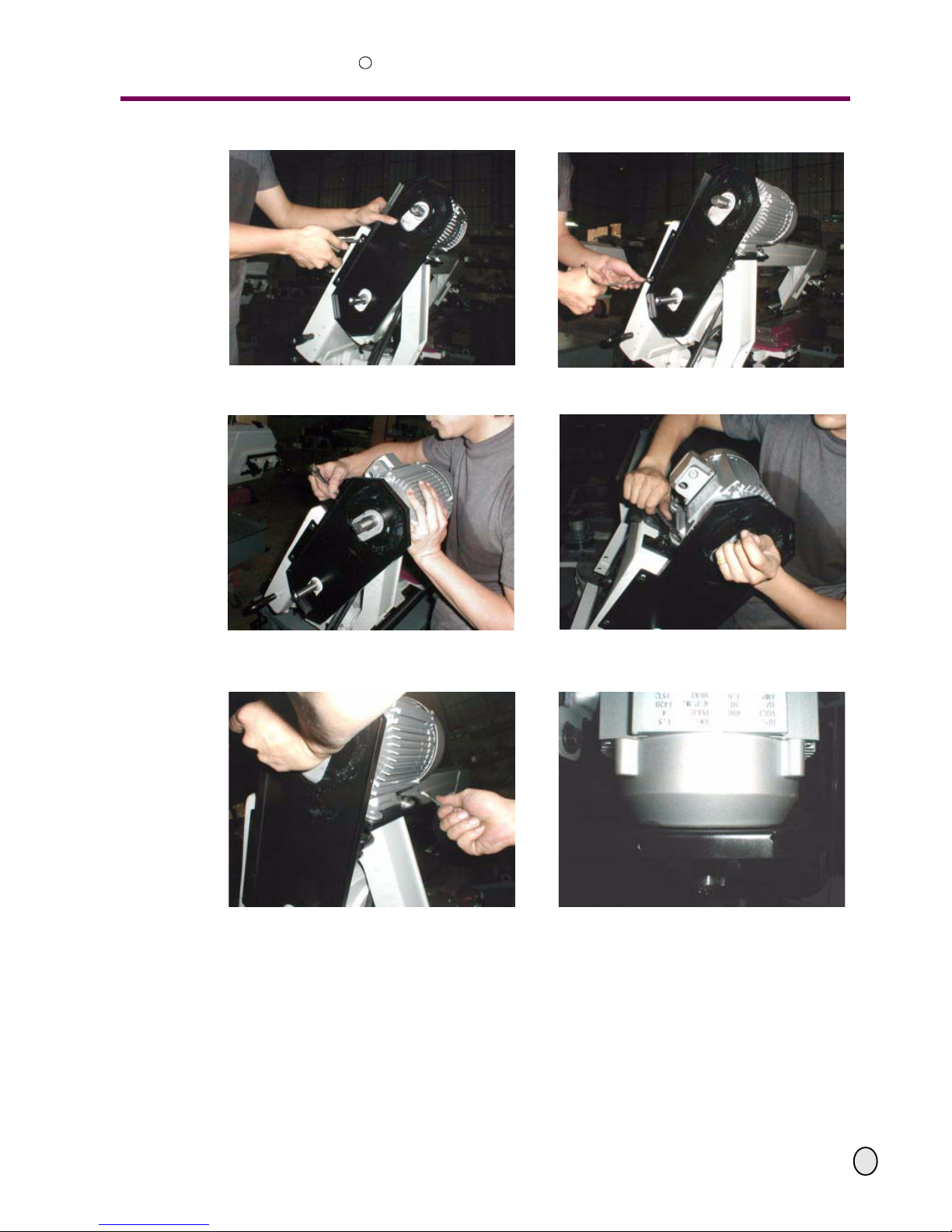
Illustr. 3-11: Tighten the screws (2 pcs). Illustr. 3-12:
Illustr. 3-13: Adjust the distance between the motor
and the rear protective cover.
Illustr. 3-14:
Illustr. 3-15: Tighten the fixing screws after having
adjusted the distance.
Illustr. 3-16: Distance
Page 23
OPTIMUM
MASCHINEN - GERMANY
Assembly
© 2008
GB
Page 235 February 2008 Version 1.1.0 Opti S 300 VG Metal belt saw
R
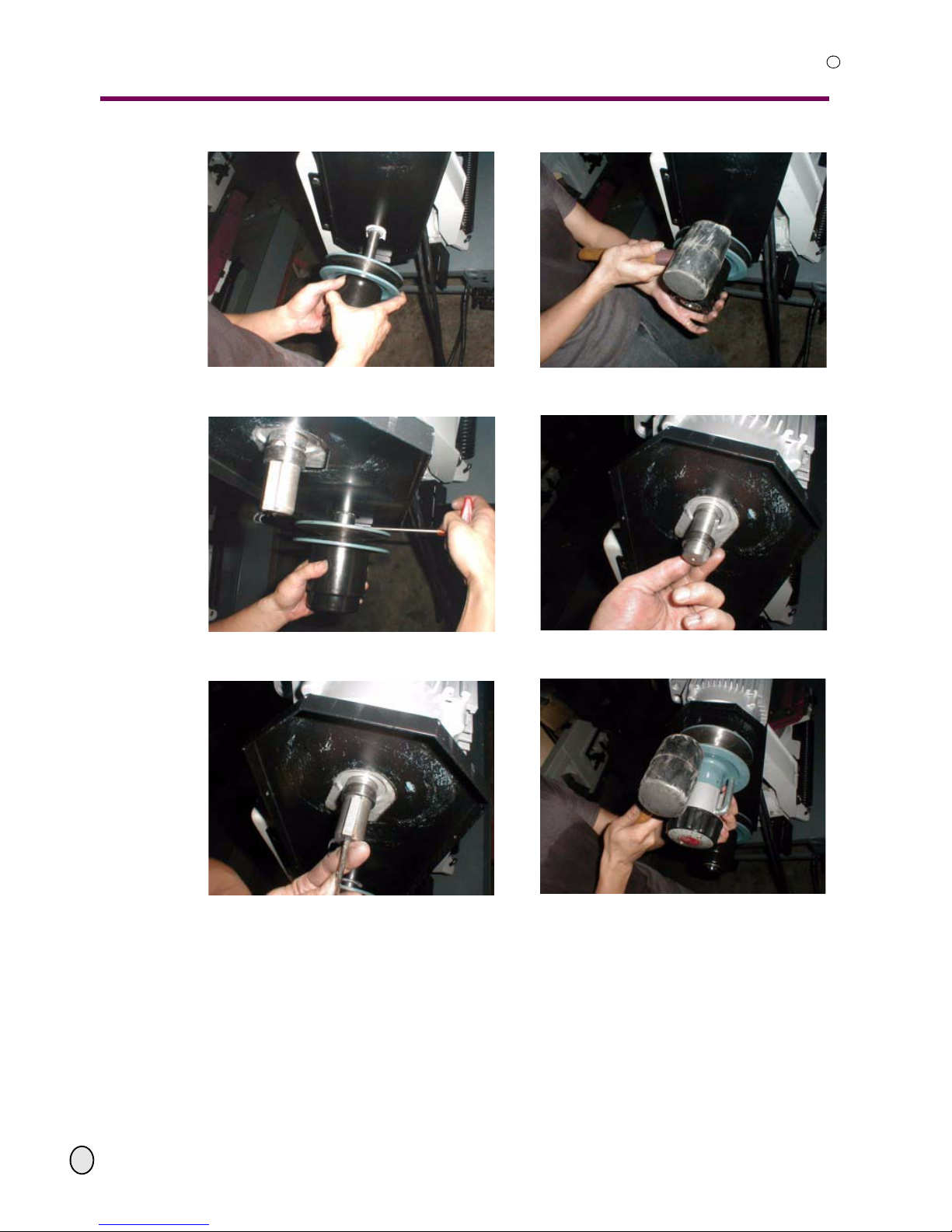
Illustr. 3-17: Mount the pulley. Illustr. 3-18:
Illustr. 3-19: Mount and tighten the safety screw. Illustr. 3-20: Mount the ring of the motor shaft.
Illustr. 3-21: Fit the feather key. Illustr. 3-22: Mount the variator.
Page 24
Assembly
OPTIMUM
MASCHINEN - GERMANY
© 2008
GB
Page 24 Metal belt saw Opti S 300 VG Version 1.1.0 5 February 2008
R
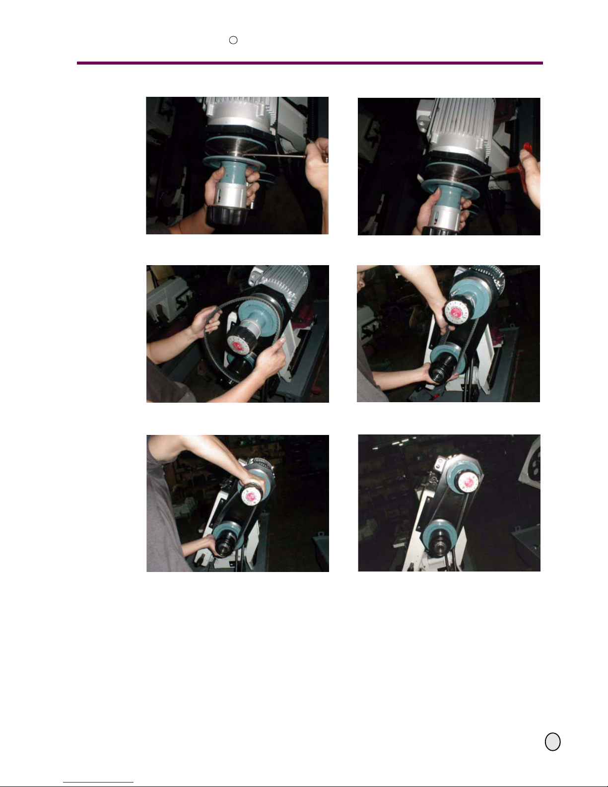
Illustr. 3-23: Tighten the screw Illustr. 3-24:
Illustr. 3-25: Place the V-belt. Illustr. 3-26:
Illustr. 3-27: Illustr. 3-28: V-belt installed.
Page 25
OPTIMUM
MASCHINEN - GERMANY
Assembly
© 2008
GB
Page 255 February 2008 Version 1.1.0 Opti S 300 VG Metal belt saw
R
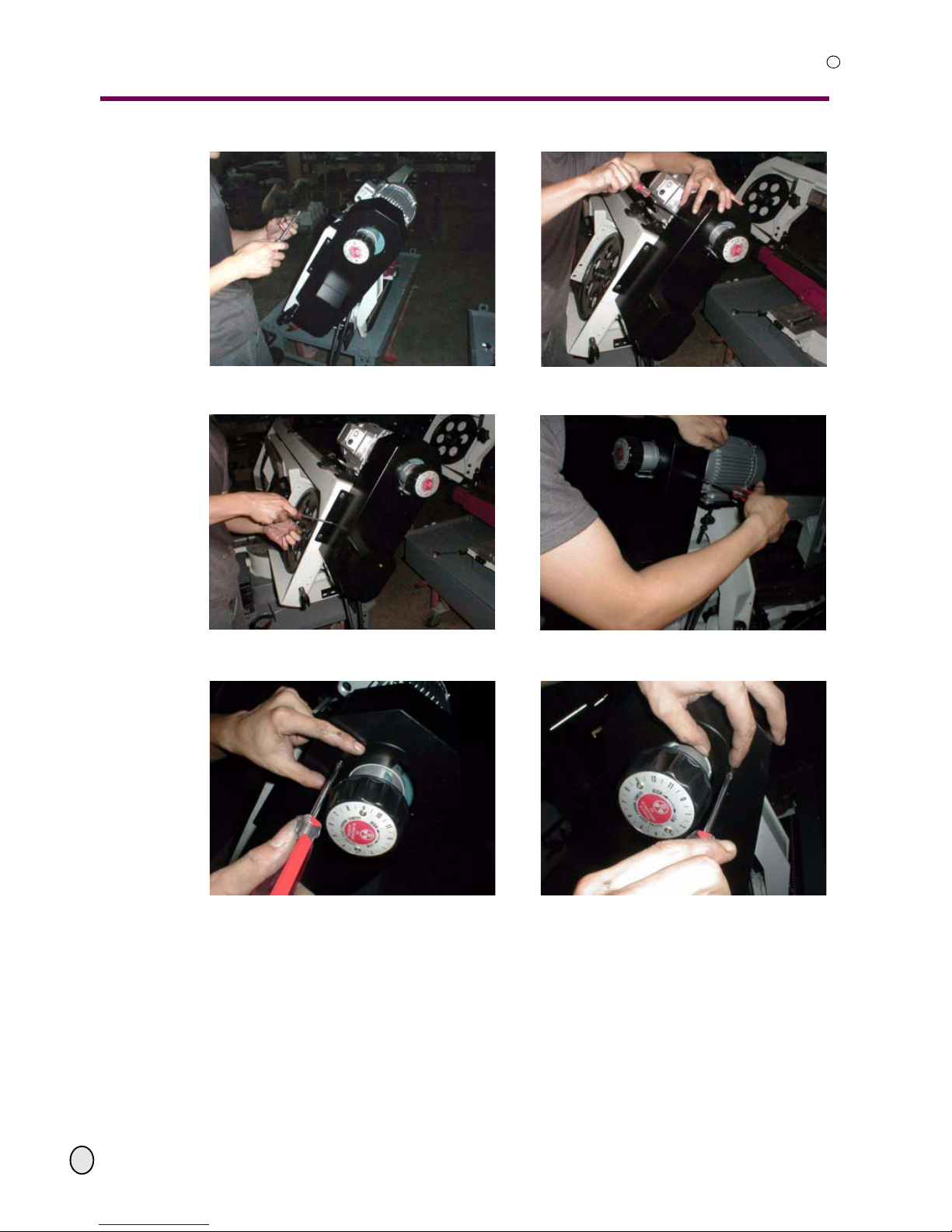
Illustr. 3-29: Install the protective cover in the front. Illustr. 3-30:
Illustr. 3-31: Illustr. 3-32:
Illustr. 3-33: Illustr. 3-34:
Page 26
Assembly
OPTIMUM
MASCHINEN - GERMANY
© 2008
GB
Page 26 Metal belt saw Opti S 300 VG Version 1.1.0 5 February 2008
R
3.5.4 Installation plan
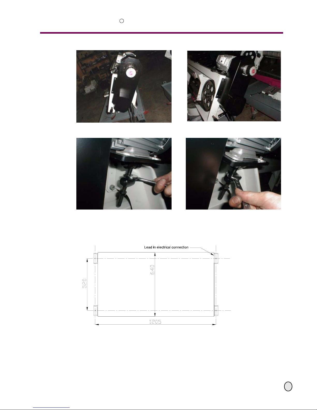
Illustr. 3-35: Protective cover installed. Illustr. 3-36: Protective cover installed.
Illustr. 3-37: Turn right to increase the speed rate. Illustr. 3-38: Turn left to decrease the speed rate.
Page 27
OPTIMUM
MASCHINEN - GERMANY
Assembly
© 2008
GB
Page 275 February 2008 Version 1.1.0 Opti S 300 VG Metal belt saw
R
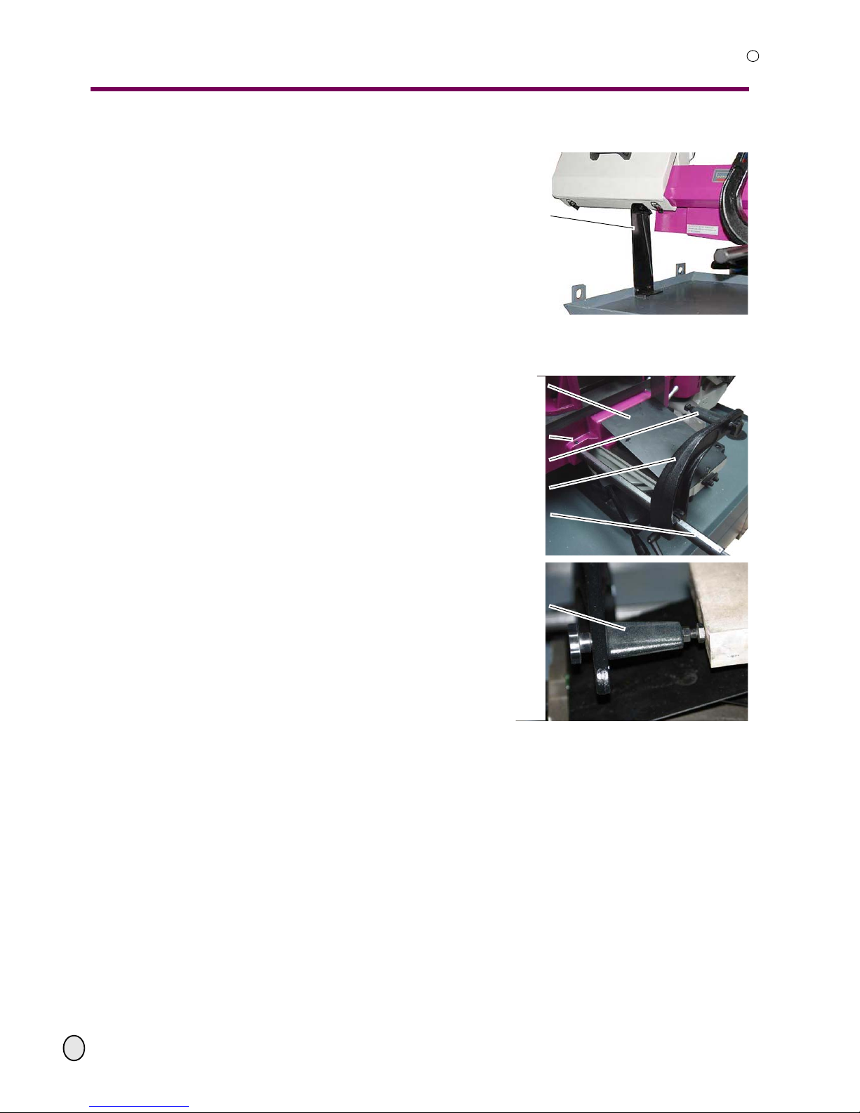
Securing device
Disassemble the securing device.
Illustr.3-39: securing device
Depth stop
Insert the motion rod into the location
hole.
Mount the depth stop to the impact
arch.
Adjust the position of the motion rod in
the location hole with the scale to the
saw blade by means of the clearance of
the depth stop.
Clamp the motion rod with the two
clamping screws (front and rear).
Illustr.3-40: depth stop
Skirtboard for chips guideway machine vice
Put the skirtboard for chips on the guideway of the machine vice, see Illustr.3-40: “depth
stop“ on page 27.
securing device
skirtboard for chips
front clamping screw
depth stop
depth stop arch
motion rod with scale
depth stop
Page 28
Assembly
OPTIMUM
MASCHINEN - GERMANY
© 2008
GB
Page 28 Metal belt saw Opti S 300 VG Version 1.1.0 5 February 2008
R
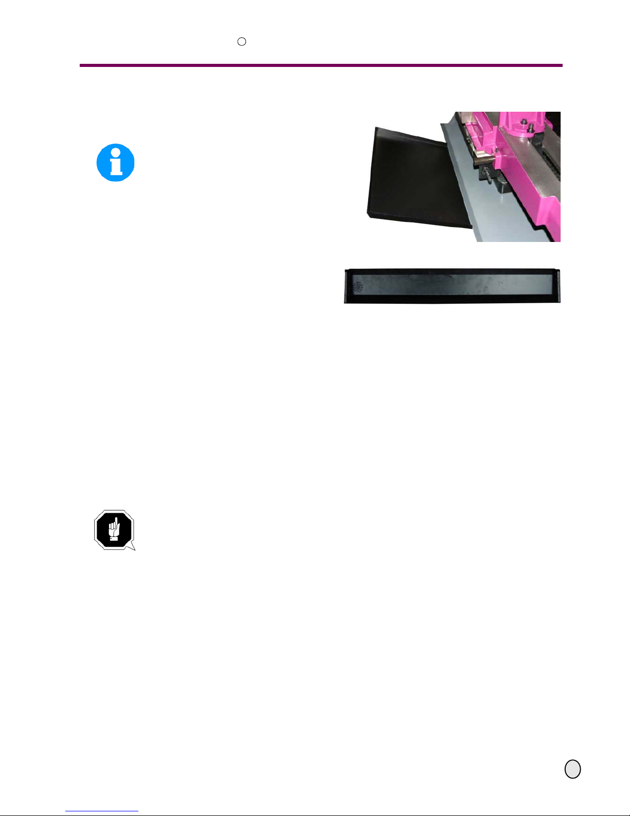
Drain pan for coolant
Mount a larger drain pan, if necessary.
INFORMATION
There is no tapped hole prepared in the
machine substructure. Fix the drain pan to
the position which corresponds best to the
use of the metal belt saw itself and the
local conditions.
Illustr.3-41: rear drain pan
If necessary, put the drain pan to the skirtboard in order to collect the coolant which
discharges over the workpiece.
Illustr.3-42: drain pan
3.5.5 Cleaning and lubricating
Remove the anti-corrosive agent applied to metal belt saw for transport and storage pur-
poses. We recommend the use of kerosene.
Do not use any solvents, thinner or other cleaning ag ents which could corrode the varnish on
the metal belt saw. Follow the specifications and indications of the manufacturer of the cleaning agent.
Lubricate the bright machine parts with acid-free lubricating oil.
Grease the metal belt saw according to the lubrication chart.
3.5.6 Checks
Perform the following checks.
ATTENTION!
Danger of cutting, perform the works described hereunder with care. Use the prescribed
protective equipment.
Direction of the sawteeth
Control the direction of the sawteeth. The sawteeth must point to the drive engine.
Running direction of the saw blade
The running direction of the saw blade is counter-clockwise.
Page 29
OPTIMUM
MASCHINEN - GERMANY
Assembly
© 2008
GB
Page 295 February 2008 Version 1.1.0 Opti S 300 VG Metal belt saw
R
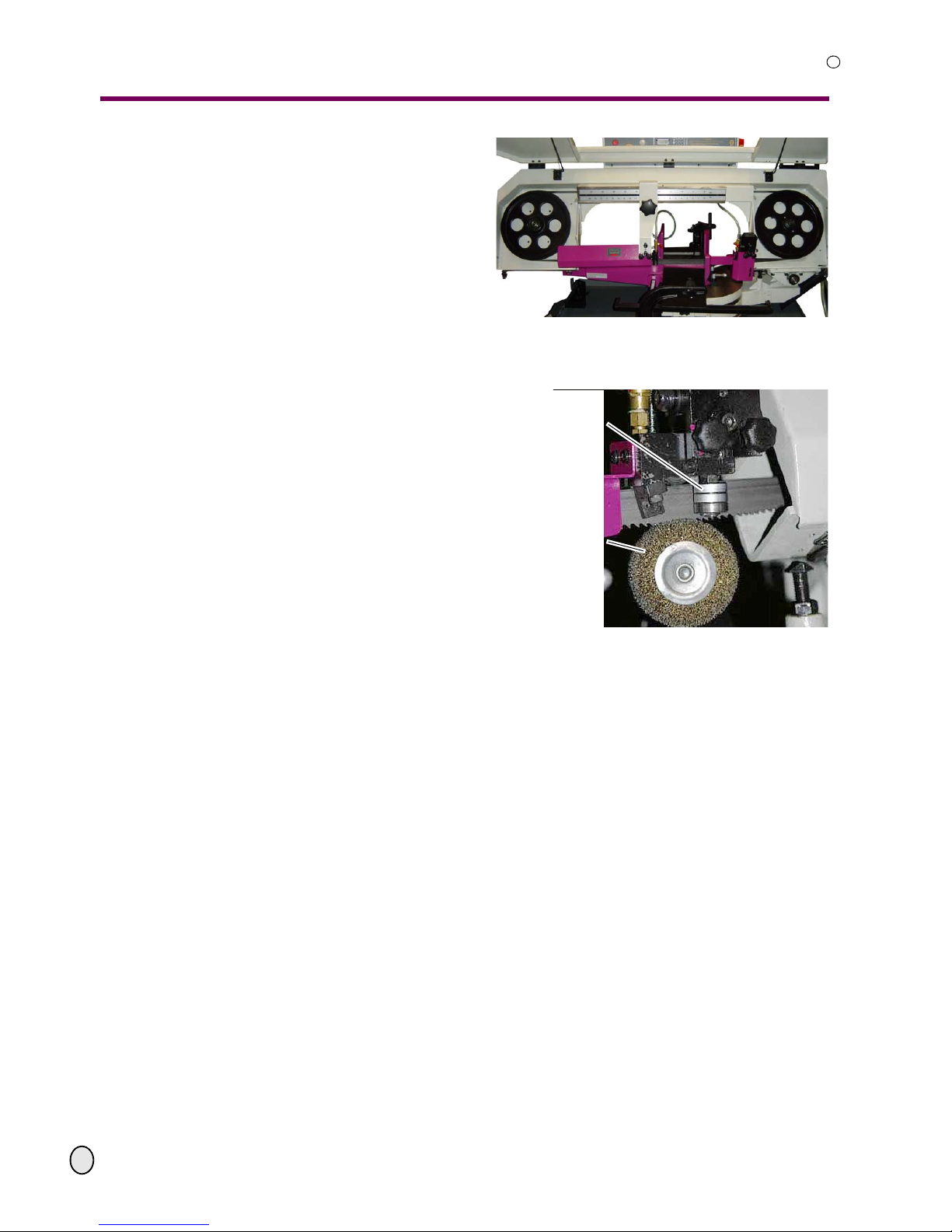
Controlling the saw blade pulleys
Control if the saw blade is mounted cor-
rectly onto the saw blade pulleys. The
saw blade must be in contact to the
recess of each pulley.
Illustr.3-43: saw blade pulleys
Lateral pilot bearings of the saw blade
Control if the saw blade is positioned
between the lateral pilot bearings.
Illustr.3-44: saw blade guidance on the
right hand side
Tension of the saw blade
Control the tension of the saw blade.
“Adjusting the tension of the saw blade“ on page 47
Oil level of the gear
Control the oil level. “gear“ on page 46
Coolant
Fill in coolant. “liquid cooling system“ on page 49
pilot bearing on the
right in front
saw blade brush
Page 30

Assembly
OPTIMUM
MASCHINEN - GERMANY
© 2008
GB
Page 30 Metal belt saw Opti S 300 VG Version 1.1.0 5 February 2008
R
3.6 Power connection
ATTENTION!
For connection, install a lockable switch or use a CEE 16 A combined plug.
Check the rotation field. If the rotation direction should be wrong, then exchange two of the three
phases. Check the pre-mounted electrical fuse protection. We recommend a fuse protection of
10 ampers per phase. Use slow to blow fuses. Use a connection cable with a cross-section of at
least 1.5 mm
2
.
ATTENTION!
Please pay attention that all three phases ( L1, L2, L3) are conne cted correctly.
Most engine failure result from incorrect connection for instance the neutral conductor
(N) is being connected to a phase
This might lead to the following results :
• the engine does get quickly very hot.
• the engine noise increases, i.e. becomes louder.
• the enine has no power.
When the phases are connected wrongly, the guarantee is being null and void.
3.7 First use
WARNING!
Staff and equipment may be endangered if the metal belt saw is first used by untrained
personnel. We do not take any liability for damages caused by incorrect commissioning.
Page 31
OPTIMUM
MASCHINEN - GERMANY
Operation
© 2008
GB
Page 315 February 2008 Version 1.1.0 Opti S 300 VG Metal belt saw
R
4 Operation
4.1 Safety
Use the metal belt saw only under the following conditions:
• The metal belt saw is in proper working condition.
• The metal belt saw is used as prescribed.
• The operation manual is followed.
• All safety devices are installed and activated.
All malfunctions should be eliminat ed imm ed ia te ly. Stop the machine immediately in the event of
any malfunction in operation and make sure it cannot be started up accidentally or without
authorisation.
Notify the person responsible immediately of any modification.
“Safety during operation“ on page 13
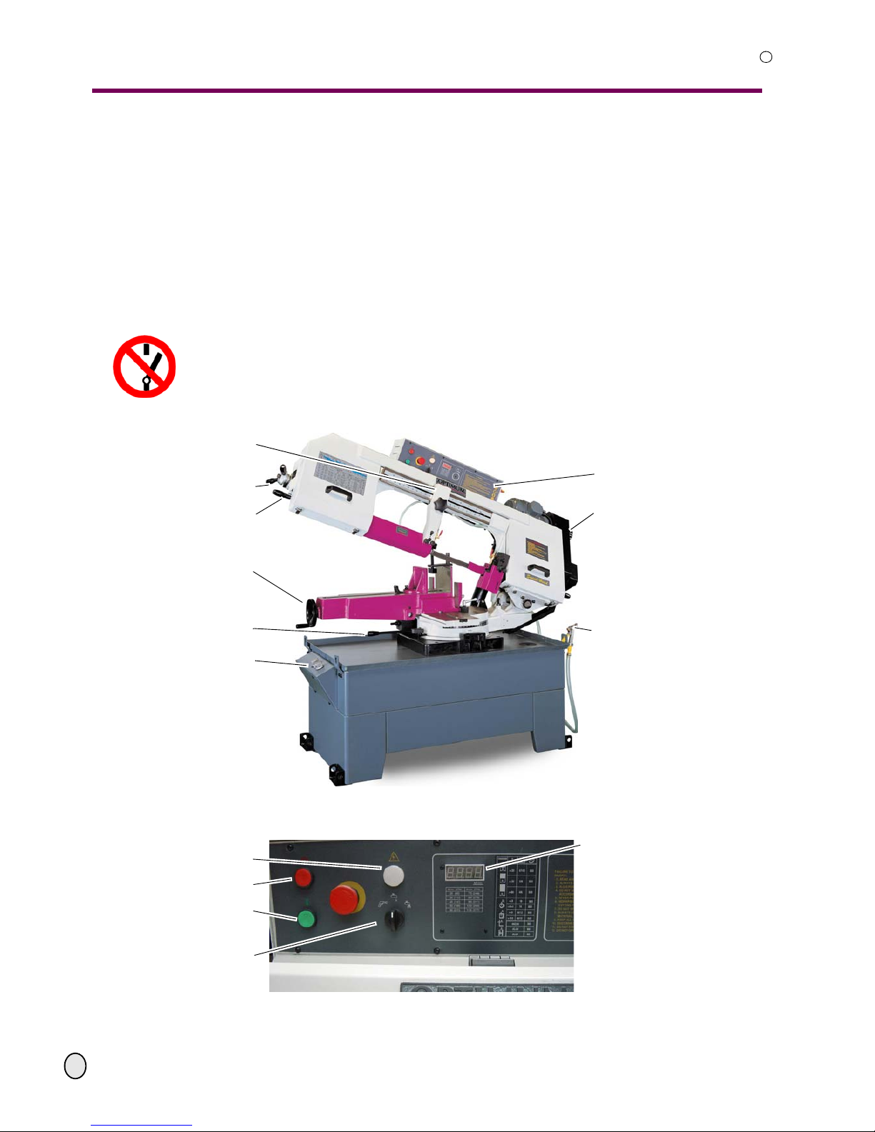
4.2 Control and indicating elements
Abb.4-1: Opti S 300 VG
4.2.1 Control panel
Abb.4-2: Control panel on the metal belt saw
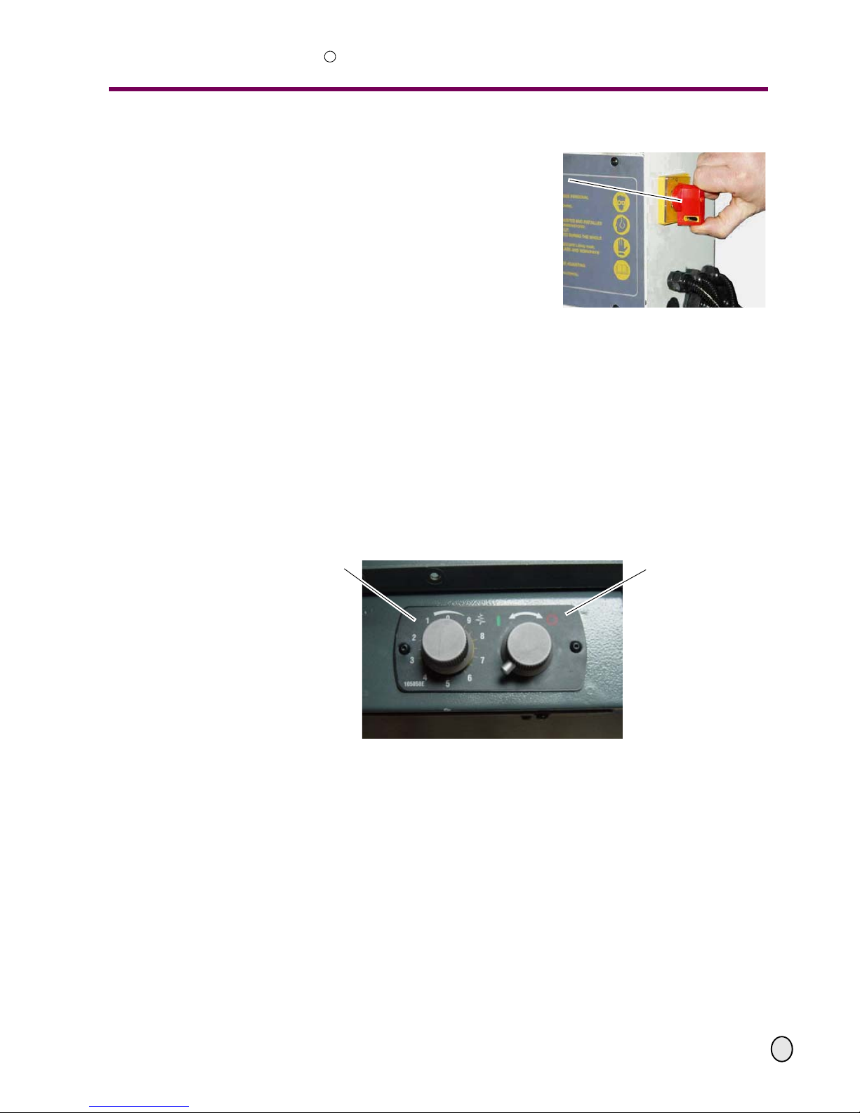
control panel
saw blade speed adjusting
spray gun
adjustable guidance of the saw blade
and the coolant tube with scale
adjusting tension of saw blade
handle
handwheel machine vice
clamping lever saw arch
control panel hydraulic lowering of
the saw arch
operation control lamp
Metal belt saw "ON"
Metal belt saw "OFF"
Cooling pump "ON/ OFF"
activation spray gun
digital display of cutting speed
Page 32
Operation
OPTIMUM
MASCHINEN - GERMANY
© 2008
GB
Page 32 Metal belt saw Opti S 300 VG Version 1.1.0 5 February 2008
R
Operation control lamp
The operation control lamp is on when the
main switch is on.
EMERGENCY-STOP button
The EMERGENCY-STOP button switches
the metal belt saw off.
Button "ON"
The button "ON" switches the running of
the saw blade on.
Button "OFF"
The button "OFF" switches the running of the saw blade off.
Coolant button
The coolant button switches the coolant pump ON/OFF and/or additionally activates the use of
the spray gun.
Digital display
The digital display shows the speed of the saw blade in meters per minute.
4.2.2 Control panel hydraulics
Abb.4-3: Control panel on the chip pan
4.2.3 Control elements
Digital display of the speed of the saw blade
• “Control panel on the metal belt saw“ on pag e 31
Operation lamp
• “Control panel on the metal belt saw“ on pag e 31
main switch
adjusting the down speed
feed check valve
Opening / Closing of the
lowering valve
Page 33
OPTIMUM
MASCHINEN - GERMANY
Operation
© 2008
GB
Page 335 February 2008 Version 1.1.0 Opti S 300 VG Metal belt saw
R
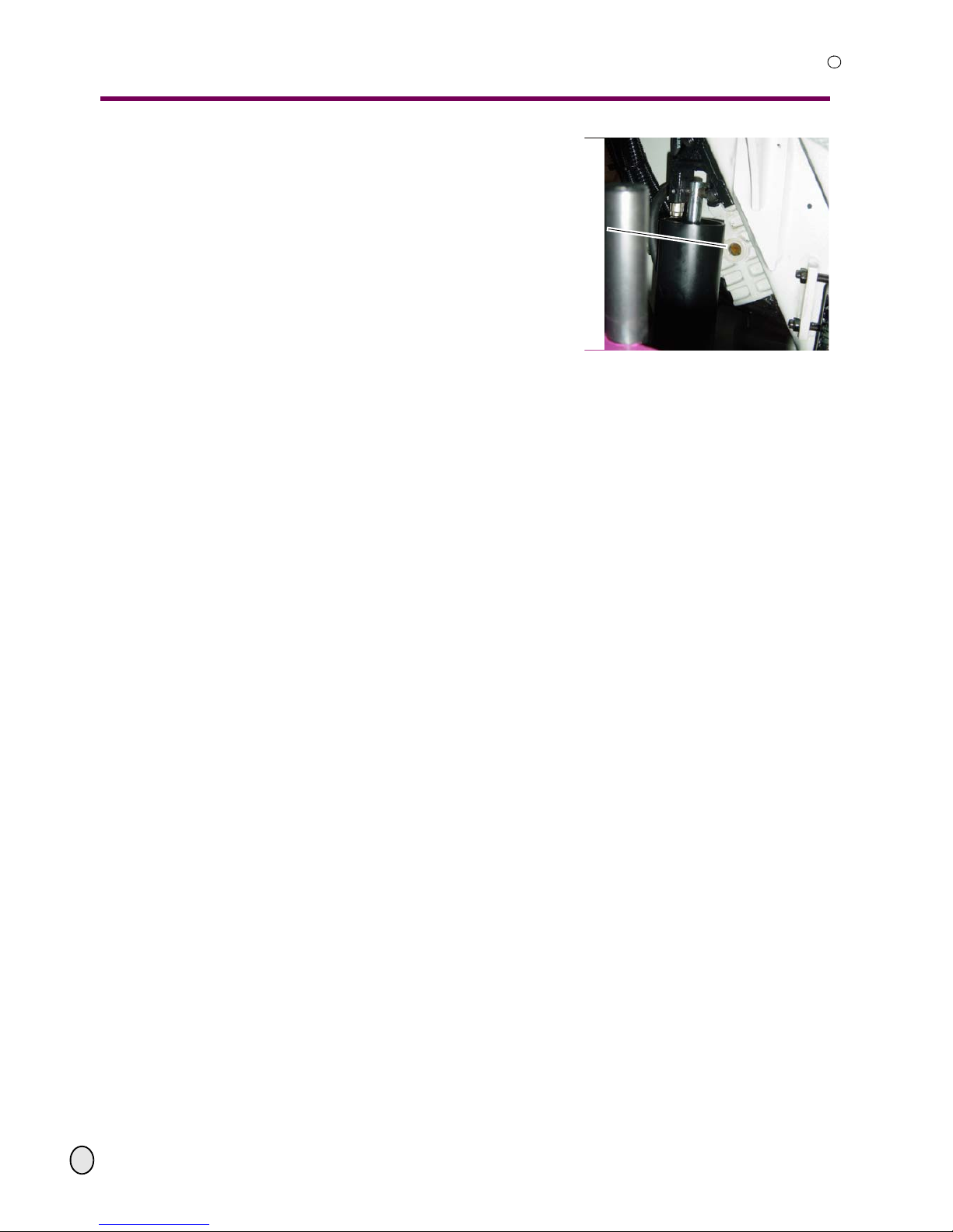
Display of the oil level in the gear
“oil change“ on page 46
Illustr.4-4: oil sight glas gear
Scale for the clearance of the saw blade guidances
Illustr.4-8: “saw blade guide“ on page 35
Scale for adjusting the the cutting angle
Illustr.4-7: “angle cut - 60°“ on page 35
Scale for the depth stop
Illustr.3-40: “depth stop“ on page 27
sight glas
Page 34
Operation
OPTIMUM
MASCHINEN - GERMANY
© 2008
GB
Page 34 Metal belt saw Opti S 300 VG Version 1.1.0 5 February 2008
R
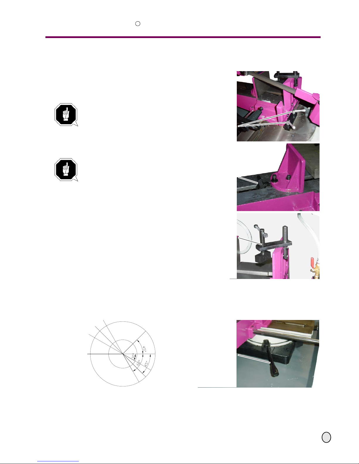
4.3 Inserting the work piece
Close the lowering valve.
Lift the saw arch manually with the han-
dle.
Put the workpiece to be cut into the quick
action vice.
ATTENTION!
Danger of overturning the metal belt saw.
Support long work pieces before pushing the piece to be cut into the quickaction vice.
Open the clamping lever in order to
adjust the vice to the front or to the rear.
ATTENTION!
Push the vice completely forwards or
backwards to the depth stop. In any o ther
position, the lateral saw blade guidances
and the protective covers are being damaged.
Lift the follower, in order to move the jaws
of the vice.
If necessary, use the holddown plate in
order to additionally clamp the workpiece
parts (bundle).
Illustr.4-5: quick action vice
4.3.1 Turn saw bow
Turn the saw bow to the required cutting position. The scale to adjust the angle is on the
bearing support. Secure the adjustment with the clamping lever.
Illustr.4-6: slewing range
clamping lever
follower
holddown plate
clamping lever
Page 35
OPTIMUM
MASCHINEN - GERMANY
Operation
© 2008
GB
Page 355 February 2008 Version 1.1.0 Opti S 300 VG Metal belt saw
R
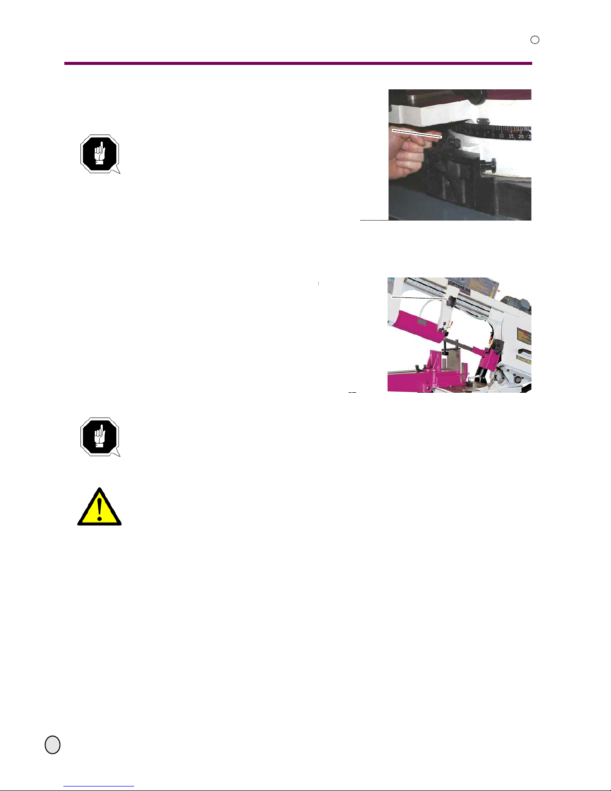
For saw-cuts in the range from 0° to - 60°,
the quick action vice must be pushed forward completely.
ATTENTION!
Push the vice completely forward up to
the depth stop. In any other position,
you may cut into the vice or you may
damage the lateral saw blade guidances and the protective covers.
Illustr.4-7: angle cut - 60°
Raise the stop in order to turn the saw arch in the position from 0° to - 60°.
4.4 Adjusting the saw blade guide
Change the position of the saw blade guide
depending on the size of the pieces to be
cut.
Loosen the clamping screw.
Adjust the width of the saw blade guide
by means of the scale.
Re-tighten the clamping screw.
Illustr.4-8: saw blade guide
ATTENTION!
An unnecessarily wide space between the workpiece an d the saw blade guide in combi-
nation with a high feed rate very quickly causes the saw blade to wear down.
4.5 Switching on the metal belt saw
CAUTION!
Do not wear loose or slack clothes such as for instance an open workcoat when you
switch on the metal belt saw. Follow the safety regulations.
“Control and indicating elements“ on page 31
4.6 Switching off the metal belt saw
During the cutting process
First, close the lowering valve.
Then, switch off the running of the saw blade.
When the material is completely cut, the metal belt saw is automatically switched off by the
depth stop switch. They are then also positioned on the mechanical depth stop.
stop
Adjusting the width of
saw blade guide
Page 36
Operation
OPTIMUM
MASCHINEN - GERMANY
© 2008
GB
Page 36 Metal belt saw Opti S 300 VG Version 1.1.0 5 February 2008
R
4.7 Adjusting the speed of the saw blade
ATTENTION!
The modification of the speed of the
saw blade is to be performed when the
engine of the metal belt saw is running.
Changing the speed in standstill can
cause damage to the variator with serrated belts.
Control the adjustments of the cutting
speed in the display on the control
panel.
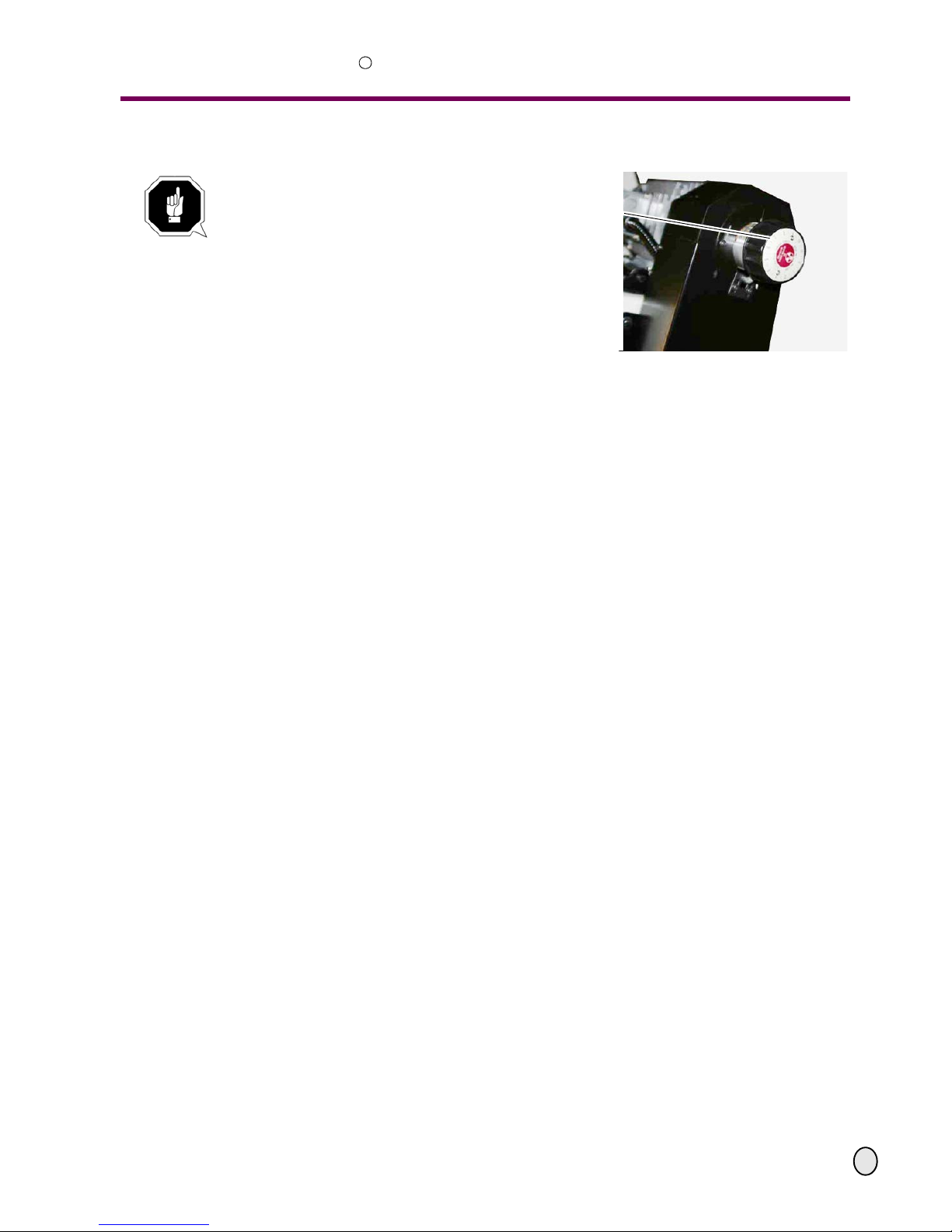
Illustr.4-9: variator
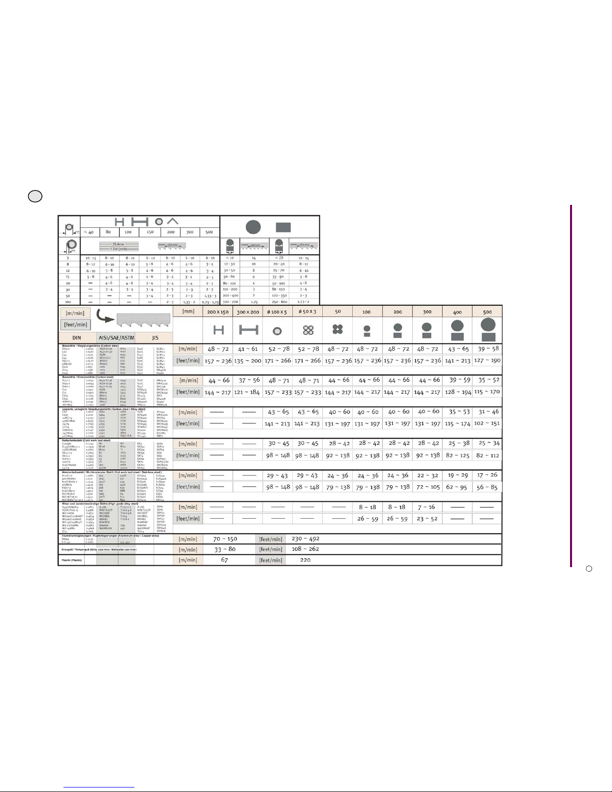
Use the recommended guide numbers.
Use the recommended number of teeth per inch depending on the material to be cut
(exchange of the saw blade).
adjusting the speed of
the saw blade
Page 37
OPTIMUM
MASCHINEN - GERMANY
Operation
© 2008
GB
Page 375 February 2008 Version 1.1.0 Opti S 300 VG Metal belt saw
R
4.7.1 Recommended speed of the saw blade
Page 38

Operation
OPTIMUM
MASCHINEN - GERMANY
© 2008
GB
Page 38 Metal belt saw Opti S 300 VG Version 1.1.0 5 February 2008
R
Chips as an indicator
The sawing chips are the best indicator for the correct adjustment of the feed and the speed of
the saw blade. Have a look at the chips which you have produced and adju st the feed correctly.
4.8 Coolant appliance
ATTENTION!
Failure of the pump in the event of a dry run. The pump is lubricated by the cooling
agent. Do not start up the pump without cooling agent.
If necessary, switch on the coolant appliance on the control panel and dispense the quantity to
be fed with the valves.
4.8.1 Spray gun
Use the spay gun to remove the sawing chips during the cutting proceedure or to lubricate or
to cool down certain areas.
CAUTION!
Do not spray the lubricant or the coolant right next to you.
INFORMATION
We recommend that you use a water-soluble and non-pollutant sawing emulsion as a cooling
agent. This can be acquired from authorised distributors.
Make sure to clean up the cooling agent after use.
Respect the environment when disposing any lubricants and cooling agents.
Follow the manufacturer’s disposal instructions.
4.9 Hydraulic Feed
Adjust the down speed of the saw arch with the feed adjustment valve.
Open the lowering valve.
“Control panel hydraulics“ on page 32
The metal belt saw automatically switches off when you reach your end position.
Thin chips which look like powder.
Increase the feed or reduce the speed of
the saw blade.
Burnt, heavy chips.
Reduce the feed and / or the speed of
the saw blade.
Gathered, silver and warm chips.
• Optimum feed and speed of the saw
blade.
Page 39

OPTIMUM
MASCHINEN - GERMANY
General information concerning saw blades
© 2008
GB
Page 395 February 2008 Version 1.1.0 Opti S 300 VG Metal belt saw
R
5 General information concerning saw blades
In order to achieve an optimum service life with a new saw blade, it is necessary to put the saw
blade carefully into service.
The excessively sharp cutting edges of the saw teeth of a new saw blade are sensitive against
small splinters coming off.
It is recommended to start sawing with up to 50% of the standard cutting pressure and only
increase the cutting pressure to standard level after about 10 to 15 minutes of cutting period
respectively 300-500 cm² of cut edge.
5.1 Spacing
The toothing indicates the number of teeth on one inch (25,4mm).
General rule: The shorter the cutting length, the fin er the toothing, the larger the cutting width,
the rougher the toothing to be used.
For an optimum performance of t he cuttin g operat ion, apart from the stee l quality, the number of
teeth as well as the shaping of the cutting edge is essential.
The geometric shape of the cutting edge and of the tooth root surface is depending on the mate-
rial to be cut and essentially influences the cutting behaviour of the metal belt saw. We recommend you four shapes of teeth to fulfil your cutting requirements:
Full-length tooth
Effective cutting angle 0°: full fillet radius tooth root surface. Universally applicable from little to
middle gross sections, tubes, plates, profile cuts.
Special tooth for gaps
Effective cutting angle 0°: little addendum of tooth, plane tooth root surface. Recommended for
the cutting of rough material of larger cross sections, such as for instance bronze, br ass, zinc,
aluminium cast, rough plastics.
Throat claw
Positive effective cutting angle: with full fillet radius tooth root surface. Advantageous for cutting
of oversized material, i.e. non-ferrous metals, steels with low carbon content, materials with
large cross sections, metal materials which are susceptible to col d-work hardening when cutting.
Combined tooth
Toothing with 0° (N), positive (Plus) or extremely positive (Super Plus). Effective cutting angle:
permanently repeating tooth groups whose teeth within a group have different tooth pitch and
are therewith higher. The interfering oscillations are being reduced with a positive result on the
noise level, the quality of the cut surface and the tool life. The field of application of this toothing
is universal from layer and bundle cut up to the large gross sections of the different metal materials.
Page 40
General information concerning saw blades
OPTIMUM
MASCHINEN - GERMANY
© 2008
GB
Page 40 Metal belt saw Opti S 300 VG Version 1.1.0 5 February 2008
R
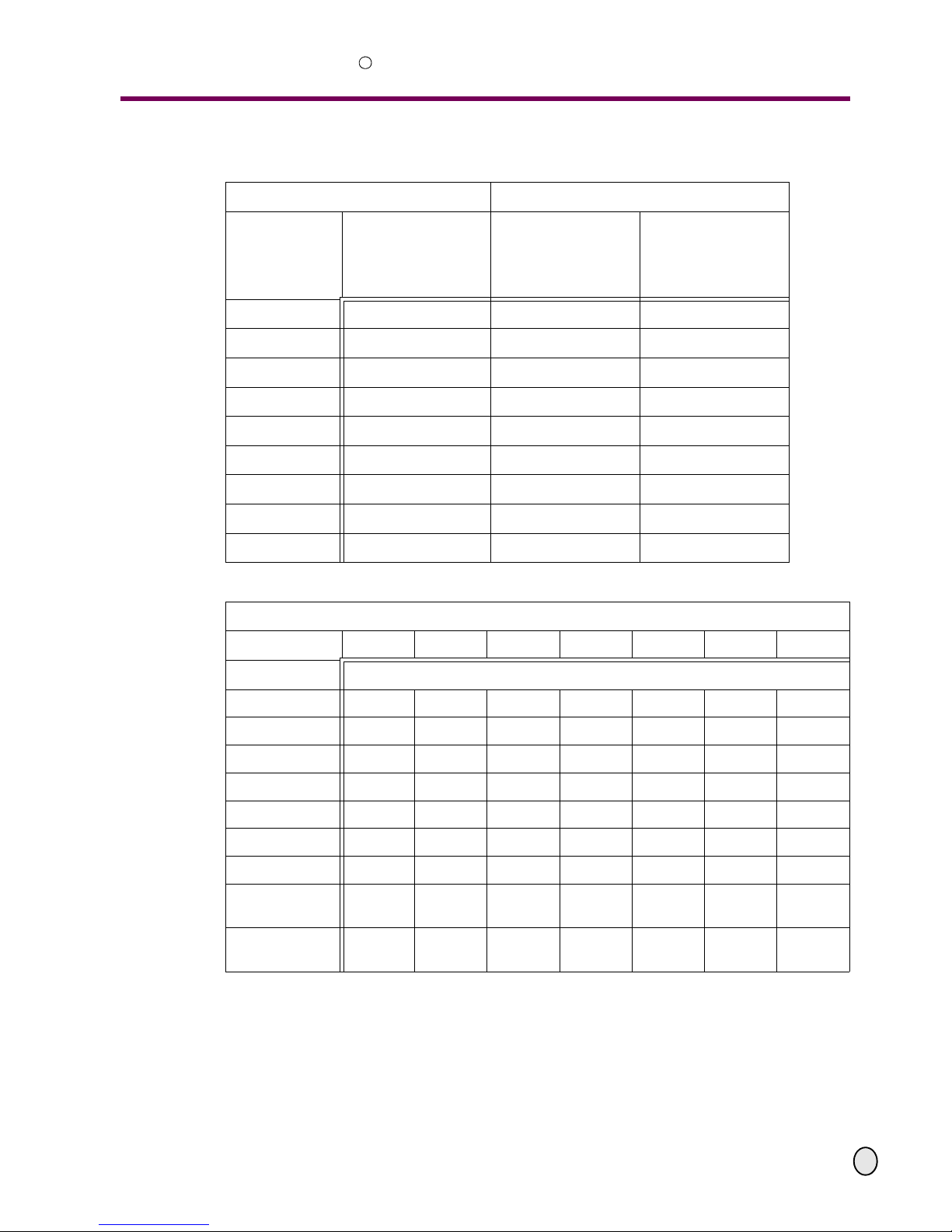
Toothing pitch when using HSS Bi metal bands
Standard toothing Combined toothing
Material
Cross section
[mm]
Number of teeth per
inch with (tooth
shape)
[teeth per inch]
Material
Cross section [mm]
Number of teeth per
inch with (tooth
shape)
[teeth per inch]
< 12 14 (N) < 25 10 - 14 (0°)
12 - 30 10 (N) 20 - 40 8 - 12 (0°)
30 - 50 8 (N) 25 - 70 6 - 10 (0°)
50 - 80 6 (N) 35 - 90 5 - 8 (0°)
80 - 100 4 (Kl.) 50 - 100 4 - 6 (positive)
110 - 200 3 (Kl.) 80 - 150 3 - 4 (positive)
110 - 200 3 (Kl.) 120 - 350 2 - 3 (positive)
200 - 400 2 (Kl.) 250 - 600 1,33 - 2 (positive)
> 400 1,25. (Kl.) 500 - 3000 0,75 - 1,25 (positive)
Cutting of tubes and profiles
Diameter < 40 80 100 150 200 300 500
Wall thickness T ooth pitch
3 8 - 12 8 - 12 8 - 12 8 - 12 6 - 10 6 - 10 6 - 10
8 8 - 12 6 - 10 6 - 10 5 - 8 4 - 6 4 - 6 3 - 4
12 6 - 10 5 - 8 5 - 8 4 - 6 4 - 6 4 - 6 3 - 4
15 5 - 8 4 - 6 4 - 6 4 - 6 3 - 4 3 - 4 2 - 3
20 - 4 - 6 4 - 6 3 - 4 3 - 4 3 - 4 2 - 3
30 - 3 - 4 3 - 4 3 - 4 2 - 3 2 - 3 2 - 3
50 - - - 3 - 4 2 - 3 2 - 3 1,33 - 2
100 - - - - 2 - 3 1,33 - 2
0,75 -
1,25
120 - - - - 1,33 - 2
0,75 -
1,25
0,75 -
1,25
Page 41

OPTIMUM
MASCHINEN - GERMANY
General information concerning saw blades
© 2008
GB
Page 415 February 2008 Version 1.1.0 Opti S 300 VG Metal belt saw
R
5.2 Set of saw teeth
In order to achieve cutting free when sawing, the individual teeth are reciprocally bent off the
blade platform. The kind of set of saw teeth is depending on the cross section of the material to
be cut, the shape of material and the material.
Standard set of saw teeth
Appropriate for sawing all materials when there are at least 3 teeth caming in simultaneously.
Application area from 5mm on.
Set of saw teeth right/left
To saw soft materials (non-ferrous metals, plastics, wood).
Group of set of saw teeth
A development to almost oscillation-free sawing of thin material cross sections, i.e. tubes and
profiles. Due to the inclined teeth in a series of set of saw teeth, smooth cut surfaces for
increased cutting speeds are being achieved.
Wave-shape set of saw teeth
A special set of saw teeth for thinnest material cross sections of up to 5 mm, i.e. thin-walled
tubes, profiles, plates, etc.
Set of saw teeth combined tooth
The groups of teeth which are repeating throughout the band length show one or more straight
teeth whereas the other teeth are sets of cut teeth right / lef t.
Page 42

Maintenance
OPTIMUM
MASCHINEN - GERMANY
© 2008
GB
Page 42 Metal belt saw Opti S 300 VG Version 1.1.0 5 February 2008
R
6 Maintenance
In this chapter you will find important information about
• inspection
• maintenance
•repairs
of the metal belt saw.
ATTENTION!
Properly-performed regular maintenance is an essential pre-requisite for
• safe operation,
• faulty-free operation,
• long service life of the metal belt saw and
• the quality of the products you manufacture.
Installations and equipment for other manufacturers must also be in optimum condition.
ENVIRONMENTAL PROTECTION
Make sure that liquids and oils are not spilt on the ground.
Clean up any spilt liquid or oils immediately using oil-absorption methods and dispose of them in
accordance with current legal requirements on the environment.
Collecting spillages
Do not re-introduce liquids spilt outside the system during repair or as a result of leakage from
the reserve tank: collect them in a collecting vessel to be disposed of.
Disposal
Never dump oil of other pollutant substances in water inlet s, river s or channels.
Used oils must be delivered to a collection centre. Consult your superior if you do not know
where the collection centre is.
6.1 Safety
WARNING!
The consequences of incorrect maintenance and repair work may include:
• Very serious injury to personnel working on the metal be lt saw,
• Damage to the metal belt saw.
Only qualified personnel should carry out maintenance and repair work on the metal belt
saw.
Use the prescribed protection equipment.
6.1.1 Preparation
WARNING!
Only carry out work on the metal belt saw if it has been unplugged from the main power
supply.
“Switching off and securing the metal belt saw“ on page 13. Position a warning sign.
6.1.2 Restarting
Before restarting run a safety check.
“Safety check“ on page 11
Page 43
OPTIMUM
MASCHINEN - GERMANY
Maintenance
© 2008
GB
Page 435 February 2008 Version 1.1.0 Opti S 300 VG Metal belt saw
R
WARNING!
Before connecting the metal belt saw you must check that:
• there is no danger for personnel,
• the metal belt saw is undamaged.
6.2 Revision and maintenance
The type and extent of wear depends to a large extent on the individual usage and service conditions. For this reason, all the intervals are only valid for the authorised conditions.
Intervals /
When?
Where? What? How?
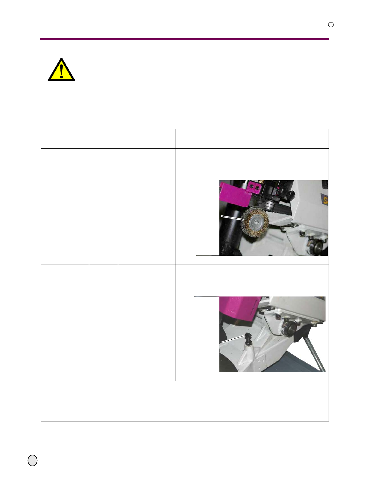
every week
saw blade guidance
saw blade brush
Disassemble the protective cover of the right hand
saw blade guidance
Clean the saw blade brush with a steel brush and
refasten the protective cover.
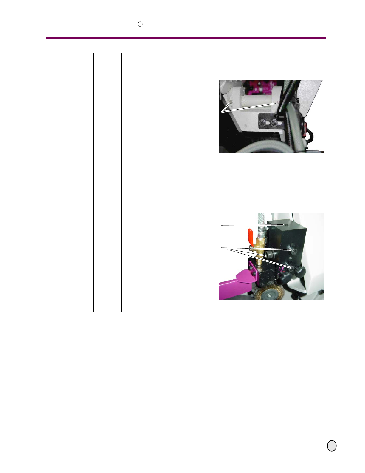
Illustr.6-1: right hand saw blade guidance
as required
bearing bock saw arch
adjusting the end
position
The end position of the saw bade (saw arch) shall be
positioned below the support face of the machine vice.
Adjust the end position of the saw arch with the
screw. Refasten the counternut after readjusting it.
Illustr.6-2: end position saw arch
at the beginning
of every shift
after each main-
tenance or repair
work
Metal belt saw
“Safety check“ on page 11
saw blade brush
Mechanical end posi-
tion of the saw arch
adjusting screw
Page 44
Maintenance
OPTIMUM
MASCHINEN - GERMANY
© 2008
GB
Page 44 Metal belt saw Opti S 300 VG Version 1.1.0 5 February 2008
R
each month
bearing bock
lubricate
Grease with grease gun.
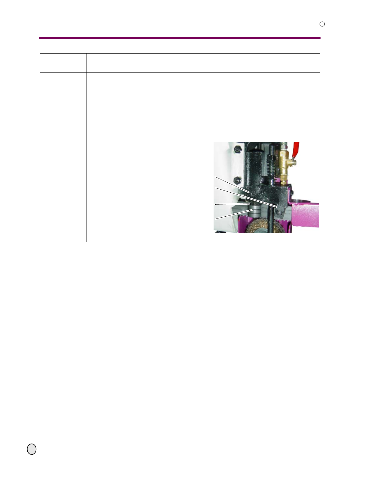
Illustr.6-3: bearing bock
as required and
every six months
upper saw blade guidance
readjust
adjust
control
The rear part of the saw blade shall slightly lie on the
upper pilot bearing. The saw blade is to be tensed dur ing
the readjustment.
Untighten the three clamping screws in order to
adjust the height with the set screw. The rear side of
the saw blade must only be slightly in contact with the
upper pilot bearing.
Illustr.6-4: right hand saw blade guidance
Intervals /
When?
Where? What? How?
lubricating nipple
set screw
clamping screws
Page 45
OPTIMUM
MASCHINEN - GERMANY
Maintenance
© 2008
GB
Page 455 February 2008 Version 1.1.0 Opti S 300 VG Metal belt saw
R
as required and
every six months
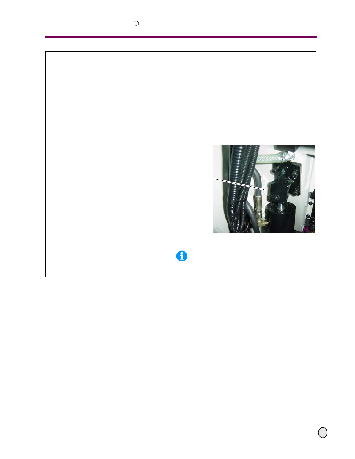
lateral saw blade guidance
saw blade guidances
readjust
adjust
control
The sides of the saw blade shall slightly lie on the pilot
bearing. During the readjustment, the saw blade is to be
tensed.
Unfasten the stud screw of the rear pilot bearing in
order to adjust the lateral clearance. The rear pilot
bearing is equipped by an excenter.
Also readjust the sliding bearing.
Proceed in the same way for the adjustment of the
saw blade guidances.
Illustr.6-5: right hand saw blade guidance, rear
Intervals /
When?
Where? What? How?
stud screw
sliding bearing
hexagon with excenter
rear pilot bearing
Page 46
Maintenance
OPTIMUM
MASCHINEN - GERMANY
© 2008
GB
Page 46 Metal belt saw Opti S 300 VG Version 1.1.0 5 February 2008
R
first after 50 oper-
ating hours, then
every six months
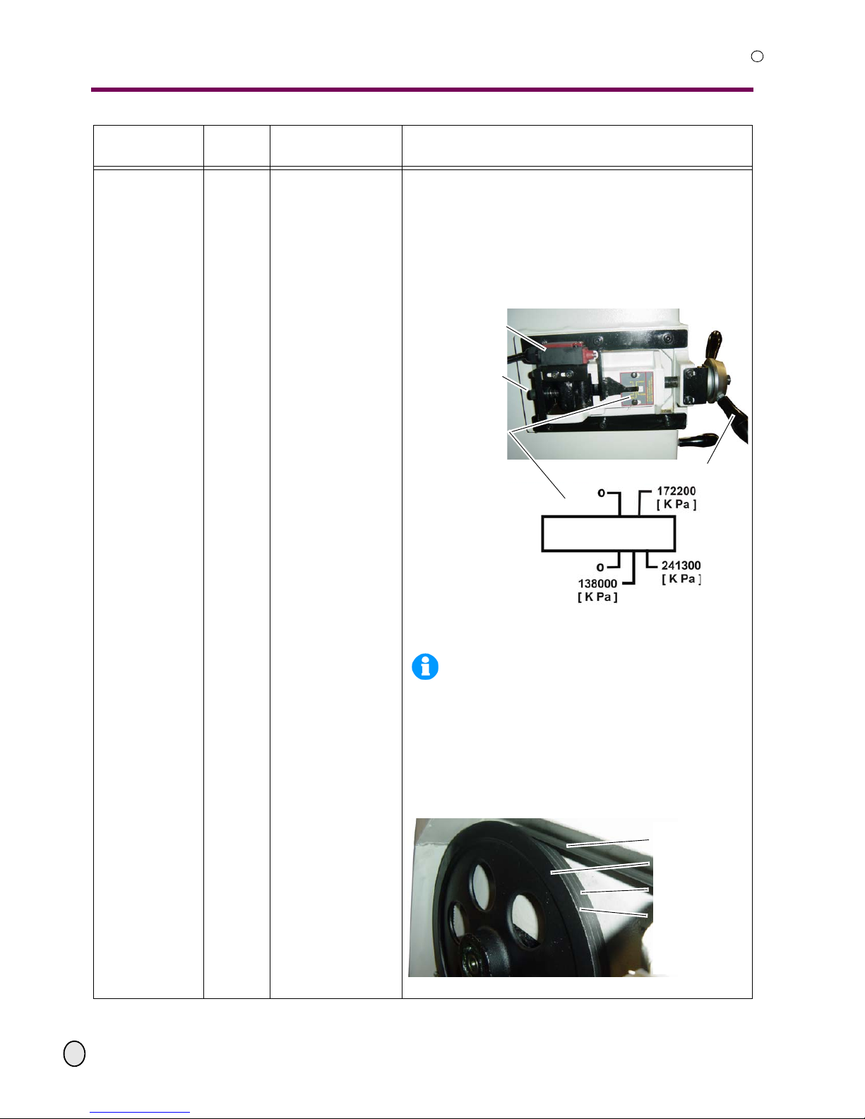
gear
oil change
The gear is filled with the high-performance gear oil
Mobilgear 636, viscosity 680 mm2/sec.
Lift the saw arch completely.
Remove the drain plug at the bottom end of the gear.
Use an adequate vessel with enough capacity to collect the oil.
Open the fuel filler cap for a better ventilation.
Fill the gear up to the upper mark of the sight glass
with the saw arch completely lowered.
Illustr.4-4:
“oil sight glas gear“ on page 33
Illustr.6-6: gear
INFORMATION
Run the metal belt saw a few minutes before
you start the oil change. The oil warms up and
flows more easily through the outlet.
Intervals /
When?
Where? What? How?
screw plug
charging hole
Page 47
OPTIMUM
MASCHINEN - GERMANY
Maintenance
© 2008
GB
Page 475 February 2008 Version 1.1.0 Opti S 300 VG Metal belt saw
R
as required and
after changing
the saw blade
saw arch
Adjusting the tension
of the saw blade
Adjusting the posi-
tion of the saw blade
on the saw blade pul-
leys.
The saw blade is being tensed with the handwheel.
Turn the handwheel clockwise to increase the ten-
sion in the saw blade.
The saw blade is at the right tension when the mark-
ing coincides with the scale.
• 138 000 KPa [ kilo pascal or Kilo -N/m2] for standard metal
saw blades.
• from 172 200 up to 241 300 KPa for bi-metal saw blades.
Illustr.6-7: tension of the saw blade
INFORMATION
Do not strain the saw blade more than necessary. The blade could be overstretched and
become warped.
The saw blade must fit on the shoulder of the two
saw blade pulleys when running.
Use the "set screw for the saw blade pulley" in order
to adjust the position of the saw blade pulley, if the
rear side of the saw blade does not touch or fit on the
step of the saw blade pulleys when running.
Illustr.6-8: saw blade pulley
Intervals /
When?
Where? What? How?
position switch
saw blade
set screw
saw blade pulley
scale for saw blade
adjustment
handwheel for the tension of the saw blade
saw blade
saw blade pulley
running surface
shoulder
Page 48
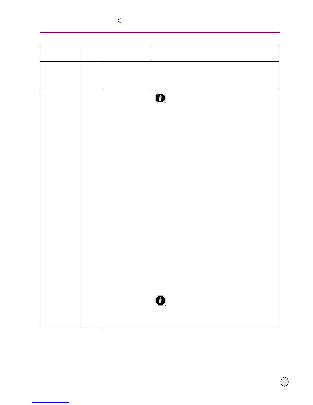
Maintenance
OPTIMUM
MASCHINEN - GERMANY
© 2008
GB
Page 48 Metal belt saw Opti S 300 VG Version 1.1.0 5 February 2008
R
every month
work holder
vice
lubricate
Lubricate the spindle of the machine vice.
as required
depending on
wear
saw arch
exchange of the saw
blade
ATTENTION!
This metal belt saw is constructed for saw
blades with the dimensions 27 x 0,9 x 3352.
The use of other saw blades may lead to
worse cutting results.
Lift the saw arch to about the half height and close
the lowering valve.
Turn the saw arch to the right.
Secure the metal belt saw against unauthorized use.
“Switching off an d securing the metal belt saw“ on
page 13
Open the cover of the saw arch and disassemble the
covers of the saw blade guidances.
Loosen the saw blade tension by turning the hand-
wheel anticlockwise.
First lift the saw blade of the lef t blade pulley and then
of the driven blade pulley.
Clean the complete saw blade area.
Proceed the opposite way to assemble the new saw
blade. Make sure that the saw blade is positioned
correctly onto the blade pulleys and in the blade guidance bearings.
Make sure that the saw teeth show to the right direc-
tion. The saw teeth must show to the driving motor.
Retighten the saw blade.
If required, readjust the saw blade guidances.
“saw blade guidances readjust“ on page 45
Close the saw blade housing.
Proceed a trial run.
Remount all the protective covers.
ATTENTION!
In order to achieve an optimum service life of
the new saw blade, it is necessary to carefully run in the saw blade.
“General information concerning saw
blades“ on page 39
Intervals /
When?
Where? What? How?
Page 49
OPTIMUM
MASCHINEN - GERMANY
Maintenance
© 2008
GB
Page 495 February 2008 Version 1.1.0 Opti S 300 VG Metal belt saw
R
6.3 Repair
For any repair work, get assistance from an employee of Optimum Maschinen GmbH’s technical service or send us the metal belt saw.
If the repairs are carried out by qualified technical staff, they must follow the indications given in
this manual.
Optimum Maschinen GmbH does not take responsibility nor does it guarantee against damage
and operating anomalies resulting from failure to observe this manual.
For repairs, only use
• faulty-free and suitable tools,
• original spare parts or parts from series expressly authorised by Optimum Maschinen GmbH.
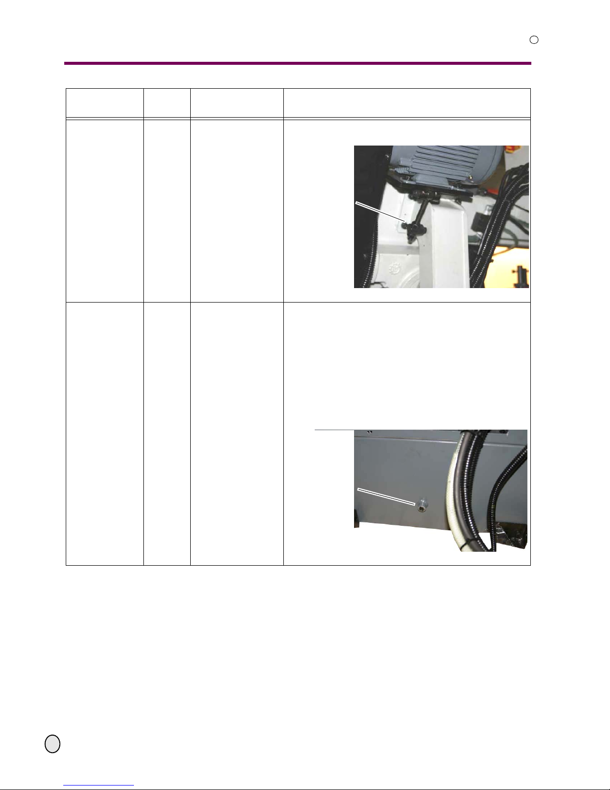
as required,
after exchange of
the toothed belt
drive motor
adjust
control
When the toothed belt is too loose on the pulleys,
retighten it.
Illustr.6-9: drive motor
when the coolant
is used and dirty
liquid cooling system
replace
The cooling pump is almost entirely maintenance-
free. Replace the cooling agent regularly, depending
on usage.
When using coolants which leave residues, the cool-
ing pump must be washed.
Pump the coolant to an adequate vessel by the spray
gun. Let the remenant coolant drain through the outlet.
Fill in new coolant over the chip pan. The maximum
capacity of the coolant is 30 litres.
Illustr.6-10: coolant container
Intervals /
When?
Where? What? How?
clamping screw
on the engine
outlet
Page 50
Ersatzteile - Spare parts S300 VG
OPTIMUM
MASCHINEN - GERMANY
R
50
S:\Betriebsanleitungen\saws\S300VG\S300VG_parts\S300VG_parts.fm
5.2.08
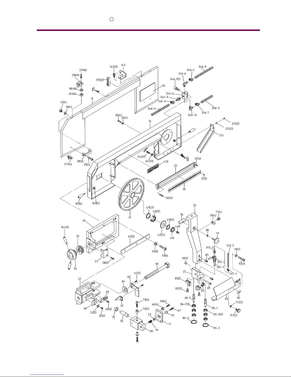
7 Ersatzteile - Spare parts S300 VG
7.1 Zeichnung - Explosion drawing - S300 VG
Page 51

OPTIMUM
MASCHINEN - GERMANY
Ersatzteile - Spare parts S300 VG
R
5.2.08
S:\Betriebsanleitungen\saws\S300VG\S300VG_parts\S300VG_parts.fm
51
7.2 Zeichnung - Explosion drawing - S300 VG
Page 52
Ersatzteile - Spare parts S300 VG
OPTIMUM
MASCHINEN - GERMANY
R
52
S:\Betriebsanleitungen\saws\S300VG\S300VG_parts\S300VG_parts.fm
5.2.08
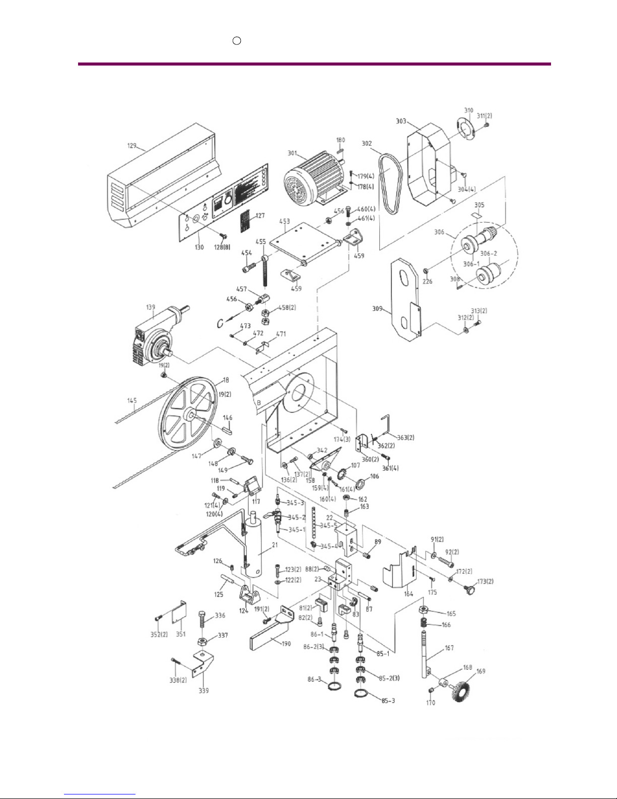
7.3 Zeichnung - Explosion drawing - S300 VG
Page 53
OPTIMUM
MASCHINEN - GERMANY
Ersatzteile - Spare parts S300 VG
R
5.2.08
S:\Betriebsanleitungen\saws\S300VG\S300VG_parts\S300VG_parts.fm
53
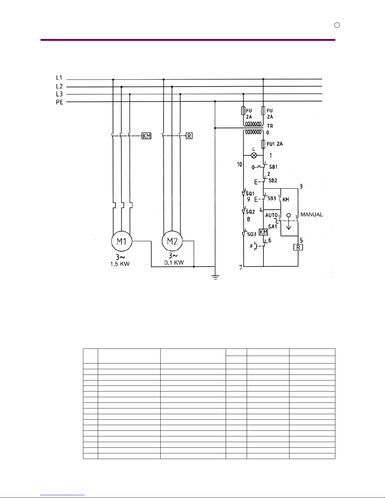
7.3.1 Schaltplan - Wiring diagram - S300 VG
7.3.2 Ersatzteilliste - Spare parts list - S300 VG
Pos.
Bezeichnung Designation
Menge Grösse Artikelnummer
Qty. Size Item no.
1 Unterbau Stand 1 0329030001
1-1 Abdeckung Cover 1 0329030001-1
1-2 Schraube Cross Round Head Screw 4 M6x15
1-3 Platte Hanger Plate 4 0329030001-3
2 Schwenkplatte Swivel Arm Base 1 0329030002
5 Schwenkarm Swivel arm 1 0329030005
6 Halter Rear Pivot Bracket 1 0329030006
7 Schraubstock Vise Base 1 0329030007
9 Backe Vise Jaw Bracket 1 0329030009
10 Flansch Fixed Shaft 1 0329030010
11 Aufnah meplatte Schraubstock Slide Base 1 0329030011
13 Backe Vise Jaw Bracket 1 0329030013
14 Sägebügel Saw bow 1 0329030014
16 Sägebandabdeckung Blade Back Cover 1 0329030016
17 Zwischenrad Idler Wheel 1 0329030017
18 Antriebsrad Drive Wheel 1 0329030018
19 Schraube Hex. Head Screw 2 M12x10
Page 54

Ersatzteile - Spare parts S300 VG
OPTIMUM
MASCHINEN - GERMANY
R
54
S:\Betriebsanleitungen\saws\S300VG\S300VG_parts\S300VG_parts.fm
5.2.08
21 Hydraulikzylinder Hydraulic cylinder 1 0329030021
22 Arm Arm 1 0329030022
23 Sägebandeinstellung Blade Adjustable 1 0329030023
24 Arm Arm 1 0329030024
25 Lagerbock Bearing block 1 0329030025
26 Bandeinstellung Blade Angle Adjusting Bracket 1 0329030026
27 Bandeinstellung Blade Tension Sliding Plate 1 0329030027
28 Rahmen Anchor Block 1 0329030028
29 Skalenaufnahme Scale collet 1 0329030029
30 Skala Scale 1 0329030030
31 Niete Rivet 2 Ø2x5 0329030031
32 Schraube Hex. Socker Headless Screw 4 M8x20
33 Schraube Hex. Socket Head Screw 2 M12x20
34 Label Blade Select Chart 1 0329030034
35 Unterlegscheibe Spring Washer 4 M6
36 Schraube Cross Round Head Screw 4 M6x10
37 Schraube Hex. Socket Head Screw 4 M8x20
38 Griff Grip 2 0329030038
39 Scheibe Washer 4 M8
40 Schraube Hex. Nut 4 M8
49 Leiste Gib 2 0329030049
50 Scheibe Spring Washer 6 M8
51 Schraube Hex. Socket Head Screw 6 M8x40
52 Scheibe Washer 2 M5
53 Scheibe Washer 1 M10
54 Feder Spring 1 0329030054
55 Kugellager Ball bearing 1 51204 04051204.2R
56 Aufnahme Handle Body 1 0329030056
57 Halter Bracket 1 0329030057
58 Schraube Cross Round Head Screw 2 M5x10
59 Schalterplatte Switch Base 1 0329030059
60 Schraube Cross Round Head Screw 2 M5x10
61 Anzeige Pointer 1 0329030061
62 Platte Plate 1 0329030062
63 Schraube Cross Round Head Screw 2 M4X20
64 Bolzen Bolt 1 0329030064
65 Schraube Cross Round Head Screw 2 M5x8
66 Platte Tension Indicating Plate 1 0329030066
67 Schraube Hex. Socket Head Screw 1 M10x40
68 Schraube Hex. Socket Head Screw 4 M6x15
69 Scheibe Spring Washer 4 M6
70 Hülse Hemicycle Washer 1 0329030070
71 Platte Plate 1 0329030071
72 Buchse Shaft Bushing 2 0329030072
73 Schraube Hex. Socket Head Screw 2 M6x25
74 Welle Shaft 1 0329030074
75 Hülse Bushing 1 0329030075
76 Schlauchklemme Hose Clamp 4 Ø12 0329030076
77 Schraube Cross Round Head Screw 4 M5x10
78 Leiste Gib 1 0329030078
79 Einstellknopf Blade Adjustable Knob 1 0329030079
80 Scheibe Washer 1 M10
81 Führung Carbide Guide 4 0329030081
82 Schraube Hex. Socket Head Screw 4 M6x20
83 Kugellager Ball bearing 2 609ZZ 040609.2R
84 Scheibe Disc Spring 1 0329030084
85 Lagerbolzen komplett Bearing Shaft Assembly 2 0329030085CPL
85-1 Lagerbolzen Bearing Shaft 2
85-2 Kugellager Ball bearing 6 609ZZ 040609.2R
85-3 Sicherungsring C-Retainer Ring 2
86 Lagerbolzen komplett Eccentric Shaft Assembly 2 0329030086
86-1 Lagerbolzen Eccentric Shaft 2 0329030086-1
86-2 Kugellager Ball bearing 6 609ZZ 040609.2R
86-3 Sicherungsring C-Retainer Ring 2
87 Stift Bearing Pin 2 0329030087
88 Schraube Hex. Socker Headless Screw 4 M5x10
89 Schraube Hex. Socker Headless Screw 2 M6x10
90 Schraube Hex. Socket Head Screw 2 M8x20
91 Schraube Washer 4 M8
Pos.
Bezeichnung Designation
Menge Grösse Artikelnummer
Qty. Size Item no.
Page 55

OPTIMUM
MASCHINEN - GERMANY
Ersatzteile - Spare parts S300 VG
R
5.2.08
S:\Betriebsanleitungen\saws\S300VG\S300VG_parts\S300VG_parts.fm
55
92 Schraube Hex. Socket Head Screw 4 M8x25
93 Bandabdeckung Blade guard 1 0329030093
94 Label Label 1 0329030094
95 Scheibe Spring Washer 4 M12
96 Schraube Hex. Socket Head Screw 4 M12x40
98 Schraube Hex. Socket Head Screw 4 M10x30
101 Schraube Hex. Socket Head Screw 4 M10x35
102 Scheibe Spring Washer 4 M10
103 Schraube Hex. Socket Head Screw 4 M10x20
104 Scheibe Spring Washer 4 M10
105 Scheibe Washer 4 M10
106 Mutter Nut 2 AN07 03290300106
107 Scheibe Washer 2 AW07 03290300107
108 Buchse Bushing 1 03290300108
109 Schraube Hex. Socket Head Screw 2 M10x40
110 Scheibe Washer 3 M16
111 Halter Bracket 1 03290300111
112 Zahnhaken Rack Hook 1 03290300112
113 Stift Pin 1 03290300113
114 Schraube Hex. Socker Headless Screw 2 M6x10
115 Handrad Handwheel 1 03290300115
117 Zylinderhalter Cylinder Upper Support 1 03290300117
118 Stift Pivot Pin 1 03290300118
119 Schraube Hex. Socker Headless Screw 1 M6x10
120 Scheibe Washer 4 M8
121 Schraube Hex. Socket Head Screw 4 M8x20
122 Scheibe Spring Washer 2 M8
123 Schraube Hex. Socket Head Screw 2 M8x20
124 Zylinderhalter Cylinder Lower Support 1 03290300124
125 Stift Pivot Pin 1 03290300125
126 Schraube Hex. Socker Headless Screw 1 M6x10
127 Label Name Plate 1 03290300127
128 Schraube Cross Round Head Screw 8 M5x10
129 Schaltergehäuse Control Box 1 03290300129
130 Schaltereinheit Cylinder Control Panel 1 03290300130
131 Klemmblock Protractor Locating Block 1 03290300131
132 Stift Bearing Pin 1 03290300132
136 Scheibe Washer 2 M8
137 Schraube Hex. Socket Head Screw 2 M8X20
139 Getriebe Gear Box Assembly 1 03290300139
140 Mutter Hex. Nut 2 3/8" 03290300140
141 Griff Grip 2 03290300141
142 Schraube Cross Round Head Screw 2 M5x10
143 Platte Bracker 1 03290300143
144 Griff Grip 2 03290300144
145 Sägeband Blade 1 27x0.9x3353
146 Passfeder Key 1 7x7x30 03290300146
147 Scheibe Washer 1 M10
148 Scheibe Spring Washer 1 M10
149 Schraube Hex. Head Screw 1 M10x25
150 Platte Base Support 2 03290300150
151 Scheibe Spring Washer 2 M8
152 Schraube Hex. Socket Head Screw 2 M8x20
153 Schraube Hex. Socker Headless Screw 2 M8x10
158 Halter Bracket 1 03290300158
159 Scheibe Spring Washer 4 M10
160 Scheibe Washer 4 M10
161 Schraube Hex. Socket Head Screw 4 M10x20
162 Mutter Hex. Nut 1 M8
163 Schraube Hex. Socker Headless Screw 1 M8x25
164 Sägebandschutz Blade Guard 1 03290300164
165 Mutter Hex. Nut 1 M10
166 Feder Spring 1 03290300166
167 Welle Brush Shaft 1 03290300167
168 Buchse Bushing 1 03290300168
169 Spänebürste Brush 1 03290300169
170 Schraube Hex. Socker Headless Screw 1 M6x8
172 Scheibe Washer 4 M6
173 Schraube Plum Screw 4 M6x10 03290300173
Pos.
Bezeichnung Designation
Menge Grösse Artikelnummer
Qty. Size Item no.
Page 56
Ersatzteile - Spare parts S300 VG
OPTIMUM
MASCHINEN - GERMANY
R
56
S:\Betriebsanleitungen\saws\S300VG\S300VG_parts\S300VG_parts.fm
5.2.08
174 Schraube Hex. Socket Head Screw 3 M10x20
175 Schraube Cross Round Head Screw 1 M5X8
178 Scheibe Washer 4 M8
179 Schraube Hex. Head Screw 4 M8x15
180 Passfeder Key 1 7x7x35 03290300180
181 Anschlag Stop Block Support 1 03290300181
182 Klemmschraube Clamping screw 1 03290300182
183 Platte Distance Set Bracket 1 03290300183
184 Mutter Hex. Nut 1 M10
185 Schraube Hex. Head Screw 1 M10x30
186 Anschlagbolzen Distance Set Rod 1 03290300186
190 Bandabdeckung Blade Guard II 1 03290300190
191 Schraube Cross Round Head Screw 2 M5x10
195 Scheibe Spring Washer 1 M8
196 Schraube Hex. Socket Head Screw 1 M8x45
197 Mutter Hex. Nut 1 M12
198 Schraube Screw 1 03290300198
205 Halter Rack Support 2 03290300205
209 Scheibe Spring Washer 4 M8
210 Schraube Hex. Socket Head Screw 4 M8x20
211 Zahnstange Rack 1 03290300211
212 Passfeder Key 1 5X5X15 03290300212
213 Spindel Spindle 1 03290300213
214 Halter Feed Support 1 03290300214
215 Scheibe Washer 1 M12
216 Mutter Hex. Nut 1 M12
217 Scheibe Spring Washer 3 M8
218 Schraube Hex. Socket Head Screw 3 M8x20
219 Ösenbolzen Eye Bolt 1 03290300219
220 Feder Spring 1 03290300220
221 Klemmplatte Swivel Arm Briquette 1 03290300221
226 Scheibe Washer Ring 1 03290300226
229 Ring Ring 1 03290300229
230 Welle Pivot Shaft 1 03290300230
231 Kugellager Ball bearing 2 32007 04032007.2R
232 Schraube Hex. Socket Head Screw 4 M10x35
233 Abstandsring Gap Ring 2 03290300233
234 Skala Scale 1 03290300234
235 Niete Rivet 2 Ø2x5 0329030031
240 Stift Pin 2 Ø5x20 03290300240
241 Schraube Hex. Head Screw 2 M8x25
242 Scheibe Washer 2 M8
243 Klemmanschlag Angle Position 1 03290300243
244 O-Ring O-Retainer Ring 4 03290300244
246 Schraube Hex. Head Screw 2 M8x20
247 Mutter Hex. Nut 2 M8
253 Winkelstopper Angle Margin 2 03290300253
254 Schraube Hex. Socket Head Screw 4 M8x20
259 Schraube Hex. Head Screw 1 M6x10
260 Mutter Hex. Nut 1 M6
261 Sieb Filter 1 03290300261
263 Klemmschraube Clamping screw 2 M10x40 03290300263
264 Buchse Bushing 2 Ø19xØ11x5t 03290300264
265 Faltebock Fix Block 1 03290300265
266 Block 2 Way Limit Block 2 03290300266
267 Scheibe Spring Washer 4 M6
268 Schraube Hex. Socket Head Screw 4 M6x20
269 Kühlmittelpumpe Cooling Pump 1 1/8HP/400V/3PH 03290300269
270 Schraube Hex. Head Screw 4 M6x15
271 Scheibe Spring Washer 4 M6
272 Dichtung Rubber Cushion 1 03290300272
277 Schraube Hex. Head Screw 4 M12x50
278 Mutter Hex. Nut 4 M12
279 Spritzwand Splash Board 1 03290300279
280 Spänewanne Chip Tray 1 03290300280
282 Standfuss links Locating Foot (Left) 2 03290300282
284 Standfuss rechts Locating Foot (Right) 2 03290300284
285 Scheibe Washer 8 M8
286 Scheibe Washer 8 M8x15
Pos.
Bezeichnung Designation
Menge Grösse Artikelnummer
Qty. Size Item no.
Page 57
OPTIMUM
MASCHINEN - GERMANY
Ersatzteile - Spare parts S300 VG
R
5.2.08
S:\Betriebsanleitungen\saws\S300VG\S300VG_parts\S300VG_parts.fm
57
290 Seitenfuss Side Leg 1 03290300290
292 Scheibe Washer 8 M8
293 Schraube Hex. Socket Head Screw 8 M8x15
301 Motor Motor 1 2HP/400V/50HZ/3PH 03290300301
302 Keilriemen V-Belt 1 (1422) 360V 03290300302
303 Motorabdeckung Motor Pulley Cover 1 03290300303
304 Schraube Cross Round Head Screw 4 M5x10
305 Label Speed Label 1 E=1/30 03290300305
306 Riemenscheibe Spindle Pulley 1 0329 0300306CPL
306-1 Riemenscheibe Spindle Pulley 1 2HP ØØ24
306-2 Riemenscheibe Variable Speed Pulley 1 2HP Ø24
308 Passfeder Key 1 7x7x30 03290300308
309 Abdeckung Pulley Lower Cover 1 03290300309
310 Abdeckung Cover 1 03290300310
311 Schraube Cross Round Head Screw 2 M5x5
312 Scheibe Washer 2 M6
313 Schraube Hex. Socket Head Screw 2 M6x10
324 Mutter Hex. Nut 3 M10
325 Schraube Hex. Head Screw 3 M10x40
336 Schraube Hex. Head Screw 1 M10x40
337 Mutter Hex. Nut 1 M10
338 Schraube Hex. Socket Head Screw 2 M5x15
339 Führungshalter Lower Adjusting Support 1 03290300339
340 Deflektor Guide Board 1 03290300340
342 Abstandsring Gap Ring 1 03290300342
344 Sprühpistole Spray Assembly 1 03290300344CPL
344-1 Verbindungselement Straight Connector 1 PT3/8"xPT3/8"
344-2 Verteilerdose 3 Way Connector 1 PT3/8"xPT3/8"Xpt3/8"
344-3 Verbindungselement Straight Connector 1 PT3/8"x1/2"
344-4 Verbindungselement Micro Control Block 1 PT3/8"x1/2"
344-5 Schlauchklemme Hose Clamp 3 Ø19
344-6 Schlauch Net Tube 1 ID1/2"x2.8tx126cm
344-7 Schlauch Net Tube 1 ID1/2"x2.8tx320cm
344-8 Sprühpistole Spray 1
345 Ventil Valve Assembly 2 03290300345CPL
345-1 K-Rohr Copper Tube 2 1/4"x4.2cm
345-2 Kugelhahn Valve 2 PT1/8"x1/8"
345-3 Verbindungselement Straight Connector 2 PT1/8"x1/4"
345-4 Schlauchklemme Hose Clamp 2 Ø12
345-5 Schlauch Net Tube 2 ID1/4"x2.2tx143cm
346 Verteiler 3 Way Valve Assembly 1 03290300346CPL
346-1 I nnensechskantschraube Hex. Socket Head Screw 2 M6x30
346-2 Verteilerdose 3 Way Valve 1
346-3 Verbindungselement Straight Connector 1 PT1/4"x1/4"
346-4 Schlauchklemme Hose Clamp 2 Ø12
346-5 Schlauch Net Tube 1 ID1/4"x2.2tx143cm
346-6 Verbindungselement Micro Control Block 1 PT1/4"x1/4"
346-7 Schlauchklemme Hose Clamp 1 Ø19
346-8 Schlauch Net Tube 1 ID1/4"x2.2tx64cm
346-9 Schlauch Net Tube 1 ID1/2"x2.8tx320cm
346-10 Verbindungselement Micro Control Block 1 PT1/4"x1/2"
351 Schalterplatte Switch Bracket 1 03290300351
352 Schraube Hex. Socket Head Screw 2 M6x10
360 Halter Bracket 2 03290300360
361 Schraube Hex. Socket Head Screw 4 M6X10
362 Feder Twisted Spring 2 03290300362
363 Haltestange Support Rod 2 03290300363
370 Halter Bracket 2 03290300370
371 Spänetafel Splash Board 1 03290300371
372 Scheibe Washer 2 03290300372
373 Schraube Cross Round Head Screw 2 03290300373
377 Ring Ring 4 03290300377
378 Scharnier Hinge 3 03290300378
379 Schraube Hex. Socket Head Screw 6 M6X20
383 Mutter Hex. Nut 6 M6
384 Scheibe Washer 6 M6
394 Schraube Hex. Head Screw 1 M8x20
395 Platte Fixed Plate 1 03290300395
396 Scheibe Washer 2 M8
Pos.
Bezeichnung Designation
Menge Grösse Artikelnummer
Qty. Size Item no.
Page 58
Ersatzteile - Spare parts S300 VG
OPTIMUM
MASCHINEN - GERMANY
R
58
S:\Betriebsanleitungen\saws\S300VG\S300VG_parts\S300VG_parts.fm
5.2.08
397 Schraube Hex. Head Screw 2 M8x15
398 Mutter Nut 2 M8
411 Schraube Hex. Head Screw 8 M8x15
413 Mutter Hex. Nut 8 M8
414 Scheibe Washer 8 M8
415 Sicherungsring C-Retaniner Ring 2 03290300415
416 Lager Taper Roller Bearing 2 30205J 04030205.2R
417 Abdeckung Cover 2 03290300417
418 Scheibe Star Washer 2 AW05 03290300418
419 Mutter Nut 1 03290300419
420 Schmeirnippel Grease Nipple 1 PT1/8 03290300420
421 Bolzen Bolt 1 03290300421
422 Aufnahme Bracket 1 03290300422
423 Hebel Lever 1 03290300423
424 Knopf Knob 1 03290300424
430 Halter Limit Switch Adjusting Bracket 1 03290300430
431 Welle Shaft 1 03290300431
432 Anzeiger Pointer 1 03290300432
433 Knopf Knob 1 1/4"X12 03290300433
434 Federscheibe Spring Washer 2 M8
435 Innensechskantschraube Hex. Socket Head Screw 2 M8x10
441 Knopf Knob W/Shaft 2 03290300441
442 Stift Position pin 1 03290300442
443 Welle Shaft 1 03290300443
444 Leiste Gib 1 03290300444
445 Halter Bracket 1 03290300445
446 Stange Rod 1 03290300446
447 Schraube Hex. Socket Flat Head S 1 M6x15
448 Platte Plate 1 03290300448
449 Label Cylinder Control Indicating 1 03290300449
450 Knopf Knob 1 03290300450
451 Knopf Knob 1 03290300451
452 Stift Pin 1 03290300452
453 Motorplatte Motor Plate 1 03290300453
454 Schraube Hex. Socket Head Screw 1 M10x60
455 Welle Shaft 1 03290300455
456 Mutter Hex. Nut 2 M10
457 Welle Shaft 1 03290300457
458 Mutter Hex. Nut 2 M12
459 Motorplatte Motor Bracket 2 03290300459
460 Schraube Hex. Head Screw 4 M6x20
461 Scheibe Washer 4 M6x20
468 Platte Connecting Plate 4 03290300468
469 Scheibe Spring Washer 16 M8
470 Schraube Hex. Socket Head Screw 16 M8x15
471 Schalterhalter Switch Bracket 1 03290300471
472 Scheibe Washer 1 Ø 6.3 x Ø 13 x t 1.2
473 Schraube Hex. Socket Head Screw 1 M6x10
474 Schraube Cross Round Head Screw 2 03290300474
475 Schalterplatte Switch plate 1 03290300475
476 Scheibe Washer 2 03290300476
477 Schraube Hex. Head Screw 2 03290300477
478 Label Name Plate 1 03290300478
479 Abdeckung Anti-Chip Cover 1 03290300479
KM Schütz Contactor 1 LCIK0910B7 03290300KM
R Relais Relay 1 RT424524 03290300R
L Betriebskontrollleuchte Operation control light 1 XB7-EV67 03290300L
TR Transformator Transformer 1 03290300TR
SA1 Schalter Pumpe Pump Switch 1 XB7-ED33 03290300SA1
SB1 Not-aus Schlagschalter Emergency Off switch 1 XB5-AS542 03290300SB1
SB2 Drucktaster Aus Bush button Off 1 XB7-EA42 03290300SB2
SB3 Drucktaster Ein Bush button On 1 XB7-EA31 03290300SB3
SQ1 P ositionsschalter Position switch 1 A ZD-1000 03290300SQ1
SQ2 P ositionsschalter Position switch 1 AZD-S11 03290300SQ2
SQ3 P ositionsschalter Position switch 1 AZD-1112 03290300SQ3
F Motorschutzschalter Motor protection switch 1 LR7K 03290300F
FU Sicherungshalter Fuse holder 3 281-611 (2A) 03290300FU
Digitalanzeige Digital display 03290300DA
Sensor Sensor 0329030096
Pos.
Bezeichnung Designation
Menge Grösse Artikelnummer
Qty. Size Item no.
Page 59

OPTIMUM
MASCHINEN - GERMANY
Abnomalties
© 2008
GB
Page 595 February 2008 Version 1.1.0 Opti S 300 VG Metal belt saw
R
8 Abnomalties
Abnomalty Cause/ possible effects Suggested solution
Machine does not run on
• engine protective switch released
• no electrical power supply
• operation control lamp is off
• saw blade is not tensed
• protective cover is not closed
• check the engine
• check the electrical connection
• lamp defective, no power supply
• control tension of saw blade
• control protective cover and end
position switch
saw motor overloading
saw motor overheating
• Suction of motor cooling air hindered
• Motor not correctly fixed
• Power unit for saw belt not properly fixed
• wrong electrical connection
• tension of saw blade too high
• saw blade with too fine toothing for
large workpieces
• check and clean
• Requires technical service! Have
the machine repaired in the workshop
•
“Power connection“ on page
30
• reduce tension of saw blade
• use saw blade with correct toothing
Cooling agent feed not
working
• cooling agent tank empty
• cooling agent tap locked
• cooling agent tap blocked
• cooling agent duct bent or blocked
• Air in the system, e.g. after re-filling
• Pump doesn’t work
• fill
•open
•clean
• check and clean
• bleed by briefly withdrawing the
pressure pump
• check pump
Short life of saw blade
(teeth blunted)
• Quality of saw belt not suitable for
this material
• an incorrect tooth spacing causes
breakage of teeth (the broken
tooth in th work piece blunts the
other teeth)
• missing cooling
• cutting speed too high
• feed too high
• Choose a saw blade of higher
quality (e.g. bimetallic blade)
• select correct tooth spacing
• use cooling system
• reduce cutting speed
• reduce feed
Breakage of teeth
• The chip space in the saw blade is
overcharged, tooth spacing incorrect
• use saw blade with a different
tooth spacing or reduce feed
Breakage of the saw
blade
• Tension in the saw blade too high
or too low
• saw blade defective
• saw blade guide adjusted incorrectly
• check tension of saw blade
•replace
• Adjust blade guide correctly
Twisted cut (saw blade
deviating)
• distance between guide and workpiece too high
• saw blade defective
• saw tension too low
• feed too high
• cutting pressure too high
• saw blade defective (irregular set)
• saw blade guide badly set, distance between the lateral bearings more than 0.025mm
• bring the guide as close to the
workpiece as possible
•replace
• tighten correctly
• reduce
• reduce
•replace
• readjust, exchange bearings,
adjust clearance to the saw blade
Page 60

Abnomalties
OPTIMUM
MASCHINEN - GERMANY
© 2008
GB
Page 60 Metal belt saw Opti S 300 VG Version 1.1.0 5 February 2008
R
Cut not rectangular but
parallel
• Material does not rest on both rails
of the work-holder vice
• Clamps of the work -holder vice
not adjusted to 0°
• Support material properly
• Adjust clamps correctly
Saw blade twisted
• tension of saw blade too high
• wrong saw blade guidance
• reduce tension of saw blade
• adjust saw blade guidance
Abnomalty Cause/ possible effects Suggested solu tion
Page 61

OPTIMUM
MASCHINEN - GERMANY
Appendix
© 2008
GB
Page 615 February 2008 Version 1.1.0 Opti S 300 VG Metal belt saw
R
9 Appendix
9.1 Copyright
© 2008
This document is copyrighted. All rights are also reserved, especially those of translation re-
printing, use of figures, broadcas, reproduction by photo-mechanical or similar means and
recording in data processing systems, whether partias or total.
the company reserves the right to make technical alterations without prior notice.
9.2 Terminology/Glossary
Term Explanation
workpiece
• material to be cut
blade guide pulley
saw blade pulley
idler
• pulley through which the saw blade passes
in the saw arch
saw arch
• Casing with protective cover for the saw
blade
depth stop
• position for multiple cuts
• sawing stop
hydraulic cylinder
• hydraulic lowering cylinder
• hydraulic feed
feed regulation valve
• valve on the hydraulic cylinder
protective cover for
saw arch
• cover on the rear of the saw arch
belt guide bearings
• rollers between which the saw belt passes
and is guided
• guide bearings
saw blade guide
• blade guide bearings
saw blade brush
• device for scraping off impurities
• saw blade cleaning brush
clamp
• adjustable block on the work-holder vice
work-holder vice
• clamping device on the workpiece
helical gear
• reduction gear from the drive motor to the
pulley for V-belt
cutting speed
• speed of the saw blade
drive motor
• engine
Page 62

Appendix
OPTIMUM
MASCHINEN - GERMANY
© 2008
GB
Page 62 Metal belt saw Opti S 300 VG Version 1.1.0 5 February 2008
R
9.3 Warranty
Within the term of warranty, the company Optimum warrants for a perfect quality of its products
and will reimburse any cost for overhaul or exchange of defective parts in case of construction
error, fault in material and / or defect of fabrication.
The term of warranty for commercial use is 12 months and for use as an amateur it is 24
months. Condition for a warranty claim due to construction errors, faults in material and / or
defects of fabrication is:
• Proof of purchase and that the instructions for use had been followed.
In order to assert the claim of warranty, you have to present a typescript original receipt of
purchase. It must comprise the complete address, date of purchase and type designation of
the product.
The instruction for use for the corresponding device as well as the safety information are to
be observed. Damages due to operator’s mistakes may not be accepted as warranty claims.
• Correct use of the devices.
The products of the company Optimum had been designed and built for certain purposes.
They are listed in the operation manual.
The warranty claim may not be accepted if the operating manual is not being followed properly or if it is used for a purpose which has not been intended or with improper accessory.
• Maintenance work and cleaning.
It is absolutely necessary to maintain and clean the machine in regular intervals according to
the prescriptions of the instruction for use.
By intervention of a third party, any warranty claim will expire. Maintenance work and cleaning are usually not part of the claim of warranty.
• Original spare parts
Make sure to use only original spare parts and original accessory. This can be acquired from
authorized distributors of the machine.
When other than original parts are being used, consequential damages may occur and danger of accidents will increase. Disassembled or partially disassembled devices and devices
which are repaired with foreign parts are excluded from warranty claims.
• Wearing parts
Certain components are subject to wear out by time respectively a standard wear by use on
the corresponding machine.
Among these components are e.g. V-belts, ball bearings, switches, mains cables, gaskets
and washers, etc. These wearing parts are not part of the warranty.
Page 63

OPTIMUM
MASCHINEN - GERMANY
Appendix
© 2008
GB
Page 635 February 2008 Version 1.1.0 Opti S 300 VG Metal belt saw
R
9.4 Product follow-up
We are required to perform a follow-up service for our products which extends beyond shipment.
We would be grateful if you could send us the following information:
• modified settings
• experiences with the metal belt saw, which could be important to other users
• recurring failures
Optimum Maschinen GmbH
Dr.-Robert-Pfle ger-Str. 26
D-96103 Hallstadt
Telefax +49 (0) 951 - 96 555 - 99
E-Mail: [email protected]
Page 64
Appendix
OPTIMUM
MASCHINEN - GERMANY
© 2008
GB
Page 64 Metal belt saw Opti S 300 VG Version 1.1.0 5 February 2008
R
9.5 EC Declaration of Conformity
The manufacturer/
retailer:
Optimum Maschinen Germany GmbH
Dr.-Robert-Pfleg er-Str. 26
D-96103 Hallstadt
hereby declares that the following product
Type of machine Metal belt saw
Name of machine S 300 VG
Relevant EU directives
Machinery Directive 98/37/EG, Appendix II A
EMV-Directive 89/336/EWG
Low voltage directive 73/23/EWG
meets the provisions of the aforementioned directive, including any amendments valid at the time of this
statement.
In order to ensure conformity, the following harmonised standards in particular have been applied:
EN 418: 01/1993 Safety of machinery- Emergency stop equipment, functional
aspects - Principles for design
EN 60034-1: 09/2000 Rotating electrical machines - Part 1: Ratings and operating charac-
teristics.
EN 60034-9: 06/1998 Rotating electrical machines - Part 9: Noise limits
EN 60204-1:11/1998 Safety of machinery - Electrical equipment of machines - Part 1:
General requirements
EN 50081-2: 03/1994 Electromagnetic Compatibility - Generic Emission Standard - Part 2:
Industrial environments.
EN 61000-3-3: 03/1996 Electromagnetic compatibility (EMC) - Part 3-3: Limit values - Limit
value regarding power fluctuations and interruptions in the power
supply network for equipment with an input current up to and includ-
ing 16 A.
Hallstadt - 14.01.2008
Kilian Stürmer
(Manager)
Thomas Collrep
(Manager)
Page 65

OPTIMUM
MASCHINEN - GERMANY
© 2008
GB
Page 665 February 2008 Version 1.1.0 Opti S 300 VG Metal belt saw
R
Index
A
Abnormalties.................................................. 59
Accident report............................................... 14
E
Electric
Safety ...................................................... 14
Ersatzteilliste.................................................. 50
Ersatzteilzeichnungen.................................... 50
H
Hazards
-Classification ............................................ 5
M
Main switch .................................................... 10
O
Obligations
Operator .................................................... 8
User........................................................... 8
Operating agents.......................... ... ... ... .... ... .. 16
P
Power connection........................................... 15
Proper use........................................................ 6
Protective equipment ..................................... 12
Q
Qualification of employees
Safety ........................................................ 8
S
Safety
during maintenance................................. 13
during operation....................................... 13
Safety devices . ... ... ... .... ... ... ... ... .... ... ... .............. 9
Safety warnings............................... ... ... .... ... ... . 5
Schaltplan ...................................................... 53
T
Technical Data
Emissions ................................................ 16
Operation agents................................ ... .. 16
Power connection.................................... 15
W
Warning notes.................................................. 5
Page 66
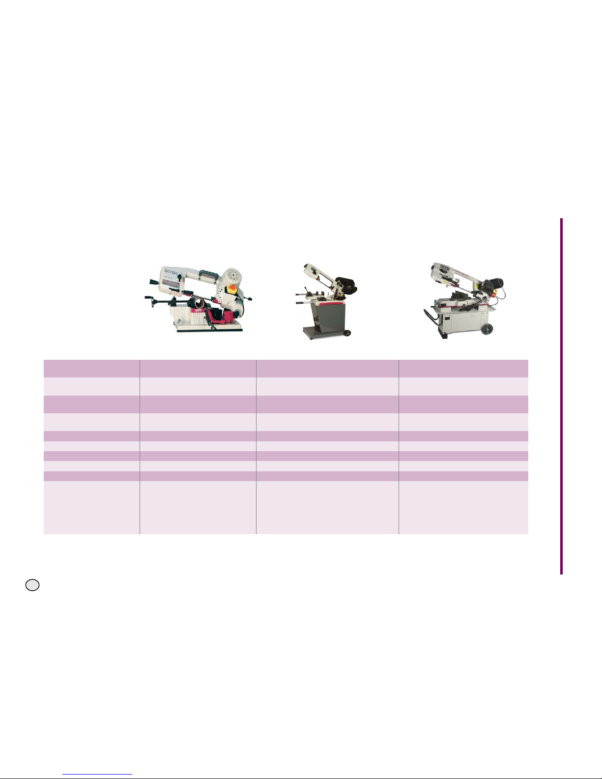
OPTIMUM
MASCHINEN - GERMANY
© 2008
GB
The metal belt saws at a glance
Optimum metal belt saws
Model S 100 G S 130 GH S 181 G
Cutting range 90°
Round bars
100 mm 128 mm 180 mm
Cutting range 90°
Rectangular bars
100x150 mm 100x150 mm 180x240 mm / 65 x 300 mm
Cutting range 45°
Round bars
65 mm 56 mm 110 mm
Cutting range 45°
Rectangular bars
100x60 mm 56x56 mm 170x110 mm
Dimensions of the saw belt 1,470 x 13 x 0.65 mm 1,638 x 13 x 0.65 mm 2,362 x 19 x 0.9 mm
Speeds 45 m/min. 22 / 31 / 55 m/min. 39 / 66 / 82 m/min.
Dimensions 724 x 381 x 458 mm 980 x 385 x 1060 mm 1,275 x 450 x 1,100 mm
Power rating 370W / 230 V / 50 Hz 0.25 kW/ 230 V / 50 Hz 0.73 kW / 400 V / 50 Hz
Item no.: 330 0100 330 0130 330 0182
Components delivered
Automatic end disconnection
Quick acting screw vice
Bimetallic saw blade
Depth stop
Automatic end disconnection
Depth stop
Quick acting screw vice
Substructure
Bimetallic saw blade
Depth stop
Automatic end disconnection
Bimetallic saw blade
Depth stop
Liquid cooling system
Page 67
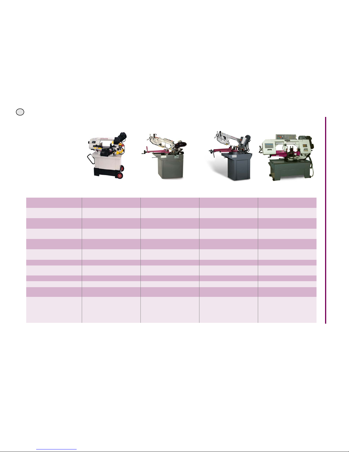
OPTIMUM
MASCHINEN - GERMANY
© 2008
GB
Optimum metal belt saws
Model S 181 GG S 210 G
(Vario)
S 275 G
(Vario)
S 300 VG
Cutting range 90°
Round bars
180 mm 170 mm 225 mm 254mm
Cutting range 90°
Rectangular bars
180x220 mm / 50 x 260 mm 140x200 mm 245x180 mm / 65 x 300 mm 76 x 458mm / 254 x 254 mm
Cutting range 45°
Round bars
105 mm 100 mm 160 mm 254mm
Cutting range 45°
Rectangular bars
120x105 mm 100x140 mm 160x160 mm 254 x 280mm
Cutting range 60°
Round bars
- - - 204
Cutting range 60°
Rectangular bars
- - - 127 x 204mm / 178 x 178mm
Dimensions of the saw belt 2,362 x 19 x 0.9 mm 2,080 x 20 x 0.9 mm 2,480 x 27 x 0.9 mm 3352 x 27 x 0.9 mm
Speeds 39 / 66 / 82 m/min.
40 / 80 m/min.
(12 - 120 m/min)
45 / 90 m/min.
(14 - 120 m/min)
25 - 100 m/min
Dimensions 1,275 x 570 x 1,140 mm 1,300 x 580 x 780 mm 1,380 x 580 x 930 mm 1840 x 700 x 1080
Power rating 0.73 kW / 400 V / 50 Hz 0.75 kW/ 230 V / 50 Hz 1.1 kW / 400 V / 50 Hz 1.5 kW / 400 V / 50 Hz
Item no.: 330 0183
330 0210
(3012210)
330 0275
(3012275)
3290300
Components delivered
Liquid cooling system
Bimetallic saw blade
Depth stop
Hydraulic lowering cylinder
Saw belt
Liquid cooling system
Substructure
Depth stop
Automatic end disconnection
Bimetallic saw blade
Depth stop
Liquid cooling system
Automatic end disconnection
Bimetallic saw blade
Depth stop
Liquid cooling system
Page 68

OPTIMUM
MASCHINEN - GERMANY
© 2008
GB
quantum metal belt saws
Model S 91 G S 121 G S 181
Cutting range 90°
Round bars
90 mm 115 mm 178 mm
Cutting range 90°
Rectangular bars
90x130 mm 100x150 mm 178x240 mm / 50 x 300 mm
Cutting range 45°
Round bars
65 mm 100 mm 110 mm
Cutting range 45°
Rectangular bars
65x50 mm 85x65 mm 170x110 mm
Dimensions of the saw belt 1,300 x 12.7 x 0.5 mm 1,638 x 13 x 0.65 mm 2,362 x 19 x 0.9 mm
Speeds 20 / 29 / 50 m/min. 21 / 31 / 54 m/min. 21 / 33,5 / 45 / 50 m/min.
Dimensions 710 x 260 x 410 mm 1,020 x 410 x 400 mm 1,295 x 450 x 1,060 mm
Power rating 250W / 230 V / 50 Hz 370 W/ 230 V / 50 Hz 750 W / 400 V / 50 Hz
Item no.: 330 0091 330 0121 330 0181
Components delivered
Quick acting screw vice
Bimetallic saw blade
Automatic end disconnection
Quick acting screw vice
Bimetallic saw blade
Automatic end disconnection
Bimetallic saw blade
Liquid cooling system
Depth stop
 Loading...