

Page 1
OPTIMUM
M A S C H I N E N - G E R M A N Y
? 2010
US
Page 1llirD lliMoiraV 03 FB6.0.1 noisreV0102 / 80 / 72
Operating manual
Version 1.0.6
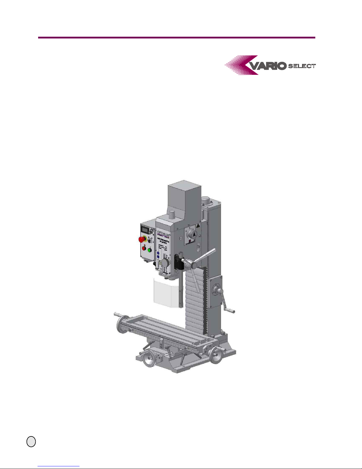
Mill Drill
BF 30 Vario
Item No. 3338438
Optional Stand Item No. 3353004
Keep for future reference!
Page 2

OPTIMUM
MASCHINEN - GERMANY
© 2010
US
Page 2 Mill Drill BF 30 Vario Version 1.0.6 27 / 08 / 2010
Table of Contents
Preface
Changes The illustrations of the mill drill might in some details deviate from the illustrations of this operating
manual but this will have no influence on the operation of the mill drill.
Any changes in the construction, equipment and accessories are reserved for reasons of
enhancement. Therefore, no claims may be derived from the instructions and descriptions.
1 Safety
1.1 Safety warnings (warning notes).............................................................................................5
1.1.1 Classification of hazards..............................................................................................5
1.1.2 Other pictograms.......................................... ... ................................................ ... ......... 6
1.2 Proper use ..............................................................................................................................7
1.3 Possible dangers caused by the mill drill................................................................................7
1.4 Qualification of personnel........................................................................................................8
1.4.1 Target group................................................................................................................8
1.5 Safety measures during operation.................................... ... ................................................... 8
1.6 Safety devices.........................................................................................................................9
1.6.1 EMERGENCY-STOP button........................................................................................ 9
1.6.2 Lockable main switch.................................... ... ... ................................................ ... .... 10
1.6.3 Protective cover.........................................................................................................10
1.6.4 Separating protective equipment....................................................... ........................ 11
1.7 Safety check ......................................................................................................................... 11
1.8 Individual protection gear...................................................................................................... 12
1.9 For your own safety during operation.................................................................................... 12
1.10 Disconnecting the mill drill and making it safe ......................................................................13
1.11 Using lifting equipment.......................................................................................................... 13
2 Technical data
2.1 Power Supply........................................................................................................................ 14
2.2 Milling-drilling capacity.......................................................................................................... 14
2.3 Spindle holding fixture........................................................................................................... 14
2.4 Mill drill head.........................................................................................................................14
2.5 Cross table............................................................................................................................14
2.6 Work area.............................................................................................................................. 14
2.7 Speeds..................................................................................................................................14
2.10 Emissions..............................................................................................................................15
2.8 Environmental conditions......................................................................................................15
2.9 Operating material.................................................................................................................15
2.11 Installation plan............................ .........................................................................................16
2.12 Installation plan of optional stand..........................................................................................17
3 Unpacking and connecting
3.1 Extent of supply .................................................................................................................... 18
3.2 Transport...............................................................................................................................18
3.3 Storage ................................................................................................................................. 19
3.4 Installation and assembly...................................................................................................... 20
3.4.1 Site requirements....................................................................................................... 20
3.4.2 Load suspension point...............................................................................................20
3.4.3 Installation..................................................................................................................20
3.5 First use................................................................................................................................21
3.5.1 Power supply........................................................................................... .................. 21
3.5.2 Cleaning and lubricating............................................................................................ 21
3.5.3 Fill in gear lubricant oil...............................................................................................22
3.6 Optional accessories........................................... .................................................................. 22
4 Operation
4.1 Safety....................................................................................................................................23
4.2 Control and indicating elements............................................................................................23
4.2.1 Control panel ............................................................................................................. 24
4.3 Starting the mill drill............................................................................................................... 25
Page 3

OPTIMUM
MASCHINEN - GERMANY
© 2010
US
Page 327 / 08 / 2010 Version 1.0.6 BF 30 Vario Mill Drill
4.4 Switching off the mill drill.......................................................................................................25
4.5 Inserting a tool.......................................................................................................................25
4.5.1 Installation..................................................................................................................25
4.5.2 Disassembly...............................................................................................................26
4.5.3 Use of collet chucks...................................................................................................26
4.6 Clamping the workpieces......................................................................................................26
4.7 Changing the speed range................................. ... ................................................................27
4.8 Selecting the speed.................................................................................................... ... ........27
4.8.1 Standards values for cutting speeds..........................................................................27
4.8.2 Standard values for speeds with HSS – Eco – twist drilling (U.S. unit.......................29
4.9 Manual spindle feed with the fine feed..................................................................................30
4.10 Manual spindle feed with the spindle quill lever ....................................................................30
4.11 Digital display for spindle travel.............................................................................................30
4.11.1 Technical data............................................................................................................30
4.11.2 Design........................................................................................................................30
4.12 Troubleshooting.....................................................................................................................31
4.13 Swivelling the mill drill head ..................................................................................................31
5 Maintenance
5.1 Safety....................................................................................................................................32
5.1.1 Preparation ................................................................................................................32
5.1.2 Restarting...................................................................................................................33
5.2 Inspection and maintenance .................................................................................................33
5.3 Repair....................................................................................................................................38
6 Spare parts - BF30 Vario
6.1 Column..................................................................................................................................39
6.2 Cross table 1 of 2..................................................................................................................40
6.3 Cross table 2 of 2..................................................................................................................41
6.4 Protection device...................................................................................................................42
6.5 Milling head 1 of 3 .................................................................................................................43
6.6 Milling head 2 of 3 .................................................................................................................44
6.7 Milling head 3 of 3 .................................................................................................................45
6.8 Machine stand (optional).......................................................................................................46
6.9 Parts list.................................................................................................................................47
6.10 Wiring diagram 1 of 2.................................................. .. ................................................ ........52
6.11 Wiring diagram 2 of 2.................................................. .. ................................................ ........53
7 Troubleshooting
7.1 Troubleshooting the mill drill...................................................... ............................................54
8 Appendix
8.1 Copyright...............................................................................................................................55
8.2 Terminology/Glossary ...........................................................................................................55
8.3 LIMITED WARRANTY ..........................................................................................................56
9 Index
Page 4

Safety
OPTIMUM
MASCHINEN - GERMANY
© 2010
US
Page 4 Mill Drill BF 30 Vario Version 1.0.6 27 / 08 / 2010
1 Safety
Glossary of symbols
This part of the operating manual
explains the meaning and use of the warning references contained in the operating
manual,
explains how to use the mill drill properly,
highlights the dangers that might arise for you and others if these instructions are not
obeyed.
In addition to this operating manual please observe
applicable laws and regulations,
legal regulations for accident prevention,
the prohibition, warning and mandatory signs as well as the warning notes on the mill drill.
ALWAYS KEEP THIS DOCUMENTATION CLOSE TO THE MILL DRILL.
INFORMATION
If you are unable to solve a problem using this manual, please contact us for advice:
Exclusive USA Agent
Colovos Company
4444 West Ohio Street
Chicago, IL 60624
Tel.: (773) 533-4216
give additional indications
calls on you to act
enumerations
Page 5
OPTIMUM
MASCHINEN - GERMANY
Safety
© 2010
US
Page 527 / 08 / 2010 Version 1.0.6 BF 30 Vario Mill Drill
1.1 Safety warnings (warning notes)
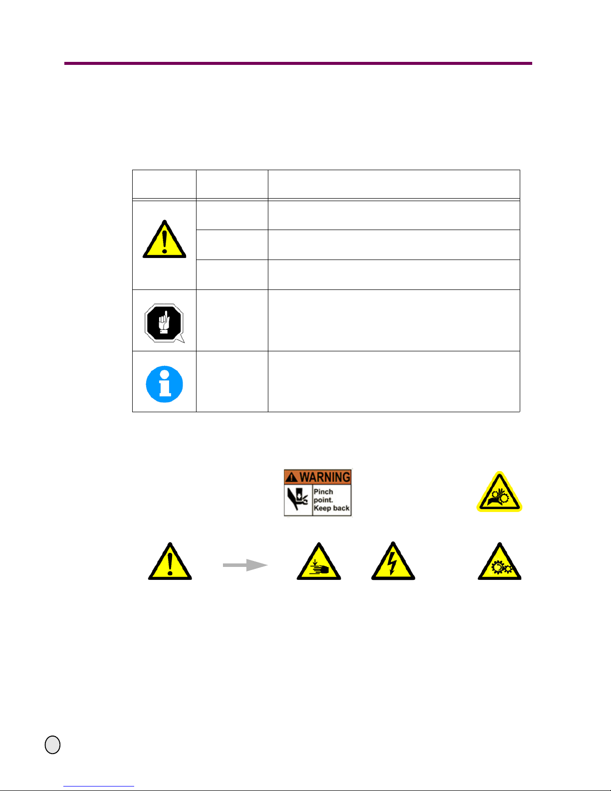
1.1.1 Classification of hazards
We classify the safety warnings into various levels. The table below gives an overview of the
classification of symbols (pictograms) and warnings for the specific danger and its (possible)
consequences.
Pictogram
Alarm
Expression
Definition/Consequences
DANGER!
Imminent danger that will cause serious injury or death to
personnel.
WARNING!
Risk: a danger that might cause serious injury or death to
personnel.
CAUTION!
Danger of unsafe procedure that might cause injury to
personnel or damage to property.
ATTENTION!
Situation that could cause damage to the mill drill and
product and other types of damage.
No risk of injury to personnel.
INFORMATION
Application tips and other importan t or useful information
and notes.
No dangerous or harmful consequences for personnel or
objects.
In the case of specific dangers, we replace the pictogram
or
General
danger
with a warning ofinjuries to
hands,
hazardous
electrical
voltage
,
rotating parts.
Page 6

Safety
OPTIMUM
MASCHINEN - GERMANY
© 2010
US
Page 6 Mill Drill BF 30 Vario Version 1.0.6 27 / 08 / 2010
1.1.2 Other pictograms
Warning of
automatic start-up!
Disconnect main power!
Activation forbidden!
Use ear protection!
Use protective
boots!
Use protective gloves!
Wear a safety suit! Protect the environment!
Use protective goggles!
Contact address
Page 7

OPTIMUM
MASCHINEN - GERMANY
Safety
© 2010
US
Page 727 / 08 / 2010 Version 1.0.6 BF 30 Vario Mill Drill
1.2 Proper use
WARNING!
In the event of improper use, the mill drill
• will endanger personnel,
• will endanger the mill drill and other material property of the operator,
• may affect proper operation of the mill drill.
The mill drill is designed and manufactured to be used for milling and drilling cold metals or
other non-flammable materials or that do not constitute a health hazard by using commercial
milling and drilling tools.
The mill drill must only be installed and operated in a dry and well-ventilated place.
If the mill drill is used in any way other than described above, or modified without authorization,
then the mill drill- is being used improperly.
We do not take liability for damages caused by improper use.
We would like to stress that any modifications to the construction, or technical or technological
modifications that have not been authorized will also render the warranty null and void.
the maximum values for the mill drill are complied with,
the operating manual is observed,
inspection and maintenance instructions are observed.
„Technical data“ on page 14
WARNING!
Very serious injury due to improper use.
It is forbidden to make any modifications or alterations to the operating values of the mill
drill. These could endanger the staff and cause damage to the mill drill.
1.3 Possible dangers caused by the mill drill
The mill drill was built using the latest technological advances.
Nonetheless there remains a residual risk, since the mill drill operates with
high revolutions,
rotating parts and tools,
electrical voltage and currents.
We have used construction resources and safety techniques to minimise the health risk to the
staff resulting from these hazards.
If the mill drill is used and maintained by personnel who are not duly qualified, there may be a
risk by the mill drill resulting from incorrect operation or unsuitable maintenance.
All personnel involved in assembly, commissioning, operation and maintenance must
be duly qualified,
strictly follow this operating manual .
Disconnect the mill drill from the electrical power whenever cleaning or maintenance work is
being carried out.
Page 8

Safety
OPTIMUM
MASCHINEN - GERMANY
© 2010
US
Page 8 Mill Drill BF 30 Vario Version 1.0.6 27 / 08 / 2010
WARNING!
The mill drill may only be used with the safety devices activated.
Disconnect the mill drill from the electrical power whenever you detect a failure in the
safety devices or when they are not fitted!
All additional installations carried out by the operator need to incorporate the prescribed
safety devices.
As the machine operator, this will be your responsibility!
„Safety measures during operation“ on page 8
1.4 Qualification of personnel
1.4.1 Target group
This manual is addressed to
the operator,
the user,
the maintenance staff.
The warning notes therefore refer to both operation and maintenance of the mill drill.
Always disconnect the mill drill plug from the electrical power. This will prevent it being used by
unauthorised staff.
INFORMATION
All personnel involved in assembly, commissioning, operation and maintenance need to
be duly qualified,
strictly follow this operating manual .
In the event of improper use
there may be a risk to the staff,
there may be a risk to the mill drill and other material property,
may affect proper operation of the mill drill.
1.5 Safety measures during operation
CAUTION!
Risk due to inhaling health hazardous dusts and mist.
Depending on the material being processed and any additional dusts and mist in the
work area, conditions might impair your health.
Make sure that the generated health hazardous dusts and mist are safely removed at the
point of origin and are collected and/ or filtered from the working area. Use an appropriate dust collection/ filter unit.
CAUTION!
Risk of fire and explosion by using flammable materials or cooling lubricants.
Take additional preventive measures in order to safely avoid health hazards before processing flammable materials (e.g. aluminum, magnesium) or before using flammable
additives (e.g. solvents).
Page 9
OPTIMUM
MASCHINEN - GERMANY
Safety
© 2010
US
Page 927 / 08 / 2010 Version 1.0.6 BF 30 Vario Mill Drill
1.6 Safety devices
Use the mill drill only with properly functioning safety devices.
Stop the mill drill immediately if there is a failure in the safety device or if it is not functioning for
any reason.
It is your responsibility!
If a safety device has been activated or has failed, the mill drill must only be used when
the cause of the failure has been removed,
it has been verified that there is no resulting danger for the staff or objects.
WARNING!
If you bypass, remove or override a safety device in any other way, you are endangering
yourself and other personnel working with the mill drill. The possible consequences are
• damage as a result of components or parts of components flying off at high speed,
• contact with rotating part s,
• fatal electrocution.
The mill drill includes the following safety devices:
an EMERGENY-STOP button,
a protective cover at the drill-mill head,
a separating protective equipment on the milling spindle.
WARNING!
The separating protective eq uipment wh ic h is ma de a vailab le and delive red tog ether with
the machine is designed to reduce the risk of workpieces or fractions of them from being
expelled, but not to remove them completely.
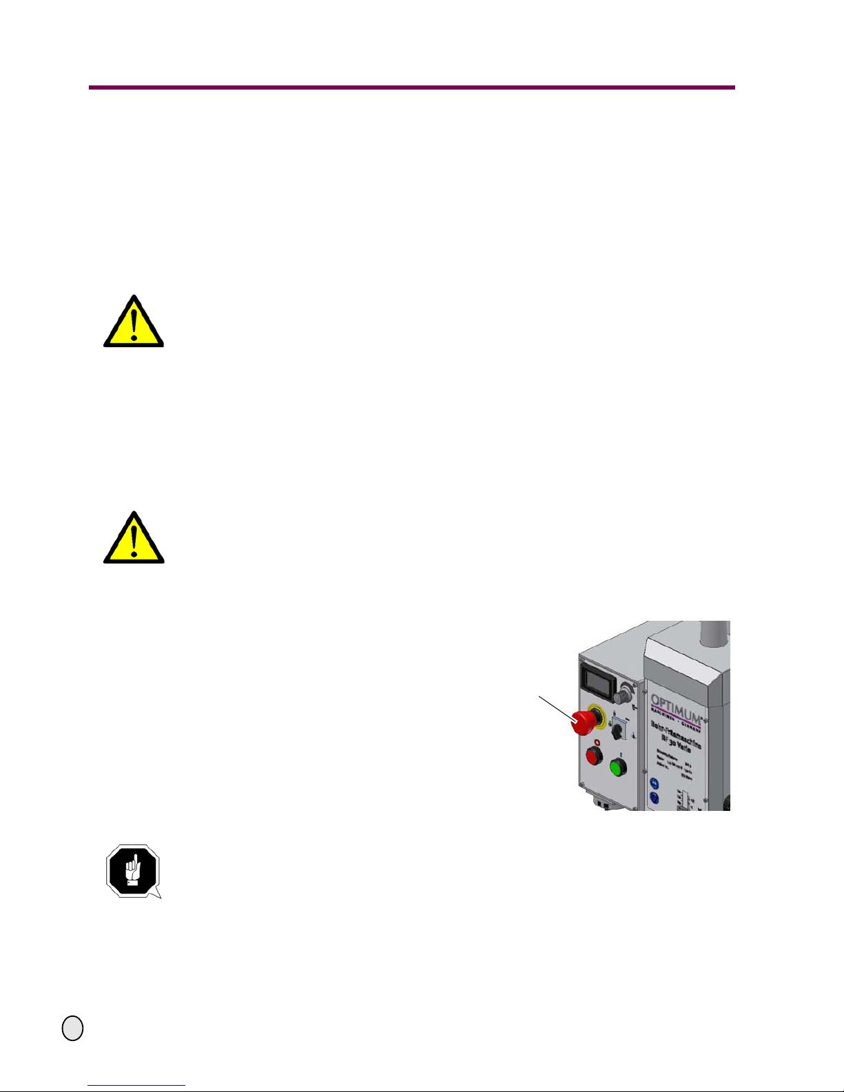
1.6.1 EMERGENCY-STOP button
The EMERGENCY-STOP button switches
the mill drill off.
„Starting the mill drill“ on page 25
Fig. 1-1: EMERGENCY-STOP button
ATTENTION!
The EMERGENCY-STOP button switches off the mill drill immediately.
Only press the EMERGENCY-STOP button in case of danger! If the emergency stop button is actuated in order to stop the mill drill generally you might damage tools or
workpieces.
After actuating the button, turn it to the right, in order to restart the machine.
EMERGENCY-STOP
Page 10
Safety
OPTIMUM
MASCHINEN - GERMANY
© 2010
US
Page 10 Mill Drill BF 30 Vario Version 1.0.6 27 / 08 / 2010
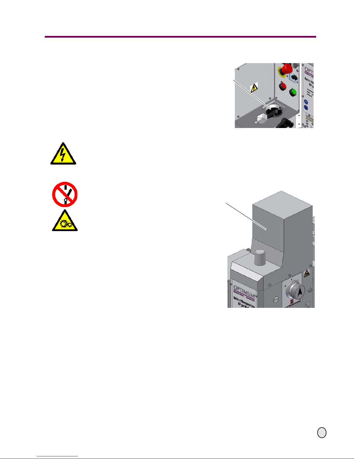
1.6.2 Lockable main switch
In the position " 0 " the lockable main
switch can be secured against accidental
or non-authorised switching on by means
of a padlock.
When the main switch is switched off, the
current supply is interrupted, except for
areas marked by the pictogram below.
Fig. 1-2: Main switch
WARNING!
Dangerous voltage even if the main switch is switched off. In areas marked by this picto-
gram, there might be voltage, even if the main switch is switched off.
1.6.3 Protective cover
The drill-mill head is fitted with a protective
cover.
WARNING!
Remove the protective cover only after
the power plug of the mill drill has been
pulled out of the receptacle.
Fig. 1-3: Protective cover
Main switch
Protective cover
Page 11
OPTIMUM
MASCHINEN - GERMANY
Safety
© 2010
US
Page 1127 / 08 / 2010 Version 1.0.6 BF 30 Vario Mill Drill
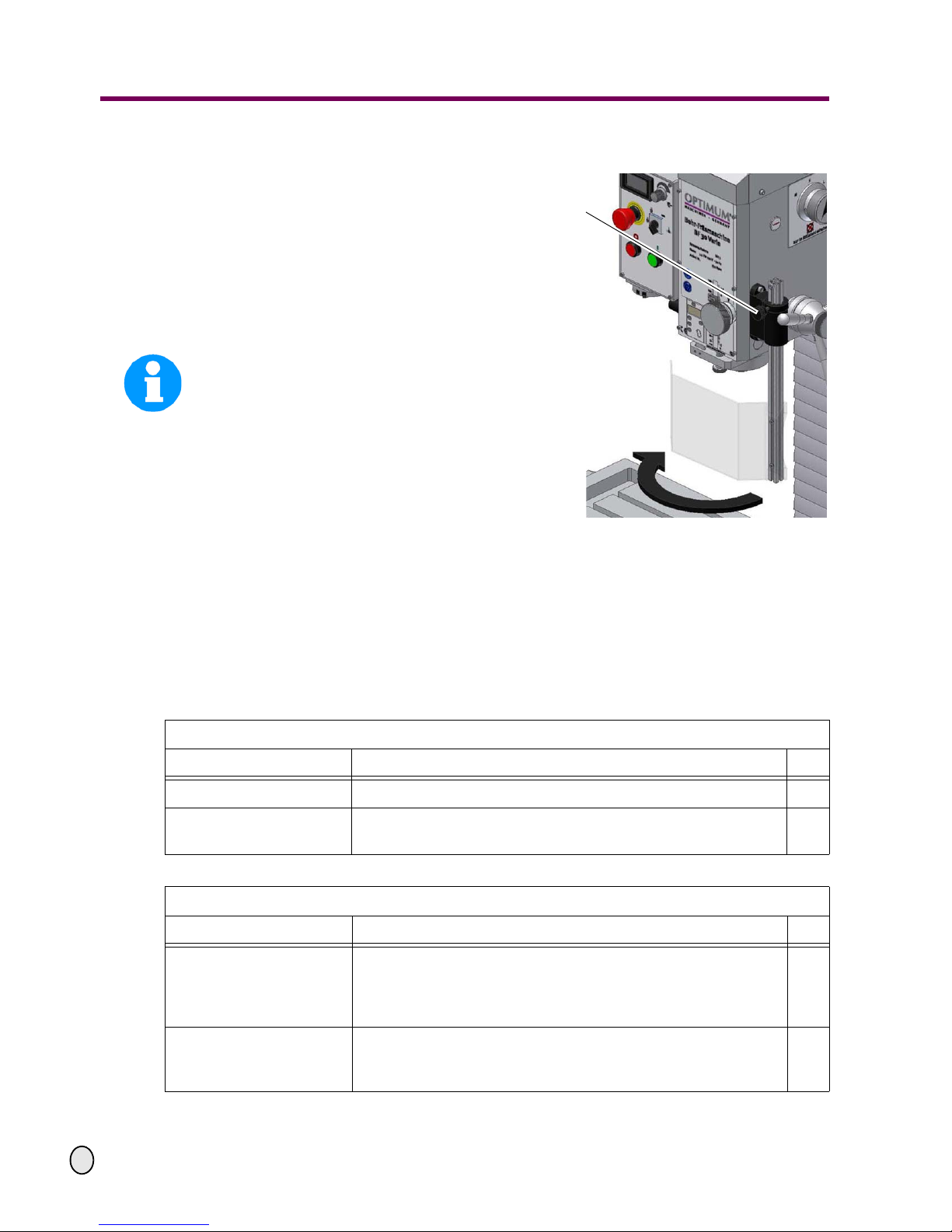
1.6.4 Separating protective equipment
Adjust the protective guard equipment to
the correct height before you start working.
To do so, detach the clamping screw,
adjust the required height and retighten
the clamping screw.
A switch is integrated in the fixture of the
spindle protection which monitors that the
cover is closed.
INFORMATION
YOU CANNOT START THE MACHINE IF
THE PROTECTIVE GUARD IS NOT
CLOSED.
Fig. 1-4: Separating protective equipment
1.7 Safety check
Check the mill drill regularly.
Check all safety advices
at the beginning of each shift,
once a week (with the machine in operation),
after every maintenance and repair operation.
Locking screw
General check
Equipment Check OK
Protective covers
Fitted, firmly bolted and not damaged
Labels,
markings
Installed and legible
Run test
Equipment Check OK
EMERGENCY-STOP button
When the EMERGENCY-STOP button is activated, the mill drill
should switch off. A restart will not be possible until the EMERGENCY-STOP button has been unlocked and the ON switch has
been activated.
Separating protective
equipment around the
drilling and milling spindle
Only switch on the mill drill if the protective equipment is closed.
Page 12

Safety
OPTIMUM
MASCHINEN - GERMANY
© 2010
US
Page 12 Mill Drill BF 30 Vario Version 1.0.6 27 / 08 / 2010
1.8 Individual protection gear
For certain work individual protection gear is required.
Protect your face and eyes: During all work and specifically work during which your face and
eyes are exposed to hazards, a safety helmet with a face guard should be worn.
Use protective gloves when handling pieces with sharp edges.
Use safety shoes when you position, dismantle or transport heavy components.
Use ear protection if the noise level (emission) in the workplace exceeds 80 dB (A).
Before starting work, make sure that the prescribed individual protection gear is available at the
workplace.
CAUTION!
Dirty or contaminated body protection gear can cause disease. Clean it each time after it
has been used and once a week.
1.9 For your own safety during operation
WARNING!
Before activating the mill drill, double check that this will not endanger other people and
cause damage to equipment.
Avoid any unsafe working practises:
Make sure your work does not endanger anyone.
The instructions in this manual need to be observed during assembly, handling, main-
tenance and repair.
Use protective goggles.
Turn off the mill drill before measuring the workpiece.
Do not work on the mill drill if your concentration is reduced, for example, because you are
taking medication.
Stay on the mill drill until the working spindle has come to a complete halt.
Use prescribed protection gear. Make sure to wear a well-fitting work suit, when
necessary, a hairnet.
Do not use protective gloves during drilling or milling work.
Unplug the shockproof plug from the electrical power before changing the tool.
Use suitable devices for removing drilling and milling chips.
Make sure your work does not endanger anyone.
Clamp the workpiece tightly before activating the mill drill.
In the description of work with and on the mill drill we highlight the dangers specific to that work.
Page 13

OPTIMUM
MASCHINEN - GERMANY
Safety
© 2010
US
Page 1327 / 08 / 2010 Version 1.0.6 BF 30 Vario Mill Drill
1.10 Disconnecting the mill drill and making it safe
Unplug the machine from the electrical power before beginning any maintenance or repair work.
1.11 Using lifting equipment
WARNING!
Use of unstable lifting equipment and load-suspension devices that brea k unde r load c an
cause very serious injury or even death.
Check that the lifting equipment and load-suspension devices are of sufficient load
capacity and are in perfect condition.
Observe the rules for preventing accidents issued by OSHA or other inspection authori-
ties.
Hold the loads properly.
Never walk under suspended loads!
Positions of the signs on the mill drill
Fig. 1-5: BF 30 Vario
Page 14

Technical data
OPTIMUM
MASCHINEN - GERMANY
27 / 08 / 2010Page 14 Technical data Mill Drill BF 30 Vario ; Version 1.0.6
© 2010
US
2 Technical data
The following information gives the dimensions and weight and is the manufacturer’s authorised
machine data.
2.1 Power Supply
Motor 3 HP, 230V, 1Ph, 60Hz
2.2 Milling-drilling capacity
Drilling capacity in steel 24 mm /0.9" max. diam.
Drilling capacity cast iron 28 mm /1.1" max. diam.
Milling capacity of end-mill cutter 30 mm /1.2" max. diam.
Milling capacity of inserted tooth cutter 75 mm /2.9" max. diam.
Swing 440 mm /17.3"
2.3 Spindle holding fixture
Spindle holding fixture R8
Extraction rod (Draw bar) M12
Qill travel 90 mm /3.5"
2.4 Mill drill head
Swivelling + / - 90°
Gearbox stages 3
Z-axis travel 470 mm /18.5"
2.5 Cross table
Table length 750 mm /29.5"
Table width 210 mm /8.3"
Y-axis travel 200 mm/7.9"
X-axis travel 450 mm /17.7"
T-slots 1/2" slots, three
2.6 Work area
Height 2100 mm /82.7"
Depth 1900 mm /74.8"
Width 2500 mm /98.4"
Total Weight 265 Kg. /584 lbs
2.7 Speeds
Gearbox stage low 80 - 1100 RPM
Gearbox stage middle 160 - 1700 RPM
Gearbox stage rapid 320 - 3100 RPM
Page 15
OPTIMUM
MASCHINEN - GERMANY
Technical data
27 / 08 / 2010 Page 15Technical data Mill Drill BF 30 Vario ; Version 1.0.6
© 2010
US
2.10 Emissions
The noise level (emission) of the mill drill is below 76 dB(A). If the mill drill is installed in an area
where various machines are in operation, the acoustic influence on the operator of the mill drill
may exceed 85 dB(A).
INFORMATION
This numeric value had been measured on a new machine under conventional operating conditions. Depending on the age or wear of the machine, the noise behavior of the machine might
change.
Furthermore, the extent of the noise emission is also depending on manufacturing
influence factors, such as speed, material and clamping conditions.
INFORMATION
The mentioned numerical value is an emission level and not necessarily a safe
working level.
Unless the degree of noise emission and the degree of noise disturbance are depending on one
another it is not possible to use it in order to reliably determine if it is necessary to take further
preventive measures or not.
The following factors influence the actual degree of the noise disturbance of the
operator:
• Characteristics of the working chamber, e.g. size or damping behavior,
• Other noise sources, e.g. the number of machines,
• Other processes proceeding nearby and the period during which the operator is exposed to
the noise.
Consult OSHA, state and local regulations in orde r to determine complianc e, dangers and risks
to the operator.
CAUTION!
The machine operator has to wear an appropriate ear protection depending on the overall
stress caused by noise and on the basic limit values.
We generally recommend using a sound and ear protection.
2.8 Environmental conditions
Temperature 40 - 95 °F (5 - 35 °C)
Humidity 25 - 80%
2.9 Operating material
BF 30 Vario
Gearbox Oil quantity 1-1/4 Qts. (1.2 L)
628 Mobil (Vis. 100/150)
Blank steel parts Mobilux EP 004, acid-free oil, e.g., motor oil
Page 16

Technical data
OPTIMUM
MASCHINEN - GERMANY
27 / 08 / 2010Page 16 Technical data Mill Drill BF 30 Vario ; Version 1.0.6
© 2010
US
2.11 Installation plan
Fig. 2-1: Installation plan
Page 17
OPTIMUM
MASCHINEN - GERMANY
Technical data
27 / 08 / 2010 Page 17Technical data Mill Drill BF 30 Vario ; Version 1.0.6
© 2010
US
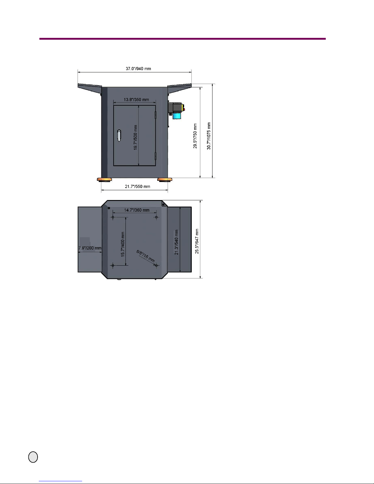
2.12 Installation plan of optional stand
Fig. 2-2: Installation plan of optional stand
Page 18
Unpacking and connecting
OPTIMUM
MASCHINEN - GERMANY
© 2010
US
Page 18 Mill Drill BF 30 Vario Version 1.0.6 Stand 27 / 08 / 2010
3 Unpacking and connecting
INFORMATION
The mill drill comes pre-assembled.
3.1 Extent of supply
When the mill drill is delivered, immediately check that the machine has not been damaged
during shipping and that all components are included. Also check that no fastening screws have
come loose.
Compare the parts supplied with the information on the packaging list.
3.2 Transport
WARNING!
Machine parts falling off forklift trucks or other transport vehicles could cause very
serious or even fatal injuries. Follow the instructions and information on the transport
case.
WARNING!
Use of unstable lifting equipment and load-suspension devices that break u nder load ca n
cause very serious injury or even death.
Check that the lifting and load-suspension gear has sufficient load capacity and that it is
in perfect condition. Observe the rules for preventing accidents issued by OSHA or other
inspection authorities.
Hold the loads properly. Never walk under suspended loads!
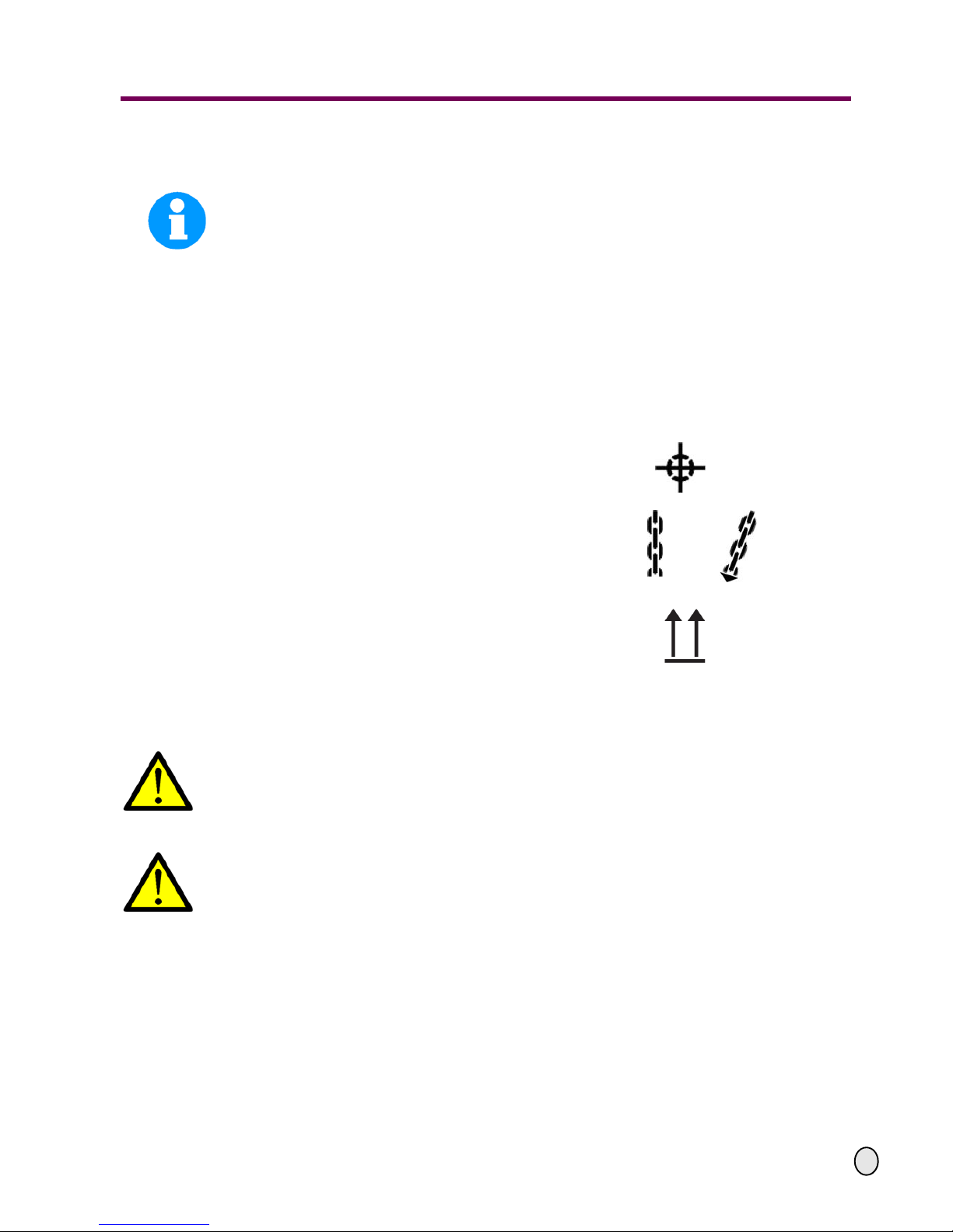
Center of gravity
Attachment positions (marking the positions for
the attachment position gear)
Prescribed transport position (marking the top
side)
Means of transportation to be used
Weights
Page 19

OPTIMUM
MASCHINEN - GERMANY
Unpacking and connecting
© 2010
US
Page 19Stand 27 / 08 / 2010 Version 1.0.6 BF 30 Vario Mill Drill
3.3 Storage
ATTENTION!
Improper storage may cause important parts to be damaged or destroyed.
Store packed or unpacked parts only under the following ambient conditions.
Please follow the instructions and indications on the transportation box.
Fragile goods (goods require careful handling)
Protect against humidity and humid envir on m en ts
„Environmental conditions“ on page 15.
Prescribed position of the packaging box (marking
the top side – arrows pointing upward)
Maximum stacking height
Example: non-stackable – do not pile any further
packaging boxes on top of the first packaging box
Page 20

Unpacking and connecting
OPTIMUM
MASCHINEN - GERMANY
© 2010
US
Page 20 Mill Drill BF 30 Vario Version 1.0.6 Stand 27 / 08 / 2010
3.4 Installation and assembly
3.4.1 Site requirements
Organize the working space around the mill drill according to the local safety regulations.
INFORMATION
In order to provide for good functionality and high machining accuracy as well as long durability
of the machine the site should fulfill certain criteria.
Observe the following items:
The device must only be installed and operated in dry ventilated places.
Avoid places nearby machines generating chips or dust.
The site has to be vibration-free, i.e. at a distance from presses, planing machines, etc.
The substructure has to be appropriate for mill drill. Also make sure that the load bearing
capacity and the evenness of the floor are appropriate.
The substructure has to be prepared in a way that possibly used coolant cannot penetrate
into the ground.
Protruding parts such as stops, handles, etc. need to be secured by measures provided by
the customer if necessary in order to avoid dangers for persons.
Provide sufficient space for assembly and operating staff as well as for material transport.
Also allow for accessibility for setting and maintenance works.
Make sure that the mains plug of the turning machine is freely accessible.
Provide for sufficient illumination (minimum value: 47 Lumens/ft², measured at the tool tip). In
case of insufficient intensity of illumination provide for additional illumination i.e. by a separate workplace illuminator.
INFORMATION
The mains plug of the mill drill has to be freely accessible.
3.4.2 Load suspension point
WARNING!
Danger of crushing and overturning. Proceed with extreme caution when lifting, installing and
assembling the machine.
Secure the load-suspension device around the drill-mill head. Use a lifting sling for this pur-
pose.
Clamp all the clamping levers at the mill drill before lifting the mill drill.
Make sure that no add-on pieces or varnished parts are damaged due to the load-suspen-
sion.
3.4.3 Installation
Check the horizontal orientation of the base of the mill drill with a spirit level.
Check that the foundation has sufficient floor-load capacity and rigidity. The total weight of
the mill drill is 584 lbs./265 Kg.
Page 21

OPTIMUM
MASCHINEN - GERMANY
Unpacking and connecting
© 2010
US
Page 21Stand 27 / 08 / 2010 Version 1.0.6 BF 30 Vario Mill Drill
ATTENTION!
Insufficient rigidity of the foundation leads to the superpos itio n of vibra tions betwe en the
mill drill and the foundation (natural frequency of components). Insufficient rigidity of the
entire milling machine assembly also rapidly causes the machine to reach critical
speeds, with unpleasant vibrations, leading to bad milling results.
Position the mill drill on the intended foundation.
Attach the mill drill using the provided recesses in the machine base.
WARNING!
The quality of the stand and the kind of fixture of the machine stand to the substructure
has to assimilate the loads of the machine. The substructure needs to be even. Please
check the horizontal alignment of the substructure of the machine with a level. Fix the
machine to the substructure at the provided recesses at the stand. Connector cartridges
or heavy-duty bolts are strongly recommended.
„Installation plan“ on page 16,
„Installation plan of optional stand“ on page 17.
3.5 First use
WARNING!
Risk by using improper workpiece clamping materials or by operating the machine with
inadmissible speed.
Only use the clamping materials (e.g. drill chuck) which had been delivered together with
the machine or as optional equipment.
Use the working clamping materials only in the provided admissible speed range.
Workpiece clamping materials must only be modified according to the recommendations
or of the clamping material manufacturer.
WARNING!
Staff and equipment may be endanged if the mill drill is first used by inexperienced staff.
We do not take responsibility for damage caused by incorrect commissioning.
„Qualification of personnel“ on page 8
3.5.1 Power supply
Connect the electrical supply cable.
Check the fuse protection (fuse) of your electrical supply according to the technical specifica-
tions for the total connected load of the mill drill.
3.5.2 Cleaning and lubricating
Remove the anti-corrosive agent applied to the mill drill for transport and storage purposes.
We recommend the use of mineral spirits with a soft cloth.
Do not use any solvents, thinners or other cleaning agents which could corrode the varnish
on the mill drill. Follow the specifications and indications of the manufacturer of the cleaning
agent.
Lubricate all bright machine parts with non-corrosive lubricating oil.
Grease the mill drill using the lubrication chart.
„Inspection and maintenance“ on page 33
Page 22

Unpacking and connecting
OPTIMUM
MASCHINEN - GERMANY
© 2010
US
Page 22 Mill Drill BF 30 Vario Version 1.0.6 Stand 27 / 08 / 2010
Check the smooth running of all spindles. The spindle nuts can be readjusted.
Disassemble the taper gibs of the cross table and clean the gibs from the anti-corrosive
agent.
„Taper gib“ on page 37
3.5.3 Fill in gear lubricant oil
The mill drill is delivered without oil. Fill in gear lubricant oil.
„Oil change“ on page 34
3.6 Optional accessories
Designation: Item No
Machine stand
Dimensions (L x W x H): 25.5 x 21.7 x 29.5"
650 x 550 x 750 mm
3353004
Vice 5" Precision Modular 3355553
Page 23

OPTIMUM
MASCHINEN - GERMANY
Operation
© 2010
US
Page 23Stand 27 / 08 / 2010 Version 1.0.6 BF 30 Vario Mill Drill
4 Operation
4.1 Safety
Use the mill drill only under the following conditions:
The mill drill is in proper working order.
The mill drill is used as prescribed.
The operating manual is followed.
All safety devices are installed and activated.
All problems should be eliminated immediately. Stop the mill drill immediately in the event of any
problem in operation and make sure it cannot be st ar te d-up acciden tally or without authorisation.
„For your own safety during operation“ on page 12
4.2 Control and indicating elements
Fig. 4-1: BF 30 Vario
Selector switch for gearbox stage
Right clamping screw of
mill drill head
Star grip for spindle sleeve
feed
Activation of the fine crossfeed
Fine crossfeed of spindle
Crank for height adjustment of mill drill head
Cover of draw-in rod
Control panel
Digital display
fine crossfeed of spindle
Clamping lever of
spindle quill
Rule with scale
Page 24

Operation
OPTIMUM
MASCHINEN - GERMANY
© 2010
US
Page 24 Mill Drill BF 30 Vario Version 1.0.6 Stand 27 / 08 / 2010
4.2.1 Control panel
Fig. 4-2: Control panel
Selector switch operating mode
With the selector switch the operating modes "Auto", "threading", "right-hand" or "left-hand"
may be selected.
Operating mode "Auto"
In the automatic mode the motor starts up according to a predefined path over the drilling depth
stop of the shaft automatically and will stop at the final position. This way, the push button Start
and Stop does not have to be actuated for repetitve drilling tasks.
Operating mode "threading"
In the threading mode the motor automatically starts up according to a predefined path over the
drilling depth stop and changes automatically the drilling direction as soon as the predefined
depth has been achieved. The screw tap automatically withdraws from the workpiece.
Switch for the turning direction
In standard operation, for selection of "right-hand" or "left-hand" rotation. During left-handed
rotation, the speed is about 50% less than with right-handed rotation. Select the turning direction
before
switching on the machine with the push button.
Potentiometer
Speed setting "VARIO"
Selector switch for
gearbox stage
Fine crossfeed spindle
sleeve
Potentiometer
for speed regulation
Digital display speed
EMERGENCY-STOP
Selection switch operating
mode:
Automatic mode
Thread cutting mode
Turning direction
Hand-actuated auxiliary
switch Stop
Hand-actuated auxiliary
switch Start
Main switch
Digital display
Fine crossfeed spindle
sleeve
Page 25

OPTIMUM
MASCHINEN - GERMANY
Operation
© 2010
US
Page 25Stand 27 / 08 / 2010 Version 1.0.6 BF 30 Vario Mill Drill
"ON" push button
The „push button ON“ will start up the rotation of the drilling spindle.
"OFF" push button
The switches off the rotation of the drilling spindle.
Main switch
Interrupts or connects the power supply.
4.3 Starting the mill drill
Switch on the main switch.
Close the protective equipment.
Select the operating mode.
Select the gear level.
Set the potentiometer to the lowest speed.
Actuate the hand-actuated auxiliary switch Start.
Set the required speed on the potentiometer.
ATTENTION!
Wait until the mill drill has come to a complete halt before changing the turning direction.
4.4 Switching off the mill drill
Press the hand-actuated auxiliary switch Stop. For long-term standstill switch the mill drill off
with the main switch.
4.5 Inserting a tool
4.5.1 Installation
CAUTION!
When milling operations are performed the cone seat must always be fixed to the draw-in
rod. All cone connections with the taper bore of the work spindle without using the drawin rod are not allowed for milling operations. The cone connection should be released by
the lateral pressure. Injuries may be caused by parts flying off.
The mill head is equipped with a 12 mm draw-in rod.
Page 26

Operation
OPTIMUM
MASCHINEN - GERMANY
© 2010
US
Page 26 Mill Drill BF 30 Vario Version 1.0.6 Stand 27 / 08 / 2010
Remove the cover.
Clean the seat in the milling spindle /
spindle quill.
Clean the taper of your tool.
Insert the tool into the holding fixture /
spindle quill.
Fig. 4-3: Mill drill ead
Screw the draw-in rod into the tool.
Tighten the tool with the draw-in rod
and hold the spindle onto the end support with a key.
Fig. 4-4: Mill drill head without hood
4.5.2 Disassembly
Hold the spindle thrust bearing with a wrench and loosen the draw-in rod 2-3 turns. Tap top
of draw rod with plastic hammer to loosen the tool from the cone. Turn the draw-in rod
further, so that the tool is released completely out from the cone.
ATTENTION!
When using an MT 3 spindle.
When installing a cold Morse taper into a heated-up machine the MT seats tend to shrink
on the Morse taper versus a quick-release taper.
4.5.3 Use of collet chucks
When using collet chucks to hold milling tools, a higher operation tolerance can be achieved.
The exchange of the collet chucks for a smaller or larger end mill cutter is performed simply and
rapidly and it is not necessary to disassemble the complete tool. The collet chuck is pressed into
the ring of the swivel nut and must rest there by itself. The milling cutter is clamped by fastening
the swivel nut on the tool.
Make sure that the correct collet chuck is used for each milling cutter diameter, so that the
milling cutter may be fastened securely and firmly.
„Optional accessories“ on page 22
4.6 Clamping the workpieces
CAUTION!
Injury by flying off parts.
The workpiece is always to be fixed by a machine vice, jaw chuck or by anot her appropriate clamping tool such as clamping claws.
Cover
Draw-in rod
End support /
thrust bearing
Page 27

OPTIMUM
MASCHINEN - GERMANY
Operation
© 2010
US
Page 27Stand 27 / 08 / 2010 Version 1.0.6 BF 30 Vario Mill Drill
4.7 Changing the speed range
ATTENTION!
Wait until the mill drill has come to a complete halt before changing the speed using the
gear switch.
Select gear level.
H = rapid
M = middle
L = low
Adjust the speed with the potentiome-
ter. The speed and thus the cutting
speed depends on the material of the
workpiece, the milling cutter diameter
and the cutter type.
Fig. 4-5: mill drill head
4.8 Selecting the speed
For milling operations, the essential factor is the selection of the correct speed. The speed
determines the cutting speed of the cutting edges which cut the material. By selecting the correct cutting speed, the service life of the tool is increased and the working result is optimised.
The optimum cutting speed mainly depends on the material and on the material of the tool. With
tools (milling cutters) made of hard metal or ceramic insert it is possible to work at higher speeds
than with tools made of high-alloyed high-speed steel (HSS). You will achieve the correct cutting speed by selecting the correct speed.
In order to determine the cor rect cutting speed for your to ol and for the material to be cut, you
may refer to the following standard values or a table reference book (e.g. Machinery's Handbook
ISBN 0-8311-2424-5, Insert Pgs. 30a & 30b (attached)).
The required speed is calculated as follows:
4.8.1 Standards values for cutting speeds
[FPM] with high-speed steel and hard metal in conventional milling
Selector switch gear
level
Tool Steel Grey Cast Iron
A g e - Ha r d e n e d
Al alloy
Peripherial and side milling (FPM) 33 - 82 33 - 72 492 - 1,148
Relieved form cutters (FPM) 49 - 79 33 - 66 492 - 820
Inserted tooth cutter with SS (FPM) 49 - 79 39 - 82 656 - 984
Inserted tooth cutter with HM (FPM) 328 - 656 98 - 328 984 - 1,312
Page 28

Operation
OPTIMUM
MASCHINEN - GERMANY
© 2010
US
Page 28 Mill Drill BF 30 Vario Version 1.0.6 Stand 27 / 08 / 2010
Given below are standard values for speeds depending on the milling cutter diameter, cutter
type and material.
Tool diameter (in.)
Peripheral and side milling cutters
Steel Grey Cast Iron
Age-Hardened
Al alloy
33 - 82 FPM 33 - 72 FPM 492 - 1,148 FPM
Speed (RPM)
1.378" 91 - 227 91 - 200 1,365 - 3,185
1.575" 80 - 199 80 - 175 1,195 - 2,790
1.772" 71 - 177 71 - 156 1,062 - 2,470
1.969" 64 - 159 64 - 140 955 - 2,230
2.165" 58 - 145 58 - 127 870 - 2,027
2.362" 53 - 133 53 - 117 795 - 1,860
2.559" 49 - 122 49 - 108 735 - 1,715
Tool diameter (in.)
Form cutters
Steel Grey Cast Iron
Age-Hardened
Al alloy
49 - 79 FPM 33 - 66 FPM 492 - 820 FPM
Speed (RPM)
0.1575" 1,194 - 1,911 796 - 1,592 11,900 - 19,000
0.1969" 955 - 1,529 637 - 1,27 4 9,550 - 15,900
0.2362" 796 - 1,274 531 - 1,06 2 7,900 - 13,200
0.3150" 597 - 955 398 - 796 5,900 - 9,900
0.3937" 478 - 764 318 - 637 4,700 - 7,900
0.4724" 398 - 637 265 - 531 3,900 - 6,600
0.5512" 341 - 546 227 - 455 3,400 - 5,600
0.6299" 299 - 478 199 - 398 2,900 - 4,900
Page 29

OPTIMUM
MASCHINEN - GERMANY
Operation
© 2010
US
Page 29Stand 27 / 08 / 2010 Version 1.0.6 BF 30 Vario Mill Drill
4.8.2 Standard values for speeds with HSS – Eco – twist drilling (U.S. unit
1: Speed (n) in RPM
2: Feed Rate (f) in./rev.
3: Coolant: E = Emulsion; Oil = Cutting oil
The data given above are standard values. In some cases it may be advantageous to inc-
rease or decrease these values.
When drilling, a cooling or lubricating agent should be used.
For stainless materials (e.g., VA or NIRO steel sheets) do not center because the material
might compact and the drill bit will become dull rapidly.
The workpieces need to be held firmly (using vise, screw clamp, etc.).
INFORMATION
Friction during the cutting process causes high temperatures at the cutting edge of the tool. The
tool should be cooled during the milling process. Cooling the tool with a suitable cooling
lubricant ensures better working results and a longer edge life of the cutting tool.
INFORMATION
Use a water-soluble and non-pollutant emulsion as a cooling agent. This can be acquired from
authorised distributors.
Make sure that the cooling agent is properly retrieved. Respect the environment when disposing of any lubricants and cooling agents. Follow the manufacturer’s instructions for disposal.
Material
Cutter Diameter (in.) Coolant
3
0,0787 0,1181 0,1575 0,1969 0,2362 0,2756 0,3150 0,3543 0,3937
Steel, unalloyed, up
to 87,000 PSI
n
1
5.600 3.550 2.800 2.240 2.000 1.600 1.400 1.250 1.120 E
f
2
0,0016 0,0025 0,0031 0,0039 0,0049 0,0049 0,0063 0,0063 0,0079
Structural steel, alloyed,
quenched and subse-
drawn, up to 130,000 PSI
n 3.150 2.000 1.600 1.250 1.000 900 800 710 630 E/Oil
f 0,0013 0,002 0,0025 0,0031 0,0039 0,0039 0,0049 0,0049 0,0063
Structural steel, alloyed,
quenched and subse-
drawn, up to 174,000 PSI
n 2.500 1.600 1.250 1.000 800 710 630 560 500 Oil
f 0,0013 0,0016 0,0020 0,0025 0,0031 0,0039 0,0039 0,0049 0,0049
Stainless steels up to
130,000 PSI e.g.,
X5CrNi18 10
n 2.000 1.250 1.000 800 630 500 500 400 400 Oil
f 0,0013 0,0020 0,0025 0,0031 0,0039 0,0039 0,0049 0,0049 0,0063
Page 30

Operation
OPTIMUM
MASCHINEN - GERMANY
© 2010
US
Page 30 Mill Drill BF 30 Vario Version 1.0.6 Stand 27 / 08 / 2010
4.9 Manual spindle feed with the fine feed
Turn the handle screw.
The spindle quill lever will move
towards the mill drill head and will
activate the clutch of the fine feed.
Turn the spindle fine feed in order to
move the spindle quill.
Fig. 4-6: Handle screw
4.10 Manual spindle feed with the spindle quill lever
ATTENTION!
The clutch of the fine feed has to be disengaged before the spindle quill lever can be
used. Activating the spindle quill lever when the fine feed is engaged may damage the
clutch.
Loosen the handle screw (
Fig. 4-6: „Handle screw“ on page 30) .
The spindle lever moves away from the mill drill head and disengages the clutch of the fine feed.
4.11 Digital display for spindle travel
4.11.1 Technical data
4.11.2 Design
Fig. 4-7: Digital display
Handle screw
Fine feed for spindle
Measuring range
mm 0 - 999,99
inch 0 - 39,371“
Reading precision
mm 0,01
inch 0,0004“
Power supply (battery)
round cell 1,55V
145mAh (SR44)
LCD display
Conversion
mm/inch
Value increase
Value decrease
Off - switch
On - switch
Zeroing
Battery compartment
Page 31

OPTIMUM
MASCHINEN - GERMANY
Operation
© 2010
US
Page 31Stand 27 / 08 / 2010 Version 1.0.6 BF 30 Vario Mill Drill
ON / O,
switches the display on and resets the reading of the display to "0".
mm/in,
converts the measuring unit from millimetres to inches and vice versa.
OFF,
switches the display off.
,
performs a value increase.
,
performs a value decrease.
INFORMATION
Before inserting the new battery, wait about 30 seconds. Please make sure, that the contacts
are metallically bright and free from coverings which result from bleeding or gassing batteries.
Grip the new batteries only with plastic forceps, if possible not with the hand due to the formation of oxide and never with metal forceps in order to avoid a short circuit. In most cases the
round cell will be inserted into the digital display with the marking upside. After inserting the
round cell, the battery compartment has to be closed again.
4.12 Troubleshooting
4.13 Swivelling the mill drill head
The mill drill head may be swivelled 90° to the right and to the left. Four screws need to be loosened.
Fig. 4-8: Clamping screws
CAUTION!
If the screws are completely unfastened, the milling head might fall down.
When tilting the working head, only unfasten the screws as far as nece ss ary to b e able to
perform the settings. After having set the tilt angle, retighten the clamping screws.
Problem Possible cause Solution
Flashing of the display
• Voltage too low • Change battery
Screen doesn't
refresh
• Disturbance in the circuit • Remove the battery, wait
30 seconds and re-insert
the battery.
No data visible
• No power supply
• Battery voltage less than
1,55V
• Clean battery contacts
• Replace battery
Clamping screws
Page 32

Maintenance
OPTIMUM
MASCHINEN - GERMANY
© 2010
US
Page 32 Mill Drill BF 30 Vario Version 1.0.6 Stand 27 / 08 / 2010
5 Maintenance
In this chapter you will find important information about
inspection
maintenance
repair
of the mill drill.
The diagram below shows which of these headings each task falls under.
Fig. 5-1: Maintenance tasks
ATTENTION !
Properly performed regular maintenance is an essential prerequisite for
• saf e op e ration,
• fault-free operation,
• long service life of the and
• the quality of the products you manufactured.
Installations and equipment from other manufacturers must also be in optimum condition.
5.1 Safety
WARNING!
The consequences of incorrect maintenance and repair work may include:
• Very serious injury to personnel working on the mill drill,
• Damage to the mill drill.
Only qualified personnel should carry out maintenance and repair work on the mill drill.
5.1.1 Preparation
WARNING!
Only carry out work on the mill drill if it has been unplugged from the electric power sup-
ply.
Maintenance
Inspection Maintenance
Repair
Measuring Rough cleaning Repairs
Testing Fine cleaning Replacing
Conserving
Lubricating
Completing
Replacing
Readjust
Adjusting
Page 33

OPTIMUM
MASCHINEN - GERMANY
Maintenance
© 2010
US
Page 33Stand 27 / 08 / 2010 Version 1.0.6 BF 30 Vario Mill Drill
„Disconnecting the mill drill and making it safe“ on page 13
Position a warning sign.
5.1.2 Restarting
Before restarting run a safety check.
„Safety check“ on page 11
WARNING!
Before starting the mill drill you must check that there is no danger for the staff and the
mill drill is undamaged.
5.2 Inspection and maintenance
The type and extent of wear depends to a large extent on individual usage and service conditions. For this reason, all of the intervals are only valid for the authorised conditions.
Interval Where? What? How?
Start of work,
after each
maintenance
or repair ope-
ration
Mill drill
„Safety check“ on page 11
Start of work,
after each
maintenance
or repair ope-
ration
Dovetail slideways
Lubricate
Lubricate all slideways.
Weekly
Cross table
Lubricate
Lubricate all blank steel parts. Use acid-free oil, for
example engine oil.
Weekly
Gearbox milling head
Oil level
Check the oil level of the gear. The oil level must be in the
middle of the view glass.
Fig.5-2: Oil view glass speed gear
Oil view glass
Page 34

Maintenance
OPTIMUM
MASCHINEN - GERMANY
© 2010
US
Page 34 Mill Drill BF 30 Vario Version 1.0.6 Stand 27 / 08 / 2010
first after 200
operating
hours, then
every 2000
operating
hours
Gearbox milling head
Oil change
For the oil change use an appropriate collecting basin with
appropriate capacity.
Have the mill drill run for a few minutes, the oil will heat up
and will slightly penetrate from the opening.
Remove the ventilation screw from the gear.
Remove the oil drain pl ug.
Refill the oil ove r the removed ventilation screw.
Quantity and type of oil
„Operating material“ on page 15
Fig.5-3: Mill head
Interval Where? What? How?
Oil drain plug
Ventilation screw of the gear
Page 35

OPTIMUM
MASCHINEN - GERMANY
Maintenance
© 2010
US
Page 35Stand 27 / 08 / 2010 Version 1.0.6 BF 30 Vario Mill Drill
Weekly
Mill Drill
Lubricate
Oil all slideways.
Fig.5-4: Slideways
every six
month
Adjustment Z axis
Grease
Clamp the milling head.
Remove the maintenance lid on the column.
Lubricate the toothed wheels.
Fig.5-5: Adjustment Z axis
Interval Where? What? How?
Slideways X axis
Slideways Y axis
Slideways Z axis
Toothed wheels
Page 36

Maintenance
OPTIMUM
MASCHINEN - GERMANY
© 2010
US
Page 36 Mill Drill BF 30 Vario Version 1.0.6 Stand 27 / 08 / 2010
as required
Spindle nuts cross table
Readjust
An increased clearance in the spindles of the cross table can
be reduced by readjusting the spindle nuts.
Fig.5-6: Spindle nut X - axis (milling table faded out)
The spindle nuts are readjusted by reducing the flank of screw
thread of the spindle nut with an adjusting screw. After
readjusting a smooth running move over the entire tool path is
assured, the wear by friction between spindle nut / spindle is
reduced considerably.
The readjustment screw of the Y axis can be accessed from
the backside, the readjustment screw of the spindle nut of the
X axis can be accessed from the right or left side of the milling
table.
as required
Spindle nut Z- axis
Readjust
An enlarged clearance in the spindle of the Z-axis can be performed by reciprocal turning of the spindle nut.
Fig.5-7: Spindle nuts Z-axis
By readjusting a smooth running move over the entire tool
path, the wear by friction between spindle nut / spindle is reduced considerably.
Turn the crank of the mill drill head as low as possible.
Firmly clamp the clamping lever left and right.
Remove the main te na nce lid on the column.
Interval Where? What? How?
Spindle nut adjusting screw
Spindle nut firm at the top
Spindle nut turnable at the bottom
Page 37

OPTIMUM
MASCHINEN - GERMANY
Maintenance
© 2010
US
Page 37Stand 27 / 08 / 2010 Version 1.0.6 BF 30 Vario Mill Drill
INFORMATION!
The spindle bearing arrangement is continuously lubricated. It is not required to relubricate it.
as required
Taper gib
Resulting
X- and Y axis
Fig. 5-8: Cross table
Turn the adjusting screw of the respective taper gib in the
clockwise direction. The taper gib continues to push in and
reduces the gap in the guide way.
Control your setting. The respective guide way must be still
easily mobile after the adjustment, resulting in a stable
guidance.
as required
Taper gib
Readjust
Z-axis
Fig. 5-9: Column and mill head
As described under "readjust X- and Y-axis".
Interval Where? What? How?
Cross table
Adjusting screw taper gib
X axis right
Adjusting screw taper gib
Y-axis front
Adjusting screw taper gib
Z-axis top
Adjusting screw taper gib
Z-axis bottom
Page 38

Maintenance
OPTIMUM
MASCHINEN - GERMANY
© 2010
US
Page 38 Mill Drill BF 30 Vario Version 1.0.6 Stand 27 / 08 / 2010
5.3 Repair
Repairs must be carried out only by qualified technical staff; and must follow the instructions and
guidelines given in this manual. Should technical assistance be required, contact Colovos
Company at (773) 533-4216.
Optimum Maschinen - Germany and Colovos Company are not liable for, nor do they guarantee
against, damage or operating malfunctions resulting from alteration, abuse, lack of maintenance or this product’s use for other than its intended purpose. Failure to read and follow this
operating manual is not covered.
For repairs only use
Proper and suitable tools,
Parts purchased from Optimum, or its authorized agent.
Page 39

OPTIMUM
MASCHINEN - GERMANY
Spare parts - BF30 Vario
27.8.10
Y:\Betriebsanleitungen\milling_machines\BF30\BF30_Vario_parts\BF30_Vario_parts_USA.fm
39
6 Spare parts - BF30 Vario
6.1 Column
Fig.6-1: Column
Page 40

Spare parts - BF30 Vario
OPTIMUM
MASCHINEN - GERMANY
40
Y:\Betriebsanleitungen\milling_machines\BF30\BF30_Vario_parts\BF30_Vario_parts_USA.fm
27.8.10
6.2 Cross table 1 of 2
Fig.6-2: Cross table 1 of 2
Page 41

OPTIMUM
MASCHINEN - GERMANY
Spare parts - BF30 Vario
27.8.10
Y:\Betriebsanleitungen\milling_machines\BF30\BF30_Vario_parts\BF30_Vario_parts_USA.fm
41
6.3 Cross table 2 of 2
Fig.6-3: Cross table 2 of 2
Page 42

Spare parts - BF30 Vario
OPTIMUM
MASCHINEN - GERMANY
42
Y:\Betriebsanleitungen\milling_machines\BF30\BF30_Vario_parts\BF30_Vario_parts_USA.fm
27.8.10
6.4 Protection device
Fig.6-4: Protection device
Page 43

OPTIMUM
MASCHINEN - GERMANY
Spare parts - BF30 Vario
27.8.10
Y:\Betriebsanleitungen\milling_machines\BF30\BF30_Vario_parts\BF30_Vario_parts_USA.fm
43
6.5 Milling head 1 of 3
Fig.6-5: Milling head 1 of 3
Page 44

Spare parts - BF30 Vario
OPTIMUM
MASCHINEN - GERMANY
44
Y:\Betriebsanleitungen\milling_machines\BF30\BF30_Vario_parts\BF30_Vario_parts_USA.fm
27.8.10
6.6 Milling head 2 of 3
Fig.6-6: Milling head 2 of 3
Page 45

OPTIMUM
MASCHINEN - GERMANY
Spare parts - BF30 Vario
27.8.10
Y:\Betriebsanleitungen\milling_machines\BF30\BF30_Vario_parts\BF30_Vario_parts_USA.fm
45
6.7 Milling head 3 of 3
Fig.6-7: Milling head 3 of 3
Page 46

Spare parts - BF30 Vario
OPTIMUM
MASCHINEN - GERMANY
46
Y:\Betriebsanleitungen\milling_machines\BF30\BF30_Vario_parts\BF30_Vario_parts_USA.fm
27.8.10
6.8 Machine stand (optional)
Fig.6-8: Machine stand (optional)
Page 47

OPTIMUM
MASCHINEN - GERMANY
Spare parts - BF30 Vario
27.8.10
Y:\Betriebsanleitungen\milling_machines\BF30\BF30_Vario_parts\BF30_Vario_parts_USA.fm
47
6.9 Parts list
Pos.
Description
Qty. Size Item no.
1 Column 1 033384301
2 Support spindle nut z axis 1 033384302
3 Spindle nut two-piece, z axis lower part 1 033384303
4 Clevis mounting vertical adjustment z axis 1 033384304
5 Flange, shaft vertical adjustment z axis 1 033384305
6 Cover plate column 1 033384306
7 Spindle cover Y and Z axis 1 033384307
8 Clevis mounting, cover column 1 033384308
9 Spindle z - axis 1 033384309
10 Bearing cover 1 0333843010
11 Spindle nut two-piece, z axis upper section 1 0333843011
12 Disk 1 0333843012
13-1 Taper gear wheel 21 teeth 1 21/42,2 03338430131
13-2 Taper gear wheel 42 teeth 1 21/42,2 03338430132
14 Shaft 1 0333843014
15 Socket head screw 8 GB 70-85/M8 x 25 0333843015
16 Socket head screw 8 GB 70-85/M6 x 14 0333843016
17 Socket head screw 3 GB 70-85/M8 x 20 0333843017
18 Disk 3 GB 97.1-85/8 0333843018
19 Socket head screw 5 GB 70-85/M8 x 16 0333843019
20 Socket head screw 3 /M6 x 20 0333843020
21 Lock washer 3 GB 93-87/M6 0333843021
22 Lock washer 4 GB 93-87/M8 0333843022
23 Grooved ball bearing 1 6002-2Z 0333843023
24 Skew-angle roller bearing, double-row 1 3204 A-2ZTN9_MT33 0333843024
25 Spacer 1 0333843025
26 Grooved ball bearing 2 6004-2Z 0333843026
27 Snap ring 1 GB 893.1/42 0333843027
28 Snap ring 1 GB 893.1/32 0333843028
29 Spacer taper gear wheel 1 0333843029
30 Key 1 DIN 6885/A 5 x 5 x 20 0333843030
31 Key 1 DIN 6885/A 6 x 6 x 20 0333843031
32 Groove nut 2 DIN_1804/M16x1,5 0333843032
33 Scale z axis 1 0333843033
34 Lock washer 4 GB 93-87/M16 0333843034
35 Spacer 4 GB 95-85/16 0333843035
36 Hexagon screw 4 /M16x65 0333843036
37 Bellows 1 0333843037
38 Socket head screw 4 GB/T 1228-91/M5 x 10 0333843038
39 Scale 1 0333843039
40 Crank 1 0333843040
41 Handle complete 1 JB-T7270.4-1994 0333843041
41-1 Case 1 JB-T7270.4-1994-1 03338430411
41-2 Screw 1 JB-T7270.4-1994-2 03338430412
42 Center ring scale 1 0333843042
43 Threaded pin 1 GB 77-85/M4 x 6 0333843043
44 Spring plate 1 0333843044
45 Turning clevis mounting milling head 1 0333843045
49 Handwheel 1 0333843049
50 Clamping nut handwheel 1 0333843050
51 Handle complete 1 0333843051
51-1 Case 1 03338430511
51-2 Screw 1 03338430512
53 Set screw 1 GB 77-85/M12 x 10 0333843053
54 Key 1 DIN 6885/A 5 x 5 x 0333843054
55 Spring plate 1 0333843055
56 Scale ring cross table 1 0333843056
59 Cross table guidance 1 0333843059
60
Zero point - linear measurement cross
table
1 0333843060
61 Locking lever 6 JB-T7270.12-1994 0333843061
65 Socket head screw 10 GB 70-85/M8 x 16 0333843065
67 Adjusting screw taper gib 4 0333843067
68-1 Taper gib cross table x axis left side 1 03338430681
68-2 Taper gib cross table y axis back 1 03338430682
69 Socket head screw 11 GB 70-85 /M8 x 25 0333843069
70 Lock washer 2 GB 93-87/M8 0333843070
71 Grooved ball bearing 2 6002-2Z 0333843071
72 Snap ring 3 GB 893.1/32 0333843072
73 Spindle cover Y and Z axis 1 0333843073
Page 48

Spare parts - BF30 Vario
OPTIMUM
MASCHINEN - GERMANY
48
Y:\Betriebsanleitungen\milling_machines\BF30\BF30_Vario_parts\BF30_Vario_parts_USA.fm
27.8.10
74 Socket head screw 2 GB 70-85/M5 x 14 0333843074
75 Cylindrical pin 6 GB 120-86/8 x 35 0333843075
76 Machine food 1 0333843076
77
Clevis mounting spindle cross table y axis
in front
1 0333843077
78 Spindle cross table y axis 1 0333843078
79 Spindle nut cross table y axis 1 0333843079
80
Clevis mounting spindle cross table y axis
in the back
1 0333843080
83
Spacer ring clevis mounting cross table x
axis right side
2 0333843083
84 Washer 3 GB 97.1-85/8 0333843084
85 Rubber cover 1 0333843085
86 Strip 1 0333843086
87 Socket head screw 2 GB 70-85/M5 x 10 0333843087
88 Hexagon screw 4 GB 5780-86/M14 x 60 0333843088
89 Washer 4 GB 95-85/14 0333843089
90 Lock washer 4 GB 7244-87/14 0333843090
91 Hexagon nut 4 GB 6170-86/M14 0333843091
92 Grooved ball bearing 2 7202AC/15x32x11 0333843092
101 Milling table 1 03338430101
102
Clevis mounting spindle cross table x axis
right side
1 03338430102
103
Clevis mounting spindle cross table x axis
left side
1 03338430103
104 Handwheel 2 03338430104
105 Clamping nut handwheel 2 03338430105
106 Handle complete 2 JB-T7270.4-1994 03338430106
106-1 Case 2 JB-T7270.4-1994-1 033384301061
106-2 Screw 2 JB-T7270.4-1994-2 033384301062
107 Threaded pin 3 GB 77-85/M12 x 10 03338430107
108 Key 3 DIN 6885/A 5 x 5 x 14 03338430108
109 Spring plate 2 03338430109
110 Scale ring cross table 2 03338430110
111 Spindle x axis cross table 1 03338430111
112 Spindle nut cross table y axis 1 03338430112
116
Rectangle nut, slots stone end stop, cross
table x axis
2 03338430116
117 Collar end stop, cross table x axis 2 03338430117
118 Socket head screw 2 GB 70-85/M8 x 20 03338430118
119 Socket head screw 10 GB 70-85/M8 x 16 03338430119
120 Skale z axis 1 03338430120
123 Socket head screw 11 GB 70-85/M8 x 25 03338430123
124 Grooved ball bearing 2 6002-2Z 03338430124
125 Grooved ball bearing 2 7202AC/15x32x11 03338430125
126 Snap ring 3 GB 893.1/32 03338430126
128 Socket head screw 2 GB 70-85/M5 x 14 03338430128
129 Cylindrical pin 6 GB 120-86/8 x 35 03338430129
135 Screwing in connection coolant drainage 1 03338430135
136 Washer 1 03338430136
137
Spacer ring clevis mounting cross table x
axis right side
2 03338430137
145 Support protection device complete 1 03338430145
145-1 Housing 1 033384301451
145-2 Aluminium profile admission 1 033384301452
145-3 Cover 1 033384301453
145-4 Spring plate 1 033384301454
145-5 Steel ball 1 033384301455
145-6 Screw 2 033384301456
145-7 Micro switch 1 033384301457
146 Protection 1 03338430146
147 Aluminium profile 1 03338430147
148 Clamping scew 1 03338430148
149 Socket head screw 2 GB 70-85/M6 x 20 03338430149
150 Recessed countersunk flat head screw 2 GB 819-85/M5 x 12 03338430150
154 Socket head screw 2 GB 70-85/M6 x 10 03338430154
160 Housing milling head 1 03338430160
164 Turning clevis mounting milling head 1 03338430164
165 Support 1 03338430165
173 Threaded pin 2 GB 77-85/M4 x 6 03338430173
174
Hexagon socket set scres with half-dog
point
1 GB 79-85/M8 x 2 03338430174
Pos.
Description
Qty. Size Item no.
Page 49

OPTIMUM
MASCHINEN - GERMANY
Spare parts - BF30 Vario
27.8.10
Y:\Betriebsanleitungen\milling_machines\BF30\BF30_Vario_parts\BF30_Vario_parts_USA.fm
49
175 Hexagon nut 1 GB 6170-86/M8 03338430175
198 Grooved ball bearing 1 6308-2RZ 03338430198
201 Holder 1 03338430201
201-1 Sensor ring 1 033384302011
212 Cylindrical pin 2 GB 119-86/A 8 x 50 03338430212
213 Socket head screw 1 GB 70-85/M10 x 30 03338430213
214 Lock washer 1 GB 93-87/M10 03338430214
215 Guiding piece 1 03338430215
216 Hexagon screw 1 GB 5782-86/M12x60 03338430216
217 Lock washer 4 GB 93-87/ M12 03338430217
218 Washer 1 GB 96-85/12 03338430218
219 Square head bolt 1 GB 35-88/M12x80 03338430219
220 Washer 3 GB 97.1-85/12 03338430220
221 Hexagon nut 3 GB 6170-86 /M12 03338430221
222 Square head bolt 2 GB 35-880/M12x50 03338430222
223 Toothed shaft 1 03338430223
224 Driving disk spiral spring 1 03338430224
225 Taper gear wheel 1 03338430225
226 Key 1 DIN 6885 /A 6 x 6 x 16 03338430226
227 Lever 3 03338430227
228 Compression spring micro feed 1 03338430228
228-1 Compression spring micro feed 1 033384302281
229 Clamping pin spindle sleeve right side 1 03338430229
230 Clamping pin spindle sleeve left side 1 03338430230
231 Release handle sleeve
1 03338430231
232 Knurling tool disk clutch micro feed 1 03338430232
233 Threaded rod micro feed 1 03338430233
234
Spring pin, threaded rod - knurling disk
clutch
1 GB 879-86/ 4 x 24 03338430234
235 Snap ring 1 GB 894.1 - 22/22 03338430235
236 Support shift fork 1 03338430236
237 Recessed countersunk flat head screw 3 GB 819-85/M5x10 03338430237
238 O-ring 1 GB 3452-1/ 20 x 2.65 G 03338430238
239 O-ring 1 GB 3452-1/6.9 x 1.8 G 03338430239
240 Shaft shift fork 1 03338430240
241 Arm shift fork 1 03338430241
242 Shift fork 1 03338430242
243 Snap ring 1 GB 894.1/10 03338430243
244 Threaded pin 1 GB 80-85/ M5 x 8 03338430244
245 Choice rotary switch transmission 1 03338430245
246 Threaded pin 1 GB 77-85/ M8 x 8 03338430246
247 Steel ball 1 03338430247
248 Position cover choice rotary switch 1 03338430248
249 Worm shaft 1 03338430249
250 Cylindrical pin 1 GB 120-86/8 x 50 03338430250
251 Scale ring micro feed spindle sleeve 1 03338430251
252
Knurling tool disk micro feed spindle
sleeve
1 03338430252
253 Threaded pin 1 GB 77-85 - M6 x 8 03338430253
254 Spring plate 1 03338430254
255 Barrier barrel 1 03338430255
256 Socket head screw 3 GB 70-85/ M5 x 8 03338430256
257 Spiral spring - return spring spindle sleeve 1 03338430257
258 Cover spiral spring 1 03338430258
259 Socket head screw 3 GB 70-85/M5 x 12 03338430259
260 Recessed head raised fillister head screw 1 GB 822-88/M5 x 10 03338430260
261 Threaded pin 2 GB879-86/M3x10 03338430261
262 Washer 1 03338430262
263 Socket head screw 2 GB 70-85/M6 x 10 03338430263
264 Threaded rod drilling depth stop 1 03338430264
265 Knurling tool disk drilling depth stop 1 03338430265
266 Drilling depth stop 1 03338430266
267 Spring pin 1 GB 879-86 /3 x 14 03338430267
268 Threaded pin 1 GB 78-85/ M5 x 16 03338430268
269 Oil sight glas 1 03338430269
270 Hexagon screw 1 03338430270
271 Socket head screw 14 GB 70-85/M4 x 8 03338430271
273 Adjusting screw taper gib 2 03338430273
274 Taper gib milling head 1 03338430274
275 Angle scale 2 03338430275
276 Digital indicator micro feed (drilling depth) 1 03338430276
Pos.
Description
Qty. Size Item no.
Page 50

Spare parts - BF30 Vario
OPTIMUM
MASCHINEN - GERMANY
50
Y:\Betriebsanleitungen\milling_machines\BF30\BF30_Vario_parts\BF30_Vario_parts_USA.fm
27.8.10
276-1 Prodective cover 1 033384302761
276-2 Hexagon socket screw 2 033384302762
277 Threaded pin 2 GB 77-85/M6 x 20 03338430277
278 Zero point - scale column 2 03338430278
280 indicator
drilling depth stop 1 03338430280
281 Socket head screw 1 GB 70- 85/ M4 x 10 03338430281
282 Washer 1 GB 955-87/4 03338430282
283 Screen milling head 1 03338430283
284 Screen gearbox 1 03338430284
285 Hexagon nut 4 03338430285
286 Sensor position switch 2 03338430286
287 Angle plate position switch 1 03338430287
288 Socket head screw 6 GB 70-85/M3 x 6 03338430288
289 Band position switch 1 03338430289
305 Hub star grip spindle sleeve feed 1 03338430305
310 Milling head housing cover 1 03338430310
311 Motor cover 1 03338430311
312 Spindle MK3 1 03338430312
312 Spindle ISO 30 1 03338431312
314 O-ring 1 GB 3452-1/65 x 3.55 03338430314
315 Spacer 1 03338430315
316 Spindle sleeve MT3 1 03338430316
316-1 Spindle sleeve ISO 30 1 033384303161
317 Socket head screw 6 GB 70-85/M5 x 10 03338430317
318 Washer 6 GB 97.1-85/5 03338430318
319 Taper roller bearing 1 33207_Q 03338430319
320 Socket head screw 1 GB 70- 85/ M8 x 16 03338430320
322 Taper roller bearing 1 32006-X 03338430322
323 Clamping nut spindle bearings 1 03338430323
324 Socket head screw 6 GB 70-85/M4 x 12 03338430324
325 Snap ring 1 GB 893.168 03338430325
326 Radial rotary shaft seal 1 GB 13871/50 x 68 x 8 03338430326
327 Toothed drive shaft 1 03338430327
328 Grooved ball bearing 1 6010-2RZ 03338430328
329 Shaft 1 03338430329
330
Gear wheel of 41 teeth, module 1.5,
straight tooths
1 03338430330
331 Snap ring 1 GB 894.1/35 03338430331
332
Gear wheel of 56 teeth, module 1.5,
straight tooths
1 03338430332
333
Gear wheel of 31 teeth, module 2, straight
tooths
1 03338430333
334 Key 1 DIN 6885/ A 8 x 7 x 18 03338430334
335
Gear wheel of 57 teeth, module 2, straight
tooths
1 03338430335
336 Snap ring 1 GB 894.1/42 03338430336
337 Key 1 DIN 6885/A 10 x 8 x 22 03338430337
338 Spacer 1 03338430338
339 Snap ring 2 GB 894.1/15 03338430339
340 Grooved ball bearing 2 6002-2Z 03338430340
341 Snap ring 2 GB 893.1/32 03338430341
342 Bearing cover 1 03338430342
343 Key 1 DIN 6885/A 5 x 5 x 12 03338430343
344 Grooved ball bearing 1 6308-2RZ 03338430344
345 Vent screw transmission 1 03338430345
346
Gear wheel of 45 teeth, module 2, straight
tooths
1 03338430346
348 Grooved ball bearing 1 6206-2Z 03338430348
349
Gear wheel motor of 23 teeth, module 2,
straight tooths
1 03338430349
350 Snap ring 1 GB 893.1/62 03338430350
351 Snap ring 1 GB 894.1/30 03338430351
352 Cover screw rod 1 03338430352
353 Motor 1 03338430353
354 Key 1 CNS 169/6 x 6 x 28 03338430354
355 Socket head screw 4 GB 70- 85/ M8 x 25 03338430355
356 Lock washer 10 GB 93-87/ M8 03338430356
357 Socket head screw 6 GB 70-85/M8 x 35 03338430357
360 Angle rotational-speed 1 03338430360
361 Rotational-speed sensor 1 03338430361
362 Hexagon nut 2 03338430362
363 Socket head screw 2 GB 70-85/M3 x 6 03338430363
Pos.
Description
Qty. Size Item no.
Page 51

OPTIMUM
MASCHINEN - GERMANY
Spare parts - BF30 Vario
27.8.10
Y:\Betriebsanleitungen\milling_machines\BF30\BF30_Vario_parts\BF30_Vario_parts_USA.fm
51
367 Screw rod MK3 spindle 1 03338430367
367 Screw rod ISO 30 spindle 1 03338431367
370 Socket head screw 14 GB 70-85/M4 x 8 03338430370
371 Electric box - cover with heat dissipation 1 03338430371
372 Electric box - housing 1 03338430372
373 Electric box - switch plate 1 03338430373
374 Electric box - cover 1 03338430374
375 Strain relief lead switchbox 2 03338430375
376 Main switch 1 03338430376
378 Socket head screw 3 GB 70-85/M5 x 20 03338430378
380 Lock washer 3 GB 93-87/M5 03338430380
383 Emergency OFF push button 1 03338430383
384 Potentiometer 1 03338430384
385 Push button off 1 03338430385
386 Push button on 1 03338430386
387 Electronic display 1 03338430387
388 Change over switch 1 03338430388
390 Socket head screw 4 GB 70-85/ M3 x 10 03338430390
391 Control board 1 03338430391
400 Hexagon screw 4 GB 5780-86 /M14x60 03338430400
401 Washer 4 GB 95-85/14 03338430401
402 Hexagon nut 4 GB 6170-86/M16 03338430402
403 Washer 4 GB 95-85/16 03338430403
404 Machine stand complete, option 1 03338430404
404-1 Machine stand 1 033384304041
404-2 Fixing plate coolant pump 1 033384304042
404-3 Door machine stand 1 033384304043
406
Levelling- damping element SE1
complete, option
1 03381012
Levelling- damping element SE2
complete, option
1 03381016
406-1
Levelling- damping element SE1 1 033810121
Levelling- damping element SE2 1 033810161
406-2
Hexagon nut SE1 1 033810122
Hexagon nut SE2 1 GB 6170-86/M12 033810162
406-3
Washer SE1 1 033810123
Washer SE2 1 GB 95-85/12 033810163
410 Socket head screw 4 GB 70-85/ M5 x 10 03338430410
411
Universal coolant adjustment
230 V complete, option
1 03352002
411-1
ON/OFF switch combination
230 V
1 033520021
411-2 Coolant reservoir 230 V 1 033520022
411-3 Coolant pump 230 V 1 033520023
411-4 Coolant hose 230 V 1 033520024
411-5 Flexible coolant hose 230 V 1 033520025
411-6 Attachment magnet foot 230 V 1 033520026
411-7 Ball valve 230 V 1 033520027
411-8 Hose binder 230 V 1 033520028
411-9 Hose fitting 230 V 1 033520029
412 Socket head screw 4 GB 70-85/M5 x 50 03338430412
412-1 Socket head screw 2 GB 70-85/M4 x 10 033384304121
412-2 Plate 1 033384304122
412-3 Socket head screw 4 GB 70-85/M4 x 10 033384304123
412-4 Washer 4 GB 97.1-85/4 033384304124
412-5 Plate 1 033384304125
Pos.
Description
Qty. Size Item no.
Page 52

Spare parts - BF30 Vario
OPTIMUM
MASCHINEN - GERMANY
52
Y:\Betriebsanleitungen\milling_machines\BF30\BF30_Vario_parts\BF30_Vario_parts_USA.fm
27.8.10
6.10 Wiring diagram 1 of 2
Fig.6-9: Wiring diagram 1 of 2
Page 53

OPTIMUM
MASCHINEN - GERMANY
Spare parts - BF30 Vario
27.8.10
Y:\Betriebsanleitungen\milling_machines\BF30\BF30_Vario_parts\BF30_Vario_parts_USA.fm
53
6.11 Wiring diagram 2 of 2
Fig.6-10: Wiring diagram 2 of 2
Page 54

Troubleshooting
OPTIMUM
MASCHINEN - GERMANY
© 2010
US
Page 54 Mill Drill BF 30 Vario Version 1.0.6 Stand 27 / 08 / 2010
7 Troubleshooting
7.1 Troubleshooting the mill drill
Problem
Cause/
possible effects
Solution
Mill drill does not start
• Start sequence not followed. • „Starting the mill drill“ on page
25
• Have it checked by authorised personnel.
Tool „burn“.
• Incorrect speed.
• The chips have not been removed
from the bore hole.
• Tool blunt.
• Operating without cooling agent.
• Select another speed, feed too
high.
• Retract tool more often
• Sharpen and replace tool.
• Use coolant.
Impossible to insert
holding taper into the
spindle sleeve.
• Remove any dirt, grease or oil
from the internal conical surface of
the spindle sleeve or the holding
taper.
• Clean surfaces well.
Keep surfaces free of grease.
Taper cannot be removed
• Optional MT 3 taper seat shrunk
on Morse cone.
• Have the machine heat-up at
highest speed for about two minutes and then try again to disassemble the taper.
Motor does not start
• Defective fuse • Have it checked by authorised personnel.
Working spindle rattling on
rough workpiece surface
• Climb milling machining not pos-
sible under the current operating
conditions.
• Clamping lever of the movement
axes not tightened.
• Loose collet chuck, loose drill
chuck, loose draw-in rod
• Tool blunt.
• Workpiece is not fixed.
• Excessive slack in bearing.
• Working spindle goes up and
down.
• Perform conventional milling
machining.
• Tighten clamping lever
• Check, re-tighten.
• Sharpen or replace tool
• Secure the workpiece properly.
• Readjust bearing slack or replace
bearing.
• Readjust bearing slack or replace
bearing.
Fine feed of spindle does
not work
• Fine feed is not correctly activated
• Clutch of the fine feed does not
engage, is dirty, smeared, worn or
defective
•
„Manual spindle feed with the
fine feed“ on page 30
• Clean, replace
Page 55

OPTIMUM
MASCHINEN - GERMANY
Appendix
© 2010
US
Page 55Stand 27 / 08 / 2010 Version 1.0.6 BF 30 Vario Mill Drill
8 Appendix
8.1 Copyright
© 2010
This document is copyright. All derived rights are also reserved, especially those of translation,
re-printing, use of figures, broadcast, reproduction by photo-mechanical or similar means and
recording in data processing systems, whether partial or total.
The company reserves the right to make technical alterations without prior notice.
8.2 Terminology/Glossary
Term Explanation
Cross table Bearing surface, clamping surface for the
workpiece with X- and Y - axis travel
Taper mandrel T ape r of the tool holding, t aper of the bit or
the drill chuck.
Draw-in rod Threaded bar for fastening the taper
mandrel in the spindle.
Drill chuck Device for holding the bit
Collet chuck Holding fixture for end mill cutters
Mill Drill head Upper part of the mill drill
Spindle quill Hollow shaft in which the milling spindle
turns.
Milling spindle Shaft activated by the motor
Drilling table Bearing surface, clamping surface
Taper mandrel Cone of the bit or drill chuck
Spindle quill lever Manual control for advancing the bit
Quick-action drill
chuck
Bit holding fixture can be tightened manu-
ally.
Workpiece Piece to be drilled or machined.
Tool Milling cutter, drill bit, countersink, etc.
Page 56

Appendix
OPTIMUM
MASCHINEN - GERMANY
© 2010
US
Page 56 Mill Drill BF 30 Vario Version 1.0.6 Stand 27 / 08 / 2010
8.3 LIMITED WARRANTY
OPTIMUM ONE-YEAR LIMITED WARRANTY. OPTIMUM, MODELS COVERED IN THIS
MANUAL, ARE WARRANTED BY OPTIMUM TO THE ORIGINAL USER AGAINST DEFECTS
IN WORKMANSHIP OR MATERIALS UNDER NORMAL USE FOR ONE YEAR AFTER DATE
OF PURCHASE. ANY PART WHICH IS DETERMINED TO BE DEFECTIVE IN MATERIAL OR
WORKMANSHIP AND RETURNED TO AN AUTHORIZED SERVICE LOCATION, AS
OPTIMUM DESIGNATES, SHIPPING COSTS PREPAID, WILL BE, AS THE EXCLUSIVE
REMEDY, REPAIRED OR REPLACED AT OPTIMUM OPTION. FOR LIMITED WARRANTY
CLAIM PROCEDURES, SEE "PROMPT DISPOSITION" BELOW. THIS LIMITED WARRANTY
GIVES PURCHASERS SPECIFIC LEGAL RIGHTS WHICH VARY FROM JURISDICTION TO
JURISDICTION.
LIMITATION OF LIABILITY. TO THE EXTENT ALLOWABLE UNDER APPLICABLE LAW,
OPTIMUM LIABILITY FOR CONSEQUENTIAL AND INCIDENTAL DAMAGES IS EXPRESSLY
DISCLAIMED. OPTIMUM LIABILITY IN ALL EVENTS IS LIMITED TO AND SHALL NOT
EXCEED THE PURCHASE PRICE PAID.
WARRANTY DISCLAIMER. A DILIGENT EFFORT HAS BEEN MADE TO PROVIDE
PRODUCT INFORMATION AND ILLUSTRATE THE PRODUCTS IN THIS LITERATURE
ACCURATELY; HOWEVER, SUCH INFORMATION AND ILLUSTRATIONS ARE FOR THE
SOLE PURPOSE OF IDENTIFICATION, AND DO NOT EXPRESS OR IMPLY A WARRANTY
THAT THE PRODUCTS ARE MERCHANTABLE, OR FIT FOR A PARTICULAR PURPOSE, OR
THAT THE PRODUCTS WILL NECESSARILY CONFORM TO THE ILLUSTRATIONS OR
DESCRIPTIONS. EXCEPT AS PROVIDED BELOW, NO WARRANTY OR AFFIRMATION OF
FACT, EXPRESSED OR IMPLIED, OTHER THAN AS STATED IN THE "LIMITED WARRANTY"
ABOVE IS MADE OR AUTHORIZED BY OPTIMUM.
Technical Advice and Recommendations, Disclaimer. Notwithstanding any past practice or
dealings or trade custom, sales shall not include the furnishing of technical advice or assistance
or system design. OPTIMUM assumes no obligations or liability on account of any unauthorized
recommendations, opinions or advice as to the choice, installation or use of products.
Product Suitability. Many jurisdictions have codes and regulations governing sales,
construction, installation, and/or use of products for certain purposes, which may vary from th ose
in neighboring areas. While attempts are made to assure that OPTIMUM products comply with
such codes, OPTIMUM cannot guarantee compliance, and cannot be responsible for how the
product is installed or used. Before purchase and use of a product, review the product
applications, and all applicable national and local codes and regulations, and be sure that the
product, installation, and use will comply with them.
Certain aspects of disclaimers are not applicable to consumer products; e.g., (a) some
jurisdictions do not allow the exclusion or limitation of incidental or consequential damages, so
the above limitation or exclusion may not apply to you; (b) also, some jurisdictions do not allow a
limitation on how long an implied warranty lasts, consequently the above limitation may not apply
to you; and (c) by law, during the period of this Limited Warranty, any implied warranties of
implied merchantability or fitness for a particular purpose applicable to consumer products
purchased by consumers, may not be excluded or otherwise disclaimed.
Prompt Disposition. A good faith effort will be made for prompt correction or other adjustment
with respect to any product which proves to be defective within limited warranty. For any product
believed to be defective within limited warranty, first write or call dealer from whom the product
was purchased. Dealer will give additional directions. If unable to resolve satisfactorily, write to
OPTIMUM at address below, giving dealer's name, address, date, and number of dealer's
invoice, and describing the nature of the defect. Title and risk of loss pass to buyer on delivery to
common carrier. If product was damaged in transit to you, file claim with carrier.
Manufactured for OPTIMUM, 4444 West Ohio Street, Chicago, IL 60624, Tel.: 1-773-533-
4444.
Page 57

OPTIMUM
MASCHINEN - GERMANY
Index
© 2010
US
Page 57Stand 27 / 08 / 2010 Version 1.0.6 BF 30 Vario Mill Drill
9Index
C
Changing the speed range ............................27
Copyright
.......................................................55
F
First use .........................................................21
I
Inserting a tool ...............................................25
Inspection
......................................................32
Installation plan
..............................................16
Installation plan of optional stand
..................17
L
LIMITED WARRANTY ...................................56
Lockable main switch
.....................................10
M
Maintenance ..................................................32
Milling-drilling capacity
...................................14
O
Optional accessories .....................................22
Other pictograms
.............................................6
P
Potentiometer ................................................24
Power supply
.................................................21
Protective cover
.............................................10
Q
Qualification of personnel
Safety
........................................................8
R
Repair ............................................................32
S
Safety check ..................................................11
Safety devices
.................................................9
Selecting the speed
.......................................27
Selector switch
operating mode
.......................................24
Standards values for cutting speeds
..............27
Switch for the turning direction
......................24
Switching-off
..................................................25
T
Technical data ...............................................14
Emissions
................................................15
Environmental conditions
........................15
Operating material
...................................15
Spindle holding fixture
.............................14
Work area
................................................14
Transport
.......................................................18
U
Using lifting equipment ..................................13
 Loading...