

Page 1

MAINTENANCE
Outboard Care
To keep your outboard in the best operating condition, it is important that
your outboard receive the periodic inspections and maintenance listed in
the Inspection and Maintenance Schedule. We urge you to keep it
maintained properly to ensure the safety of you and your passengers, and
retain its dependability.
WARNING
!
Neglected inspection and maintenance service of your outboard or
attempting to perform maintenance or repair on your outboard if you are
not familiar with the correct service and safety procedures could cause
personal injury, death, or product failure.
Record maintenance performed in Maintenance Log at the back of this
book. Save all maintenance work orders and receipts.
SELECTING REPLACEMENT PARTS FOR YOUR OUTBOARD
We recommend using original Mercury Precision or Quicksilver
replacement parts and Genuine Lubricants.
WARNING
!
Using a replacement part that is inferior to the original part could result
in personal injury, death, or product failure.
EPA Regulations
All new outboards manufactured by Mercury Marine are certified to the
United States Environmental Protection Agency, as conforming to the
requirements of the regulations for the control of air pollution from new
outboard motors. This certification is contingent on certain adjustments
being set to factory standards. For this reason, the factory procedure for
servicing the product must be strictly followed and, wherever practicable,
returned to the original intent of the design. Maintenance, replacement, or
repair of the emission control devices and systems may be performed by
any marine spark ignition (SI) engine repair establishment or individual.
56
Page 2
MAINTENANCE
EPA Emissions
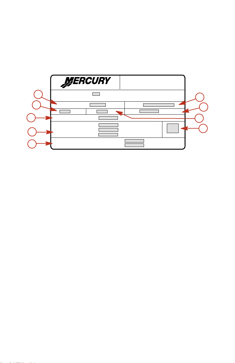
EMISSION CERTIFICATION LABEL
An emission certification label, showing emission levels and engine
specifications directly related to emissions, is placed on the engine at time
of manufacture.
EMISSION CONTROL
INFORMATION
This e ngine conforms to model year EPA regulations for Ma rine SI engines.
a
b
c
d
e
TIM ING (IN DE GREES):
Su pp ressor spar k pl ug:
Valv e C learan ce (C old) m m
Re fer to Ow ner' s Manual for require d m ainte na nce.
IDLE SPEED :
hp
Standa rd spa rk p lug :
:
GAP
a - Idle speed
b - Engine horsepower
c - Timing specification
d - Recommended spark plug
and gap
e - Valve clearance (if
applicable)
cc
Inta ke
Exhau st
FAM ILY:
FEL :
g/kW
h
f - Family number
g - Maximum emission output for
the engine family
h - Piston placement
i - Date of manufacture
f
g
h
i
ob01071
OWNER RESPONSIBILITY
The owner/operator is required to have routine engine maintenance
performed to maintain emission levels within prescribed certification
standards.
The owner/operator is not to modify the engine in any manner that would
alter the horsepower or allow emissions levels to exceed their
predetermined factory specifications.
Inspection And Maintenance Schedule
BEFORE EACH USE
• Check that lanyard stop switch stops the engine.
• Visually inspect the fuel system for deterioration or leaks.
• Check outboard for tightness on transom.
• Check steering system for binding or loose components.
57
Page 3

MAINTENANCE
• Visually check steering link rod fasteners for proper tightness. See
Steering Link Rod Fasteners.
• Check propeller blades for damage.
AFTER EACH USE
• Flush out the outboard cooling system if operating in salt or polluted
water. See Flushing the Cooling System.
• Wash off all salt deposits and flush out the exhaust outlet of the
propeller and gearcase with fresh water if operating in salt water.
EVERY 100 HOURS OF USE OR ONCE YEARLY,
WHICHEVER OCCURS FIRST
• Lubricate all lubrication points. Lubricate more frequently when used
in salt water. See Lubrication Points.
• Replace spark plugs at first 100 hours or first year. After that, inspect
spark plugs every 100 hours or once yearly. Replace spark plugs as
needed. See Spark Plug Inspection and Replacement.
• Replace fuel filter. See Fuel System.
• Replace compressor air intake filter. See Compressor Air Intake Filter.
• Inspect alternator belt. See Alternator Belt Inspection.
• Check corrosion control anodes. Check more frequently when used
in salt water. See Corrosion Control Anodes.
• Drain and replace gearcase lubricant. See Gearcase Lubrication.
• Check power trim fluid. See Checking Power Trim Fluid.
• Inspect battery. See Battery Inspection.
•
Check control cable adjustments.
•
Lubricate splines on the driveshaft and shift shaft.
• Check tightness of bolts, nuts, and other fasteners.
EVERY 300 HOURS OF USE OR THREE YEARS
• Replace water pump impeller (more often if overheating occurs or
reduced water pressure is noted).
BEFORE PERIODS OF STORAGE
• Refer to Storage procedure. See Storage section.
1.
1.
1.
Flushing The Cooling System
Flush the internal water passages of the outboard with fresh water after
each use in salt, polluted, or muddy water. This will help prevent a buildup
of deposits from clogging the internal water passages.
1. These items should be serviced by an authorized dealer.
58
Page 4
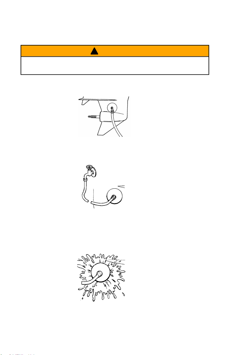
MAINTENANCE
Use a Mercury Precision or Quicksilver accessory (or equivalent) flushing
attachment.
WARNING
!
To avoid possible injury when flushing, remove the propeller. Refer to
Propeller Replacement.
1. Remove propeller. Refer to Propeller Replacement. Install the flushing
attachment so the rubber cups fit tightly over the cooling water intake.
ob01604
2. Attach a water hose to the flushing attachment. Turn on the water and
adjust the flow so water is leaking around the rubber cups to ensure
the engine receives an adequate supply of cooling water.
ob00570
3. Start the engine and run it at idle speed in neutral shift position.
IMPORTANT: Do not run engine above idle when flushing.
4. Adjust water flow (if necessary) so excess water continues leaking out
from around the rubber cups to ensure the engine is receiving an
adequate supply of cooling water.
ob00571
5. Check for a steady stream of water flowing out of the water pump
indicator hole. Continue flushing the outboard for 3 to 5 minutes,
carefully monitoring water supply at all times.
59
Page 5

MAINTENANCE
6. Stop the engine, turn off the water, and remove the flushing
attachment. Reinstall the propeller.
Flushing The Cooling System ‑ Models With
Accessory Hose Flush Attachment
Flush the internal water passages of the outboard with fresh water after
each use in salt, polluted, or muddy water. This will help prevent a build up
of deposits from clogging the internal water passages.
1. Thread a water hose into hose adaptor.
2. Remove dust cover and push the host adaptor into the flush connector
until it locks (snaps) in place.
a
a - Flush connector
b - Button
NOTE: Engine can be stopped or running at idle speed in neutral when
flushing the cooling system. Do not flush engine using a water source that
exceeds 6.5 kPa (45 psi).
3. Turn on the water and flush the cooling system for a minimum of 3
minutes.
NOTE: The hose adaptor shuts off the water flow whenever it is
disconnected from the flush connector.
4. Push button in to release the hose adaptor.
5. Reinstall dust cover.
b
d
c
ob01605
c - Hose adaptor
d - Dust cover
FREEZING TEMPERATURE
The water should be drained out of the engine flush hose if there is a
chance of freezing temperature. Drain water as follows:
1. Remove water hose from the hose adaptor.
2. Insert the adaptor only into the flush connector.
3. Tilt the outboard up until all the water has drained out of the hose.
60
Page 6
MAINTENANCE
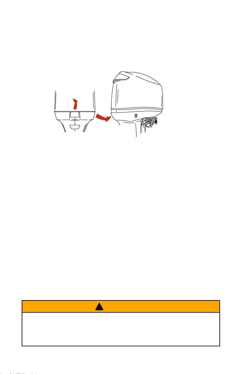
Top Cowl Removal And Installation
REMOVAL
1. Unlock the rear latch by pushing lever up.
2. Lift rear of cowl and disengage front hook.
ob01606
INSTALLATION
1. Engage the front hook and push cowl back over the cowl seal.
2. Push cowl down and move the rear latch lever down to lock.
Cleaning Care for Top Cowl
IMPORTANT: Dry wiping (wiping the plastic surface when it is dry) will
result in minor surface scratches. Always wet the surface before cleaning.
Follow cleaning and waxing procedure.
CLEANING AND WAXING PROCEDURE
1. Before washing, rinse the top cowl with clean water to remove dirt and
dust that may scratch the surface.
2. Wash the top cowl with clean water and a mild non‑abrasive soap.
Use a soft clean cloth when washing.
3. Dry thoroughly with a soft clean cloth.
4. Wax the surface using a non‑abrasive automotive polish (polish
designed for clear coat finishes). Remove the applied wax by hand
using a clean soft cloth.
Fuel System
WARNING
!
Avoid serious injury or death from gasoline fire or explosion. Carefully
follow all fuel system service instructions. Always stop the engine and do
not smoke or allow open flames or sparks in the area while servicing any
part of the fuel system.
61
Page 7

MAINTENANCE
Before servicing any part of the fuel system, stop engine and disconnect
the battery. Drain the fuel system completely. Use an approved container
to collect and store fuel. Wipe up any spillage immediately. Material used
to contain spillage must be disposed of in an approved receptacle. Any fuel
system service must be performed in a well ventilated area. Inspect any
completed service work for sign of fuel leakage.
FUEL LINE INSPECTION
Visually inspect the fuel line and primer bulb for cracks, swelling, leaks,
hardness, or other signs of deterioration or damage. If any of these
conditions are found, the fuel line or primer bulb must be replaced.
FUEL FILTER REPLACEMENT
Removal
1. Use the shaft of a screwdriver between the lugs on the filter cap and
unscrew the filter.
a
b
ob01673
a - Filter b - O‑rings
Installation
1. Lubricate the O‑ring seals with oil.
2. Install the fuel filter and tighten securely.
IMPORTANT: Visually inspect for fuel leakage from the filter while
squeezing the primer bulb until firm, forcing fuel into the filter.
DRAINING WATER FROM THE FUEL FILTER CHAMBER
NOTE: If a sufficient amount of water has accumulated in the fuel filter
chamber, the warning system will turn on. Draining the water from the fuel
filter chamber is required.
62
Page 8

MAINTENANCE
1. Pull the drain hose off the right side fitting. Hold open end of the hose
over a container.
2. Loosen drain screw and drain the fuel filter chamber.
b
a
a - Drain hose
b - Right side fitting
3. Retighten drain screw and reattach hose.
IMPORTANT: Visually inspect for fuel leakage from the drain screw by
squeezing the primer bulb until firm, forcing fuel into the chamber.
c - Drain screw
c
ob01674
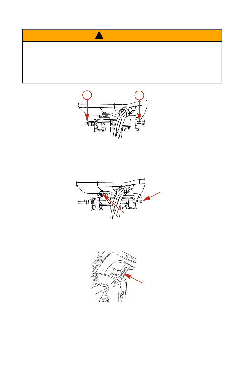
Steering Link Rod Fasteners
IMPORTANT: The steering link rod that connects the steering cable to the
engine must be fastened using special washer head bolt ("a" ‑ Part Number
10‑849838) and self‑locking nylon insert locknuts ("c" & "d" ‑ Part Number
11‑826709113). These locknuts must never be replaced with common nuts
(non‑locking) as they will work loose and vibrate off freeing the link rod to
disengage.
63
Page 9

MAINTENANCE
WARNING
!
Disengagement of a steering link rod can result in the boat taking a full,
sudden, sharp turn. This potentially violent action can cause occupants
to be thrown overboard exposing them to serious injury or death.
a
b
c
d
a - Special washer head bolt (10‑849838)
b - Flat washer (2)
c - Nylon insert locknut (11‑826709113)
d - Nylon insert locknut (11‑826709113)
Description Nm lb. in. lb. ft.
Special washer head bolt 27 20
Nylon insert locknut "d" 27 20
Nylon insert locknut "c" Tighten until seats, then back off 1/4 turn
Assemble steering link rod to steering cable with two flat washers and
self‑locking nylon insert locknut. Tighten locknut until it seats, then back
nut off 1/4 turn.
Assemble steering link rod to engine with special washer head bolt and
self‑locking nylon insert locknut. First torque bolt, then torque locknut to
specifications.
ob00676
Fuse Replacement
IMPORTANT: Always carry spare 5 and 20 AMP fuses.
The electrical wiring circuits on the outboard are protected from overload
by fuses in the wiring. If a fuse is blown, try to locate and correct the cause
of the overload. If the cause is not found, the fuse may blow again.
64
Page 10

MAINTENANCE
Open the fuse holder and look at the silver colored band inside the fuse. If
band is broken, replace the fuse. Replace fuse with a new fuse with the
same rating.
a
c
5
20
f
a - Good fuse
b - Blown fuse
c - SmartCraft data bus circuit ‑ 5 amp fuse
d - Accessories ‑ 20 amp fuse
e - Ignition coil circuit ‑ 20 amp fuse
f - Electric fuel pump/ECM driver power/oil pump circuit ‑ 20 amp
fuse
b
d
20
20
e
ob01607
Corrosion Control Anode
Your outboard has corrosion control anodes at different locations. An
anode helps protect the outboard against galvanic corrosion by sacrificing
its metal to be slowly corroded instead of the outboard metals.
Each anode requires periodic inspection, especially in salt water which will
accelerate the erosion. To maintain this corrosion protection, always
replace the anode before it is completely eroded. Never paint or apply a
protective coating on the anode as this will reduce effectiveness of the
anode.
65
Page 11

MAINTENANCE
The gearcase has two corrosion control anodes, one on each side. A third
anode is installed on the bottom of the transom bracket assembly.
a
a - Anode (2) on each side of
gearcase
b
b - Anode on transom bracket
assembly
ob00677
Battery Inspection
The battery should be inspected at periodic intervals to ensure proper
engine starting capability.
IMPORTANT: Read the safety and maintenance instructions which
accompany your battery.
1. Turn off the engine before servicing the battery.
2. Add water as necessary to keep the battery full.
3. Make sure the battery is secure against movement.
4. Battery cable terminals should be clean, tight, and correctly installed.
Positive to positive and negative to negative.
5. Make sure the battery is equipped with a nonconductive shield to
prevent accidental shorting of battery terminals.
Battery Information
CAUTION
!
Hex nuts must be used to secure battery leads to battery posts to avoid
loss of electrical power.
• Do not use deep cycle batteries. Engines must use a marine starting
battery with 1000 MCA, 800 CCA or 180 Ah.
• When connecting engine battery, hex nuts must be used to secure
battery leads to battery posts. Torque nuts to specification.
Description Nm lb. in. lb. ft.
Hex nuts 13.5 120
66
Page 12

MAINTENANCE
IMPORTANT: Battery cable size and length is critical. Refer to engine
installation manual for size requirements.
Decal needs to be placed on or near battery box for future service
reference. One 5/16 in. and one 3/8 in. hex nut are supplied per battery for
wing nut replacement. Metric hex nuts are not supplied.
NOTICE - DTS & Optimax Engines
DO NOT USE DEEP CYCLE BA TTERIES!
DTS (Digital Throttle and Shift) applications and
Optimax engines must use a marine starting
battery with 1000 MCA, 800 CCA, or 180 Ah.
rating.
IMPORT ANT :
Battery cable size and length is critical. Refer to
engine installation manual for size requirements.
Place decal on or near battery box for future service
reference. 5/16" and 3/8" hex nuts supplied for
wing nut replacement. Metric hex nuts not supplied.
Propeller Replacement
IMPORTANT: Propellers used on this product require the Mercury Marine
Flo‑Torq III type hub or equivalent.
13.5Nm (120 lbs. in.)
DO NOT
USE WING
NUTS.
37-895387
3486
WARNING
!
If the propeller shaft is rotated while the engine is in gear, there is the
possibility that the engine will crank over and start. To prevent this type
of accidental engine starting and possible serious injury caused from
being struck by a rotating propeller, always shift outboard to neutral
position and remove spark plug leads when you are servicing the
propeller.
1. Shift outboard to neutral (N) position.
N
ob00351
67
Page 13

MAINTENANCE
IMPORTANT: Refer to Spark Plug Inspection and Replacement for
removing spark plug leads.
2. Remove spark plug leads to prevent engine from starting.
ob00375
3. Straighten the bent tabs on the propeller nut retainer.
ob00376
4. Place a block of wood between gearcase and propeller to hold
propeller and remove propeller nut.
ob00377
5. Pull propeller straight off shaft. If propeller is seized to the shaft and
cannot be removed, have the propeller removed by an authorized
dealer.
6. Coat the propeller shaft with Quicksilver or Mercury Precision
Lubricants Anti‑Corrosion Grease or 2‑4‑C.
ob00378
68
Page 14

MAINTENANCE
Tube Ref No. Description Where Used Part No.
94
95
Anti-Corrosion Grease Propeller shaft
2-4-C Propeller shaft
IMPORTANT: To prevent the propeller hub from corroding and seizing to
the propeller shaft (especially in salt water), always apply a coat of the
recommended lubricant to the entire propeller shaft at the recommended
maintenance intervals and also each time the propeller is removed.
7. Flo‑Torq III Drive Hub Propellers ‑ Install forward thrust hub,
replaceable drive sleeve, propeller, thrust hub, propeller nut retainer
and propeller nut onto the shaft.
92-802867A
1
92-802859A
1
a b c d
a - Propeller nut
b - Propeller nut retainer
c - Rear thrust hub
e f
d - Propeller
e - Replaceable drive sleeve
f - Forward thrust hub
3223
8. Place a block of wood between gearcase and propeller and torque
propeller nut to specifications.
Description Nm lb. in. lb. ft.
Propeller nut 75 55
9. Secure propeller nut by bending three of the tabs into the thrust hub
grooves.
ob00422
69
Page 15

MAINTENANCE
Spark Plug Inspection And Replacement
WARNING
!
Avoid serious injury or death from fire or explosion caused by damaged
spark plug boots. Damaged spark plug boots can emit sparks. Sparks
can ignite fuel vapors under the engine cowl. To avoid damaging spark
plug boots, do not use any sharp object or metal tool such as pliers,
screwdriver, etc. to remove spark plug boots.
1. Remove the spark plug leads. Twist the rubber boots slightly and pull
off.
ob00375
2. Remove the spark plugs to inspect. Replace spark plug if electrode is
worn or the insulator is rough, cracked, broken, blistered or fouled.
ob00423
3. Set the spark plug gap to specifications.
ob00424
Spark Plug
Spark plug gap 0.80 mm (0.030 in.)
4. Before installing spark plugs, clean off any dirt on the spark plug seats.
Install plugs finger tight, and then tighten to the specified value.
Description Nm lb. in. lb. ft.
Spark plug 27 20
70
Page 16

MAINTENANCE
Compressor Air Intake Filter
The filter should be changed every 100 hours of operation, or once a
season.
IMPORTANT: Never run the engine without the air filter.
REMOVAL
1. Remove three screws and filter cover from engine.
2. Remove filter from the cover.
b
a
ob01608
a - Cover b - Filter
INSTALLATION
1. Install filter into cover.
2. Fasten filter cover with three screws.
Alternator Belt Inspection
WARNING
!
Avoid possible serious injury. Make sure engine is shut off and ignition
key is removed before inspecting belt.
1. Inspect the alternator belt and have it replaced by an authorized dealer
if any of the following conditions are found.
a. Cracks or deterioration in the rubber portion of the belt.
b. Belt surfaces rough or uneven.
71
Page 17

MAINTENANCE
c. Signs of wear on edges or outer surfaces of belt.
ob01609
Lubrication Points
1. Lubricate the following with Quicksilver or Mercury Precision
Lubricants Anti‑Corrosion Grease or 2‑4‑C.
Tube Ref No. Description Where Used Part No.
94
95
Anti-Corrosion Grease Propeller shaft
2-4-C Propeller shaft
92-802867A
1
92-802859A
1
• Propeller Shaft ‑ Refer to Propeller Replacement for removal and
installation of the propeller. Coat the entire propeller shaft with
lubricant to prevent the propeller hub from corroding and seizing
to the shaft.
ob00378
2. Lubricate the following with Quicksilver or Mercury Precision
Lubricants 2‑4‑C or Special Lubricant 101.
72
Page 18

MAINTENANCE
Tube Ref No. Description Where Used Part No.
Swivel bracket, tilt
34
95
Special Lubricant 101
2-4-C
support lever, tilt tube,
steering cable grease
fitting
Swivel bracket, tilt
support lever, tilt tube,
steering cable grease
fitting
• Swivel Bracket ‑ Lubricate through fitting.
• Tilt Support Lever ‑ Lubricate through fitting.
a
b
ob00683
a - Swivel bracket b - Tilt support lever
• Tilt Tube ‑ Lubricate through fitting.
92-802865A
1
92-802859A
1
ob01610
• Steering Cable Grease Fitting (If equipped) ‑ Rotate steering wheel
to fully retract the steering cable end into the outboard tilt tube.
Lubricate through fitting.
73
Page 19
MAINTENANCE
WARNING
!
The end of the steering cable must be fully retracted into the outboard
tilt tube before adding lubricant. Adding lubricant to steering cable when
fully extended could cause steering cable to become hydraulically
locked. A hydraulically locked steering cable will cause loss of steering
control, possibly resulting in serious injury or death.
a
a - Fitting b - Steering cable end
3. Lubricate the following with light weight oil.
• Steering Link Rod Pivot Points ‑ Lubricate pivot points.
b
ob01612
ob01613
Checking Power Trim Fluid
1. Tilt outboard to the full up position and engage the tilt support lever.
74
ob00687
Page 20

MAINTENANCE
2. Remove fill cap and check fluid level. The fluid level should be even
with the bottom of the fill hole. Add Quicksilver or Mercury Precision
Lubricants Power Trim & Steering Fluid. If not available, use
automotive (ATF) automatic transmission fluid.
ob00688
Gearcase Lubrication
When adding or changing gearcase lubricant, visually check for the
presence of water in the lubricant. If water is present, it may have settled
to the bottom and will drain out prior to the lubricant, or it may be mixed
with the lubricant, giving it a milky colored appearance. If water is noticed,
have the gearcase checked by your dealer. Water in the lubricant may
result in premature bearing failure or, in freezing temperatures, will turn to
ice and damage the gearcase.
Examine the drained gearcase lubricant for metal particles. A small amount
of metal particles indicates normal gear wear. An excessive amount of
metal filings or larger particles (chips) may indicate abnormal gear wear
and should be checked by an authorized dealer.
DRAINING GEARCASE
1. Place outboard in a vertical operating position.
2. Place a drain pan below outboard.
3. Remove vent plugs and fill/drain plug and drain lubricant.
a
b
ob00441
a - Vent plugs b - Fill/drain plug
75
 Loading...