


OP-904 PANEL MOUNT
INDICATOR USER’S MANUAL
optimascale.com

TABLE OF CONTENTS
Safety Precautions 1
Features
Specications
2
3
Display and Key Descriptions
Operating Instructions
Rear Panel
General Functions
Function Settings
Parameter Settings
6
7
8
9-10
5
4
Calibration Settings
11-14
Check Weighing Conguration
Cable Connection Manual
Troubleshooting
Contact Us
19
19
16-18
15

SAFETY PRECAUTIONS
For safe operation of the weighing indicator, please follow these
instructions:
● Calibration inspection and maintenance of the indicator are prohibited by non-pro-
fessional staff
● The indicator is a piece of static sensitive equipment; Please cut off power during
electrical connections
● Touching the internal components by hand is prohibited
● DO NOT exceed the rated load limit of the unit
● DO NOT step on the unit
● DO NOT jump on the scale
● DO NOT use this product if any of the components are cracked
● DO NOT use for purposes other then weight taking
● To avoid damaging the battery do not keep charger plugged in once battery is fully
charged
● Make sure the weight is not over the Max capacity as it could damage the load cell
inside
● Material that has a static electric charge could inuence the weighing. Discharge
the static electricity of the samples, if possible. Another
solution to the problem is to wipe both sides of the pan and the top of the case with
an anti-static agent
● Plug into a wall outlet to avoid interference with other wirings
● Calibration may be required before weighing when the scale is initially installed or
moved from a location
1

FEATURES
● LED 6 digit display
● Multiple weighing units: kg/lb/t
● Gross/Tare/Hold/Zero
● Check weighing feature
Technical Parameters
Hardware construction features
● Power supply: 24vDC
● Load cell excitation voltage: 5vDC±5%
● Load cell number: up to eight 350Ω
● Load cell sensitivity: 0~3.0mv/v
● Load cell connections: six wire
● Keyboard: six key
● Display: six digits red 7 segment LED display
● Relay output: 4 output, AC250v 5A
● Input: isolation voltage 2500V
● Analog output: 4~20mA/0~5v
● Serial port: RS232/RS485, baud rate 600~19200bit/s
● Operation temperature: -10 °C ~ +40 °C
● Operation humidity: ≤90%RH
● Storage temperature: -40 °C ~ +70 °C (32-104°F)
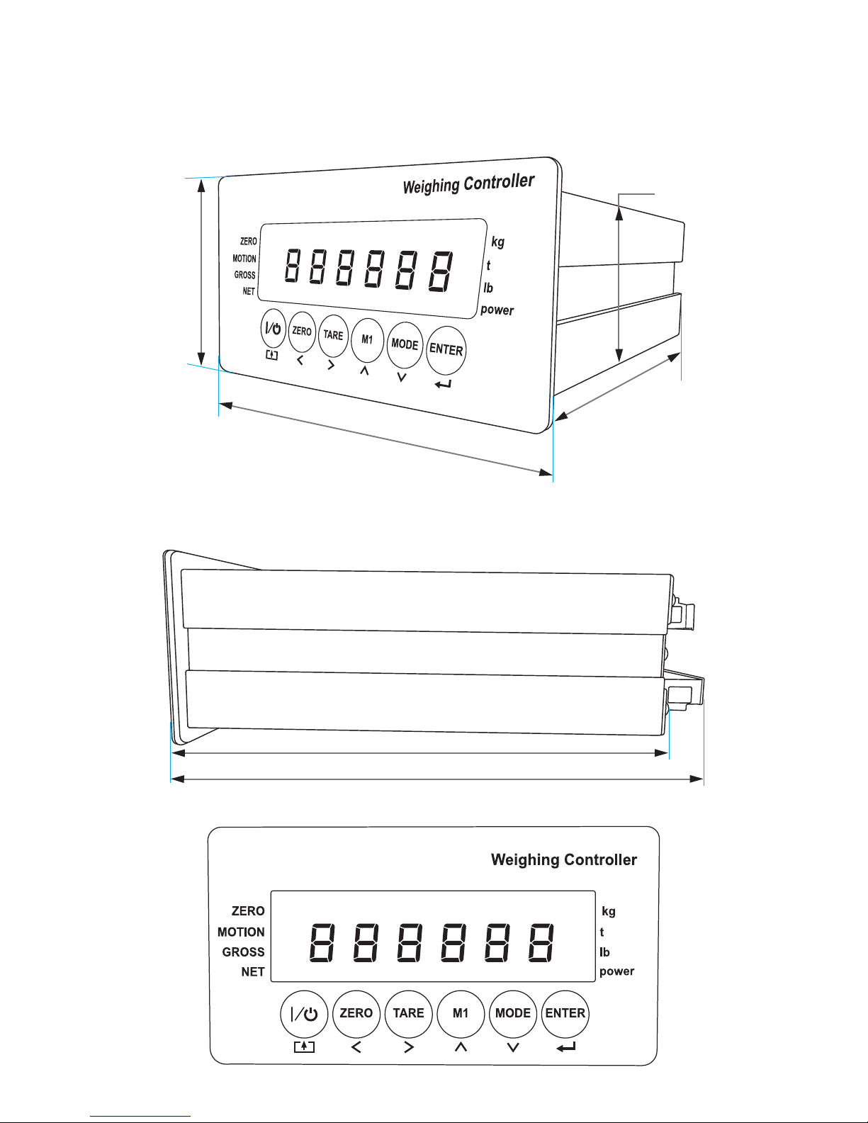
● Housing dimension: 92 x 45mm
● Front panel dimension: 102 x 55mm
● Trepanning dimension: 93 x 46mm
Software features
● Max sampling speed: 120SPS
● AD digital lter
● Digital calibration
● Batching or dosing functions
2
2.16”
SPECIFICATIONS
FIGURE 1: INDICATOR MEASUREMENTS
1.78”
5.46”
4”
5.6”
6.1”
3

DISPLAY AND KEY DESCRIPTION
|/
ZERO Zero’s the scale
TARE 1. Resets the scale to zero when there is something on the scale
M1 Displays Gross/Net weight
MODE Setpoint parameter set
ENTER Enter key
Zero Indicates that you have zero’d the scale
Motion The weight on the scale is unstable
Gross Shows you are in Gross weight mode (includes tare); default mode
Net Shows you are in Net weight mode (weight without tared weight)
kg The weight is shown in kilograms
t The weight is shown in tons
lb The weight is shown in pounds
Power Flashes red = low battery, Solid red = charging, Green = fully charged
Over Flashes when weight is higher than set alarm parameter
Powers the Indicator On or Off if held for 2 seconds
(ex. Tare out the weight of a pallet to weigh only the product on it)
2. Clears the tare to see the gross weight (pallet + product)
Accept Flashes when weight is within the set alarm parameters
Under Flashes when weight is lower than set alarm parameter
Save and Exit
Arrow keys
Return/Enter
4

OPERATING INSTRUCTIONS
Power On
● Turn on the power by pressing the power button for 2 seconds. Once on, the scale
will ash the voltage and then begin to auto-check and count down from 0-9
sequentially before entering the weighing mode
Note: Anything on the scale before powering on will automatically be tared out.
Zeroing
● The zero function is used only when the scale is empty and is not at gross zero due
to material build up
● Pressing the ZERO key will reset your scale to 0
● Depending on what your manual zero range parameter is set to, you can zero out
any number within your set selection, after that you will receive an error and will
need to tare out the weight
Tare Function
● The Tare function is used when you only wish to see the current change in weight,
not the entire amount of weight that is on the scale
● When the indicator is in gross mode (gross light is shown) pressing the TARE key
will Tare the current weight on the scale and enter the net mode (net light shown)
● For example if you are using a container add the container to the scale, press tare
and the display will show the gross light and reset back to 0
● Add your product to the scale to weigh without the weight of the container
● To exit Tare mode press the TARE key again to enter gross mode and you will see
the total weight of the container and the product
Note: If you remove the container the scale will show the minus weight of the container
5
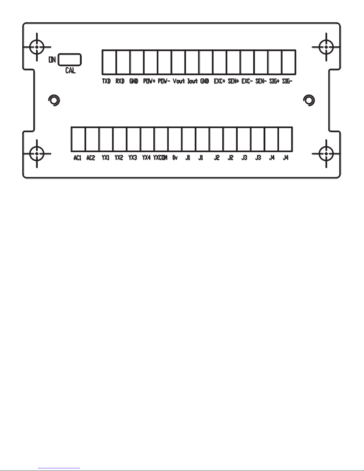
REAR PANEL
Connection denition:
Power: POW+ POW- for 24VDC, AC1 AC2 for 220VAC
Load cell: EXC+ SEN+ EXC- SEN- SIG+ SIG
Serial communications: TXD RXD GND for RS232, A B for RS485
Analog output: Vout Iout GND
Relay output: J1 J1 J2 J2 J3 J3 J4 J4
Input: YX1 YX2 YX3 YX4 YXCOM 0vTo exit Tare mode press the TARE key again to enter
gross mode and you will see the total weight of the container and the product
Note: If you remove the container the scale will show the minus weight of the container
6

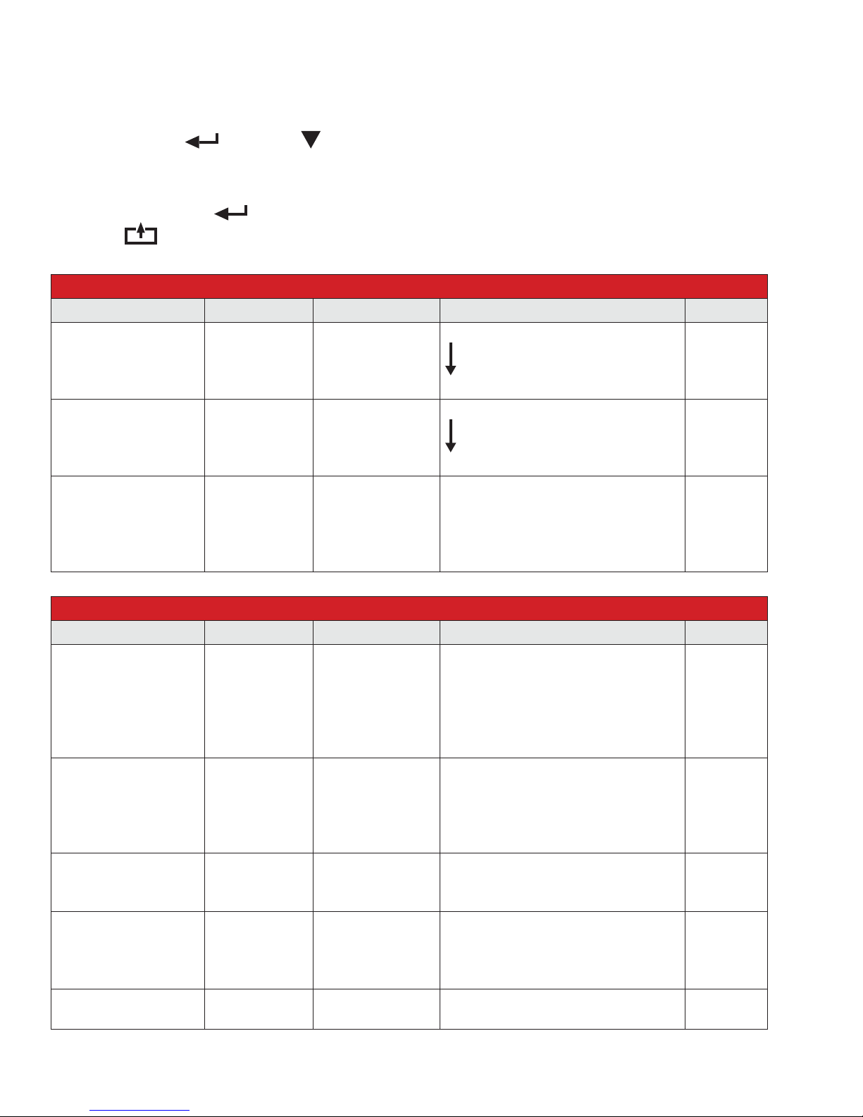
GENERAL FUNCTIONS
Function setup and operation procedure:
Function Operation Display Remark
Enter calibration mode Turn the calibration switch to “ON” 01 CSP 4
Enter function setting
Check weighing setpoint
parameter setting
Enter to test mode
Reset all parameters back
to default
Reset general function
parameters back to default
Parameter Settings, Key meaning
Key Meaning
Save and Exit
Move the ashing digit to the left
Move the ashing digit to the right
Weight mode, press
Weight mode, press
Turn power on, press
Turn power on, turn the calibration
switch to “ON”, press
Turn power on, press
and
and
and
and
01 FnC 3.3
1.FinAL 5
1. dsp 7.1
i.ALL 7.2
1 FnC 7.2
Increase the ashing digit
Decrease the ashing digit
Conrm
7

FUNCTION SETTINGS
Press and at the same time to enter the function settings
The screen will display “01 FnC” for function setting
Press
Press
Press
Press
Press
Press
to display “02 232” for serial port interface
to display “03 Sq ” for weight comparison procedures
to display “04 AnL” for analog current output
to display “05 In ” for external input interface
to enter the next menu level
to save and exit out of this menu and restart
and
Weighing Mode
01 FnC
01 FnC
01 FnC
01 FnC
FnC 01
232 01
Sq 01
AnL 01
8
01 FnC
In 01
INDICATOR PARAMETER SETTINGS
To enter parameter settings, follow the procedure below:
1. Press ENTER and MODE at the same time for 2 seconds to enter the function settings
2. Navigate through the settings as shown in the table below by using the arrow keys and return
keys as labeled under each indicator button
3. Press the ENTER key to enter/edit the parameter setting
Press the
Function Item Parameter Description Default
Digital Filter 1
Digital Filter 2
Rate for display
rewrite
key to save and exit settings at any time
01 FnC Function Parameter Code
FnC 01
FnC 02
FnC 03
00
01
...
10
00
01
02
03
01
05
10
20
120
Greater
Less
Greater
Less
1 times/sec
5 times/sec
10 times/sec
20 times/sec
120 times/sec
03
02
10
02 232 Serial Port Interface
Function Item Parameter Description Default
Baud Rate
Transmit Mode
Data Format
Transmit Time
Address for Multicomputer
232 01
232 02
232 03
232 04
232 05
00
01
02
03
04
05
00
01
02
03
04
00
01
02
00
01
02
03
00
01~99
600bit/s
1200bit/s
2400bit/s
4800bit/s
9600bit/s
19200bit/s
close serial port
continuous
print mode
stable send
command mode
format 1
format 2
print format
open
1 sec
2 sec
5 sec
Only one
Address (bcd)
04
01
00
00
00
9

03 Sq Weight Comparison Procedures
Function Item Parameter Description Default
Batching Mode
Control Mode
Comparison Format
Start Delay
Stable Time
sq 01
sq 02
sq 03
sq 04
sq 05
00
01
02
03
04
01
02
03
01
02
00
01
...
10
00
01
...
10
normal batch
less-in weight
comparison
manual start
auto
for custom
net
gross
no delay
1 sec delay
…
10 sec delay
no wait
1 sec wait
…
10 sec wait
01
01
01
01
03
04 Analog Current Ouput
Function Item Parameter Description Default
Signal output
Data format
Maximum weight
Zero adjust
Linearity adjust
Output range limit
AnL 01
AnL 02
AnL 03
AnL 04
AnL 05
AnL 06
00
01
02
00
01
010000
4mA/0mA/0v
20mA/5v
00
01
4~20mA current
0~20mA current
0~5v voltage
display weight
gross weight
when max analog output weight
Press
Press
no limit
limit
or to adjust output
or to adjust output
00
00
010000
4
20
00
05 External Input Interface
Function Item Parameter Description Default
INPUT1
INPUT2
INPUT3
INPUT4
IN 01
IN 02
IN 03
IN 04
00
01
02
03
04
05
06
no function
zero
tare
gross
hold
total
print
01
02
05
06
10

CALIBRATION SETTINGS
To enter calibration settings, follow the procedure below:
1. In weighing mode, make sure calibration switch is set to “ON”
2. The display will show “01 CSP” meaning you entered the calibration parameter code
● Press to enter the next step level
● Follow the steps in the parameters to set up your calibration
3. Press to display “02 CAL” General calibration
● Follow the steps to calibrate your scale
4. Press to display “03 CUo” Sensitivity calibration
● Follow the steps to set lters and manage the sensitivity of your scale
5. When you are done with calibrating, make sure to turn the switch to “OFF”
6. The screen will display “End” , save the data and restart
Weighing Mode
Calibration switch set to “ON”
01 CSP
Calibration
Set-up
02 CAL
03 CUo
Sensitivity
Calibration
Calibration
Calibration switch set to “OFF”
Save Data & Restart
11

“01 CSP” Calibration Parameter Code
01 CSP Calibration Parameter Code
Function Item Parameter Description Default
Unit
Decimal point
Division
Max Capacity
Zero-Setting range
Initial zero-setting
range
Automatic
zero-setting range
Automatic
zero-setting time
Stable time
Stable range
Automatic zero
Preserved Menu
CSP 01
CSP 02
CSP 03
CSP 04
CSP 05
CSP 06
CSP 07
CSP 08
CSP 09
CSP 10
CSP 11
01
02
03
00
01
02
03
04
01
02
05
010000
00
01
02
00
01
02
05
10
00
05
10
20
00
01
02
03
00
01
02
01
02
05
10
00
02
05
10
20
kg
lb
t
none
1 decimal point
2 decimal point
3 decimal point
4 decimal point
division size
Max capacity
0
±1%
±2%
0
±1%
±2%
±5%
±10%
0
0.5d
1d
2d
0
1 sec
2 sec
3 sec
fast
medium
slow
1d
2d
5d
10d
no
-2d
-5d
-10d
-20d
01
00
02
1000
02
10
05
01
01
02
02
CSP 12
12

“02 CAL” Calibration
In weighing mode set calibration switch to “ON”
01 CSP
Calibration press
To enter calibration press
Zero calibration press
Skip zero calibration press
Display zero code
3 seconds
Weight calibration press
Skip weight calibration press
02 CAL
ZERO
288888
SPAN
Use
Once the weight is stable press
Sensitivity
3 seconds, calibration done
Set calibration switch to “OFF”
You are nished
Note: Zero calibration, can be no more than 5mv.
to set the weight
01000kg
120000
02 CAL
END
13

“03 CUo” Sensitivity Calibration
In weighing mode set calibration switch to “ON”
01 CSP
Sensitivity Calibration press
To enter calibration press
Zero calibration press
Skip zero calibration press
Auto gather zero code
Or press
to enter zero calibration
Sensitivity calibration press
Skip sensitivity calibration press
to set zero code
03 CUo
ZERO
288888
SPAN
Use
enter press
Sensitivity calibration done
Set calibration switch to “OFF”
You are nished
Sensitivity = 100000 x load cell full scale output x weigh-
ing meter capacity /(N x Load cell capacity)
to set the sensitivity
120000
02 CUo
END
14

CHECK WEIGHING CONFIGURATION
Weighing mode press to go enter parameters
Display Function
1. FinAL Final value
2. SP1 SP1 value
3. SP2 SP2 value
4. SP3 SP3 value
F. FALL Free fall value
6. oVer Over value
7. UndEr Under value
8. Z.bAnd Zero band
Warning: set FinAL > SP1 > SP2 > SP3 > F. Fall
set Sq01=1: net weigh
Signal Output Condition Relay Output
SP1 Net ≥ Final-SP1 J1
SP2 Net ≥ Final-SP2 J2
SP3 Net ≥ Final-SP3 J3
Free Fall Net ≥ Final-F.FALL J4
Set Sq01=3:
Signal Output Condition Relay Output
HI Net ≥ SP1 J1
OK SP1 ≥Net ≥ SP2 J2
LO Net < SP2 J3
15

CABLE CONNECTION MANUAL
Power
POW+ 24VDC+
POW- 24VDCAC1 220VAC
AC2 220VAC
Load cell
EXC+
SEN+
EXCSENSIG+
SIG-
NOTE: use 4-wire load cell need EXC+ and SEN+ short connect, EXC- and SEN- short
connect.
Serial Port
TXD RS232 transmission RXD RS232 receive GND RS232 GND A RS485 A B RS485 B
Analog Output
Vout 0~5v voltage, load more than 1kΩ
Iout 4~20mA current, load span 100~500Ω
GND GND
16

Relay Output
J1 J1 rst group relay output
J2 J2 second group relay output
J3 J3 third group relay output
J4 J4 fourth group relay output
Relay Output Connecction diagram
Note: Use common connection, put one of J1, J2, J3, J4 short connect.
Common connection diagram
17

Input
YX1 rst group input
YX2 second group input
YX3 third group input
YX4 fourth group input
YXCOM input common
0v out connect power GND
Input Diagram
Out connect power input diagram
Note: Using out elctric power needs more than 3V battery charge, Out electric power
less than 24V.
18

Error Codes
Error Reason Solution
UUUUUU
nnnnnnn
ERR1
ERR2
ERR3
ERR4
ERR5
ERR6
TROUBLESHOOTING
1. Overload
2. Wrong connection with load cell
3. Load cell has quality problem
1. Calibration is no good
2. Wrong connection with load cell
3. Load cell has quality problem
During calibration, weight is not used or
the weight is above the max. capacity
During calibration, the weight is below
the minimum required weight
During calibration, the input signal is
negative
During calibration signal is unstable After the platform is stable, start calibration
EEPROM Error Change PCB
Exceed Zero Range See Q&A section
1. Reduce the weight
2. Check load cell connection
3. Inspect load cell; Check the input/output
4. See Q&A section
1. Make sure scale is level
2. Check load cell connection
3. Check load cell input and output resistance
4. See Q&A section
Use correct weight within the dened range
The calibration weight minimum is 10% of
the max. capacity set in C04.
Recommended to use 60%-80% of max.
capacity if possible
1. Check all wire connections
2. Check load cell
3. Recalibrate
4. PCB replacement needed if steps 1-3 fail
CONTACT US
Please e-mail sales@optimascale.com for any sales related questions.
Please e-mail support@optimascale.com for any support related questions.
Don’t forget to visit our website at:
optimascale.com
19

 Loading...