

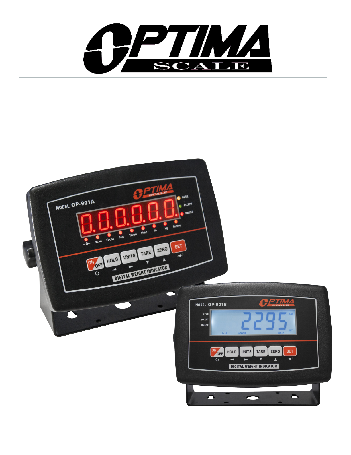
OP-901 SERIES INDICATOR
USER’S MANUAL
(OP-901A, OP-901B Series)
optimascale.com

TABLE OF CONTENTS
Safety Precautions 1
Preparations and Set Up 1
Features 2
Specications 3
Power Supply 4
Displays 5
Display and Key Descriptions 6
Operating Instructions 7-8
Calibration 9-10
Indicator Parameter Settings 11-13
Denitions 14
Connectors 15
Communication Mode 16
Troubleshooting 17
Contact Us 17

SAFETY PRECAUTIONS
For safe operation of the weighing indicator, please follow these
instructions:
● Calibration inspection and maintenance of the indicator are prohibited by non-pro-
fessional staff
● Please ensure that the indicator rests on a stable surface
● The indicator is a piece of static sensitive equipment; Please cut off power during
electrical connections
● Touching the internal components by hand is prohibited
● DO NOT exceed the rated load limit of the unit
● DO NOT step on the unit
● DO NOT jump on the scale
● DO NOT use this product if any of the components are cracked
● DO NOT use for purposes other then weight taking
● To avoid damaging the battery do not keep charger plugged in once battery is fully
charged
● Make sure the weight is not over the Max capacity as it could damage the load cell
inside
● Material that has a static electric charge could inuence the weighing. Discharge
the static electricity of the samples, if possible. Another
solution to the problem is to wipe both sides of the pan and the top of the case with
an anti-static agent
Please take anti-static prevention measures
Any accumulated charge on the body of the human operator should be discharged rst
before opening the protective container with ESDS devices inside. The discharge can
be accomplished by:
● Putting a hand on a grounded surface or, ideally, by wearing a grounded Anti-static
Wrist Strap and an Anti-static Mat
PREPARATION & SET UP
● Plug into a wall outlet to avoid interference with other wirings
● Turn on the balance while there is no load
● We suggest to warm-up the balance by powering on 5 minutes before use for
accurate weighing
● Calibration may be required before weighing when the balance is initially installed
or moved from a location
1

FEATURES
Main Functions
● Multiple weighing units: (kg/lb)
● General weighing: Gross/Tare/Zero
● Multiple Hold functions (animal weighing, peak-hold, manual-hold, auto-hold)
● Overload / Underload indication
● Print option
● Low battery reminder
● Automatic Power off (power saving mode)
Technical Parameters
● Accuracy class: 3000 e
● Stimulating voltage: +3.3 VDC
● A/D converting speed 10 SPS
● Load signal range: 0~12.8mV
● Load capacity: can connect 4 pcs 350Ω load cell at most
● Interval: 1/2/5/10/20/50
● Display: 6 digits LED/LCD, word height 20.3mm
● Interface: RS232C
● Baud rate: 1200/2400/4800/9600
● Battery: 4V/4Ah rechargeable battery; 110/220VAC
● AC power: AC 100-250V (use only the included 9V adapter supplied)
● Operation temperature: -10 °C ~ +40 °C
● Operation humidity: ≤90%RH
● Storage temperature: -40 °C ~ +70 °C (32-104°F)
2

SPECIFICATIONS
INDICATOR MEASUREMENTS
6 in.
power supply
8.7 in.
load cell port
rs232 port
battery box
3.2
in.
6 in.
3

POWER SUPPLY
AC Adapter
The indicator is charged by an ac adapter, plug the adapter directly into the “DC” pin
located at the back of the indicator. We recommend to plug into a wall outlet to avoid
interference with other wirings. A 110 to 220V AC adapter should be provided with your
indicator. Please use only the AC adapter provided to prevent damage to your indicator.
Battery
OP-901 comes with a rechargeable battery, please charge the internal battery fully
before rst time use for 10-12 hours to prevent low voltage resulted from self leakage
of batter. Once charged the battery should last for 45 hours. To keep the battery in best
condition, fully discharge the battery every month by leaving the indicator on until the
indicator powers off, and then recharge fully. If the battery is not going to be used for a
long period of time it is recommended to remove it to avoid leakage.
On OP-901A
● When the Battery is low the battery indicator light ashes red
● During charging the red light will stay lit
● The light will turn green once fully charged
ON OP-901B
● symbol will indicate battery’s charge
● symbol indicates that the battery needs to be charged
4

OP-901A (LED)
OP 901B (LCD)
5

DISPLAY AND KEY DESCRIPTION
ON/OFF Powers the Indicator On or Off if held for 2 seconds
HOLD 1. Peak hold - Grabs the highest weight (for tension and pulling force)
2. Data hold - Holds the current weight value (ex. for use with weighing
moving animals)
UNITS Shifts between weighing units (kg/lb)
TARE 1. Zero’s the scale. Used when using a container to hold objects
2. Clears the tare to see the gross weight
ZERO Zero’s the scale
SET Works with the “On/Off” button to enter and exit calibration
The scale is at zero
The scale is stable
Gross Shows you are in Gross weight mode (includes tare); default mode
Net Shows you are in Net weight mode (without tare)
Tared Shows you are in Counting mode
Hold Shows you are in Hold mode
lb The weight is shown in pounds
kg The weight is shown in kilograms
Battery Flashes red = low battery, Solid red = charging, Green = fully charged
Over Flashes when weight is higher than set alarm parameter
Accept Flashes when weight is within the set alarm parameters
Under Flashes when weight is lower than set alarm parameter
Power
Arrow keys
Enter/Return
6

OPERATING INSTRUCTIONS
Power On
● Turn on the power by pressing the power button for 2 seconds. Once on, the scale
will ash the voltage and then begin to auto-check and count down from 0-9
sequentially before entering the weighing mode
Note: Anything on the scale before powering on will automatically be tared out.
Zeroing
● The zero function is used only when the scale is empty and is not at gross zero due
to material build up
● Pressing the ZERO key will reset your scale to 0
● Depending on what your manual zero range parameter is set to, you can zero out
any number within your set selection, after that you will receive an error and will
need to tare out the weight
Unit Selection
● To switch between measuring units (kg, lb, oz) press the UNITS key
Tare Function
● The Tare function is used when you only wish to see the current change in weight,
not the entire amount of weight that is on the scale
● When the indicator is in gross mode (gross light is shown) pressing the TARE key
will Tare the current weight on the scale and enter the net mode (net light shown)
● For example if you are using a container add the container to the scale, press tare
and the display will show the tare symbol and reset back to 0
● Add your item to the scale to weigh without the weight of the container
● To exit Tare mode press the TARE key again to enter gross mode and you will see
the total weight of the container and the item
Note: If you remove the container the scale will show the minus weight of the container
7

Hold
In the parameter settings you can choose one of these 5 hold options
1. Peak Hold: Grabs the highest weight (for materials testing, ie. tension and pulling
force)
● Press the HOLD key then add weight to the scale
● The indicator will show the highest weight it recorded and hold it on the screen until
a higher weight is placed on the scale
2. Manual Hold: Grabs the current weight and holds it so it will not change/uctuate
● While weighing, press HOLD and the indicator will hold the current weight on the
screen until HOLD is pressed again
3. Auto Hold: If the weight on the scale is above 20d and is stable, the indicator will
hold that weight on the screen for 3 seconds then go back to general weighing
● Pressing the hold key is unnecessary, holding is done automatically when the scale
is stable
4. Average Hold: Used for animal weighing, the indicator will display the average
weight sampled from 3 or 5 seconds (Set in the C12 Parameter)
● Add animal to scale and press HOLD
● Indicator screen will show “
weight from those 3 seconds
● Press HOLD again to exit holding mode
” for 3 or 5 seconds, then display the average
LOC
5. Auto Average Hold: Used for animal weighing, the indicator will display the average weight sampled from 3 or 5 seconds without the need to press the HOLD key.
If the weight on the scale is above 20d and is stable, the indicator will start grabbing
the average weight sampled from 3 seconds.
● Begin loading animal to scale, after 5 seconds the Indicator screen will show “
for 3 seconds
● It will then display the average weight from those 3 seconds for 3 seconds and then
repeat the process
Print
● If the indicator is connected to a printer and the communication mode is set to print
mode (C18 =2) and the weight on the scale is stable press and hold the SET key to
print the current weight
Print out example:
Net weight
N.W.: 25.6lb
Tare weight
T.W.: 10.3lb
Gross weight
G.W.: 35.9lb
Print out number
NO. 01
LOC
”
8

CALIBRATION PROCEDURE
1. Turn on the scale by holding ON/OFF for 2 seconds.
2. Press ON/OFF and SET together to access the setup menu.
3. If done correctly, the display should now show
4. Press SET to access the C1 channel. The display should show [C1 #].
5. Press ZERO to change the value of C1 to [
6. up in pounds.)
7. Press SET to set the value. The display will now show
8. Press SET to access the C2 channel. The display should show [C2 #].
9. Press ZERO to change the setting to the decimal places desired.
(The C2 channel is used to adjust the decimal point on the scale. A value of 1 means
there is one digit behind the decimal point.)
10. Press SET to set the value. The display will now show
11. Press SET to access the C3 channel. The display should show [C3 #].
12. Press ZERO to cycle through the values until the desired graduation appears.
(The C3 channel adjusts the divisions on the scale. A value of 1 selected and C2 set
to 1, the scale will read in 0.1 lb. increments.)
13. Press SET to set the value. The display will now show
14. Press SET to access the C4 channel. The display will show [######].
15. Enter in the maximum capacity you want to use for this scale by using HOLD and
UNITS to move the cursor left and right, and TARE and ZERO to move the
values down and up. (The C4 channel is used to enter in the max capacity of the
scale; Make sure this doesn’t exceed the max capacity of the scale; Max capacity
C1 2
C01
.
]. (The value of 2 sets the scale
.
C02
.
C03
.
C04
divided by the increment set in C02 and C03 above cannot exceed 5000)
16. Press SET to set the value. The display will now show
17. Press SET to access the C5 channel. The display should show [
18. The C5 channel calibrates zero on the scale. Make sure the scale is empty.
19. Press ZERO to change the value to 1.
20. Press SET . The display will count down from 10-1 while the scale is
calibrating zero. When the display shows 0 the zero calibration is complete.
21. Press SET to continue. The display will now show
22. Press SET to access the C06 channel. The display will show [
23. The C6 channel is used to calibrate the scale with a known weight. Press ZERO to
set the value of C6 to [
then show [######].
24. Enter the calibration weight value you will use (at least 10% of max capacity you set
in C04 by using HOLD and UNITS to move the cursor left and right, and TARE
and ZERO move the values down and up.
25. Place the calibration weight you have on the empty scale and press SET .
26. The scale will count down from 10 to 0. Once 0 has been reached, the display will
show
CALEnd
.
C6 1
]. Press SET . The display will ash
C06
C05
.
.
C5 0
C6 0
].
SPAN
].
, and
9

CALIBRATION cont.
27. Press SET to continue. The display will now show
28. Press ON/OFF to save and exit the setup menu.
29. The scale has now been calibrated. The display will show the value of the calibration
weight on the scale.
30. If the scale does not show the value of the calibration weight, check that the feet on
the platform are not screwed in too tightly, and verify that the platform is level.
31. Unload the scale; the display should read 000000.
32. If the scale does not display 00000, check that the feet on the platform are not
screwed in too tightly, and verify that the platform is level.
C07
.
10

INDICATOR PARAMETER SETTINGS
The parameter settings menu has a calibration section (C01 to C06 explained above) and a
parameter settings section (C07 and up).
To access the calibration section the seal switch (located at one corner of the PCB) must be
OFF. This will allow access to all C01 and up settings. If the seal switch is ON, then only C08 and up
can be accessed by the user. If you break the ofcial seal by opening the back of the indicator to
access the seal switch, you may need to have the indicator recertied. Be sure to adjust the seal
switch back to the original setting after calibration/conguration has been performed.
To enter calibration/parameter settings, follow the procedure below:
1. Press and hold the ON/OFF and SET key at the same time for 2 seconds
2. Navigate through the settings (C01 to C45) as shown in the table 4 below by using the arrow
keys and enter key as labeled under each indicator button
3. Press the SET key to enter/edit the parameter setting
4. Press the ON/OFF key to save and exit settings at any time
Table 1. Calibration Parameter Settings
Function Parameter Settings/Options
Weighing Unit
Decimal Setting
Division/
Graduation Setting
(readability of the least
signicant digit)
Maximum Capacity
Zero Calibration
Calibration
C01
C02
C03
C04
C05
C06
1 = kg
2 = lb
0 = no decimal
1 = #.#
2 = #.##
3 = #.###
4 = #.####
options: 1/2/4/10/20/50
Example with no decimal places (ie C02=0)
1 = 1 lb
2 = 2 lb
5 = 5 lb
10 = 10 lb
20 = 20 lb
50 = 50 lb
set max capacity ex. 100kg = [0100.00]
0 = zero calibration
1 = set the zero calibration
Note: Before calibrating please ensure scale is empty and the stable
light is on.
When calibrating the Indicator will count down from 10 to 0
0 = calibration not needed
1 = ready to calibrate with calibration weight
Note: When calibrating the display will ash SPAn, telling you to
input the value of the calibration weight you will be using.
Once set the scale will count down from 10 to 0 and display CalEnd, and the calibration will be complete.
11

Table 2. Indicator Parameter Settings
Function Parameter Settings/Options
Restore Default
Settings
Warning Tone
Power Off
Automatically
Power Saving Mode
Hold Function
Hold Time
Upper Limit Alarm
Lower Limit Alarm
Inner Code Display
Communication
Setting
Baud Rate
Manual
Zero Range
C07
C08
C09
C10
C11
C12
C13
C14
C15
C18
C19
C20
0 = do not restore
1 = restore to default settings
0 = turn off warning tone
1 = turn on warning tone
0 = turn off auto power off
10 = power off automatically if no change within 10 minutes
30 = power off automatically if no change within 30 minutes
60 = power off automatically if no change within 60 minutes
LED Version OP901A:
0 = turn off power saving setting
3 = turn off display if no change within 3 minutes
5 = turn off display if no change within 5 minutes
LCD Version OP901B:
0 = turn off the backlight
1 = backlight only when the weight changes or keyboard is pressed
2 = constant backlight
0 = turn off hold function
1 = Peak hold - Grabs the highest weight
2 = Manual hold - Grabs the current weight
3 = Auto hold - Automatically holds data when stable
4 = Average hold - for animal weighing, averages the weight from a
sample of 3 or 5 seconds (Set in parameter C12)
5 = Auto Average hold - Average hold without the need to press the
hold key
If you chose C11=4 this setting allows you to set how many
seconds it samples to obtain an average weight
3 = 3 seconds
5 = 5 seconds
Set upper limit within the max. capacity
Set lower limit within the max. capacity
Check the inner code (raw data)
Set the serial interface data output method:
0 = Turn off serial interface data output
1 = Continuous sending mode, connect remote display
2 = Print mode, connect printer
3 = n/a
4 = PC continuous sending mode, connect computer
0=1200 (for remote display)
1=2400
2=4800
3=9600
0 = turn off manually zero setting
1 = ±1% max capacity
2 = ±2% max capacity
4 = ±4% max capacity
10 = ±10% max capacity
20 = ±20% max capacity
100 = ±100% max capacity
12

Function Parameter Settings/Options
Initial Zero Range
Zero Tracking
Zero Tracking Time
Overload Range
C21
C22
C23
C24
0 = no initial zero setting
1 = ±1% max capacity
2 = ±2% max capacity
5 = ±5% max capacity
10 = ±10% max capacity
20 = ±20% max capacity
0= turn off zero tracking
0.5 = ±0.5d d = division
1.0 = ±1.0d
2.0 = ±2.0d
3.0 = ±3.0d
4.0 = ±4.0d
5.0 = ±5.0d
Note: the zero tracking range can not be bigger than manual zero
range
0 = turn off zero tracking time
1 = 1 second
2 = 2 seconds
3 = 3 seconds
00 = turn off overload range
01-99d = overload range setting d = division
Negative Display
Standstill Time
Standstill Range
Digital Filter
(for ltering moving
weight, such as
animals)
Noise Filter
Print Time and Date
Gravity of Calibration
Location
Gravity of Destination
Version No.
Input Signal
C25
C26
C27
C28
C29
C30
C36
C37
C38
C39
0 = -9d
10 = -10% max. capacity
20 = -20% max. capacity
50 = -50% max. capacity
100 = -100% max. capacity
0 = quick
1 = medium
2 = slow
1 = ±1d d= division
2 = ±2d
5 = ±5d
10 = ±10d
0 = turn off dynamic lter
1 = Low dynamic lter
3 = Medium dynamic lter
5 = High dynamic lter
0 = turn off noise lter
1 = Low
2 = Medium
3 = High
0 = yy.mm.dd
1 = mm.dd.yy
2 = dd.mm.yy
3 = yy.mm.dd
9.7000 - 9.9999
9.7000 - 9.9999
0 = Input Signal Direction Normal
1 = Input Signal Direction Reversed
13

HELPFUL DEFINITIONS
Division: The amount of increments a scale offers. How accurate the scale can be
Capacity: the maximum amount the scale can contain
Initial Zero Range: The percentage of weight allowed on the scale when indicator is powered
on that will automatically zero.
example: If initial zero range is set to 10% of the max. capacity and your max. capacity is
100lbs, you can place up to 10lbs of weight on the scale and when the indicator is powered on, it
will automatically zero out the weight.
Manual Zero Range: The percentage of weight allowed on the scale where the indicator will let
you manually zero (anything above this percent will be tared)
Zero Tracking Range: A subset to the manual zero range; if the weight on the scale
is not stable, the zero tracking range still allows you to zero within a set division of the
scale
Zero Tracking Time: A subset to the zero tracking range, it is the time allowed for the
scale to fall within the zero tracking range tolerance and still qualify to be zero’d
Overload Range: Weight allowance that is out of the set calibrated range. Adds a
tolerance to the calibrated max. capacity without having to recalibrate.
example: If your scale has a max. capacity of 1000lbs with a division of 1 and you set
the overload range to 60, you can add 1060lbs of weight to the scale without it
displaying an error code
Negative Display: How far you can go in the negative direction before displaying an
error code
Standstill Time: How fast the scale will stabilize
Standstill Range: How much the scale can uctuate before being determined stable
Digital Filter: For ltering moving weight, such as animals, It changes how sensitive
the scale is to variations in movement.
Noise Filter: A lter for how susceptible the scale is to general variations
Baud Rate: The rate at which information is transferred in a communication channel.
example: In the serial port context, “9600 baud” means that the serial port is capable of
transferring a maximum of 9600 bits per second.
14

CONNECTORS
Connecting load cells to the indicator
● The indicator can connect with 4 pcs load cells of 350Ω at most
● 4 wire or 6 wire load cell connections are both okay
● Please contact us directly if you have other special needs for your application
Quick Disconnect as shown below:
QUICK DISCONNECT CONNECTION DIAGRAM
DB9 SERIAL CONNECTOR PINOUT
DB9 Pin Description
DB9 Pin Denition Function
2 TXT Transmit Data
3 RXD Receive Data
5 GND Ground Interface
15

COMMUNICATION MODE
Continuous sending mode for PC: the indicator continuously sends the data to the
RS232 port
Communication Format is done using ASCII as shown below:
, , CR LF
{
S 1 S 2 S 3 Data S 4
S1: weight status, ST=standstill, US=not standstill, OL=overload
S2: weight mode, GS=gross mode, NT=net mode
S3: weight of positive and negative, “+” or “-”
Data: weight value, including decimal point
S4: “kg” or “lb”
CR: carriage return
LF: line feed
{
{
16

Error Codes
Error Reason Solution
UUUUUU
nnnnnnn
ERR1
ERR2
ERR3
ERR4
ERR5
TROUBLESHOOTING
1. Overload
2. Wrong connection with load cell
3. Load cell has quality problem
1. Calibration is no good
2. Wrong connection with load cell
3. Load cell has quality problem
During calibration, weight is not used or
the weight is above the max. capacity
During calibration, the weight is below
the minimum required weight
During calibration, the input signal is
negative
During calibration signal is unstable After the platform is stable, start calibration
EEPROM Error Change PCB
1. Reduce the weight
2. Check load cell connection
3. Inspect load cell; Check the input/output
1. Make sure scale is level
2. Check load cell connection
3. Check load cell input and output resistance
Use correct weight within the dened range
The calibration weight minimum is 10% of
the max. capacity set in C04.
Recommended to use 60%-80% of max.
capacity if possible
1. Check all wire connections
2. Check load cell
3. Recalibrate
4. PCB replacement needed if steps 1-3 fail
CONTACT US
Please e-mail sales@optimascale.com for any sales related questions.
Please e-mail support@optimascale.com for any support related questions.
Don’t forget to visit our website at:
optimascale.com
17
 Loading...