

Optimanufacturing T60-1001-C8-1A, T60-1001-C9-1A, T60-1002-C8-00, T60-1002-C9-00 Service Manual

OPERATION & SERVICE MANUAL FOR
CABLE TENSIOMETER
T60 SERIES
PART NUMBERS:
T60-1001-C8-1A (NSN: 6635-00-530-1128)
T60-1001-C9-1A (NSN: 6635-00-530-1129)
T60-1002-C8-00 (BRITISH MODEL FOR CWT CABLES)
T60-1002-C9-00 (BRITISH MODEL FOR CWT CABLES)
SOP-TN-002 Rev. Q
T60 Operations and Service Manual

TABLE OF CONTENTS
INTRODUCTION AND DESCRIPTION .................................................................................................................................... 2
1-1. INTRODUCTION ...................................................................................................................................... 2
1-2. PURPOSE - .............................................................................................................................................. 2
1-3. DESCRIPTION - ....................................................................................................................................... 2
1-4. WARRANTY - ........................................................................................................................................... 2
Table 1- Type Identification .............................................................................................................................................. 2
SPECIAL SERVICE TOOLS .................................................................................................................................................... 3
2-1. SPECIAL SERVICE TOOLS .................................................................................................................... 3
PREPARATION FOR USE, STORAGE, and SHIPMENT ........................................................................................................ 3
3-1. PREPARATION FOR USE ...................................................................................................................... 3
3-2. PERFORMANCE – .................................................................................................................................. 3
3-3. STORAGE ................................................................................................................................................ 3
3-4. SHIPMENT - ............................................................................................................................................. 3
Figure 1.1- Wrist Band ...................................................................................................................................................... 3
Figure 1- Cable Tensiometer, Typical ............................................................................................................................... 4
SECTION IV ................................................................................................................................................................ 4
OPERATION INSTRUCTIONS ................................................................................................................................................ 4
4-1. GENERAL INSTRUCTIONS .................................................................................................................... 4
4-2. OPERATING INSTRUCTIONS - .............................................................................................................. 5
4-3. MEASURING CABLE DIAMETERS ......................................................................................................... 5
Figure 2- T60 Cable Diameters ........................................................................................................................................ 5
4-4. TAKING CABLE TENSION READINGS, TYPE C8 ................................................................................. 6
Figure 3- Preset Instructions, Type C8 ............................................................................................................................. 6
4-5. TAKING TENSION READINGS, TYPE C9 - ............................................................................................ 7
Figure 3.5- Preset Instructions, Type C9 .......................................................................................................................... 7
4-6. DIFFICULT LOCATIONS ......................................................................................................................... 7
4-7. ACCURACY - ........................................................................................................................................... 7
Table 2- T60 Accuracy Tolerance..................................................................................................................................... 7
4-8. TYPE OF CABLE - ................................................................................................................................... 8
4-9. USE OF CALIBRATION BAR - ................................................................................................................ 8
Figure 4- Calibration Bar Instruction ................................................................................................................................. 8
4-10. OVERLOAD - ........................................................................................................................................... 8
SECTION V ................................................................................................................................................................. 9
PERIODIC INSPECTION, MAINTENANCE, AND LUBRICATION ........................................................................................... 9
5-1. GENERAL - .............................................................................................................................................. 9
Table 3- Lubrication Chart ................................................................................................................................................ 9
SECTION VI ................................................................................................................................................................ 9
TROUBLE SHOOTING ............................................................................................................................................................ 9
6-1. GENERAL - .............................................................................................................................................. 9
6-2. SERVICE TROUBLES AND REMEDIES - .............................................................................................. 9
Table 4- Trouble Shooting Chart ...................................................................................................................................... 9
SECTION VII ............................................................................................................................................................. 10
CALIBRATION ....................................................................................................................................................................... 10
7-1. EQUIPMENT REQUIRED - .................................................................................................................... 10
7-2. DISASSEMBLY PRIOR TO CALIBRATION - ........................................................................................ 10
7-3. CALIBRATION - ..................................................................................................................................... 10
7-4. INDICATOR CABLE SIZE - .................................................................................................................. 11
Table 5- STD Cable Size to British (CWT) Cable Size Equivalents ................................................................................ 11
SECTION VIII ............................................................................................................................................................ 12
GROUP ASSEMBLY PARTS LIST......................................................................................................................................... 12
Figure 6- Cable Tensiometer, Type C8 and C9 .............................................................................................................. 12
Table 6 Part List ............................................................................................................................................................ 13
SOP-TN-002 Rev. Q
T60 Operations and Service Manual
1

SECTION I
TYPE
MFR’S
PART NUMBER CABLES
RANGE
Type C8
T60-1001-C8-1A
1/16”, 3/32”, 1/8”
10 to 200 lbs.-tension
5/32”, 3/16”
30 to 200 lbs.-tension
7/32”, 1/4”
80 to 200 lbs.-tension
British
T60-1002-C8-00
3 CWT, 5 CWT,10 CWT
10 to 200 lbs.-tension
15 CWT, 25 CWT
30 to 200 lbs.-tension
35 CWT, 45 CWT
80 to 200 lbs.-tension
Type C9
T60-1001-C9-1A
1/8”, 5/32”, 3/16”, 7/32”, 1/4”
150 to 450 lbs.-tension
British
T60-1002-C9-00
10CWT, 15CWT, 25CWT, 35CWT, 45CWT
150 to 450 lbs.-tension
INTRODUCTION AND DESCRIPTION
1-1. INTRODUCTION - This publication is issued as the basic Manual of Operation and Service
Instructions for Types C8 and C9 Cable Tensiometers manufactured by OPTI Manufacturing Corp.,
Luquillo, Puerto Rico USA. The equipment covered are listed in table 1. Instructions contained in this
1-2. PURPOSE - The cable Tensiometer are designed for use in accurate rigging of airborne control cables
1-3. DESCRIPTION - Used extensively, it is considered the standard of the industry in many countries,
1-4. WARRANTY - The T60 cable Tensiometer has a warranty to the original customer for a period of (1)
publication apply to both types listed, unless specifically noted otherwise.
and has proven it’s durably under long and continual service. Each instrument is suitable for use over a
wide range of tension measurements and different cable sizes.
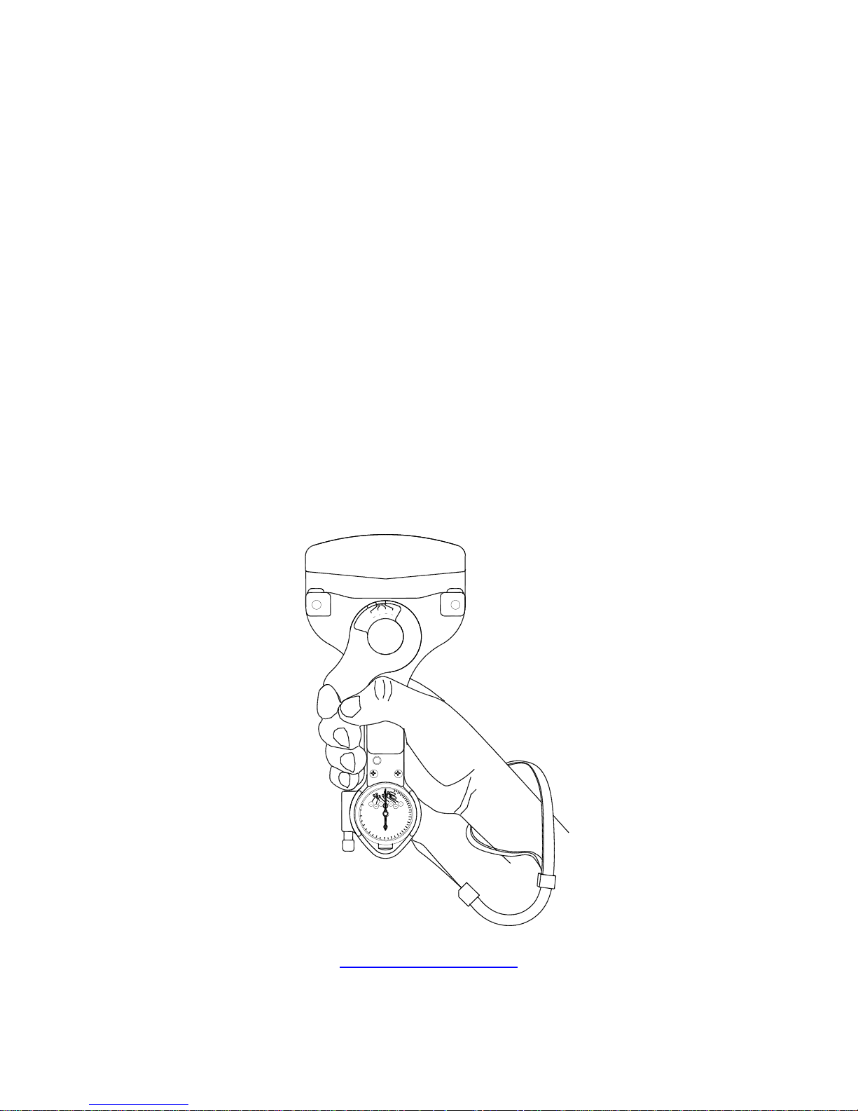
Firm positive 3-point cable grip prevents dislodgement when instrument hanging free on control cable.
The T60 requires no alternate riser for the various size cables. There are no losable parts in the T60.
The instrument is always ready for instant use. An easy to operate, accurate, built-in gage eliminates
guess work as to size of cable to be tested. Simple, comfortable lever grip permits one hand operation
without operator fatigue. In severe cold, service mittens or gloves may be worm without any loss
efficiency of operation.
A simple lock holds dial pointer at exact reading on cables in areas where instrument cannot be seen.
A touch unlocks the pointer preparatory for the next reading. Large, clear numerals make readings
easy and accurate. Bezel is easily turned to the correct zero setting for the proper cable size,
determined by the gage in the handle head. The T60 is a durable precision instrument and is not
damaged by use on cable tensions beyond its range.
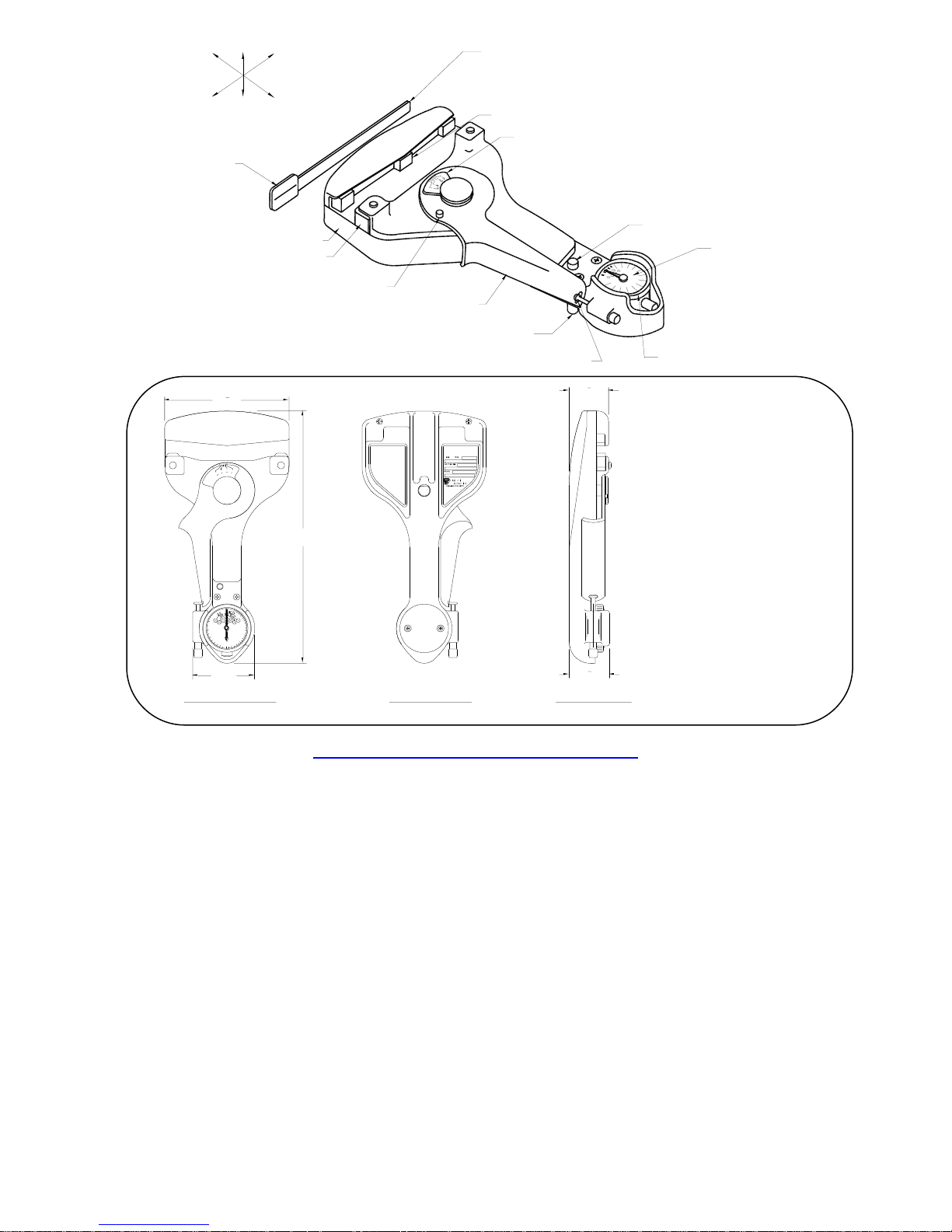
The cable Tensiometer is a hand-held instrument. A jaw is located at the top of instrument. Actual
contact on the cable is made by the riser block and the two sectors located in the jaw. A sliding yoke
slides up the frame of the instrument to provide a measuring force. A dial indicator is located at the
bottom of the instrument to give the actual tension indication. An actuating handle is pivoted at the
center of the instrument and is motivated by a trigger spring within the body of the Tensiometer. A
pointer lock button is situated just above the dial indicator and a handle latch is located on the left side
of the frame to engage the detent notch of the actuating handle. (See figure 1)
one year on new units and (6) six months for repaired units from the invoice date. This warranty is to
ensure the cable Tensiometer is free of defects in materials and workmanship under correct and
normal use. The warranty can be void if the unit has been tampered, altered, dropped or damaged by
an accident.
All returns must have a Return Material Authorization (RMA) number. In order to obtain a RMA, please
contact our Quality Department via email, jorge@optimanufacturing.com, or via fax: (787) 889-2805.
Table 1- Type Identification
SOP-TN-002 Rev. Q
T60 Operations and Service Manual
2
32
CABLE TENSIOMETER
PACIFIC SCIENTIFIC
1
16
3
32
1
8
3
16
7
32
1
4
POUNDS TENSION
10
20
30
40
50
60
70
80
90
100
110
120
130
140
150
200
125+
125-
5
1
4
3
16
1
16
1
8
SECTION II
SPECIAL SERVICE TOOLS
2-1. SPECIAL SERVICE TOOLS - No special tools are required for service or maintenance of the cable
Tensiometer.
SECTION III
PREPARATION FOR USE, STORAGE, and SHIPMENT
3-1. PREPARATION FOR USE - The cable Tensiometer is shipped by the manufacturer in its own
carrying case and is ready for use, for avoid damage on common use, the operator shall be use the
Wrist Band adjustable, see figure 1.1. Each time the cable Tensiometer is used it shall be removed
from the case and the serial number stamped on the nameplate checked against the serial number on
the tab of the calibration bar.
3-2. PERFORMANCE – The Tensiometer shall be capable for use under extreme conditions of heat or
cold without affecting the accuracy of readings, the operating temperature range are -65⁰F to 160⁰F
(-53⁰C to 71⁰C.)
3-3. STORAGE - When the cable Tensiometer is not in use it must be placed in its carrying case. There
are no special instructions or precautions relative to storage.
3-4. SHIPMENT - If the cable Tensiometer is to be shipped, it shall be placed in its carrying case and
packed in such a manner as to avoid damage by common carrier.
SOP-TN-002 Rev. Q
T60 Operations and Service Manual
Figure 1.1- Wrist Band
3
UP
DOWN
BOTTOM
RIGHT
TOP
LEFT
CALIBRATION BAR
RISER
CABLE GAGE
POINTER LOCK BUTTON
PRESET ACTUATING
DIAL FACE
RING
HANDLE LATCH
POINTER UNLOCK
BUTTON
ACTUATING HANDLE
CABLE GAGE STOP PIN
SECTOR
JAW BASE
TAB
32
CABLE TENSIOMETER
PACIFIC SCIENTIFIC
1
16
3
32
1
8
3
16
7
32
1
4
POUNDS TENSION
10
20
30
40
50
60
70
80
90
100
110
120
130
140
150
200
125+
125-
5
1
4
3
16
1
16
1
8
9"
228.6mm
4
1
2
"
114.3mm
2"
50.8mm
INSTRUCTIONS
1- PRESET DIAL TO
CABLE DIA.(NOTE
RANGE LARGER DIA.)
2- CLAMP ON CABLE
SEVERAL PLACES AND
AVERAGE READINGS.
3- TO KEEP DIAL
READING PRESS
BUTTON,
REVERSE
TO RELEASE
CABLE
TENSIOMETER
PATENTS:
2,592,868
D - 157032
MADE IN
U.S.A.
T60040
1
1
2
"
38.1mm
1
1
2
"
38.1mm
FRONT VIEW
Not Scale
REAR VIEW SIDE VIEW
Not Scale Not Scale
T60 TENSIOMETER
Net Weight: 1.58 lb. / .72 kg.
Shipping Weight: 3 lbs. / 1.36 kg.
Figure 1- Cable Tensiometer, Typical
4-1. GENERAL INSTRUCTIONS - Each time the instrument is removed from its case for use check the
serial number on the nameplate to ascertain that it agrees with the serial number on the calibration
Warning: Cable Tensiometers should not be used for adjusting the rig load in a cable system where an automatic
cable tension regulator is installed. All such cable systems should be rigged by adjusting them so that the
pointer on the cable tension regulator scale indicates the correct number based on the surrounding temperature
as indicated on the chart provided by the aircraft Maintenance Manual. The Tensiometer may be used to check
the tension so obtained, but it must be remembered that the actual cable tension will vary from the nominal
depending on the errors in the instrument itself, manufacturing tolerance of springs in the regulators, rate of the
regulator spring, and condition of the control cable. Cable tension readings taken on a regulated control system
therefore can be misleading and can result in damage through improper rigging.
SOP-TN-002 Rev. Q
T60 Operations and Service Manual
bar. Before using the instrument check the calibration by means of the calibration bar. (See paragraph
4-9.)
SECTION IV
OPERATION INSTRUCTIONS
4
 Loading...