


OPR Power Series™
AC to DC POWER SUPPLY SERIES WITH REMOTE MANAGEMENT AND
ALARM SYSTEMS
Model Nos. OPR200-05S / OPR200-05R
Manual
Revision E
May 2010
Optimal Power Supplies LLC
www.optimal-power.com
i

PROPRIETARY DATA
All data in this manual is proprietary and may not be disclosed, duplicated or used for
procurement or manufacturing purposes, without prior written permission by
OPTIMAL POWER SUPPLIES LLC
LIABILITY
DO NOT OPERATE OR SERVICE THE OPR200-05S & OPR200-05R MODELS WITHOUT
READING THIS ENTIRE MANUAL FIRST
Optimal Power Supplies LLC is not responsible for any kinds of damages sustained through the
use of this or any other Optimal Power Supplies LLC products. It is entirely the customer’s
responsibility to take all the necessary precautionary measures when installing this unit.
In the interest of improving internal design, operational function, and/or reliability, Optimal
Power Supplies LLC reserves the right to make changes to the products described in this
document without notice.
WARRANTY
Optimal Power warrants all of its products against defects in materials and workmanship for one
year from date of delivery. We will repair, or replace parts which prove to be defective during
the warranty period provided that:
1. A Return Maintenance Authorization (RMA) is obtained from OPTIMAL POWER at
(251) 209-8088 or
outside of the box the item is shipped in.
2. Shipping charges are pre-paid by customer
Optimal Power does not endorse any other warranty, expressed or implied, and is not liable for
consequential damages. Products that are damaged, opened, or modified do not qualify for a
warranty. The same procedures must be followed for repairs outside the warranty period.
www.optimal-power.com. Please reference your RMA number on the
ii

CHAPTER TITLE PAGE
1 OPR Power Series – Introduction …………………………... 1
1.1 Product Description……………………………………………. 1
1.2 Main Features………………………………………………….. 1
1.3 General OPR Power Series Specifications…………………….. 2
1.4 Typical Safety Rating………………………………………….. 2
2 OPR200-05S / OPR200-05R…………………………………. 3
2.1 OPR200-05S / OPR200-05R Description……………………… 3
2.2 Specifications ………………………………………………….. 3
3 Status Indicators and Back Panel Connections…………….. 5
3.1 Back Panel DC Power Connector……………………………… 5
3.2 Front Panel Status Indicators…………………………………... 5
3.3 Remote Management DB-25 Pin Out for OPR200-05S ….…… 5
3.4 Remote Management DB-25 Pin Out f or OPR200-05R ….…… 5
4 Alarm Systems…………..……………………………………. 6
4.1 Alarm Monitoring System……………………………………… 6
5 Installation and Maintenance………………………………... 7
5.1 Installation……………………………………………………… 7
5.2 Maintenance……………………………………………………. 7
5.3 Warnings………………………………………………………... 8
5.4 Design Block Diagram……………………………..…………... 9
6 Images….………………………………………………………. 10
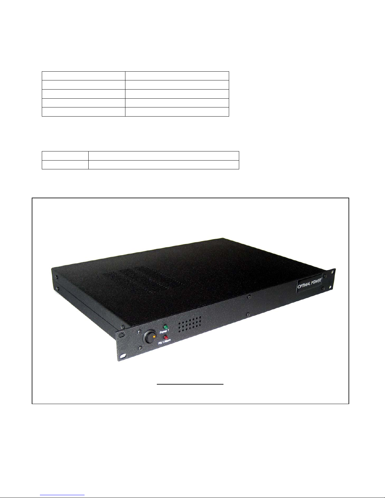
6.1 OPR200-05S (Single Power Supply)…………………………... 10
6.2 OPR200-05R (Redundant Power Supply)……………………... 10
6.3 OPR200-05R (Front View)…………………………………….. 11
6.4 OPR200-05S (Front View)…………………………………….. 11
6.5 OPR200-05S (Rear View)……………………………………… 12
6.6 OPR200-05R (Rear View)……………………………………... 12
6.7 DC Cable Image…………………………………….................... 13
iii

Chapter 1
OPR Power Series - Introduction
1.1 Product Description
OPR Power Series is a unique and a highly reliable power supply series. It can be configured as a
single as well as a fully redundant power supply. OPR Power Series is designed for Universal
AC to DC power supply applications. Because of this feature these power supplies can be used
anywhere in the world. These power supplies are mainly used in the following applications:
• Computer Peripherals and Networking Applications
• Telecommunications and Fiber Optic Network
• Voice, Data and Analog Communications
• Universities and Educational Facilities
• Instrumentation and Electronics
• Utility and Power Industries
• Data Acquisition
• Medical
• Military
OPR Power Series is a reliable, efficient and inexpensive solution for all kind of AC to DC
power supply applications.
1.2 Main Features:
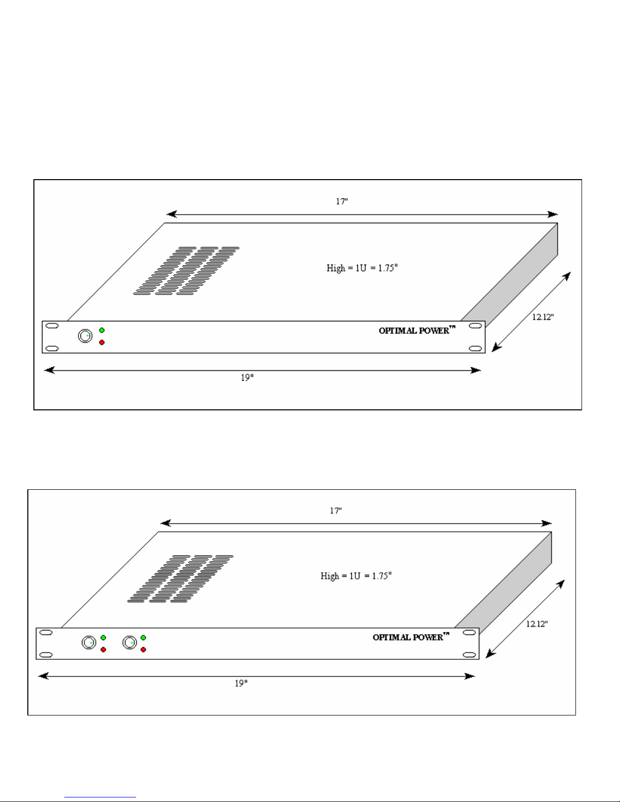
• Compact Rack Mount Size (1.75” H x 19” W x 12.12” D)
• Universal AC (Alternate Current) Input
• Filtered IEC AC Inlet Connectors
• Internal Power Bricks EMI FCC Class B Clearance
• Single and Multiple Output
• Highly Efficient Design
• 1U Low Profile Height
• NO Minimum Load Required
• Remote Management
• Low Voltage Power Supply Alarm
• Cost Effective and Reliable Power Supply Solution
1

1.3 General OPR Power Series Specifications:
Input Voltage………………………………...Universal 90VAC to 264VAC
Input Frequency……………………………...47Hz to 63Hz
Operational Temperature………………….…0°C to 55°C
Storage Temperature………………………..-20°C to 85°C
Cooling………………………………………Cool Air Flow
Overload Protection………………………....Auto-Recovery
Efficiency…………………………………....80-90% Typical
DC OK………………………………………DB25 Interface and Status LEDs
1.4 Typical Safety Rating for Internal Power Modules:
Designed in full compliance with……...……UL60950
CSA 22.2 No. 234
EN60950
EMI………………………………..………...EN55022 “Class B”
EMS…………………………………………EN61000-4-2,-3,-4,-5,-6,-8,-11
Harmonics……………………………..….....EN61000-3-2 Class D
Redundant Power Supply
2

Chapter 2
OPR200-05S / OPR200-05R
2.1 OPR200-05S / OPR200-05R Description:
The Models OPR200-05S and OPR200-05R are 1U rack mountable power supplies designed to
operate in single and redundant power configurations respectively. OPR200-05S has one built-in
universal AC to 5V DC power supply, and OPR200-05R has two built-in universal AC to 5V DC
power supplies with two IEC AC plugs for complete redundancy. OPR200-05S provides up to
200W of power, and OPR200-05R provides up to 400W of redundant power* to the system that
each is attached. Each model has its own AC-INLET (one for OPR200-05S and two for
OPR200-05R for redundancy), ON/OFF switches, and power LEDs (one for OPR200-05S and
two for OPR200-05R). Both models have two built-in alarm circuits with red LEDs for low DC
power monitoring and for remote power management. In addition, models OPR200-05S and
OPR200-05R have Logic Interface for power supply alarm circuit.
2.2 Specifications:
Electrical
Output Voltage +5V DC
Output Ripple Typical 50 mV
Output Current 36A Typical
Output Power 400W for OPR200-05R*
200W for OPR200-05S
Input Voltage Universal 90VAC to 264VAC input (2 AC inlet plugs in
OPR200-05R for complete redundancy)
Input Frequency 47Hz to 63Hz
Input Current 5 Amps max
Remote Management Interface RS485
Note*: 400W is intended only for redundancy; it is not recommended to power a total load
of 400W with the Model OPR200-05R
Typical Safety Ratings for Internal Modules:
Designed in full compliance with UL60950
CSA 22.2 No. 234
EN60950
EMI EN55022 “Class B”
EMS EN61000-4-2,-3,-4,-5,-6,-8,-11
Harmonics EN61000-3-2 Class D
3
Environmental
Overload Protection Auto-recovery
Functional Temperature 0 to 70 °C
Storage Temperature -20 to 85 °C
Over voltage Type Latch off
Efficiency 80-90% Typical
Physical
Dimensions 1U (1.75” H x 19” W x 12.12” D)
Weight Approx. 13.25 lb = 6.01 kg = 212 oz
Single Power Supply
4

Chapter 3
Status Indicators and Back Panel Connections
3.1 Back Panel DC Power Connector
WARNING: Observe
polarity when making
3.2 Front Panel Status Indicators
LED Description (When Lit) Labeled Indicators
Solid Green Power Supply 1 Activated Power 1
Solid Red Power Supply Failure PS 1 Alarm
Solid Green Power Supply 2 Activated Power 2
Solid Red Power Supply Failure PS 2 Alarm
3.3 Remote Management DB25 Pin Out for OPR200-05S
Pin Numbers Description I/O Direction Logic High = 1 Logic Low = 0
Pin # 3 Power Supply Alarm +RS485Output Alarm No Alarm
Pin # 16 Power Supply Alarm –RS485 Output No Alarm Alarm
Pin # 1 Frame Ground Output NA NA
Pin # 7 Signal Ground1 Output NA NA
3.4 Remote Management DB25 Pin Out for OPR200-05R
Pin Numbers Description I/O Direction Logic High = 1 Logic Low = 0
Pin # 3 Power Supply 1 Alarm +RS485Output Alarm No Alarm
Pin # 16 Power Supply 1 Alarm –RS485 Output No Alarm Alarm
Pin # 9 Power Supply 2 Alarm –RS485Output No Alarm Alarm
Pin # 17 Power Supply 2 Alarm +RS485 Output Alarm No Alarm
Pin # 1 Frame Ground Output NA NA
Pin # 7 Signal Ground1 Output NA NA
Note 1: For proper remote management interface functionality. It is importance to connect the signal
ground properly and securely.
connection to the rear of
Model OPR200-05S /
Model OPR200-05R
+ Indicates 5 Volt DC
– Indicates Ground Line
5

Chapter 4
Alarm Systems
4.1 Alarm Monitoring System
The Models OPR200-05S and OPR200-05R have the ability to monitor output DC voltage, and
trigger an alarm when the output DC voltage starts to decrease below the threshold limit. The
power supply models have a threshold limit of 4V DC.
OPR200-05S Alarm Indications
If for some reason the voltages in power supply Model OPR200-05S drop below the threshold
limit (due to overload, for example) the DB25 interface pin 16 will go logic LOW, and pin 3 will
have logic HIGH indicating power supply failure.
DB25 Pin Out Normal Condition Power Supply Failure
Pin 16
(Power Supply Alarm)
Pin 3
(Power Supply Alarm)
OPR200-05R Alarm Indications
If for some reason the voltages of power supply 1 in the Model OPR200-05R drop below the
threshold limit (due to overload, for example) the DB25 interface pins 3 will go logic HIGH, and
pin 16 will have logic LOW indicating power supply 1 failure.
DB25 Pin Out Normal Condition Power Supply Failure
Pin 3
(Power Supply 1 Alarm)
Pin 16
(Power Supply 1 Alarm)
Furthermore, if the voltages of power supply 2 drop below the threshold limit. The interface pin
17 will go logic HIGH, and pin 9 will have logic LOW indicating power supply 2 failure.
DB25 Pin Out Normal Condition Power Supply Failure
Pin 17
(Power Supply 2 Alarm)
Pin 9
(Power Supply 2 Alarm)
Logic High = 1
Logic Low = 0
Logic Low = 0
Logic High = 1
Logic Low = 0
Logic High = 1
Logic Low = 0
Logic High = 1
Logic High = 1
Logic Low = 0
Logic High = 1
Logic Low = 0
6

Chapter 5
R
Installation and Maintenance
5.1 Installation
OPR200-05S and OPR200-05R may be installed in a fixed, semi-fixed and mobile environments
that meet the environmental characteristics specified in Chapter 2. These models are designed to
be mounted in a standard 19” equipment rack utilizing the mounting holes provided on the front
of each unit. It is recommended that at least 1 rack unit (1U = 1.75”) gap be provided above
or below the OPR power supply unit for proper air flow.
Once these power supplies are mounted in the rack, they should be connected to the system (that
only requires 5V DC power) with the DC output connector located at the rear of the OPR unit.
OPR200-05S Setup
Once all the wires are connected properly as described in the above installation paragraph:
(1) Turn "ON" the front panel switch.
(2) The "Power" LEDs, should light up.
Now the system is ready to operate to its required purpose.
OPR200-05R Setup
Once all the wires are connected properly as described in the above installation paragraph:
(1) Turn "ON" the front panel switch for Power supply 1
The "Power 1" green LED, and "PS 2 Alarm" red LED should light up. Indicating Power
supply 1 is "ON" and Power supply 2 is "OFF"
(2) Turn "ON" the front panel switch for Power supply 2
This should clear the "PS 2 Alarm" red LED and cause the "Power 2" green LED to illuminate.
Now the system is ready to operate to its required purpose.
WARNING: Observe polarity when making connection to the rear of model
OPR200-05S / OPR200-05
¾ Next, ensure that the front panel power switch(es) are in “OFF” position.
¾ Connect the AC power cord to the unit by plugging the free end of the power cord into a
standard three prong AC outlet.
¾ Ensure that the AC power plug(s) located at the rear end of the power supply are
connected to a clean and well-grounded Universal AC source.
7

Monitoring AC Input and DC Output
OPR Series models have switches that monitor AC current input and DC current output.
Whenever the “Power” switches are “ON”, the LEDs embedded in the switch should light up.
These indicate good AC input. Similarly the “Power 1” (or “Power1” and “Power2” in redundant
models) LEDs should turn green, indicating good DC output.
Alarm Conditions for Redundant Power Supply
• Power 1 Failure
• AC plug disconnected to Power 1
• Front panel Switch to Power 1 is in “OFF” position
• Power 2 Failure
• AC Plug disconnected to Power 2
• Front panel Switch to Power 2 is in “OFF” position
5.2 Maintenance
The Models OPR200-05S and OPR200-05R should be treated with the sufficient care.
• Do not use abrasives or solvents, as they may mar surfaces
• Do not subject the unit to excessive temperature extremes
• Do not subject the unit to excessive moisture or spilled liquids
• Do not subject the unit to sudden or severe shocks
• Never operate the Model OPR200-05S / OPR200-05R with any of the covers removed
5.3 Warnings
To reduce the risk of fire, electric shock or product damage, DO NOT expose the OPR200-05S /
OPR200-05R unit(s) to direct heat, rain, moisture, dripping or splashing. DO NOT place any
object filled with any kinds of liquids on the unit(s). To prevent damage to LEDs and switches,
DO NOT place the front panel of the unit face down, and/or DO NOT press against the front
panel.
Optimal Power is not responsible for any kinds of damages sustained through the use of
this product.
8
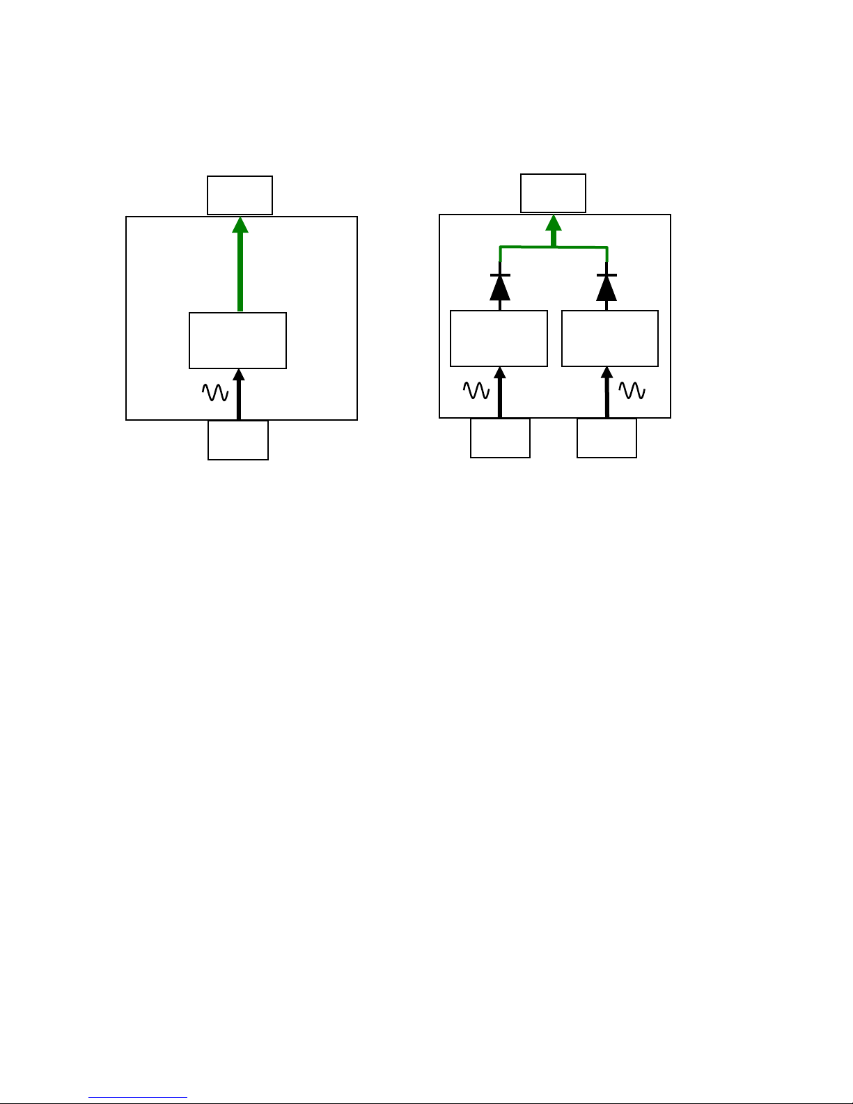
5.4 Design Block Diagram
OPR200-05S
Module 1
DC
OUPUT
Power
AC
INPUT
OPR200-05R
Power
Module 1
AC
INPUT
DC
OUPUT
Power
Module 2
AC
INPUT
9
6.1 OPR200-05S (Single Power Supply)
Chapter 6
Images
6.2 OPR200-05R (Redundant Power Supply)
10

11
”
Power 1
PS 1 Alarm
6.4 OPR200-05S (Front View)
”
Power 1
PS 1 Alarm
Power 2
PS 2 Alarm
6.3 OPR200-05R (Front View)
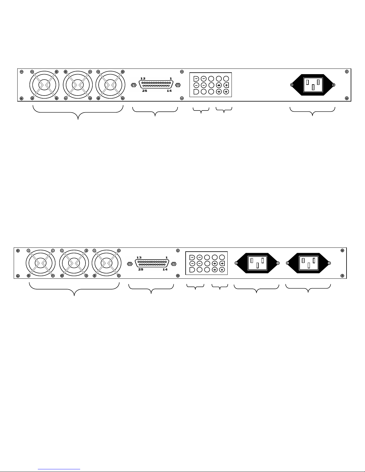
6.5 OPR200-05S (Rear View)
Three Cooling Fans
DB-25 Interface
Remote Management
Pin 1 = Frame Ground
Pin 3 = Power Alarm
Pin 7 = Signal Ground
Pin 16 = Power Alarm
Ground +5V
AC Input Volt
Power Supply
6.6 OPR200-05R (Rear View)
Three Cooling Fans
DB-25 Interface
Remote Management
Pin 1 = Frame Ground
Pin 3 = Power 1 Alarm
Pin 16 = Power 1 Alarm
Pin 9 = Power 2 Alarm
Pin 17 = Power 2 Alarm
Pin 7 = Signal Ground
Ground
+5V
AC Input Volt
Power Supply 2
AC Input Volt
Power Supply 1
12

6.7 DC Cable Image
Important Note* For proper current flow make sure to connect all the specified power
terminals. The DC cable comes with the power supply unit.
Black = Ground Lead = 0V
14 AWG Wire Required
Red = Positive Lead = +5V
*
WARNING: Observe
polarity when making
connection to the rear of
Model OPR200-05S /
Model OPR200-05R
+ Indicates 5 Volt DC
– Indicates Ground Line
13
 Loading...