

Page 1

IVT Optima
600 - 1700
FOR THE USER
User Guide
Art. no: 12313 Version 1.0
Page 2

Page 3

Thank you for choosing a heating installation from
IVT Industrier AB
We hope that our heating installation meets your expectations and gives you many years of energy saving. We want you and
your family to enjoy a good economy at the same time as you actively safeguard the environment. We have taken today’s
demands on heating systems into consideration and believe that your Optima will give you many useful functions in the
future. Your heating installation features an advanced control unit that monitors and controls the temperature in the house
and contributes towards improved overall economy.
IVT is the leading heat pump manufacturer in the nordic countries. More than every second heat pump comes from IVT. We
have worked with solutions to reduce energy consumption on the environment’s terms for more than 30 years. Today we
can present the widest range of heat pumps for effi cient energy saving in all types of housing and properties.
Manual Heat pumps IVT Optima 600 - 1700
IVT Industrier AB, 2007/09
Article number: 12313
Version 1.0
Copyright © 2007. IVT Industrier AB. All rights reserved. IVT reser ves the right to make changes to the product without prior notice.
This manual contains copyright protected information that is the property of IVT Industrier AB. No part of this document may be copied or for warded, electronically or mechanically,
without prior, written permission from IVT Industrier AB. This includes photographing and translation to another language.
Page 4

Table of Contents
Innehåll
FOR THE USER .............................................................................................................. 5
Important information ........................................................................................................................... 5
How a heat pump works ........................................................................................................................ 6
Technology in and around the heat pump ...........................................................................................................................6
Component parts of the heat pump......................................................................................................... 8
IVT Optima 600-1100 ........................................................................................................................................................ 8
Component parts of the heat pump......................................................................................................... 9
IVT Optima 1400-1700 ...................................................................................................................................................... 9
Control unit Rego 800 ......................................................................................................................... 10
Automatic defrosting .........................................................................................................................................................10
The control unit’s operating modes .................................................................................................................................... 11
The control unit’s control method for heating ....................................................................................................................12
Control panel ...................................................................................................................................... 13
Status lamp ......................................................................................................................................................................13
Menu dial .........................................................................................................................................................................14
Power switch (ON/OFF) ..................................................................................................................................................14
Menu display .................................................................................................................................................................... 14
How to use the control panel ............................................................................................................................................. 14
Symbol overview ...............................................................................................................................................................14
Menu levels ........................................................................................................................................ 15
Menu ................................................................................................................................................. 15
Menu overview .................................................................................................................................................................15
Set the heating ..................................................................................................................................................................16
Extra hot water .................................................................................................................................................................16
Temperatures ....................................................................................................................................................................17
Advanced menu .................................................................................................................................. 18
Overview .........................................................................................................................................................................18
Set the heating ..................................................................................................................................................................19
Set the desired room temperature ......................................................................................................................................21
Time limited settings.........................................................................................................................................................21
Heating season .................................................................................................................................................................22
Heating, maximum operating time at hot water requirement ............................................................................................22
Hot water settings .............................................................................................................................................................23
Timers ..............................................................................................................................................................................24
Setting the clock ................................................................................................................................................................24
Alarm log .........................................................................................................................................................................25
Access level .......................................................................................................................................................................25
Return to factory settings...................................................................................................................................................25
Deactivate alarm buzzer ................................................................................................................................................... 25
Program version ...............................................................................................................................................................25
Maintenance ....................................................................................................................................... 26
What to do if a fault occurs .................................................................................................................. 28
Dimmed menu display ......................................................................................................................................................28
Emergency operation ........................................................................................................................................................28
All alarms and warning windows .....................................................................................................................................29
Technical information .......................................................................................................................... 35
Factory settings .................................................................................................................................................................35
Technical information ......................................................................................................................................................36
Sound levels ......................................................................................................................................................................36
Sensor table ...............................................................................................................................................................37
4
Page 5

For the user
Important information
IVT Optima is a family of heat pumps, that extract energy from outdoor air
to produce water based heating and, if required, hot water for your house.
The family consists of Optima 600, Optima 900, Optima 1100, Optima 1400
and Optima 1700, which cover different levels of output requirement.
Optima can be connected to an existing electric/oil-fi red boiler or to an
electric cassette, which provides a complete heating installation. In this
case, a hot water heater is often connected so that the hot water is also
managed by the installation. The electric/oil-fi red boiler or electric cassette
works as additional heat if the heat pump cannot manage all heating itself,
e.g. if the outdoor temperature is too low.
The heating installation is controlled by a control unit, which is in a
separate control cabinet. The control unit controls and monitors the total
system using different settings for heating, hot water and other operations.
The settings are made by the installer and the user via a control panel.
Important information for the user
Note
It is important as the user that you
read through this guide.
Under no circumstances may you
make settings that are designed for
the installer. This can cause serious
malfunction of the heat pump.
Optima 600-1100 can also be connected to electric boiler IVT 290 A/W
to provide a complete installation for both heating and hot water as the
electric boiler contains a hot water heater. The electric boiler functions as
additional heat when necessary.
In this case the control unit is located in the electric boiler.
When the heat pump has been installed and started there are a number of
points you should check regularly. This may concern an alarm triggering
or performing basic maintenance actions. Initially you should perform
these actions on your own. This manual describes each step in detail. If the
problem remains you should contact your dealer.
This guide contains a description of Optima, what it consists of, maintenance, settings etc.
For information regarding use of the existing electric/oil-fi red boiler, see
the boiler’s documentation.
Operating instructions for IVT 290 A/W are described in its own guide.
Also read this if you have Optima 600-1100 with 290 A/W.
Note
Only a trained and qualiÞ ed technician may carry out repairs to this machine. Incorrect repairs
can lead to serious risks to the user, and a reduction in savings.
Visits from an authorised Service representative to make corrections or adjustments after such a
repair, cannot in such cases be carried out free of charge, not even during the warranty period.
5
Page 6

How a heat pump works
How a heat pump works
The heat pump collects heat from the outdoor air
The Optima heat pump has been manufactured for easy and reliable use as
well as to provide your house with inexpensive and environment friendly
heating. The easiest way to describe how a heat pump works is to say it
works like a refrigerator, however, the other way round. In a refrigerator
heat is moved from the inside to the outside. In a heat pump the heat, in
the outdoor air, is moved into the house. The heat pump is placed on the
outside of your house. The heat that is in the air, even at temperatures
below zero, is converted by the compressor, heat exchanger and condenser
into hot water, which heats your house.
The heat pump can also produce domestic hot water. However, this requires
a hot water heater to be connected. Electric boiler 290 A/W contains a
hot water tank, which means that there is always hot water in the system
(applies to Optima 600-1100 with 290 A/W). In this case, when the electric
cassette or mixed additional heat, e.g. electric/oil-fi red boiler is used, an
external hot water heater can be connected.
The heat pump requires additional energy, e.g. at low outdoor temperatures. This is obtained from the electric cassette, existing electric/oil-fi red
boiler or from 290 A/W.
Electric boiler 290 A/W is available in two versions, 9 kW or 13.5 kW.
When Optima is used together with the electric cassette, the unit can be
supplied with a power guard (option). The task of the power guard is to
temporarily disconnect the electric additional heat when using other power
demanding appliances so that the main fuse does not blow.
The power guard can also be used for Optima 600-1100 with 290 A/W.
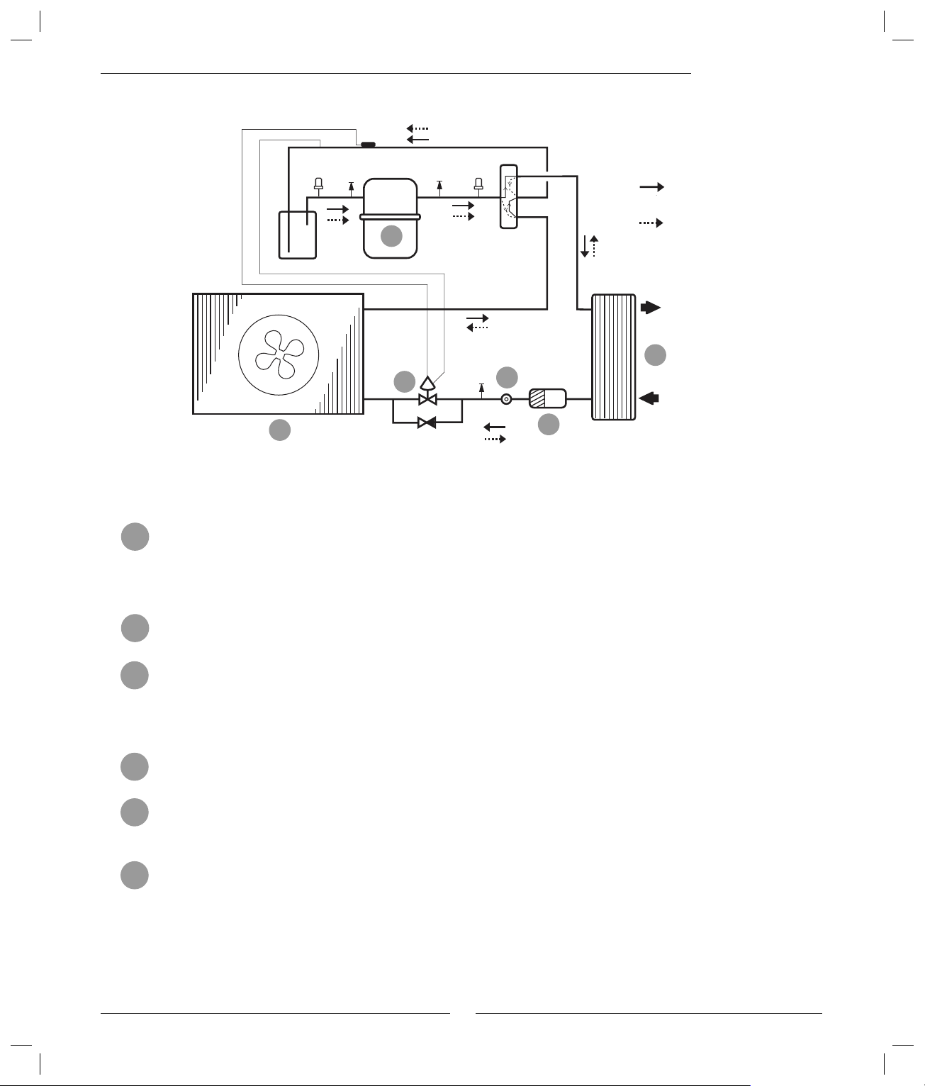
Technology in and around the heat pump
The heat pump consists of four main parts:
1. Evaporator
Evaporates the refrigerant to gas and at the same time transfers the
heat from the air to the refrigerant circuit.
2. Condenser
Condenses the gas to fluid again and releases the heat to the heating
system.
3. Expansion valve
Lowers the pressure of the refrigerant.
4. Compressor
Increases the pressure of the refrigerant.
These four main parts are linked in two closed circuits. A refrigerant
circulates in the heat pump, which in some parts of the circuit is in a liquid
state and in other parts in a gas state. Read more about the properties of the
refrigerant in the sidebar to the right.
Note
Boiling point in relation to the
pressure
The boiling point of different liquids
varies with pressure, the higher the
pressure, the higher the boiling point.
For example, water boils at +100ºC at
normal pressure. Double the pressure
and water boils at +120ºC. Half the
pressure and water then boils at +80ºC.
The refrigerant in the heat pump acts in
the same way, the boiling point changes
when the pressure changes. However,
the boiling point of the refrigerant
is as low as approximately -40ºC at
atmospheric pressure. Consequently,
it is also suitable for low heat source
temperatures.
See the detailed description of the technologies used in the heat pump on
the next page.
6
Page 7
Pressure
switch
low
Suction accumulator
Bulb
Service
connection
How a heat pump works
Service
connection
2
Pressure
switch
high
4-way valve
Refrigerant fl ow in heating
mode.
Refrigerant fl ow in defrost
mode.
Heat transfer fl uid out.
Service
connec-
6
1
Non-return
tion
valve
5
4
3
Heat transfer fl uid in.
The route of the refrigerant through the heat pump in heating mode
The refrigerant meets the outdoor air in the evaporator (heat exchanger). The air is drawn through the evapora-
1
tor by a fan located on top of the heat pump. The refrigerant, which was previously in a liquid state, will evaporate
in this process. The pressure is low and heat is required. Heat is taken from the outdoor air. A sensor in the
expansion valve (6) ensures the evaporator utilises as much of the "free energy" as possible before the refrigerant
(in a gas state) is led into the compressor.
The compressor increases the pressure of the refrigerant. The temperature of the vapour reaches approximately
2
+100ºC. The warm gas is then led into the condenser.
The condenser is the heat pump’s heat emitting part. In the condenser, which is a fully soldered heat exchanger
3
in stainless steel, the refrigerant (gas state) meets the water from the heating system (radiators and fl oor coils).
When the warm gas is cooled by the circulating heating water, it changes into a liquid state (condenses). Energy
is emitted in this process to the heating system or the hot water. After the condenser, the refrigerant, which is
now in liquid form, continues through a drying fi lter.
The drying fi lter is used to collect any moisture in the system. After the fi lter, the refrigerant passes through a
4
sight glass.
The sight glass is used to check the level in the system. There should be no bubbles in the sight glass during
5
normal operations. However, there might be bubbles when the heat pump is started and stopped or during
defrosting. After the sight glass, the refrigerant continues on to an expansion valve.
The refrigerant pressure is lowered in the expansion valve. This also causes the temperature to drop. When the
6
refrigerant has left the valve and passes the evaporator it changes to vapour again. This completes the refrigerant
circuit. The expansion valve is equipped with a sensor (bulb) just before the compressor. The sensor controls the
amount of fl uid entering the evaporator.
7
Page 8
Component parts of the heat pump
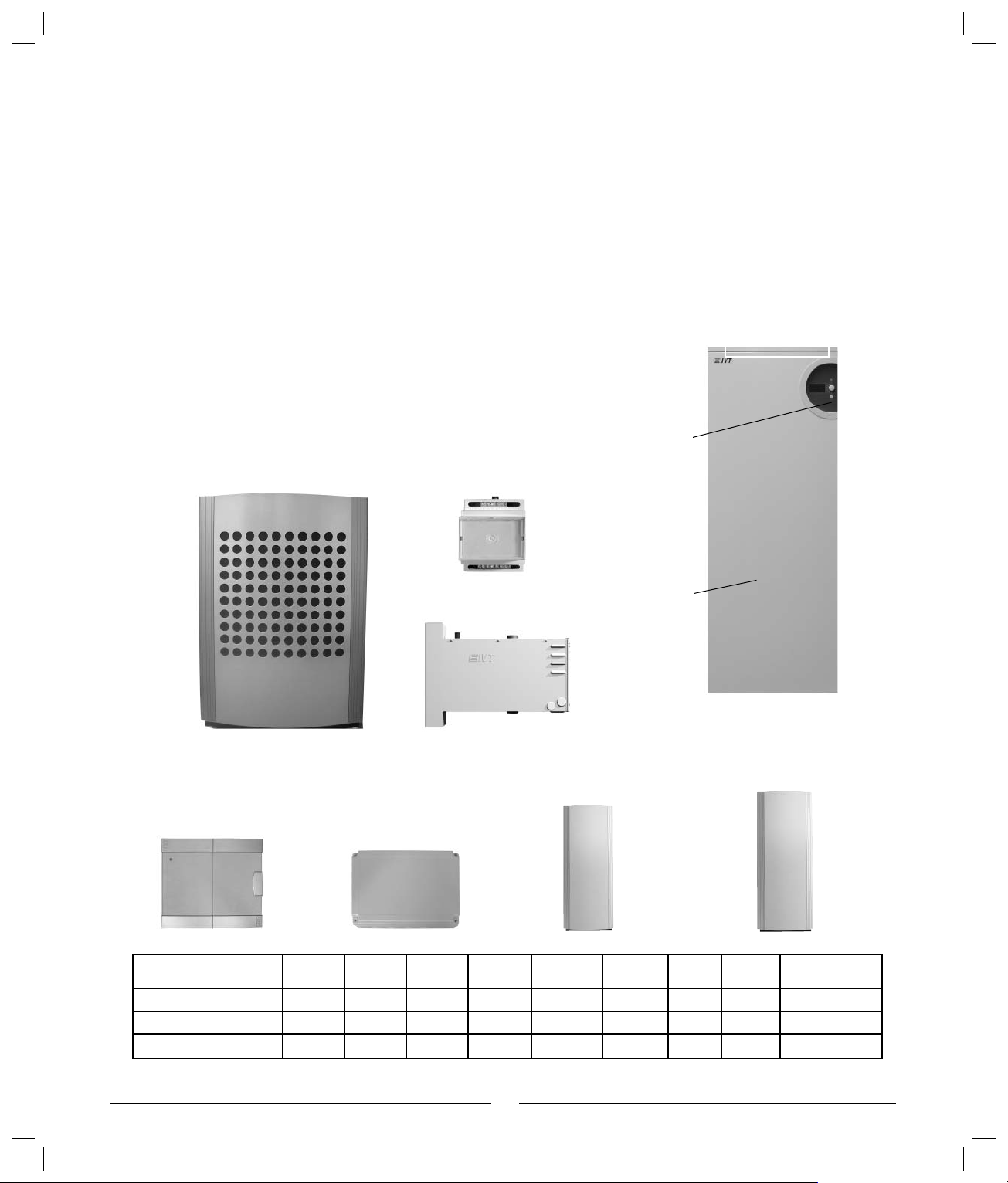
Component parts of the heat pump
IVT Optima 600-1100
When the heat pump is combined with 290 A/W, the control unit is integrated
in 290 A/W, which also includes a hot water heater.
The heat pump is installed outside, the electric boiler and any power guard are
installed indoors.
When the heat pump is combined with electric cassette or existing electric/oilfi red boiler, a control cabinet is included. This is located indoors, normally in
the same room as the electric cassette or electric/oil-fi red boiler. The control
unit is included in the control cabinet. The electric cassette or the optional
unit for electric/oil-fi red boiler is also included and located indoors. Hot
water heater is available as an accessory. This must be equipped with electric
element if electric/oil-fi red boiler is used.
A power guard is available as accessory when electric cassette or 290 A/W is
used.
290 A/W
Control
panel
Optima 600-1100
Rego 800
control cabinet
Power guard, option
Electric cassette, option
Rego 800 option for
Electric/oil-fi red boiler
Hot water
heater
Hot water heater
200/90, accessory
Hot water heater 300/160
with or without electric
element, accessory
Operating mode 600-1100 290 A/W Control
Optima with 290 A/W
Optima with mixed additional heat
Optima with electric cassette
•• •
•• • •
••• •••
cabinet
Electric
cassette
8
Electric/oil-
fi red boiler
Power
guard
200/90 300/160 300/160 with
electric element
Page 9
Component parts of the heat pump
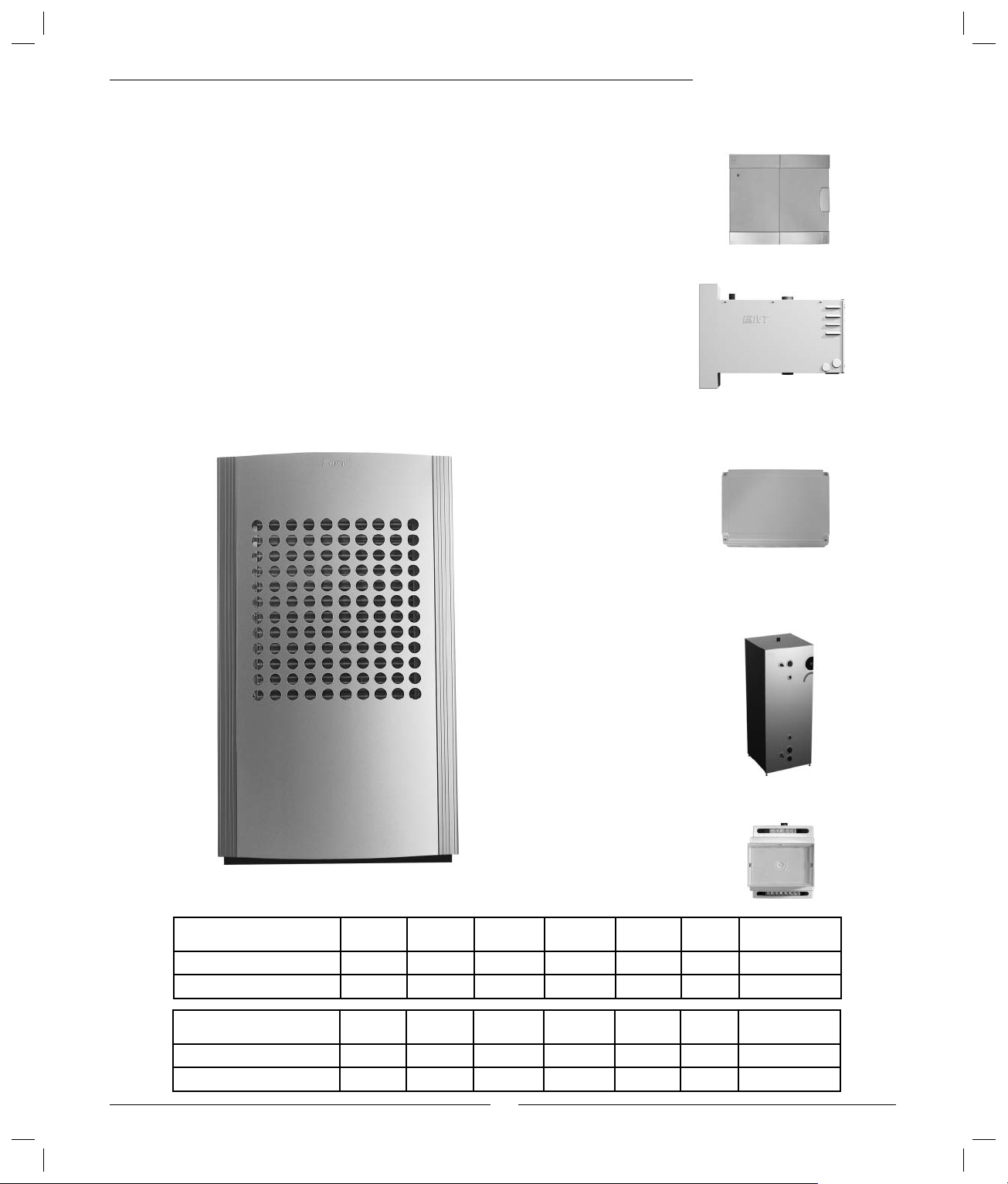
Component parts of the heat pump
IVT Optima 1400-1700
When the heat pump is combined with electric cassette or existing electric
/oil-fi red boiler, a control cabinet is included. This is located indoors, normally
in the same room as the electric cassette or electric/oil-fi red boiler. The control
unit is included in the control cabinet. The electric cassette or optional unit for
electric/oil-fi red boiler is also included and located indoors. Hot water heater
is available as an accessory. This must be equipped with electric element if
electric/oil-fi red boiler is used.
A power guard is available as accessory when electric cassette is used.
Optima 1400-1700
Rego 800 control cabinet
Electric cassette, option
Rego 800 option for
Electric/oil-fi red boiler
Coil tank 302/502 with or
without electric element,
accessory
Operating mode 1400 Control
Optima with mixed additional heat
Optima with electric cassette
Operating mode 1700 Control
Optima with mixed additional heat
Optima with electric cassette
•• • •
•• • •• •
•• • •
•• • •• •
cabinet
cabinet
Electric
cassette
Electric
cassette
9
Electric/oil-
fi red boiler
Electric/oilfi red boiler
Power
guard
Power
guard
Power guard, option
302 302 with electric
502 502 with electric
element
element
Page 10
Control unit
Control unit Rego 800
The control unit makes sure the heat pump gives the best energy savings
and that it runs for many years. The control unit controls and monitors the
heating and hot water supply in your house. The monitoring function is especially important, it shuts down the heat pump in the event of operational
disturbances so that no critical parts are damaged.
Additional heat gives more output
Additional heating is required when the heat pump is unable to meet the
heating requirements or when it has stopped due to an outdoor temperature
that is too low. The additional heat is provided by an electric cassette,
existing electric/oil-fi red boiler or electric boiler 290 A/W (Optima 600-
1100). Note that when the heat pump is running, the additional heat source
only supplies the power that the heat pump cannot produce. When the heat
pump is once more able to meet the heating demand, the additional heat is
automatically switched off.
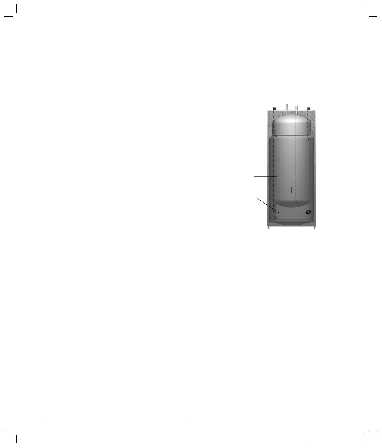
Hot water is given priority over heating water
In a house with water based heating a difference is made between heating
water and hot water. The heating water is for radiators and underfl oor coils
and hot water is for showers and taps.
When electric boiler 290 A/W is included, hot water is heated in the electric
boiler’s hot water heater. When the electric cassette or existing electric/oilfi red boiler is included, an external hot water heater can be connected.
In both cases, there must be a sensor, which detects the temperature of
the hot water. The heating water passes through the hot water cylinder’s
outer shell and heats up the hot water heater’s inner tank. The control unit
makes sure the heating of hot water is given priority over the heating of the
heating water.
Hot water
Heating
water
Automatic defrosting
Ice may form on the evaporator at outdoor temperatures below +10ºC.
When ice forms to an extent that it obstructs the air fl ow through the evaporator automatic defrosting starts. Defrosting is controlled by a four-way
valve. The valve reverses the fl ow of the refrigerant in the circuit so that the
hot gas melts the ice on the evaporator fi ns. See Refrigerant fl ow in defrost
mode in the fi gure under the heading How a heat pump works.
There is also a fan defrost function, which means that hot air blows upwards
through the fan to prevent it freezing solid.
10
Page 11

The control unit’s operating modes
When a heat pump is installed, it must be set-up for a specifi c operating
mode. An operating mode relates to the heat pump’s working situation
which is dependent on the prevailing conditions, for example, whether an
electric or oil-fi red boiler is to be connected.
It is the task of the installer to adjust the heat pump with the correct
settings for the relevant operating mode and other conditions.
Heat pump with electric cassette
When the heat pump is used with one (or two) electric cassettes, the control
unit in the control cabinet sets itself for this operation. This means that the
heat pump works with additional heat from the electric cassette and that hot
water is produced in an external hot water heater, if connected. A sensor
located on the outside of the house sends information about the outdoor
temperature to the control unit. The control unit controls heating and hot
water production based on the read off current values and the set values.
Heat pump with mixed additional heat, e.g. an
existing electric/oil-fi red boiler.
When the heat pump is used with an existing electric/oil-fi red boiler, the
control unit in the control cabinet sets itself for this operation. This means
that the heat pump works with additional heat from the electric/oil-fi red
boiler and that hot water is produced in an external hot water heater, if
connected. A sensor located on the outside of the house sends information
about the outdoor temperature to the control unit. The control unit controls
heating and hot water production based on the read off current values and
the set values.
Control unit
Heat pump with electric boiler 290 A/W
(Optima 600-1100)
When the heat pump is used with 290 A/W, the control unit sets itself for
this operation. This means that the heat pump operates with additional heat
from the electric boiler and that the hot water is produced in the electric
boiler’s hot water heater. A sensor located on the outside of the house
sends information about the outdoor temperature to the control unit. The
control unit controls heating and hot water production based on the read off
current values and the set values.
11
Page 12

Control unit
The control unit’s control method for heating
The control unit controls heating production based on an outdoor sensor or
an outdoor sensor in combination with a room sensor.
Control with an outdoor sensor
Control with an outdoor sensor is the most common method used by the
control unit to control the heat pump. A sensor is mounted on the external
wall of the house (the wall that is the coldest and subjected to the least
amount of sun). The sensor sends signals to the control unit in the heat
pump. Control with an outdoor sensor means that the heat pump automatically regulates the heating in the house depending on the outdoor temperature.
You determine the temperature of the heating system, in relation to the
outdoor temperature, with the help of a number of settings (curves) stored
in the control unit. The curve indicates the fl ow temperature for heating
water in relation to the outdoor temperature. Selecting a lower curve gives a
lower fl ow temperature and therefore higher energy savings.
Control with an outdoor sensor and a room sensor
Control with an outdoor sensor supplemented with a room sensor
(accessory) means that you also place a sensor in a central position inside
the house. This is connected to the heat pump and provides the control unit
with information about the current room temperature. The signal affects
the heat curve’s fl ow temperature. For example, it falls when the room
sensor shows a higher temperature than the one set.
A room sensor is used when factors other than the outdoor temperature
infl uence the indoor temperature of the house. For example, this can be
when a stove or fan-assisted radiator is used in the house, or if the house is
sensitive to the wind or exposed to direct sunlight.
Note
It is only the room where the room
sensor is located that can infl uence
regulation of the temperature.
12
Page 13

Control panel
All settings are made in the control panel and any alarms can be
viewed in the panel. The control unit is controlled via the panel in
accordance with your requirements.
When the heat pump is combined with 290 A/W, the control panel
and control unit are in 290 A/W.
When the heat pump is installed with electric cassette or electric/oilfi red boiler, the control panel and control unit are in the separate
control cabinet.
Control panel
Control cabinet290 A/W
Menu dial
Status lamp
Menu
window
Menu dial
Switch
(ON/OFF)
Status lamp
The control cabinet’s status lamp is on the outside of the unit.
Lamp lights green: Switch ON/OFF in ON position.
Lamp fl ashes green: Switch ON/OFF in OFF position.
Lamp not lit: No voltage to control unit.
Lamp fl ashes red: An alarm has been triggered and the alarm has not
been acknowledged.
See section What to do if a fault occurs.
Lamp lights red: A fault has occurred. Contact the installer.
See section What to do if a fault occurs.
Emergency
operation
Menu display
13
Page 14

Control panel
Menu dial
The menu dial is used to navigate between the menus and to confi rm your
selection. You also determine the values of different settings by using
the dial. If, for example, you turn the menu dial clockwise the value will
increase. Always press the menu dial to confi rm your selection.
Power switch (ON/OFF)
You start and stop the heating installation using the power switch button.
Menu display
The menu display gives you information and several settings options.
You can:
Select different temperatures for heating and hot water (if hot water
heater is fitted).
Select time control settings (different heat at different times).
See alarm causes and receive corrective instructions.
How to use the control panel
Navigate the menus using the menu dial. Turn the menu dial clockwise to
move down through the menus. Turn the menu dial anti-clockwise to move
up through the menus. When the desired row is marked, press the menu
dial to confi rm your selection.
Certain functions have longer names than available space in the menu
window. In such cases, the row switches to show the different parts of
the text. Example: Room temperature setting: First, Room temperature... is
displayed, this then goes out and ...setting is displayed for a few seconds,
whereupon Room temperature... is displayed again. At the top and bottom
of each sub menu there are back arrows that take you back to the previous
menu. Press the menu dial when these are marked.
Symbol overview
Symbols for different functions and components that are
in operation are displayed in the lower part of the menu
window.
Compressor
Hot water mode
Back arrows
Heating mode
Hot water peak
Fan
Extra hot water
Timer Control
Holiday operation
Additional heat
14
Power guard
Alarm
Page 15

Menu levels
The menus are divided into different levels for different purposes.
Menu Customer level, here you will fi nd the most common functions.
Advanced menu Customer level, here you will fi nd further functions.
Installer/Service Installer/Service level, relevent settings are made here by the installer/ser vice technician.
As a user of the heating installation, you only see what is available in the two customer levels.
Menu
The initial menu in the control unit is called Menu. Here you will fi nd the
functions most frequently used and the ones you have the most benefi t of.
The functions available in your heating installation are shown in Menu. For
example, either Temperature increase/decrease or Room temperature setting
(if you have a room sensor) is shown. Extra hot water is only displayed if
you have a hot water heater connected.
Menu
Menu overview
=
The menu display is only shown in
combination with an extra sensor or in a
specifi c operating mode.
15
Page 16

Menu
Set the heating
There are two ways to set the heating level depending on whether the
heating installation is supplemented with a room sensor or not.
Setting the heating, room sensor not installed:
Select Temperature increase/decrease in the menu. Select one of the
following alternatives:
++ Much warmer (approximately +1ºC)
+ Warmer (approximately +0.5ºC)
= Unchanged temperature
− Colder (approximately 0.5ºC)
−− Much colder (approximately -1ºC)
Then press the menu dial. Select Save to confi rm your selection.
Setting the heating, room sensor installed:
1. Select Room temperature setting in the menu.
2. Enter the desired room temperature. Min = +10ºC, max = +35ºC.
3. Select Save to save the change or Cancel to return without saving.
Note
You should wait at least twenty-four
hours when increasing or decreasing the heating before making a new
adjustment.
Under Advanced menu you can change how much the room sensor is to
affect the heating system, see Set the desired room temperature.
Extra hot water
When a hot water heater is installed, you can temporarily increase the temperature of the hot water to approximately 65ºC, via the function Extra hot
water. A higher water temperature gives more hot water when, for example,
several people wish to shower. The heat pump uses the additional heat to
increase the temperature to 65ºC.
In Extra hot water you choose how long the function should be active. This
is what to do:
Select Extra hot water in the menu. Turn the dial clockwise to increase the
number of hours and reduce by turning it anti-clockwise.
Select Save to save the setting or Cancel to return without saving.
To fi nd out how much time remains until the Extra hot water function
switches off, go to Timers under Advanced menu. You can also change the
number of hours during an ongoing Extra hot water function.
16
Page 17

Temperatures
There are several different temperature sensors connected to the heating
installation. Each sensor plays an important par t in the heat pump's daily
operations. The current temperatures for the sensors which are most
important for controlling heating and hot water production are given under
Temperatures.
Select Temperatures in the menu.
The menu display shows the current temperatures for the following
temperature sensors:
Flow sensor (T1)
Shows the temperature in the heating unit’s flow temperature, i.e. the
temperature of the heating water that is fed into the heating system.
In the example, the sensor shows 32ºC.
Outdoor sensor (T2)
Shows the outdoor temperature. Some deviation may occur due to
thermal radiation from the house to the installed outdoor sensor.
In the example, the sensor shows -2ºC.
Menu
Hot water sensor (T3)
Only shown when there is a hot water heater installed. The sensor
shows the temperature in the lower section of the outer container in
the hot water heater. The temperature is approximately 5ºC lower than
the temperature of the hot water inside the inner container.
In the example, the sensor shows 50ºC.
Room sensor (T5)
Only shown if a room sensor is installed. The menu shows the
temperature in the room where the sensor is installed.
In the example, the sensor shows 20ºC.
Note
The values for V and H are also displayed in the window. In the example,
V is 20.0ºC and H 55.2ºC. V and H are
described under Set the heating.
17
Page 18

Advanced menu
Advanced menu
The initial menu in the control unit is called Menu. In this menu you will
fi nd the functions most frequently used and the ones you have the most
benefi t of. In addition, there are extra functions that can be used to affect
your heating installation. These are provided in the Advanced menu. To the
right you will fi nd all functions under Advanced menu.
To access Advanced menu press the menu dial and keep it pressed in for at
least 5 seconds.
Overview
Advanced menu
•Temperature
•Hot water
•Timers
•Setting the clock
•Alarm
•Access level
•Return to factor y settings
•Deactivate alarm buzzer
•Program version
=
The menu display is only shown in
combination with an extra sensor
or in a specifi c operating mode.
18
Page 19

Set the heating
The simplest way to set the heating has been described earlier under
the heading Menu. There is a more controlled way of setting the
heating. However, before we explain how to do this it is important to
understand the relation between the outdoor temperature and fl ow
temperature . The easiest way to explain the relation is by a Heat curve.
Heat curve
You use the heat curve to help set the desired indoor temperature. The
heat pump is controlled by the outdoor temperature. When the weather
becomes colder the heat pump ensures more heating is produced
automatically.
Advanced menu
Flow temperature (ºC)
The following example shows that an outdoor temperature of –2.5ºC
gives a fl ow temperature of 35ºC at the current heat curve.
Flow temperature:
The fl ow temperature is the temperature of the water that is fed into the
heating system.
Outdoor temperature:
The outdoor temperature determines how much heating the heat pump
should produce. The outdoor sensor sends signals to the control unit,
which then affects the heat pump.
Curve slope:
By offsetting the left (V) and /right (H) end points, the slope of the heat
curve can be altered. Use the left end point to adjust the fl ow temperature at high outdoor temperatures and the right end point to adjust the
fl ow temperature at low temperatures.
Adjusting a single value:
You can also adjust a single value on the curve up or down every fi fth
outdoor degree. You can, for example, create an increase in the heat
curve at 0ºC.
Curve slope
Outdoor temperature (ºC)
Note
On delivery of the heat pump, the
curve slope is set at V=20, H=55.2.
Curve slope:
V=22, H=30: Normal basic setting for
underfl oor heating in concrete.
V=22, H=35: Normal basic setting for
underfl oor heating in wooden joists.
V=20, H=55: Normal basic setting for
radiators.
V=20, H>65: Abnormal high setting.
19
Page 20

Advanced menu
Set the heat curve
1. Select Heat curve in the menu Heating system temperature. The current
curve is shown here. The value 32.8 is the fl ow temperature at 0ºC.
2. Start by fi nding the value you wish to change. It can be V, H or some
other value. To fi nd the correct value, turn the dial clockwise or
anti-clockwise. At the top of the display, various outdoor temperatures
with corresponding fl ow values on the curve are shown, at the bottom,
a dash can be seen that shows the position on the outdoor temperature
axis. Continue turning the dial and you will eventually fi nd the H value.
Continue turning the dial even when you see a back arrow.
3. The most common adjustment is to increase the H value slightly to
obtain more heating in cold weather. In the display you will see that the
H value has been located and then marked by pressing the dial. The H
value can now be changed by turning the dial. When you are happy with
the H value, press the dial and select Save.
4. It may also be necessary to change a specifi c value on the curve, e.g. to
increase the heating at temperatures around 0ºC. Turn the dial to fi nd
the value at 0ºC and press the dial to mark the value.
In the example to the right, the value at 0ºC has been changed to 36.8ºC,
i.e. the fl ow temperature has been increased by four degrees. The dial
has been pressed and Save has been marked. The changed curve is
now saved by pressing the dial.
Recommended values: Increase by 4ºC at outdoor temperature of 0ºC
and by 2ºC at outdoor temperature of +5ºC.
5. To exit the Heat curve function turn the dial until you see a back arrow.
Press the dial.
Note
You should wait at least twenty-four
hours when increasing or decreasing the heating before making a new
adjustment. Only change one value at
a time until you are happy with your
temperature settings.
20
Page 21

Hysteresis
Hysteresis settings can be made under Heating system temperature. The
hysteresis determines when the heat pump (compressor) is to start/stop in
relation to the heat curve’s value. The compressor continues slightly longer
than according to the curve and starts again when the fl ow temperature has
dropped somewhat below the value of the curve. In this way, the heat pump
is prevented from starting and stopping continuously.
There is usually no reason to adjust the hysteresis factory settings or those
having been set by the installer.
Set the desired room temperature
If you have a room sensor connected to the heat pump you can set the
required temperature in the room from the Room sensor settings menu. This
is carried out in the same way as in Menu (initial menu).
You can also set how much the sensor is to affect the heating system by
selecting Room sensor infl uence and adjusting the Change factor. Min = 0,
max = 10. A higher factor gives a greater infl uence from the room sensor.
After a heat lowering period, e.g. time control or holiday, the room sensor
infl uence is blocked for a set time, factory setting is 4 hours. Min = 0 and
max = 24 hours. The function Blocking time is under Room sensor infl uence
and means that the heat pump is given time to increase the fl ow temperature more slowly than if the room sensor is allowed to infl uence.
Advanced menu
Time limited settings
Time control
The Time control heating function can be used to lower or increase the
temperature on different week days at chosen times.
1. Select Time control heating in the menu Time limited settings under
Temperature.
2. Select Day and time.
3. Enter the week day and the time at which time control is to occur.
Select On.
4. Select Save to save the change or Cancel to return without saving.
5. Select Change in temperature and set the desired value.
Min = -20ºC, max = +20ºC.
6. Select Save to save the change or Cancel to return without saving.
To remove a time control setting, fi nd the desired setting and select Of f.
Note
Time control is not recommended
in normal conditions as it can affect
consumption negatively.
21
Page 22

Advanced menu
Holiday
Using the Holiday function, you can reduce (or increase) the temperature
between two set dates.
1. Select Holiday in the menu Time limited settings under Temperature.
2. Select the start date and end date according to year-month-day.
3. Select Save to save the change or Cancel to return without saving.
4. Select Change in temperature and set the desired value. Min = -20ºC,
max = +20ºC.
5. Select Save to save the change or Cancel to return without saving.
To cancel the function and remove a time setting, go to Holiday and change
the end date.
Heating season
The Heating season function means that the heat pump only produces
heating water when the outdoor temperature drops below a preset temperature. The preset temperature, Heating season limit, can be adjusted (factory
setting 18ºC, min = 10ºC, max = 35ºC), as can the delay before activation
(factory setting 4 hours, min = 0, max = 24 hours). The delay means that
the heat pump does not need to switch off and on as often when the outdoor
temperature is close to the limit value.
By increasing the value to above 35ºC the heat pump is set to continuous
heating season mode.
There is also an adjustable Direct start limit (factory setting 10ºC,
min = 5ºC, max = 17ºC) that means that the delay is ignored. Heating production starts immediately when the temperature drops below the set value.
Heating, maximum operating time at hot
water requirement
This function is provided to satisfy hot water requirement during heat production, when a hot water heater is fi tted. The factory setting is 20 minutes,
min = 0 and max = 60 minutes.
22
Note
If base heat is required, e.g. in cellars,
it may be suitable to increase the
Heating season limit value.
Page 23

Hot water settings
The menus for hot water settings are only displayed when a hot water
heater is installed.
Extra hot water
You can obtain extra hot water by temporarily increasing the temperature
of the water in the hot water cylinder. A higher water temperature gives
more hot water when, for example, several people wish to shower. The heat
pump uses additional heat to increase the temperature to the desired value,
see point 5. The function Extra hot water (number of hours) is also available
under Menu.
This is what to do:
1. Select Hot water in the advanced menu.
2. Select Extra hot water.
3. Set the number of hours that the function is to be active.
4. Select Save to save the change or Cancel to return without saving.
Advanced menu
Note
When the set time has elapsed you
must repeat the setting to get extra hot
water again. You can also increase the
number of hours during an ongoing
Extra hot water period.
5. Set the desired Stop temperature.
6. Select Save to save the change or Cancel to return without saving.
Read off the remaining time of Extra hot water by going toTimers.
Hot water peak
Recurring increase in the hot water temperature
The Hot water peak menu is used to set the interval for a recurring increase
in the hot water temperature. If, for example, you set the value seven days,
the temperature is increased once a week to approximately 65ºC. You can
also specify Start time for when the temperature increase is to start, factory
setting is 03:00.
Time control hot water
The Time control hot water function means that you can choose to completely disable hot water heating to save energy. This is primarily effective
when peak tariffs are charged. This is done in the same way as other heat
pump time controls.
Note
Time control hot water can impair
hot water production.
23
Page 24

Advanced menu
Timers
There are a number of timers in the control unit. The statuses for these are
shown in the menu Timers. You can only view the timers that are running,
i.e. are counting down. Most timers are only of interest to installers and
service technicians.
Extra hot water
Displays the remaining time for requested extra hot water.
Additional heat start
Displays the countdown of the timer for additional heat delay.
Mixing valve control delay
Displays the time that the mixing valve function is delayed after the additional heat timer has counted down. Does not apply to electric cassette.
Alarm mode delay
Displays the remaining time until the additional heat is activated when an
alarm is triggered.
Compressor start
Displays the remaining time of compressor start delay.
Delay before defrost
Displays the remaining time before defrost is permitted.
Heating, maximum operating time at hot water requirement
Displays the remaining time before the maximum time in heating mode is
reached if there is a simultaneous hot water requirement.
Hot water, maximum operating time at heating requirement
Displays the remaining time before the maximum time for hot water
production is reached if there is a simultaneous heating requirement.
Hot water peak interval
Displays the time remaining to the next hot water peak.
Setting the clock
The heat pump has functions that are dependent on both the time and date.
Thus it is important that these are correct. To set date and time:
1. Select Setting the clock in the advanced menu.
2. Select Set date to adjust the setting if it is not correct. The date is set
using the menu dial in the order, Year-Month-Day.
3. Select Set time to adjust the setting if it is not correct. The time is set
using the menu dial.
24
Page 25

Alarm log
You can easily see any alarms and warning windows that may have
occurred, see section What to do if a fault occurs. The menu provides
information about the alarm type and when the alarm occurred. If there is
an alarm symbol in the menu window this means the alarm is still active,
and some form of action is required. Select Alarm log in the advanced menu
to access the function.
Access level
The access level is 0 as standard. This level gives you access to all customer
functions within Menu and Advanced menu.
Return to factory settings
If you want to restore the factory settings on the heating installation you can
easily reset all the settings you have made.
Select Return to factory settings. Select Yes and then Save to save the setting
or Cancel to return without saving.
Advanced menu
When restoring the factory settings while in any of the customer levels, the
settings made by the installer in the Installer/Service level are not affected
(see Menu levels).
Deactivate alarm buzzer
When an alarm occurs, an alarm window is displayed and a warning signal
sounds. This warning signal is muted if the alarm is acknowledged or if the
alarm cause disappears, see section What to do if a fault occurs.
The function of the warning signal is to alert the user about a triggered
alarm. The function can be deactivated by selecting Deactivate alarm buzzer.
Select Yes and Save to save the change or Cancel to return to the menu
without saving.
Program version
The program version of the control unit is displayed. Keep this information
to hand if you need to contact the installer or dealer.
25
Page 26

Maintenance
Maintenance
Your heat pump requires a minimum of maintenance, however, we still
recommend some servicing to get optimal performance from your heat
pump. Check the following items a few times during the fi rst year. You
should then check them once or twice a year:
Remove dirt and leaves
Particle filter
Protective covers
Evaporator
Unscrew the protective covers
You must unscrew the outer covers to access some of the maintenance
areas.
To remove the covers from the heat pump:
1. Turn the screws on top of the heat pump a few turns.
2. Rest the cover against your body.
3. Lift the cover upwards to release the lower edge.
Remove dirt and leaves
Over time leaves and other dirt can enter the heat pump. You can easily
remove any dirt through the inspection hatch on the side of the heat pump.
Unscrew the left side plate (seen from the front) and use a brush to remove
the dirt. Check that the drainage hole is not blocked. Exercise care around
the thin aluminium fi ns. They are fragile and you can injure yourself if
careless. The plate and drainage hole can be rinsed with water if necessary.
Warning
For reasons of safety the main power
supply must be disconnected before
working on the heat pump.
Only an accredited refrigeration
company is permitted to work on the
refrigerant circuit.
Remove the covers by loosening the
screws on top of the heat pump.
Optima 600-1100
Protective covers
Over time dust and other dirt will collect on the heat pump. You should
wipe the outside with a damp cloth if necessary. Scratches and damage to
the outer plates should be touched up using an anti corrosive rust-inhibitor.
Use normal car polish to protect the paint.
Overheat protection electric cassette
The button for resetting the electric cassette’s overheat protection is in the
electric cassette. This is a protection that should normally not be deployed.
If, however, this does deploy, reset it by pressing in the button with some
force. If the overheat protection device deploys frequently, call a service
engineer to establish the cause.
Overheat protection is also available for the electric element in 290 A/W,
see the user guide for 290 A/W.
26
Inspection hatch Drainage hole
Optima 1400-1700
Inspection hatch Drainage hole
Electric cassette
Button to
reset overheat
protection
Page 27

Particle fi lter
It is the particle fi lter (dirt fi lter) that ensures no particles or dirt enter the
heat pump. Over time the fi lter can become clogged and must be cleaned.
To clean the fi lter:
1. Shut down the heat pump using the ON/OFF button.
2. Close the valve and unscrew the sealing cap.
3. Loosen the circlip holding the screen in the valve. Use the supplied
circlip pliers.
4. Lift out the screen from the valve and wash clean with water.
5. Refit the screen, the circlip and sealing cap.
6. Open the valve and start the heat pump using the ON/OFF button.
Maintenance
Note
The particle fi lter is installed on the
return pipe.
Screen
Circlip
Sealing cap
Evaporator
When you notice a coating (for example dust or dirt) on the sur face of
the evaporator (coil fi ns), you should wipe it off. The fi ns are extremely
sensitive. Never wipe, e.g. with a cloth, directly on the delicate fi ns. Use
protective gloves to protect your hands from cuts.
This is what to do:
1. Shut down the heat pump using the ON/OFF button.
2. Optima 600-1100: Unscrew the screws and remove the protective
grille from the reverse of the heat pump.
Optima 1400-1700: Here you will find an evaporator on the front
and rear sides. Detach the covers as described in Unscrew the protec-
tive covers. The rear cover can only be tilted outwards because the
pipes are connected here.
3. Spray a degreasing agent on the fins of the evaporator.
4. Rinse off the coating and degreasing agent with water. Do not expose
the fins to too high a water spray pressure as this can damage them.
When the evaporator is extremely dirty you can rinse the coil from
inside the inspection hatch. Any cleaning agent is collected in the
drainage hose.
Snow and ice
In some locations during periods of snow, snow can accumulate inside
the protective grille on the rear side (Optima 600-1100). Remove the grille
and carefully brush away the snow without damaging the fi ns. It is not
necessary to refi t the grille. If snow attaches/sticks to the holes of the
protective covers, brush it of f (all Optimas).
Also remove any snow or ice from the grille on top of the heat pump.
The pump is supplied with defrost functions which can be set by the
installer. In the event of any problems, these may need adjusting. Contact
your dealer.
Optima 1400-1700
Optima 600-1100
Clean the dirt from the coil fi ns using a
degreasing agent and water.
Warning
During fan defrost, ice can detach
from the fan grille and be thrown at
high velocity. Do not stand too close
and do not look directly into the fan
during defrost.
27
Page 28

What to do if a fault occurs
What to do if a fault occurs
The control unit has an advanced monitoring system that gives alarms if
anything unforeseen happens. Most alarms correct themselves. There is never a
risk of affecting something when you reset an alarm once or twice. In the event
of recurring alarms, contact your dealer/service technician.
Example of an alarm:
When an alarm is triggered, an alarm window is displayed and a warning
signal sounds. The alarm window displays the alarm cause and the time and
date that the alarm occurred.
When you press the menu dial and Acknowledge is marked, the alarm
symbol disappears from the menu window and the alarm log, and the
warning signal is muted. The heat pump starts again within 15 minutes if
heating is required. If the fault has not been rectifi ed the lamp will remain
lit and the status lamp will stop fl ashing red and will light red continuously.
Should several alarms have occurred on the heat pump, view the alarm log
where all alarms are listed. For active alarms, the alarm symbol is lit.
Alarm cause
Date when
Dimmed menu display
Possible cause 1: Blown fuse in the house’s fuse box/distribution box.
Action: 1. Check the fuses in the house’s fuse box.
2. Replace the fuse / reset the circuit breaker if necessary.
3. The heat pump automatically returns to operating mode
within 15 minutes after the fault has been rectifi ed.
Possible cause 2: Glass fuse in the control cabinet or in electric boiler
290 A/W has blown.
Action: 1. Contact your dealer.
Time when the alarm occurred
the alarm
occurred
Alarm symbol
Note
If you have deactivated the alarm
buzzer under Advanced menu no
warning signal is heard.
Emergency operation
On the inside of the control cabinet (in case of electric cassette or mixed
additional heat) there is a switch that lights green during normal operation.
If a fault occurs in the control unit and heating production stops, emergency
operation can be activated manually using the switch, which then goes out.
Emergency operation can also be activated automatically (and then the switch
lights anyway).
Emergency operation is also available for the electric element in 290 A/W, see
the user guide for 290 A/W.
Additional heat takes over the heating production during emergency operation.
Heating can therefore be obtained until the dealer or authorised service technician has remedied the fault.
This function must not be confused with Alarm mode, which means that the
compressor stops, for safety, due to an active alarm. Heating production is still
controlled by the control unit.
28
Page 29

All alarms and warning windows
An alarm can sometimes occur temporarily due to various reasons. However, there is never
a risk involved in resetting an alarm. All the alarms that can appear in the menu display are
described in this section. The descriptions give you an idea about the nature of the alarm
and what you can do to rectify it.
The alarm log (see Advanced menu) shows the alarms and warnings that have occurred.
What to do if a fault occurs
List of all alarms:
Tripped low pressure switch
Tripped high pressure switch
Sensor failure / short circuit
Faulty function in 4-way valve
T6 High hot gas temperature
Error on electric additional heat (290 A/W, electric cassette)
Fault on additional heat for heating system (electric/oil-fired boiler)
T8 High flow temperature
Low temperature in condenser
Tripped motor cut-out compressor
Tripped motor cut-out fan
Alarm window
Tripped low pressure switch
Possible cause 1: The evaporator is clogged.
Action: 1. Clean the evaporator. See Maintenance.
2. Select Acknowledge.
3. Wait for the heat pump to start.
4. If the fault returns, contact your dealer.
Possible cause 2: Blocked fan.
Action: 1. Remove any items that are blocking the fan.
2. Select Acknowledge.
3. Wait for the heat pump to start.
4. If the fault returns, contact your dealer.
List of all warning windows:
Is the heat pump fused for this output?
(290 A/W)
High temperature difference heat
transfer fluid
The heat pump is now working at its
highest permitted temperature
Additional heat is now working at its
highest permitted temperature
Possible cause 3: Lack of refrigerant in the refrigerant circuit.
Action: 1. Select Acknowledge.
2. Wait for the heat pump to start.
3. If the fault returns, contact your dealer.
Possible cause 4: Fault in the automatic defrost system or fan motor.
Action: 1. Select Acknowledge.
2. Wait for the heat pump to start.
3. If the fault returns, contact your dealer.
Possible cause 5: Fault in the expansion valve.
Action: 1. Select Acknowledge.
2. Wait for the heat pump to start.
3. If the fault returns, contact your dealer.
29
Page 30

What to do if a fault occurs
Tripped high pressure switch
Possible cause 1: Air in the heating system.
Action: 1. Select Acknowledge.
2. Check whether there is air in the radiators.
3. Fill the heating system and vent if necessary.
Possible cause 2: Particle fi lter is clogged.
Action: 1. Select Acknowledge.
2. Check the fi lter.
3. Clean the fi lter if necessary, see Maintenance.
Possible cause 3: Not enough fl ow over the heat pump.
Action: 1. Select Acknowledge.
2. Check that the heat carrier pump has not stopped.
If an existing electric/oil-fi red boiler is connected,
the heat carrier pump is on one of the pipes.
3. Check that all the valves are open. In heating
systems with thermostat valves these should be
fully open and in underfl oor heating systems at
least half of the coils should be fully open.
4. Possibly increase the pump speed.
5. Contact your dealer.
Heat carrier pump
(290 A/W)
Note
Increase the speed of the heat carrier pump:
Use a screwdriver or a coin to increase
the speed of the heat carrier pump.
Turn one step anti-clockwise.
Sensor failure / short circuit
All sensors connected to the heating installation can give an alarm in the
event of a fault. In the example to the right it is sensor T3, hot water, which
has given an alarm. All sensors give alarms in the same way.
Possible cause 1: Temporar y er ror.
Action: 1. Wait and see.
Possible cause 2: Defective sensor or incorrect connection.
Action: 1. Contact your dealer.
30
Page 31

Faulty function in 4-way valve
Possible cause 1: Four-way valve does not work properly.
Action: 1. Select Acknowledge.
2. Contact your dealer at repeated alarms.
T6 High hot gas temperature
Possible cause 1: The working temperature of the compressor is too
high.
Action: 1. Select Acknowledge.
2. Contact your dealer at repeated alarms.
Possible cause 2: Intermittent temperature rise due to abnormal
operating conditions.
Action: 1. Select Acknowledge.
2. Wait and see. Contact your dealer at repeated alarms.
Fault on electric additional heat (290 A/W, electric cassette)
What to do if a fault occurs
Possible cause 1: Additional heat overheat protection has tripped.
Action: 1. Select Acknowledge.
2. Reset the overheat protection on the additional heat.
3. Contact your dealer at repeated alarms.
Fault on additional heat for heating system
(electric/oil-fi red boiler)
Possible cause 1: Additional heater overheat protection has tripped.
Action: 1. Select Acknowledge.
2. Reset the overheat protection on the additional heat.
3. Contact your dealer at repeated alarms.
T8 High fl ow temperature
There is a sensor, T8, in the heat pump, which for reasons of safety, stops the
compressor if the fl ow temperature becomes higher than the set value.
Possible cause 1: Not enough fl ow over the heat pump.
Action: 1. Check that the heat carrier pump has not jammed (see
Tripped high pressure switch).
2. Check that all the valves are open. In heating systems
with thermostat valves these should be fully open and
in underfl oor heating systems at least half of the coils
should be fully open.
Possible cause 2: Particle fi lter is clogged.
Action: 1. Clean the particle fi lter, see Maintenance.
31
Page 32

What to do if a fault occurs
Low temperature in condenser
The alarm is due to low temperature in the heat pump. A warning window is
initially displayed. After 4 repeated warnings (within 2 hours), an alarm is given.
Possible cause 1: Air in the heating system.
Action: 1. Select Acknowledge.
2. Check whether there is air in the radiators.
3. Fill the heating system and vent if necessary.
Possible cause 2: Particle fi lter is clogged.
Action: 1. Select Acknowledge.
2. Check the fi lter.
3. Clean the fi lter if necessary.
Possible cause 3: Faulty heat carrier pump.
Action: 1. Check that the heat carrier pump has not stopped (see
Tripped high pressure switch).
2. Contact your dealer.
Possible cause 4: Not enough/no fl ow over the heat pump.
Action: 1. Check that the heat carrier pump has not stopped.
2. Check that all the valves are open. In heating systems
with thermostat valves these should be fully open and
in underfl oor heating systems at least half of the coils
should be fully open.
Possible cause 5: Insuffi cient water level in the house’s heating
system.
Action: 1. Contact your dealer.
Tripped motor cut-out compressor
Possible cause 1: Intermittent fault or overload on the power supply.
Action: 1. Select Acknowledge.
2. Wait for the heat pump to start.
3. If the fault returns, contact your dealer.
Possible cause 2: Current level (A) on the motor cut-out is set too low.
The current drawn by the compressor varies during
summer/winter operations.
Action: 1. Contact your dealer.
Possible cause 3: Contactor or cut-out faulty, or loose electrical con-
nections to the compressor.
Action: 1. Contact your dealer.
Possible cause 4: Compressor error.
Action: 1. Contact your dealer.
32
Page 33

Tripped motor cut-out fan (Optima1000/1300)
Possible cause 1: Intermittent fault or overloading of the fan motor.
Action: 1. Select Acknowledge.
2. Wait for the heat pump to start.
3. If the fault returns, contact your dealer.
Possible cause 2: Current level (A) on the motor cut-out is set too
low.
Action: 1. Contact your dealer.
Possible cause 3: Contactor or cut-out faulty, or loose electrical con-
nections to the fan motor.
Action: 1. Contact your dealer.
Possible cause 4: Faulty fan motor.
Action: 1. Contact your dealer.
Warning windows
High temperature difference heat transfer fl uid
What to do if a fault occurs
This warning window is displayed when the temperature dif ference between
sensors T8 and T9 becomes too high.
Possible cause 1: Not enough fl ow over the heat pump.
Action: 1. Check that the heat carrier pump has not jammed.
2. Check that all the valves are open. In heating systems
with thermostat valves these should be fully open and
in underfl oor heating systems at least half of the coils
should be fully open.
Possible cause 2: Particle fi lter is clogged.
Action: 1. Clean the particle fi lter.
The heat pump is now working at its highest
permitted temperature
There is a sensor T9 in the heat pump, which for reasons of safety, stops the
compressor if the temperature of the return water from the heating system
becomes too high. The limit lies at approximately 59ºC.
Possible cause 1: The heat setting is set so high that the heating
system’s return temperature is too high.
Action: 1. Reduce the heat curve setting.
Possible cause 2: The hot water temperature is set too high.
Action: 1. The warning is given in hot water mode.
Contact the installer to adjust the hot water temperature.
33
Page 34

What to do if a fault occurs
Possible cause 3: The underfl oor heating or radiator valves are
closed.
Action: 1. Open the valves.
Possible cause 4: The fl ow across the heat pump is greater than
the fl ow in the heating system.
Action: 1. Reduce the speed of the heat carrier pump (see
Tripped high pressure switch) or increase the speed
of the circulation pump for the heating system.
Contact your dealer for help.
Additional heat is now working at its highest
permitted temperature
There is a sensor T9 in the heat pump, which for reasons of safety, stops the
compressor and limits the additional heat to the heat pump if the temperature of the return water from the heating system becomes too high. The
limit for additional heat lies at approximately 48ºC.
Possible cause 1: The heat setting is set so high that the heating
system’s return temperature is too high.
Action: 1. Reduce the heat curve setting.
Circulation pump
for the heating
system (290 A/W)
Heat carrier pump
(290 A/W)
34
Page 35

Technical information
Factory settings
The table displays the factory values (F value) of the
settings that you, as a customer, (K) can change via the
customer menus Menu and Advanced menu.
Technical information
Menu
Temperature increase/decrease
Room temperature setting
Extra hot water
Advanced menu
Level
Level
F value
= (no change)
K
K 20ºC
K0 h
F value
Temperature
Heating system temperature
----"----\Heat curve K
----"----\Hysteresis
----"----\----"----\Maximum K 16ºC
----"----\----"----\Minimum K 4ºC
----"----\----"----\Time factor K 10
Room sensor settings (T5)
----"----\Room temperature setting K 20ºC
----"----\Room sensor infl uence
----"----\----"----\Change factor K 5
----"----\----"----\Blocking time K 4 h
Time limited settings
----"----\Time control heating K Off
----"----\----"----\Day and time K
----"----\----"----\Change in temperature K -10ºC
----"----\Holiday K Off
----"----\----"----\Date K
----"----\----"----\Change in temperature K -10ºC
V=20,0ºC
H=55,2ºC
Read the table as follows:
To fi nd the settings for Holiday go to the Advanced menu,
select Temperature, then select Time limited settings and
then Holiday.
Advanced menu
Hot water (T3)
Extra hot water
----"----\Number of hours K 0
----"----\Stop temperature K 65ºC
Hot water peak
----"----\ Interval K 0 days
----"----\Start time K 03:00
Time control hot water K Off
Setting the clock
Set date K
Set time K
Alarm
Alarm log
----"----\Delete alarm log? K No
Access level
Return to factor y settings
Deactivate alarm buzzer
Heating season
----"----\Heating season limit K 18ºC
----"----\Delay K 4 h
----"----\Direct start limit K 10ºC
Program version
Level
F value
K0
KNo
KNo
K xx.xx.x
Heating, maximum operating time at hot
water requirement
K 20 min
35
Page 36

Technical information
Technical information
Model IVT Optima 600 900 1100 1400 1700
Emitted/Supplied output at +7/35º kW 5,5 / 1,4 7,2 / 2,0 8,9 / 2,3 12,9 / 3,3 14,3 / 3,9
Emitted/Supplied output at +7/45º kW 5,1 / 1,7 7,0 / 2,4 8,6 / 2,8 12,5 / 4,0 14,1 / 4,7
Heat carrier fl ow nominal l/s 0,19 0,29 0,34 0,47 0,55
Internal pressure drop heat carrier kPa 5 6 7 7 8
Air fl ow m³/h 2200 2200 2200 5500 5500
Electrical consumption fan A 0,44 0,44 0,44 0,7A (400V N3) 0,7A (400V N3)
Electrical supply 400V 3N~ 50Hz
Fuse size AT 10 16
Compressor Scroll
Highest outgoing heat carrier
temperature
Refrigerant fi lling R-407C kg 2,5 2,6 2,7 3,4 3,5
HTF connection, clamping ring mm Hose 1 inch internal thread external 1 inch
Defrost system Hot gas with four-way valve
Dimensions (WxDxH)
Weight kg 140 145 155 160 165
Colour Champagne
Outer casing Galvanised enamelled plate
1)
ºC 65
mm 820x640x1190 920x705x1660
Output data at +7/35º and +7/45º are stated according to the European standard EN 14511.
1)
Dimensions excl. feet, supplied min 20 mm - max 30 mm depending on adjustment.
Sound levels
The table describes the sound levels stated in sound pressure
level.
Sound pressure level:
Sound pressure level is defi ned as the sound level, which at an ear
level of 1.8 metres, is perceived one metre from the heat pump.
Measured in a sound measurement room without echo at an
outdoor temperature of +7ºC and 50ºC fl ow temperature.
Example:
When the heat pump is installed outside with free sound propagation the sound level drops by 6dBa with each doubling of distance.
36
Example Optima 900 Optima 1400
Distance Lp - ear (dBa) Lp - ear (dBa)
1 metres 53 59
2 metres 47 53
4 metres 41 47
8 metres 35 41
Sound
Heat pump
Optima 600 53
Optima 900 53
Optima 1100 53
Optima 1400 59
Optima 1700 59
pressure level
Lp - ear (dBa)
Page 37

Sensor table
The table shows all sensor resistance at different
temperatures.
Temperature (ºC) kΩ
-40 154.300
-35 111.700
-30 81.700
-25 60.400
-20 45.100
-15 33.950
-10 25.800
-5 19.770
0 15.280
5 11.900
10 9.330
15 7.370
20 5.870
25 4.700
30 3.790
35 3.070
40 2.510
45 2.055
50 1.696
55 1.405
60 1.170
65 0.980
70 0.824
75 0.696
80 0.590
85 0.503
90 0.430
Technical information
37
Page 38

IVT Industrier AB, Sweden
www.ivt.se | mailbox@ivt.se
 Loading...