

Page 1
Centoris V470
Notebook
User Guide
1
Page 2

Notebook User Guide
Copyright©2007
All Rights Reserved - Printed in Taiwan
Notebook Computer User Guide
Original Issue: 2007/07
This manual guides you in setting up and using your new notebook computer.
Information in this manual has been carefully checked for accuracy and is
subject to change without notice.
No part of this manual may be reproduced, stored in a retrieval system, or
transmitted, in any form or by any means, electronic, mechanical, photocopy,
recording, or otherwise, without prior written permission.
Trademarks
Product names used herein are for identification purposes only and may be the
trademarks of their respective companies.
Microsoft, Windows XP, Windows MCE, Windows Vista, and Windows
Sound System are trademarks of Microsoft Corporation.
Intel ®, Intel ® Core
TM
, Intel ® HD Audio (Azalia) are registered trademark
of Intel Corporation.
All other brands or product names mentioned in this manual are trademarks or
registered trademarks of their respective companies.
2
Page 3

Notebook User Guide
FCC Information to User
Safety and Care Instructions
No matter what your level of experience with computers, please make sure you
read the safety and care instructions. This information can help protect you
and your computer from possible harm.
For Safety Regulation:
z Risk of explosion if battery is replaced by an incorrect type.
z For electrical safety concerns, only use telephone cables rated
26AWG or higher.
z The Optical drive is a Class 1 Laser Product.
z Li-Ion battery is vulnerable, do not charge it with other power
adapter, or it may cause fire or explosion.
z For the power supply of this equipment,
⇓ An approved power cord has to be used.
⇓ Make sure the socket and any extension cord(s) you use can
support the total current load of all the connected devices.
⇓ Before cleaning the computer, make sure it is disconnected
from any external power supplies (i.e. AC adapter).
Radio and television interference
Warning: Use the specified shielded power cord and shielded signal cables
with this computer, so as not to interfere with radio and television reception. If
you use other cables, it may cause interference with radio and television
reception.
This equipment has been tested and found to comply with the limits for a
Class B digital device, pursuant to Part 15 of the FCC Rules. These limits are
designed to provide reasonable protection against harmful interference in a
residential installation. This equipment generates, uses and can radiate radio
3
Page 4

Notebook User Guide
frequency energy and, if not installed and used in accordance with the
instructions, may cause harmful interference to radio communications.
However, there is no guarantee that interference will not occur in a particular
installation. If this equipment does not cause harmful interference to radio or
television reception, which can be determined by turning the equipment off
and on, the user is encourage to try to correct the interference by one or more
of the following measures:
• Reorient or relocate the receiving antenna
• Increase the separation between the device and receiver
• Connect the device into an outlet on a circuit different from that to
which the receiver is connected.
• Consult the dealer or an experienced radio/television technician for help.
You may find helpful the following booklet, prepared by the Federal
Communications Commission: Interference Handbook (stock number 004-
000-00345-4). This booklet is available from the U.S. Government Printing
Office, Washington, DC20402
Warning: The user must not modify or change this computer without
approval. Modification could void authority to this equipment.
Canadian Department of Communications Compliance
Statement
This Class B digital apparatus meets all requirement of the Canadian
Interference-Causing Equipment Regulations.
Shielded Cables Notice
All connections to other computing devices must be made using shielded
cables to maintain compliance with FCC regulations.
4
Page 5

Notebook User Guide
Peripheral Devices Notice
Only peripherals (input/output devices, terminals, printers, etc) certified to
comply with Class B limits may be attached to this equipment. Operation with
non-certified peripherals is likely to result in interference to radio and TV
reception.
Optical Disk Drive Notice
The optical disk drive is Class 1 Laser Product.
Caution
Changes or modifications not expressly approved by the manufacturer may
void the user’s authority, which is granted by the Federal Communications
Commission, to operate this computer.
Use Conditions
This part complies with Part 15 of the FCC Rules. Operation is subject to the
following conditions: (1) this device may not cause harmful interference, and
(2) this device must accept any interference received, including interference
that may cause undesired operation.
Warranty requirement in the manual: Along with the user
documentation the importer/distributor must provide a statement that
warranty services are included in the responsibilities of the distributor
representative.
Canada (see also United States)
Canada Radio Frequency Interference Requirements
This Class B digital apparatus complies with Canadian ICES-003, Issue 2, and
RSS-210, Issue 4 (Dec. 2000).
5
Page 6

Notebook User Guide
“To prevent radio interference to the licensed service, this device is intended
to be operated indoors and away from windows to provide maximum
shielding. Equipment (or its transmit antenna) that is installed outdoors is
subject to licensing.”
Cet appareil numérique de la classe B est conforme à la norme NMB-003, No.
2, et CNR-210, No. 4 (Dec. 2000).
« Pour empêcher que cet appareil cause du brouillage au service faisant l'objet
d'une licence, il doit être utilisé à l'intérieur et devrait être placé loin des
fenêtres afin de fournir un écran de blindage maximal. Si le matériel (ou son
antenne d'émission) est installé à l'extérieur, il doit faire l'objet d'une licence. »
6
Page 7

Notebook User Guide
Regulatory Information: Intel(R) PRO/Wireless 3945ABG
Network Connection
Supported on the Intel(R) PRO/Wireless 3945ABG Network
Connection,
Intel(R) PRO/Wireless 3945BG Network Connection, Intel(R)
PRO/Wireless 3945ABG Network Connection and the
Intel(R)PRO/Wireless 3945BG Network Connection
The information in this document applies to the following products:
Tri-mode wireless LAN adapters (802.11a/802.11b/802.11g )
Intel(R) PRO/Wireless 3945ABG Network Connection (model
WM3945ABG)
Dual-mode wireless LAN adapters (802.11b/802.11g )
Intel(R) PRO/Wireless 3945BG Network Connection (model WM3945BG)
7
Due to the evolving state of regulations and standards in the wireless LAN
field (IEEE 802.11 and similar standards), the information provided herein
is subject to change. Intel Corporation assumes no responsibility for errors
or omissions in this document. Nor does Intel make any commitment to
update the information contained herein.
Information for the user
Safety Notices
The FCC with its action in ET Docket 96-8 has adopted a safety standard for
human exposure to radio frequency (RF) electromagnetic energy emitted by
FCC certified equipment. The Intel(R) PRO/Wireless 3945ABG Network
Connection adapter or the Intel(R) PRO/Wireless 3945BG Network
Connection adapter meet the Human Exposure limits found in OET Bulletin
65, supplement C, 2001, and ANSI/IEEE C95.1, 1992. Proper operation of
7
Page 8

Notebook User Guide
this radio according to the instructions found in this manual will result in
exposure substantially below the FCC’s recommended limits.
The following safety precautions should be observed:
z Do not touch or move antenna while the unit is transmitting or receiving.
z Do not hold any component containing the radio such that the antenna is
very close or touching any exposed parts of the body, especially the face or
eyes, while transmitting.
z Do not operate the radio or attempt to transmit data unless the antenna is
connected; if not, the radio may be damaged.
z Use in specific environments:
Ö The use of wireless devices in hazardous locations is limited by the
constraints posed by the safety directors of such environments.
Ö The use of wireless devices on airplanes is governed by the Federal
Aviation Administration (FAA).
Ö The use of wireless devices in hospitals is restricted to the limits set
forth by each hospital.
z Antenna use:
Ö In order to comply with FCC RF exposure limits, low gain integrated
antennas should be located at a minimum distance of 20 cm (8 inches)
or more from the body of all persons.
Ö High-gain, wall-mount, or mast-mount antennas are designed to be
professionally installed and should be located at a minimum distance
of 30 cm (12 inches) or more from the body of all persons. Please
contact your professional installer, VAR, or antenna manufacturer for
proper installation requirements.
z Explosive Device Proximity Warning (see below)
z Antenna Warning (see below)
z Use on Aircraft Caution (see below)
z Other Wireless Devices (see below)
z Power Supply (Access Point) (see below)
8
Page 9

Notebook User Guide
Explosive Device Proximity Warning
Warning: Do not operate a portable transmitter (such as a wireless network
device) near unshielded blasting caps or in an explosive environment unless
the device has been modified to be qualified for such use.
Antenna Warnings
Warning: To comply with the FCC and ANSI C95.1 RF exposure limits, it is
recommended for the Intel(R) PRO/Wireless 3945ABG Network Connection
adapter or the Intel(R) PRO/Wireless 3945BG Network Connection adapter
installed in a desktop or portable computer, that the antenna for this device be
installed so as to provide a separation distance of al least 20 cm (8 inches) from
all persons and that the antenna must not be co-located or operating in
conjunction with any other antenna or radio transmitter. It is recommended
that the user limit exposure time if the antenna is positioned closer than 20 cm
(8 inches).
Warning: Intel(R) PRO/Wireless LAN products are not designed for use with
high-gain directional antennas. Use of such antennas with these products is
illegal.
Use On Aircraft Caution
Caution: Regulations of the FCC and FAA prohibit airborne operation of
radio-frequency wireless devices because their signals could interfere with
critical aircraft instruments.
Other Wireless Devices
Safety Notices for Other Devices in the Wireless Network: Refer to the
documentation supplied with wireless Ethernet adapters or other devices in
the wireless network.
Local Restrictions on 802.11a, 802.11b, and 802.11g Radio Usage
Caution: Due to the fact that the frequencies used by 802.11a, 802.11b and
802.11g wireless LAN devices may not yet be harmonized in all countries,
802.11a, 802.11b, and 802.11g products are designed for use only in specific
9
Page 10

Notebook User Guide
countries, and are not allowed to be operated in countries other than those of
designated use. As a user of these products, you are responsible for ensuring
that the products are used only in the countries for which they were intended
and for verifying that they are configured with the correct selection of
frequency and channel for the country of use. The device transmit power
control (TPC) interface is part of the Intel(R) PROSet/Wireless software.
Operational restrictions for Equivalent Isotropic Radiated Power (EIRP) are
provided by the system manufacturer. Any deviation from the permissible
power and frequency settings for the country of use is an infringement of
national law and may be punished as such.
For country-specific information, see the additional compliance information
supplied with the product.
Wireless interoperability
The Intel(R) PRO/Wireless 3945ABG Network Connection adapter or the
Intel(R) PRO/Wireless 3945BG Network Connection are designed to be
interoperable with other wireless LAN products that are based on direct
sequence spread spectrum (DSSS) radio technology and to comply with the
following standards:
z IEEE Std. 802.11b compliant Standard on Wireless LAN.
z IEEE Std. 802.11g compliant Standard on Wireless LAN.
z IEEE Std. 802.11a compliant Standard on Wireless LAN.
z Wireless Fidelity (WiFi) certification, as defined by the WECA (Wireless
Ethernet Compatibility Alliance).
The Intel(R) PRO/Wireless 3945ABG Network Connection or the
Intel(R) PRO/Wireless 3945BG Network Connection adapter and
your health
The Intel(R) PRO/Wireless 3945ABG Network Connection adapter or the
Intel(R) PRO/Wireless 3945BGNetwork Connection adapter, like other radio
devices, emits radio frequency electromagnetic energy. The level of energy
emitted by this device, however, is less than the electromagnetic energy
emitted by other wireless devices such as mobile phones. The Intel(R)
PRO/Wireless 3945ABG Network Connection adapter or the Intel(R)
PRO/Wireless 3945BG Network Connection adapter wireless device operates
10
Page 11

Notebook User Guide
within the guidelines found in radio frequency safety standards and
recommendations. These standards and recommendations reflect the
consensus of the scientific community and result from deliberations of panels
and committees of scientists who continually review and interpret the
extensive research literature. In some situations or environments, the use of
the Intel (R) PRO/Wireless 3945ABG Network Connection adapter or the
Intel(R) PRO/Wireless 3945BG Network Connection wireless devices may be
restricted by the proprietor of the building or responsible representatives of
the applicable organization. Examples of such situations include the following:
z Using the Intel(R) PRO/Wireless 3945ABG Network Connection adapter
or the Intel(R) PRO/Wireless 3945BG Network Connection adapter
equipment on board airplanes, or
z Using the Intel(R) PRO/Wireless 3945ABG Network Connection adapter
or the Intel(R) PRO/Wireless 3945BG Network Connection adapter
equipment in any other environment where the risk of interference with
other devices or services is perceived or identified as being harmful.
If you are uncertain of the policy that applies to the use of wireless devices in a
specific organization or environment (an airport, for example), you are
encouraged to ask for authorization to use the Intel(R) PRO/Wireless
3945ABG Network Connection adapter or the Intel(R) PRO/Wireless
3945BG Network Connection wireless devices before you turn it on.
Regulatory information
Information for the OEMs and Integrators:
The following statement must be included with all versions of this document
supplied to an OEM or integrator, but should not be distributed to the end
user.
z This device is intended for OEM integrators only.
z This device cannot be co-located with any other transmitter.
z Please refer to the full Grant of Equipment document for other
restrictions.
z This device must be operated and used with a locally approved access
11
Page 12

Notebook User Guide
point.
Information To Be Supplied to the End User by the OEM or
Integrator
The following regulatory and safety notices must be published in
documentation supplied to the end user of the product or system
incorporating an Intel(R) PRO/Wireless 3945ABG Network Connection or an
Intel(R) PRO/Wireless 3945BG Network Connection in compliance with local
regulations. Host system must be labeled with "Contains FCC ID:
XXXXXXXX", FCC ID displayed on label.
The Intel(R) PRO/Wireless 3945ABG Network Connection adapter or the
Intel(R) PRO/Wireless 3945BG Network Connection wireless network device
must be installed and used in strict accordance with the manufacturer's
instructions as described in the user documentation that comes with the
product. For country-specific approvals, see Radio approvals. Intel
Corporation is not responsible for any radio or television interference caused
by unauthorized modification of the devices included with the Intel(R)
PRO/Wireless 3945ABG Network Connection or the Intel(R) PRO/Wireless
3945BG Network Connection adapter kit, or the substitution or attachment of
connecting cables and equipment other than that specified by Intel
Corporation. The correction of interference caused by such unauthorized
modification, substitution or attachment is the responsibility of the user. Intel
Corporation and its authorized resellers or distributors are not liable for any
damage or violation of government regulations that may arise from the user
failing to comply with these guidelines.
Local Restriction of 802.11a 802.11b, and 802.11g Radio Usage
The following statement on local restrictions must be published as part of the
compliance documentation for all 802.11a, 802.11b, and 802.11g products.
Caution: Due to the fact that the frequencies used by 802.11a, 802.11b, and
802.11g wireless LAN devices may not yet be harmonized in all countries,
802.11a, 802.11b, and 802.11g products are designed for use only in specific
countries, and are not allowed to be operated in countries other than those of
designated use. As a user of these products, you are responsible for ensuring
12
Page 13

Notebook User Guide
that the products are used only in the countries for which they were intended
and for verifying that they are configured with the correct selection of
frequency and channel for the country of use. Any deviation from permissible
settings and restrictions in the country of use could be an infringement of
national law and may be punished as such.
FCC Radio Frequency Interference Requirements
This device is restricted to indoor use due to its operation in the 5.15 to 5.25
GHz frequency range. FCC requires this product to be used indoors for the
frequency range 5.15 to 5.25 GHz to reduce the potential for harmful
interference to co-channel Mobile Satellite systems. High power radars are
allocated as primary users of the 5.25 to 5.35 GHz and 5.65 to 5.85 GHz
bands. These radar stations can cause interference with and /or damage this
device.
z This device is intended for OEM integrators only.
z This device cannot be co-located with any other transmitter.
USA—Federal Communications Commission (FCC)
This device complies with Part 15 of the FCC Rules. Operation of the device
is subject to the following two conditions:
z This device may not cause harmful interference.
z This device must accept any interference that may cause undesired
operation.
13
Page 14

Notebook User Guide
7
The radiated output power of the Intel(R) PRO/Wireless 3945ABG
Network Connection adapter or the Intel(R) PRO/Wireless 3945BG
Network Connection wireless network device is far below the FCC radio
frequency exposure limits. Nevertheless, the Intel(R) PRO/Wireless LAN
wireless network device should be used in such a manner that the potential
for human contact during normal operation is minimized. To avoid the
possibility of exceeding the FCC radio frequency exposure limits, you
should keep a distance of at least 20 cm between you (or any other person
in the vicinity) and the antenna that is built into the computer.
Interference statement
This equipment has been tested and found to comply with the limits for a
Class B digital device, pursuant to Part 15 of the FCC Rules. These limits are
designed to provide reasonable protection against harmful interference in a
residential installation. This equipment generates, uses, and can radiate radio
frequency energy. If the equipment is not installed and used in accordance with
the instructions, the equipment may cause harmful interference to radio
communications. There is no guarantee, however, that such interference will
not occur in a particular installation. If this equipment does cause harmful
interference to radio or television reception (which can be determined by
turning the equipment off and on), the user is encouraged to try to correct the
interference by taking one or more of the following measures:
z Reorient or relocate the receiving antenna.
z Increase the distance between the equipment and the receiver.
z Connect the equipment to an outlet on a circuit different from that to
which the receiver is connected.
z Consult the dealer or an experienced radio/TV technician for help.
14
Page 15

Notebook User Guide
7
The Intel(R) PRO/Wireless 3945ABG Network Connection adapter or the
Intel(R) PRO/Wireless 3945BG Network Connection adapter wireless
network device must be installed and used in strict accordance with the
manufacturer's instructions as described in the user documentation that
comes with the product. Any other installation or use will violate FCC Part
15 regulations.
Canada—Industry Canada (IC)
This device complies with RSS210 of Industry Canada.
This Class B digital apparatus complies with Canadian ICES-003, Issue 4, and
RSS-210, No 4 (Dec 2000) and No 5 (Nov 2001).
Cet appariel numérique de la classe B est conforme à la norme NMB-003, No.
4, et CNR-210, No 4 (Dec 2000) et No 5 (Nov 2001).
"To prevent radio interference to the licensed service, this device is intended
to be operated indoors and away from windows to provide maximum
shielding. Equipment (or its transmit antenna) that is installed outdoors is
subject to licensing."
« Pour empêcher que cet appareil cause du brouillage au service faisant l'objet
d'une licence, il doit être utilisé a l'intérieur et devrait être placé loin des
fenêtres afinde fournir un écran de blindage maximal. Si le matériel (ou son
antenne d'émission) est installé à l'extérieur, il doit faire l'objet d'une licence. »
Europe Frequency Bands
Dans le cas d'une utilisation privée, à l'extérieur d'un bâtiment, au-dessus d'un
espace public, aucun enregistrement n'est nécessaire pour une distance de
moins de 300m. Pour une distance supérieure à 300m un enregistrement
auprès de l'IBPT est requise. Pour les enregistrements et licences, veuillez
contacter l'IBPT.
In geval van privé-gebruik, buiten een gebouw, op een openbare plaats, is geen
registratie nodig, wanneer de afstand minder dan 300m is. Voor een afstand
15
Page 16

Notebook User Guide
groter dan 300m is een registratie bij BIPT vereist. Voor registraties en
licenties, gelieve BIPT te contacteren.
5 GHz interface is not allowed at this time.
Japan
Latvia
A license is required for outdoor use for operation in 2.4 GHz band.
Italia
A general authorization is requested for outdoor use in Italy
The use of these equipments is regulated by:
- D.L.gs 1.8.2003, n. 259, article 104 (activity subject to general authorization)
for outdoor use and article 105 (free use) for indoor use, in both cases for
private use.
- D.M. 28.5.03, for supply to public of RLAN access to networks and telecom
services.
L’uso degli apparati è regolamentato da:
- D.L.gs 1.8.2003, n. 259, articoli 104 (attività soggette ad autorizzazione
generale) se utilizzati al di fuori del proprio fondo e 105 (libero uso) se
utilizzati entro il proprio fondo, in entrambi i casi per uso privato;
- D.M. 28.5.03, per la fornitura al pubblico dell’accesso R-LAN alle reti e ai
servizi di telecomunicazioni.
Greece
A license is required for the outdoor use of band 5.470 – 5.725 GHz.
Belarus
2.4 GHz OFDM (802.11g) is not allowed at this time.
Indonesia
5 GHz interface is not allowed at this time.
16
Page 17
Notebook User Guide
Korea
Kuwait
5 GHz interface is not allowed at this time.
Oman
If the modules are less than 100 milliwatts they are unlicensed but if they are
more than 100 milliwatts, the user is responsible for getting a license to
operate from Telecommunications Regulatory Authority (TRA) in Sultanate of
Oman.
Taiwan
Pakistan
Pakistan Telecommunication Authority (PTA) Approved
UAE
5 GHz interface is not allowed at this time.
Ukraine
5 GHz interface is not allowed at this time.
Radio approvals
To determine whether you are allowed to use your wireless network device in a
specific country, please check to see if the radio type number that is printed on
the identification label of your device is listed in the manufacture OEM
17
Page 18

Notebook User Guide
Regulatory Guidance document.
Underwriters Laboratories Inc. (UL) Regulatory Warning
For use in (or with) UL Listed personal computers or compatible
Regulatory Information
Intel(R) Wireless WiFi Link 4965AGN
Intel(R) Wireless WiFi Link 4965AG_
Intel(R) Wireless WiFi Link 4965AGN and Intel(R)
Wireless WiFi Link 4965AG_
The information in this document applies to the following products:
Quad-mode wireless LAN adapters (802.11a/802.11b/802.11g/802.11n)
Intel(R) Wireless WiFi Link 4965AGN (model WM4965AGN)
Tri-mode wireless LAN adapters (802.11a/802.11b/802.11g)
Intel(R) Wireless WiFi Link 4965AG_ (model WM4965AG_)
7
NOTE: Due to the evolving state of regulations and standards in the
wireless LAN field (IEEE 802.11 and similar standards), the information
provided herein is subject to change. Intel Corporation assumes no
respons bility for errors or omissions in this document. Nor does Intel i
make any commitment to update the information contained herein.
Information for the user
Safety Notices
USA—FCC and FAA
The FCC with its action in ET Docket 96-8 has adopted a safety standard for
human exposure to radio frequency (RF) electromagnetic energy emitted by
FCC certified equipment. The Intel(R) Wireless WiFi Link 4965AGN or
Intel(R) Wireless WiFi Link 4965AG_adapter meet the Human Exposure
18
Page 19

Notebook User Guide
limits found in OET Bulletin 65, supplement C, 2001, and ANSI/IEEE C95.1,
1992. Proper operation of this radio according to the instructions found in this
manual will result in exposure substantially below the FCC’s recommended
limits.
The following safety precautions should be observed:
z Do not touch or move antenna while the unit is transmitting or receiving.
z Do not hold any component containing the radio such that the antenna is
very close or touching any exposed parts of the body, especially the face or
eyes, while transmitting.
z Do not operate the radio or attempt to transmit data unless the antenna is
connected; if not, the radio may be damaged.
z Use in specific environments:
Ö The use of wireless devices in hazardous locations is limited by the
constraints posed by the safety directors of such environments.
Ö The use of wireless devices on airplanes is governed by the Federal
Aviation Administration (FAA).
Ö The use of wireless devices in hospitals is restricted to the limits set
forth by each hospital.
z Antenna use:
Ö In order to comply with FCC RF exposure limits, low gain integrated
antennas should be located at a minimum distance of 20 cm (8 inches)
or more from the body of all persons.
Ö High-gain, wall-mount, or mast-mount antennas are designed to be
professionally installed and should be located at a minimum distance
of 30 cm (12 inches) or more from the body of all persons. Please
contact your professional installer, VAR, or antenna manufacturer for
proper installation requirements.
z Explosive Device Proximity Warning (see below)
z Antenna Warning (see below)
z Use on Aircraft Caution (see below)
z Other Wireless Devices (see below)
z Power Supply (Access Point) (see below)
19
Page 20

Notebook User Guide
Explosive Device Proximity Warning
Warning: Do not operate a portable transmitter (such as a wireless network
device) near unshielded blasting caps or in an explosive environment unless
the device has been modified to be qualified for such use.
Antenna Warnings
Warning: To comply with the FCC and ANSI C95.1 RF exposure limits, it is
recommended for the Intel(R) Wireless WiFi Link 4965AGN or Intel(R)
Wireless WiFi Link 4965AG_ adapter installed in a desktop or portable
computer, that the antenna for this device be installed so as to provide a
separation distance of al least 20 cm (8 inches) from all persons and that the
antenna must not be co-located or operating in conjunction with any other
antenna or radio transmitter. It is recommended that the user limit exposure
time if the antenna is positioned closer than 20 cm (8 inches).
Warning: Intel(R) PRO/Wireless LAN products are not designed for use with
high-gain directional antennas. Use of such antennas with these products is
illegal.
Use On Aircraft Caution
Caution: Regulations of the FCC and FAA prohibit airborne operation of
radio-frequency wireless devices because their signals could interfere with
critical aircraft instruments.
Other Wireless Devices
Safety Notices for Other Devices in the Wireless Network: See the
documentation supplied with wireless Ethernet adapters or other devices in
the wireless network.
Regulatory Information
FCC Radio Frequency Interference Requirements
This device is restricted to indoor use due to its operation in the 5.15 to 5.25
GHz frequency range. FCC requires this product to be used indoors for the
20
Page 21

Notebook User Guide
frequency range 5.15 to 5.25 GHz to reduce the potential for harmful
interference to co-channel Mobile Satellite systems. High power radars are
allocated as primary users of the 5.25 to 5.35 GHz and 5.65 to 5.85
GHz bands. These radar stations can cause interference with and /or damage
this device.
z This device is intended for OEM integrators only.
z This device cannot be co-located with any other transmitter.
USA—Federal Communications Commission (FCC)
This device complies with Part 15 of the FCC Rules. Operation of the device is
subject to the following two conditions:
z This device may not cause harmful interference.
z This device must accept any interference that may cause undesired
operation.
7
NOTE: The radiated output power of the Intel(R) Wireless WiFi Link
4965AGN or Intel(R) Wireless WiFi Link 4965AG_ adapter wireless
network device is far below the FCC radio frequency exposure limits.
Nevertheless, the Intel(R)Wireless WiFi Link 4965AGN or Intel(R)
Wireless WiFi Link 4965AG_ adapter wireless device should be used in
such a manner that the potential for human contact during normal
operation is minimized. To avoid the possibility of exceeding the FCC
radio frequency exposure limits, you should keep a distance of at least 20
cm between you (or any other person in the vicinity) and the antenna that
is built into the computer.
Interference statement
This equipment has been tested and found to comply with the limits for a
Class B digital device, pursuant to Part 15 of the FCC Rules. These limits are
designed to provide reasonable protection against harmful interference in a
residential installation. This equipment generates, uses, and can radiate radio
frequency energy. If the equipment is not installed and used in accordance with
the instructions, the equipment may cause harmful interference to radio
21
Page 22

Notebook User Guide
communications. There is no guarantee, however, that such interference will
not occur in a particular installation. If this equipment does cause harmful
interference to radio or television reception (which can be determined by
turning the equipment off and on), the user is encouraged to try to correct the
interference by taking one or more of the following measures:
z Reorient or relocate the receiving antenna.
z Increase the distance between the equipment and the receiver.
z Connect the equipment to an outlet on a circuit different from that to
which the receiver is connected.
z Consult the dealer or an experienced radio/TV technician for help.
7
NOTE: The Intel(R) Wireless WiFi Link 4965AGN or Intel(R) Wireless
WiFi Link 4965AG_ adapter wireless network device must be installed and
used in strict accordance with the manufacturer's instructions as described
in the user documentation that comes with the product. Any other
installation or use will violate FCC Part 15 regulations.
Underwriters Laboratories Inc. (UL) Regulatory Warning
For use in (or with) UL Listed personal computers or compatible.
Brazil
Este equipamento opera em caráter secundário, isto é, não tem direito a
proteção contra interferência prejudicial, mesmo de estações do mesmo tipo, e
não pode causar interferência a sistemas operando em caráter primário.
Canada—Industry Canada (IC)
This device complies with RSS210 of Industry Canada.
Caution: When using IEEE 802.11a wireless LAN, this product is restricted
to indoor use due to its operation in the 5.15- to 5.25-GHz frequency range.
Industry Canada requires this product to be used indoors for the frequency
22
Page 23

Notebook User Guide
range of 5.15 GHz to 5.25 GHz to reduce the potential for harmful
interference to co-channel mobile satellite systems. High power radar is
allocated as the primary user of the 5.25- to 5.35-GHz and 5.65 to 5.85-GHz
bands. These radar stations can cause interference with and/or damage to this
device.
The maximum allowed antenna gain for use with this device is 6dBi in order to
comply with the E.I.R.P limit for the 5.25- to 5.35 and 5.725 to 5.85GHz
frequency range in point-to-point operation.
This Class B digital apparatus complies with Canadian ICES-003, Issue 4, and
RSS-210, No 4 (Dec 2000) and No 5 (Nov 2001).
Cet appariel numérique de la classe B est conforme à la norme NMB-003, No.
4, et CNR-210, No 4 (Dec 2000) et No 5 (Nov 2001).
"To prevent radio interference to the licensed service, this device is intended to
be operated indoors and away from windows to provide maximum shielding.
Equipment (or its transmit antenna) that is installed outdoors is subject to
licensing."
« Pour empêcher que cet appareil cause du brouillage au service faisant l'objet
d'une licence, il doit être utilisé a l'intérieur et devrait être placé loin des
fenêtres afinde fournir un écran de blindage maximal. Si le matériel (ou son
antenne d'émission) est installé à l'extérieur, il doit faire l'objet d'une licence. »
European Union
The low band 5.15 - 5.35 GHz is for indoor use only
Declaration of Conformity
The European Declaration of Conformity is posted at the following URL:
http://www.intel.com/network/connectivity/resources/doc_library/regulator
y/edc_4965AGN.htm.
This equipment complies with the essential requirements of the European
Union directive 1999/5/EC.
23
Page 24

Notebook User Guide
2.420 - 2.4835 GHz (canaux 5 à 13) autorisé en usage extérieur
Italy
A general authorization is requested for outdoor use in Italy
The use of these equipments is regulated by:
1. D.L.gs 1.8.2003, n. 259, article 104 (activity subject to general authorization)
for outdoor use and article 105 (free use) for indoor use, in both cases for
private use.
2. D.M. 28.5.03, for supply to public of RLAN access to networks and
telecom services.
L’uso degli apparati è regolamentato da:
1. D.L.gs 1.8.2003, n. 259, articoli 104 (attività soggette ad autorizzazione
generale) se utilizzati al di fuori del proprio fondo e 105 (libero uso) se
utilizzati entro il proprio fondo, in entrambi i casi per uso private.
2. D.M. 28.5.03, per la fornitura al pubblico dell’accesso R-LAN alle reti e ai
servizi di telecomunicazioni.
Latvia
A license is required for outdoor use for operation in 2.4 GHz band.
Japan
Indoor use only.
Korea
24
Page 25
Notebook User Guide
Taiwan
Radio Approvals
To determine whether you are allowed to use your wireless network device in a
specific country, please check to see if the radio type number that is printed on
the identification label of your device is listed in the manufacture OEM
Regulatory Guidance document.
Regulatory Markings
A list of required regulatory markings can be found on the web at:
http://www.intel.com/network/connectivity/resources/doc_library/regulator
y/regulatory_markings_4965AGN.htm.
“This product incorporates copyright protection technology that is protected
by U.S. patents and other intellectual property rights. Use of this copyright
protection technology must be authorized by Macrovision, and is intended for
home and other limited viewing uses only unless otherwise authorized by
Macrovision. Reverse engineering or disassembly is prohibited.”
“U.S. Patent Nos. 4,631,603; 4,819,098; 4,907,093; 5,315,448; and 6,516,132.”
25
Page 26
Notebook User Guide
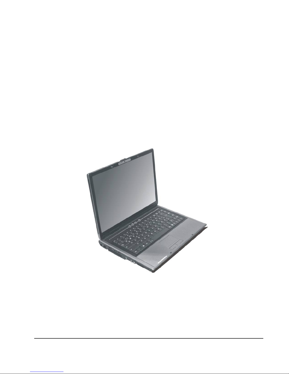
About Your Notebook Computer
Congratulation for having purchased your new Professional
Multimedia Notebook. This notebook incorporates the newest
features to serve all your computing needs.
26
Page 27
Notebook User Guide
About Your User Guide
Welcome to your Professional Multimedia Notebook User
Guide. This manual introduces you to the basic concepts of your
new computer.
This manual is divided into eight chapters.
Chapter 1 Introduction
Chapter 2 Getting Started
Chapter 3 Using Your Notebook Computer
Chapter 4 Multimedia Setup
Chapter 5 Connecting External devices
Chapter 6 System BIOS Setup
Chapter 7 Upgrade Options
Chapter 8 Care and Maintenance
Appendix A System Specifications
27
Page 28

Notebook User Guide
Table of Contents
ABOUT YOUR NOTEBOOK COMPUTER........................................ 26
ABOUT YOUR USER GUIDE............................................................... 27
1 INTRODUCTION............................................................................. 33
1.1 F
EATURE HIGHLIGHT .................................................................... 34
1.2 U
NPACKING THE COMPUTER ......................................................... 36
1.3 T
HE INSIDE OF THE NOTEBOOK ..................................................... 36
Notebook Status Icons.................................................................. 39
The Function of Easy Buttons ...................................................... 41
1.4 T
HE FRONT SIDE OF THE NOTEBOOK............................................. 42
1.5 T
HE REAR SIDE OF THE NOTEBOOK............................................... 42
1.6 T
HE LEFT SIDE OF THE NOTEBOOK................................................ 44
1.7 T
HE RIGHT SIDE OF THE NOTEBOOK ............................................. 46
1.8 T
HE UNDERSIDE OF THE NOTEBOOK ............................................. 47
1.9 N
OTEBOOK ACCESSORIES.............................................................. 49
2 GETTING STARTED ...................................................................... 51
2.1 U
SING THE BATTERY PACK ........................................................... 52
Extending Battery Life.................................................................. 54
2.2 CONNECTING THE AC POWER SOURCE.......................................... 55
2.3 S
TARTING YOUR COMPUTER......................................................... 56
2.4 A
DJUSTING THE DISPLAY CONTROLS ............................................ 57
2.5 I
NSTALLING THE NOTEBOOK DEVICE DRIVERS ............................. 57
Installing Windows Vista from Optical Disk Drive......................... 58
driver installation note:................................................................ 58
Installing the Chipset Driver........................................................ 58
Installing the VGA Device Driver................................................ 59
Installing the Audio Device Driver .............................................. 59
28
Page 29

Notebook User Guide
Installing the Modem Device Driver............................................ 60
Installing Synaptics - Touch Pad driver....................................... 60
Installing the LAN Device Driver................................................. 61
Installing Bluetooth Device Driver ..............................................61
Installing Camera Driver.............................................................62
Installing Camera Utility (SM370)............................................... 62
Installing Camera Utility (VideoCap).......................................... 63
Installing Silent Mode&RF On_Off Utility .................................. 64
Installing the Wireless LAN Device Driver and Utility................64
Installing the Robson Device Driver and Utility.......................... 65
2.6 T
URNING OFF YOUR COMPUTER....................................................66
3 USING YOUR NOTEBOOK...........................................................69
3.1 STARTING YOUR OPERATING SYSTEM........................................... 70
3.2 U
NDERSTANDING THE KEYBOARD FUNCTIONS.............................. 70
Basic Keyboard Functions ........................................................... 73
Cursor Control Keys..................................................................... 74
Screen Control Keys..................................................................... 75
Windows Hot Keys........................................................................75
Special Function Keys.................................................................. 75
3.3 U
SING THE TOUCHPAD POINTING DEVIC E .......................................77
3.4 C
ONFIGURING YOUR SCREEN DISPLAY ......................................... 79
Possible Display Configurations.................................................. 80
Changing the Display Properties under Windows.................................. 80
3.5 K
NOWING THE POWER SAVING FEATURES .................................... 81
3.6 W
ORKING WITH THE BUILT-IN HDD...............................................82
3.7 H
OW TO ACCESS THE OPTICAL DRIVE........................................... 83
3.8 E
XPRESSCARD......................... ERROR! BOOKMARK NOT DEFINED.
What is ExpressCard ?................... Error! Bookmark not defined.
Inserting and Removing a ExpressCard........Error! Bookmark not
defined.
29
Page 30

Notebook User Guide
3.9 USING FLASH MEMORY CARDS..................................................... 85
What is Flash Memory Card?...................................................... 85
4 FUN WITH WINDOWS VISTA EXPERIENCE.......................... 89
4.1 WHAT IS WINDOWS VISTA? .......................................................... 90
4.2 G
ET READY FOR WINDOWS VISTA ................................................ 90
4.3 E
NJOY YOUR MULTIMEDIA APPLICATION ..................................... 93
Internet Explorer.......................................................................... 93
Windows Calendar....................................................................... 93
Windows Contacts........................................................................ 94
Windows Defender ....................................................................... 95
Windows DVD Maker................................................................... 96
Windows Fax and Scan ................................................................ 97
Windows Live Messenger Download ........................................... 98
Windows Mail............................................................................... 99
Windows Media Center.............................................................. 100
Windows Media Player .............................................................. 101
Windows Meeting Space............................................................. 101
Windows Movie Maker............................................................... 102
Windows Photo Gallery.............................................................. 103
Windows Update......................................................................... 104
Windows Sidebar and Gadgets................................................... 105
Gaming....................................................................................... 106
Windows Flip and Windows Flip 3D ......................................... 107
5 CONNECTING TO PERIPHERALS........................................... 109
5.1 U
SING THE USB PORT................................................................. 110
5.2 U
SING AN EXTERNAL MONITOR PORT................................................ 111
5.3 U
SING THE EXTERNAL AUDIO SYSTEM ....................................... 112
5.4 U
SING THE LAN PORT ................................................................ 113
5.7 U
SING THE WIRELESS LAN......................................................... 114
30
Page 31

Notebook User Guide
5.8 USING THE MODEM PORT............................................................114
6 CU S T O M I Z I N G Y O U R N O T E B O O K............................................117
6.1 RUNNING THE BIOS SETUP PROGRAM ........................................ 118
6.2 U
SING THE MAIN MENU SETUP ...................................................120
6.3 U
SING THE ADVANCED CMOS SETUP......................................... 122
6.4 S
ECURITY MENU SETUP .............................................................. 124
6.5 U
SING THE BOOT SETUP.............................................................. 126
6.6 H
OW TO EXIT THE SETUP PROGRAM............................................127
7 USING OPTIONS ........................................................................... 131
S
YSTEM UPGRADE.................................................................................132
7.1 M
EMORY UPGRADE.....................................................................132
Installing Memory Module.........................................................133
7.2 H
ARD DISK UPGRADE.................................................................. 134
7.3 WIRELESS MODULE INSTALLATION.............................................136
8 CARING FOR YOUR NOTEBOOK............................................137
8.1 I
MPORTANT SAFETY INSTRUCTIONS ............................................ 138
8.2 C
LEANING YOUR COMPUTER....................................................... 140
8.3 M
AINTAINING THE LCD QUALITY............................................... 141
8.4 M
AINTAINING YOUR HARD DISK ................................................ 141
8.5 B
ATTERY CARE GUIDELINES....................................................... 142
8.6 W
HEN YOU TRAVEL....................................................................143
APPENDIX A SYSTEM SPECIFICATION...................................... 145
Processor Unit............................................................................ 146
System Memory...........................................................................146
LCD Display...............................................................................146
VGA System ................................................................................ 146
Storage........................................................................................147
Audio System .............................................................................. 147
31
Page 32

Notebook User Guide
ExpressCard............................................................................... 147
Touchpad .................................................................................... 147
Keyboard.................................................................................... 148
Flash BIOS................................................................................. 148
I/O Ports..................................................................................... 148
Wireless devices ......................................................................... 148
AC/DC Power Supply Adapter................................................... 148
Battery........................................................................................ 148
Weight and Dimension ............................................................... 149
32
Page 33

Introduction1
1 Introduction
Your Notebook PC is a fully Windows compatible
portable personal computer. With the latest features
in mobile computing and multimedia technology, this
notebook makes a natural traveling companion. With
leap of technology and compact, your Notebook PC
runs on a whole wide range of general business,
personal productivity, entertainment, and p
applications. It is ideal for use in the office, at hom
and on the road.
rofessional
e,
Your Notebook PC makes an ideal choice for use in
the office, the schoolroom, at home, on the road and
all other occasions.
33
Page 34

Notebook User Guide
1.1 Feature Highlight
Before we go to identify each part of your Notebook PC, we will first
introduce you to other notable features of your computer.
Processing Unit
• Your notebook runs on Intel® Core
TM
2 Duo processor that is integrated
with 4MB L2 Cache. Check with your dealer on the CPU type and speed.
• Fully compatible with an entire library of PC software based on operating
systems such as Windows Vista.
Memory
This notebook provides two memory slots for installing DDR2 SDRAM 200-
pin SODIMM modules up to 4GB using 256MB, 512MB, 1024MB or 2048MB
DDR SDRAM modules.
Wide Screen LCD Display
Provides extraordinary 14" 1280 x 800 (16:10) wide screen LCD display for
you to watch DVD movie.
Wire ess LAN l
Intel® Wireless WiFi Link 4965AGN Network Connection (802.11a/b/g/n)
Graphic System
Provides blazing graphics controller embedded in Intel GM965 chipset.
Optical Disk Drive
Provides DVD/CD-RW Combo
34
Page 35

Introduction1
USB 2.0
Provides four USB2.0 ports for fastest I/O data transmission.
ExpressCard
Provides one ExpressCard slot for faster new-generation PC card solution.
Audio System
Compliant with Intel HD Audio (Azalia 2 channels)
PCI Express Architecture
Compared to AGP architecture, PCI Express™ architecture enhances I/O
bandwidth and advances graphics performance.
Flash BIOS
Flash BIOS allows you to easily upgrade the System BIOS using the Phoenix
Flash utility program.
Power and System Management
• Integrated SMM (System Management Mode) on system chipset that shuts
down components not in use to reduce power consumption. To execute
power management, you can set up the parameter in Power Options
properties by pointing your mouse to Control Panel of Windows.
• Closing the Notebook computer (lowering the cover) allows you to
suspend the system operation instantly and resume at the press of the
power button.
• System Password for User and Supervisor included on the BIOS SETUP
Program to protect unauthorized use of your computer.
35
Page 36

Notebook User Guide
1.2 Unpacking the Computer
Your computer comes securely packaged in a sturdy cardboard shipping
carton. Upon receiving your computer, open the carton and carefully remove
the contents. In addition to this User Guide, the shipping carton should also
contain the following items:
; The Notebook Computer
; An AC Adapter and AC Power Cord
; Li-Ion Battery Pack
; CD with Driver Utility and Electronic-book
; Quick Setup Manual
Carefully inspect each component to make sure that nothing is missing and/or
damaged. If any of these items is missing or damaged, notify your dealer
immediately. Be sure to save the shipping materials and the carton in case you
need to ship the computer or if you plan to store the computer away sometime
in the future.
1.3 The Inside of the Notebook
The notebook computer is compact with features on every side. First, look
at the inside of the system. The following sections describe inside features.
36
Page 37

Introduction1
1. Color Widescreen LCD Display 2.7. Built-in Stereo Speaker
3. Keyboard 4. LED Indicators
5. Easy Buttons 6. Power On/Resume Button
8. Touchpad Pointing Device
• Color Widescreen LCD Display
The notebook computer comes with a color LCD that you can adjust for a
comfortable viewing position. The LCD is 14” TFT color LCD with
1280x800 (Wide XGA with ratio 16:10) resolution panels. The features of
the Color LCD Display are summarized as follows:
⇓ TFT color LCD with Widescreen 14” 1280x800 (Wide XGA)
resolution panels.
⇓ Capable of displaying 16M colors (32-bit true color) on either size
panels.
⇓ LCD display control hot-keys allows you to adjust the brightness of
the LCD.
37
Page 38

Notebook User Guide
⇓
Simultaneous display capability for LCD and external desktop
computer monitor.
• Built-in Stereo Speakers
Integrated left and right mini stereo speakers for sound and audio output
for your multimedia presentations or listening pleasure.
• Keyboard
⇓ Standard QWERTY-key layout and full-sized 87 keys keyboard with
Windows system hot-keys, embedded numeric keypad, 6 hot keys,
inverted "T" cursor arrow keys, and separate page screen control
keys.
⇓ Wide extra space below the keyboard panel for your wrist or palm to
sit-on comfortably during typing.
• LED Indicators
Keeps you informed of your notebook computer’s current power status
and operating status. Description of the status icons appears in the latter
part of this section.
• Easy Buttons
There are three easy buttons used for CPU throttling, accessing Internet
and Wireless LAN functions instantly and easily. Description of the easy
buttons appears in the latter part of this section.
• Power On/Resume Button
Switches the computer power on and off, or resumes whenever it is in
Suspend mode.
38
Page 39

Introduction1
• Touchpad Pointing Device
Microsoft mouse compatible with two Touchpad click buttons. The two
select buttons located at each side support tapping selection and dragging
functions. These buttons work like a standard computer mouse. Simply
move your fingertip over the touchpad to control the position of the
cursor. Use the selection buttons below the touchpad to select menu
items.
NOTEBOOK STATUS ICONS
The Status LED Panel keeps you informed of the notebook’s current power
and operating status. Each LED is marked with an icon to designate the
system status.
1. Power Indicator 2. Battery Charging LED
3. Drive Access 4. Wireless LAN Access
5. Caps Lock 6. Scroll Lock
7. Num Lock
• Power Indicator
Lets you know that power to the system is turned on. This LED is
positioned so that you can see the power state whether the LCD panel is
opened or closed.
⇓ Lights green when the system is powered on.
39
Page 40

Notebook User Guide
⇓
Lights green blinking when the system is in Standby mode.
⇓ Lights yellow when the battery power is low.
⇓ Lights orange when the battery power is critical low.
• Battery Charging LED
Lights to indicate battery in charging status.
⇓ Lights orange to indicate that the battery is in charging.
⇓ Lights orange blinking when the battery charging is in error.
⇓ Lights green to indicate the battery is fully charged or no battery
installed.
• Drive Access
When LED in blue blinking light indicates that the system is accessing the
Hard Disk or Optical Disk Drive.
• Wireless LAN access
When LED in blue light indicates that the wireless LAN module is
activated. When LED lights off, it indicates that the function is disabled.
• Caps Lock
When LED in blue light indicates that the Caps Lock key on the keyboard
is activated. When activated, all alphabet keys typed in will be in uppercase
or capital letters.
• Scroll Lock
When LED in blue indicates that the Scroll Lock key on the keyboard is
activated. The Scroll Lock key has different functions depending on the
software you are using.
40
Page 41

Introduction1
• Num Lock
When LED in blue light indicates that the Num Lock key on the keyboard
is activated. When activated, the embedded numeric keypad will be
enabled.
THE FUNCTION OF EASY BUTTONS
1. Wireless LAN Button 2. Internet Button 3. CPU Throttling
• Wireless LAN Button
Push this button to activate or inactivate the Wireless LAN. When you
activate the wireless LAN function, it will search the wireless LAN signal
automatically if you had installed the driver.
• Internet Button
This technology is designed specifically for providing a very convenient
way in connecting Internet only by pressing Internet button as shown in
the graphics. Just Press this button to open the Internet Explorer directly.
• CPU Throttling
41
Page 42

Notebook User Guide
Press this button to decrease the CPU performance speed in order to save
power for extending battery life and operation time.
1.4 The Front Side of the Notebook
1. Cover Switch
• Cover Switch
The cover (LCD panel) is locked when it is closed. Slide the button right
aside to release the latch for opening the cover of the computer.
1.5 The Rear Side of the Notebook
The system ports at the back of your notebook computer can connect various
devices. Each port is described as followings.
42
Page 43

Introduction1
1. Kensington Lock Hole 2. VGA Port
• Locking Device Keyhole
Lets you attach a Kensington security system or a compatible lock to
physically secure your notebook computer.
• VGA Port
Lets you attach an external monitor or projector for wider display. You
can run the LCD display and the external monitor simultaneously or
switch it to monitor only using the display hot-key.
43
Page 44

Notebook User Guide
1.6 The Left Side of the Notebook
The left side of your notebook computer provides the features shown in the
following figure.
1. DC Power Port 2. LAN Port
3. USB 2.0 Ports 4. Air-Outlet Vent
5. Headphone Jack 6. Line-In Jack
7.
Microphone Jack 8. 4 in 1 card slot
9. PC-Card Slot
• DC Power Port
Lets you connect the AC power adapter in supplying continuous power to
your notebook and recharging the battery.
• LAN Port
An internal 10Base-T/100Base-TX Ethernet LAN module connects your
computer to other computers/networks through a local area network
(LAN).
44
Page 45

Introduction1
• USB 2.0 Ports
The Universal Serial Bus (USB) port allows you to connect USB 2.0-
compliant devices (for example, printers, scanners and so on) to your
notebook computer.
• Air-Outlet Vent
Emits the heat out of your computer and keeps it within operating
temperature.
• Headphone Jack (with SPDIF out)
Lets you plug in a stereo headphone, powered speakers, or earphone set
with 1/8 inch phono plug for personal listening. (The SPDIF transmits
digitized audio signal by optical fiber. The external audio amplifier can get
the best audio quality without loss.)
• Line-In Jack
Lets you connect audio sources, such as external CD, players to this jack
for recording on your computer or playback through the Line-Out device.
• Microphone Jack
Allows you to connect an external microphone for monophonic sound
recording directly into your notebook computer.
• 4 in 1 card slot
The card slot supports SD, MMC, MS (Memory Stick) and MS_Pro flash
memory card format. You can use either of the 4 types flash memory
cards for extra storage media. Please pay attention to correct direction
when you insert the flash memory card. For more detail of flash card, you
can refer to Chapter 3.9
• PC-Card Slot
A newly developed PC Card interface, its connector has 68 pins and has a
potential transfer rate of up to 133 Mbps.
45
Page 46

Notebook User Guide
1.7 The Right Side of the Notebook
The right side of the notebook computer offers the features shown in the
following figure.
1. Optical Disk Drive 2. USB 2.0 Ports 3. Modem Port
Right Side Features
• Optical Disk Drive
Allows you to load and start programs from a compact disc (CD) or a
digital video disc (DVD) and play conventional audio CDs. It also can
make CD/DVD by using CD-R/RW or DVD-R/RW. (Burning DVD is
only possible with models equipped with a DVD burner)
• USB 2.0 Ports
The Universal Serial Bus (USB) port allows you to connect USB 2.0-
compliant devices (for example, printers, scanners and so on) to your
notebook computer.
• Modem Port
A 56K internal fax/data modem is installed. It keeps you connected to the
outside world through phone line.
46
Page 47

Introduction1
+
For electrical safety concerns, only use telephone cables rated 26AWG or
higher.
When using your telephone equipment, basic safety precautions should always
be followed to reduce the risk of fire, electric shock and injury to persons,
including the following:
1. Do not use this product near water, for example, near a bath tub, wash
bowl, kitchen sink or laundry tub, in a wet basement or near a swimming
pool.
2. Avoid using a telephone (other than a cordless type) during an electrical
s orm. There may be a remote risk of electric shock from lightning. t
3. Do not use the telephone to report a gas leak in the vicinity of the leak.
4. Use only the power cord and batteries indicated in this manual. Do not
dispose of batteries in a fire. They may explode. Check with local codes for
possible special disposal instructions.
• Optical Disk Drive
Allows you to load and start programs from a compact disc (CD) or a
digital video disc (DVD) and play conventional audio CDs. It also can
make CD/DVD by using CD-R/RW or DVD-R/RW.
1.8 The Underside of the Notebook
The bottom of the notebook computer offers the following features.
47
Page 48

Notebook User Guide
1. Battery Bay 2. Battery Release Latch
3. Hard Disk Compartment 4. Battery Lock Latch
5. 6. Memory Compartment
Bottom of the System
• Battery Bay
Equipped with a choice of Lithium-Ion (Li-Ion) battery pack.
• Battery Release Latch
To release the battery, first locate the Battery Lock Latch at the left side
with unlock status, then push the Battery Release Latch to the right end to
remove the battery pack.
• Hard Disk Compartment
Open this cover of this compartment to replace with other Hard Disk
Drive. Please refer to Chapter 7 for how to replace it.
• Battery Lock Latch
Push the latch to the lock side to lock and secure the battery, or push the
latch to the unlock side for unpacking the battery pack.
• FAN
• Memory Compartment
There are two SO-DIMM memory slots. One memory slot is empty for
upgrade usage.
48
Page 49

Introduction1
1.9 Notebook Accessories
AC Adapter
The AC Adapter supplies external power to your notebook computer and
charges the internal battery pack simultaneously. The AC adapter has an auto-
switching design that can connect to any 100VAC ~ 240VAC power outlets.
You just change the power cord if you are going to use your notebook in other
countries with different connector outlets.
When you connect the AC adapter, it charges the battery whether or not the
notebook computer is powered on.
Battery Pack
Aside from the AC adapter, your computer can also be powered through the
internal battery pack. The battery pack uses rechargeable Lithium-Ion (Li-Ion)
battery cells that provide long computing hours when fully charged and power
management enabled. You should always leave the battery inside your
computer even when using the AC adapter as it also acts as a back-up power
supply in case power from the AC adapter is cut off. It is also very important
to have the battery pack always charged to prevent battery cell degradation.
49
Page 50

Notebook User Guide
This page is intended to be blank.
50
Page 51

Getting Started 2
2 Getting Started
Your Notebook is designed and pre-configured for
easy setup and use. This chapter describes the
installation steps you should follow to get the
notebook up and running as quickly as possible.
51
Page 52

Notebook User Guide
2.1 Using the Battery Pack
The notebook is designed to operate with one of the following power sources:
• With AC power using the AC adapter connected to an electrical outlet.
• With a Lithium-Ion (Li-Ion) battery pack.
You should use the AC adapter whenever it is possible, relying on the battery
pack only when AC power is unavailable.
Before you use your notebook computer, install and recharge the battery pack
first. The rechargeable Li-Ion battery pack allows you to operate the notebook
without an external power source. When you connect the AC power adapter,
the battery immediately starts to recharge. Normal battery charging time is 2
hours for Lithium-Ion (Li-Ion) battery pack when your computer is turned off.
For maximum battery performance, fully discharge the battery first before
recharging it when you start to use it first time. To do so, unplug the AC
adapter, turn off power management features (through Setup and Windows),
and turn on the system. Once the battery is fully discharged, plug in the AC
adapter and recharge the battery. You can also do it by using the Battery
Refresh function in BIOS setup menu that is described on chapter 6.6
If you do not discharge the battery completely, it fails to accept a full recharge.
+
Li-Ion battery is vulnerable, do not charge it with other power adapter, or it
may cause fire or explosion.
52
Page 53

Getting Started 2
Installing the Battery Pack
This notebook provides the most convenient way to install the battery pack
into your computer. With the extended nose directed toward the compartment,
insert and push the battery pack.
Removing the Battery Pack
To remove the battery pack, slide the lock latch to the end of left side to
unlock the battery lock latch (1), and slide the battery release latch to the end
of right side to release the battery latch (2), then take out the battery pack with
your finger (3).
53
Page 54

Notebook User Guide
Replacing the Battery Pack
When your notebook estimates that the battery only has enough charge to
continue for a few minutes, it will alert you with a battery low warning beep. If
you are consuming a lot of power by using the audio system, the ExpressCard
slots, the hard disk drives, and optical disk drive, your notebook might run out
of charge much sooner than you expect. You should always respond to the
battery low indication by connecting to AC power or turning off your
notebook, or suspending your notebook to disk. If you do not do so, the
notebook will automatically suspend to disk and turn off. The contents of the
memory will store in the hard disk drive. You will be unable to restart the
notebook until you have connected to the AC adapter or installed a charged
battery. To replace the battery pack, refer to the previous sections on
"Installing the Battery Pack" and "Removing the Battery Pack."
+
For Window XP, the suspend mode (Hibernate or Standby) can be chosen
at Power Options of Windows's Control Panel)
+
Be sure to save your data before replacing the battery pack or connecting
the AC adapter. Failure to do so can result in data loss.
EXTENDING BATTERY LIFE
It is important to be aware of the simple things for extending the life of the
system main battery while you are on the road. You should find a working
place where the external lighting is not too bright and turn down the screen
brightness. Also, you can choose the available mode on the Power
Management item of the Control Panel in Windows.
54
Page 55

Getting Started 2
2.2 Connecting the AC Power Source
The AC adapter provides external power source to your computer and charges
the internal battery pack at the same time. The AC adapter also has an auto-
switching design that can connect to any 100VAC ~ 240VAC power outlets.
To connect the power adapter:
1. Plug the AC power cord into the power socket of the AC power adapter.
2. Plug the other end of the AC power cord to a live AC wall outlet.
3. Plug the connector of the AC adapter to the DC-IN port found at the left
side of the computer.
+
Whenever possible, it is advisable to always have the AC adapter connected
to the notebook and the battery pack installed. This ensures continuous
power supply and prevents any data loss incurring from sudden power
breakdown.
55
Page 56

Notebook User Guide
+
y For the power supply of this equipment, an approved power cord has to
be used.
y Make sure the socket and any extension cord(s) you use can support
the total current load of all the connected devices.
y Before cleaning the computer, make sure it is disconnected from any
external power supplies (i.e. AC adapter).
2.3 Starting Your Computer
The Power/Resume button is found on the top of the base unit. Press the
Power/Resume button to start your computer and check that if the Power
LED turns on.
After a few seconds, the computer’s display will turn on and your computer
will begin to execute the Power On Self Test or POST to check if all system
components are running properly. Any error found during the test will be
displayed on the screen and may generate short beep sound as well.
56
Page 57

Getting Started 2
After the test, the screen will also display a message "press <F2> to enter
SETUP". You don’t need to run this program at the moment as your dealer
already made the necessary settings for your computer optimal operation.
Refer to Chapter 6 on running the SETUP program later.
After the test has completed, your computer will start to search and boot up
the operating system from your hard drive. The notebook computer normally
comes with a Windows operating system pre-installed in your hard drive.
Consult the Windows manual on how to use the program. If not, contact your
dealer for assistance.
2.4 Adjusting the Display Controls
The LCD brightness adjustment is controlled by <Fn> +<F8> and <Fn> +
<F9> keys respectively. You need to press these hot-key controls after
powering on your notebook to suit your viewing pleasure.
The Brightness hot-key control adjusts the brightness on the LCD. The
brightness hot-key control will not set the LCD completely dark or bright; it
provides sufficient lighting to the LCD to match the external lighting of the
surrounding. The brighter the room, the more you need to increase the
brightness of the LCD.
2.5 Installing the Notebook Device
Drivers
If you already have an operating system installed into your notebook computer,
it is best to install the needed device drivers for using the built-in devices of
your computer. Before installing the drivers, check with your dealer first if they
57
Page 58

Notebook User Guide
have already installed all the drivers along with the operating system. If not,
follow the procedures below:
INSTALLING WINDOWS VISTA FROM OPTICAL DISK DRIVE
To install Windows Vista directly from your optical disk drive, please go to
Boot menu of BIOS setup menu. Use arrow key to select "DVD/CD-ROM
Drive", then use "+" or "-" to move it to the top. Go to Exit menu and select
"Exit Saving Changes". Accordingly, insert the Windows Vista installation
CD into optical disk drive with following the instructions on the screen to
finish the installation.
DRIVER INSTALLATION NOTE:
+
Please be notified that whenever you install the driver utility, it should be
install the CHIPSET Driver first.
INSTALLING THE CHIPSET DRIVER
Your notebook computer uses the advanced chipset. Installing the driver to
enhance the stability and performance.
Installing Chipset device driver for Windows Vista 32
1. Click the Start button, then point to Run. The Run dialog box appears.
2. Click the Browse button and specify the directory as.
"E:\Drivers\Vista 32\Chipset\Setup.exe".
3. When computer appears User Account Control window, click “Allow”
for accessing the computer.
4. Click “Next” continuously to install this driver when screen displays this
command.
58
Page 59

Getting Started 2
5. Click “Yes” to accept the License Agreement.
6. Click “Next” to continue the following step.
7. Tick the option "Yes, I want to restart my computer now.",
and press Finish to restart your system.
INSTALLING THE VGA DEVICE DRIVER
Following is the procedure for installing the Video Accelerator 3D Adapter
VGA driver to your computer:
Installing VGA device driver for Windows Vista 32
1. Click the Start button, then point to Run. The Run dialog box appears.
2. Click the Browse button and specify the directory as.
"E:\Drivers\Vista 32\VGA\Setup.exe".
3. When computer appears User Account Control window, click
“Continue” for accessing the computer
4. Click Next to install this driver when screen displays this command.
5. Click “Yes” to accept the License Agreement.
6. Click “Next” to continue the following step.
7. Tick the option "Yes, I want to restart my computer now.", and press
Finish to restart your system.
INSTALLING THE AUDIO DEVICE DRIVER
Your notebook computer uses the Realtek Audio controller.
Installing Audio device driver for Windows Vista 32
1. Click the Start button, then point to Run. The Run dialog box appears.
59
Page 60

Notebook User Guide
2. Click the Browse button and specify the directory as.
"E:\Drivers\Vista 32\Audio\Setup.exe"
where the audio driver is located.
3. When computer appears User Account Control window, click
“Continue” for accessing the computer
4. Click “Next” to continue the following steps.
5. Tick the option "Yes, I want to restart my computer now.",
and press “Finish” to restart your system.
INSTALLING THE MODEM DEVICE DRIVER
Please follow the procedures below for installing the Conexant System Azalia
Modem driver:
Installing Modem driver for Windows Vista 32
1. Click the Start button, then point to Run. The Run dialog box appears.
2. Click Browse button and navigate to the directory as
"E:\Drivers\Vista 32\modem\setup.exe"
3. When computer appears User Account Control window, click “Allow”
for accessing the computer
4. Click “OK” to complete it.
INSTALLING SYNAPTICS - TOUCH PAD DRIVER
Installing Synaptics - Touch Pad driver for Windows Vista32
1. Click the Start button, then point to Run. The Run dialog box appears.
2. Click the Browse button and specify the directory as.
60
Page 61

Getting Started 2
"E:\Drivers\Vista 32\Touch Pad\Setup.exe".
3. When computer appears User Account Control window, click
“Continue” for accessing the computer
4. Click "Next" to continue the following step.
5. Click "Finish" and then press "Restart Now" to restart your system.
INSTALLING THE LAN DEVICE DRIVER
Please follow the procedures below for installing the LAN driver:
Installing LAN driver for Windows Vista 32
1. Click the Start button, then point to Run. The Run dialog box appears.
2. Click the Browse button and specify the directory as.
"E:\Drivers\Vista32\LAN\SetupYukonWin_5X6E.exe"
3. When computer appears User Account Control window, click “Allow”
for accessing the computer
4. Click “Next” to continue the following steps.
5. Choose “I accept the terms in the license agreement” and click
“Next”.
6. Click “Install” to implement the setup program to install this driver.
INSTALLING BLUETOOTH DEVICE DRIVER
Please follow the procedures below for installing the Bluetooth driver:
Installing Bluetooth driver for Vista 32
1. Click the Start button, then point to Run. The Run dialog box appears.
61
Page 62

Notebook User Guide
2. Click the Browse button and specify the directory as.
"E:\Drivers\Vista32\Blue tooth\Setup.exe"
3. When computer appears User Account Control window, click
“Continue” for accessing the computer.
4. Click “Next” to continue the following steps.
5. Choose “I accept the terms in the license agreement” and click
“Next”
6. Click “Install” to implement setup program to install this driver.
7. Click “Finish” and then press “Yes” to restart your system..
INSTALLING CAMERA DRIVER
Please follow the procedures below for installing the Camera Driver:
Installing Camera Driver for Vis a 32 t
1. Click the Start button, then point to Run. The Run dialog box appears.
2. Click the Browse button and specify the directory as.
"E:\Drivers\Vista32\Camera\setup.exe"
3. When computer appears User Account Control window, click
“Continue” for accessing the computer
4. Click “Next” to continue the following steps.
5. Click “Finish” and “Restart Now” to complete it.
INSTALLING CAMERA UTILITY (SM370)
Please follow the procedures below for installing the Camera Utility:
62
Page 63

Getting Started 2
Installing Camera Utility for Vista 32
1. Click the Start button, then point to Run. The Run dialog box appears.
2. Click the Browse button and specify the directory as.
"E:\Drivers\Vista32\CameraUtility\SM370\setup.exe"
3.
When computer appears User Account Control window, click
“Continue” for accessing the computer.
4.
Click “Next” to continue the following steps.
5.
Click “Install” to implement setup program to install the utility.
6.
Click “Finish” to complete it.
INSTALLING CAMERA UTILITY (VIDEOCAP)
Please follow the procedures below for installing the Camera Utility:
Installing Camera_hotkey Utility for Vista 32
1. Click the Start button, then point to Run. The Run dialog box appears.
2.
Click the Browse button and specify the directory as.
"E:\Drivers\Vista32\CameraUtility\VideoCap\setup.exe"
3.
When computer appears User Account Control window, click
“Continue” for accessing the computer.
4.
Click “Next” to continue the following steps.
5.
Click “I Agree” to continue the following steps.
6. Click “Install” to implement setup program to install the utility.
7. Click “Finish” to complete it.
63
Page 64

Notebook User Guide
INSTALLING SILENT MODE&RF ON_OFF UTILITY
Please follow the procedures below for installing the Power Management
Utility:
Installing Silent Mode&RF On_Off Utility for Windows Vista 32
1. Click the Start button, then point to Run. The Run dialog box appears.
2. Click the Browse button and specify the directory as.
"E:\Drivers\Vista32\Silent Mode&RF On_Off\setup.exe"
3. When computer appears User Account Control window, click “Allow”
for accessing the computer
4. Click “Next” to continue the following steps.
5. Click “Install” to implement setup program to install the utility.
6. Tick the option “Launch Power Manager”, and click “Finish” to
complete it.
INSTALLING THE WIRELESS LAN DEVICE DRIVER AND
UTILITY
INSTALLING THE WIRELESS LAN DRIVER AND UTILITY
Please follow the procedures below for installing the Wireless LAN Adapter
driver:
Installing Wireless LAN driver and Utility for Windows Vista 32
1. Click the Start button and then click Run. The Run dialog box appears.
2. Click Browse button and specify the directory as
“E:\Drivers\Vista32\Wireless LAN\Autorun.exe”
64
Page 65

Getting Started 2
3. When computer appears User Account Control window, click
“Continue” for accessing the computer
4. Click "Install Softeare" to execute the setup program.
5. Tick the option “I accept the terms in the license agreement”, and
click Next for further step processing
6. Tick the option “Typical”, and click Next again.
7. Click “OK” to complete it.
INSTALLING THE ROBSON DEVICE DRIVER AND
UTILITY
INSTALLING THE ROBSON DRIVER AND UTILITY
Please follow the procedures below for installing the Robson driver:
Installing Robson driver and Utility for Windows Vista 32
1. Click the Start button, then point to Run. The Run dialog box appears.
2. Click Browse button and specify the directory as
“E:\Drivers\Vista32\Robson\setup.exe”
3. When computer appears User Account Control window, click “Allow”
for accessing the computer
4. Click “Next” continuously to install this driver when screen displays this
command
5. Click “Yes” to accept the License A greement.
6. Click “Next” to continue the following step.
7. When computer appears Windows Security window, click “Install” for
accessing the computer
65
Page 66

Notebook User Guide
8. Click “Next” again.
9. Tick the option "Yes, I want to restart my computer now.", and press
“Finish” to restart your system.
2.6 Turning off Your Computer
If you are not going to use the computer for a while, it is best to turn off the
power of the computer for longer use. Before turning off the power, you need
to close first all application programs and shutdown the operating system.
After turning off the computer, make it a habit to leave the LVDS panel open
for a while whenever used for an extended period of time. This allows the
inside parts of the computer to cool off. Closing the panel will force the heat
up against the LCD screen, which may degrade the LCD when done regularly.
More importantly, never close the LVDS panel for a long period of time when
computer is on and power saving features are disabled.
66
Page 67

Getting Started 2
67
Page 68

Page 69

Using Your Notebook 3
3 Using Your Notebook
This chapter describes how to operate the standard
built-in features of the notebook that you normally would
use in your day-to-day computer work. If you are new to
computers and to your operating system, you also need to
read the manual for the operating system on how to work
with your computer. It is very important to familiarize
yourself well with the operating system. The succeeding
chapters not only guide you to go beyond the basics, but
also try other exciting features.
69
Page 70

Notebook User Guide
3.1 Starting Your Operating System
The operating system is a must ingredient in using your computer. Without an
operating system, it is like playing chess without the chessboard. It is the
platform for all your software application programs to run on. The most
popular operating system today is Microsoft Windows. You should have
installed one operating system by your dealer unless you are an expert
computer user and would need a more powerful operating system. If you have
an operating system already installed in your computer, then you would be up
and running after you power on your computer and boot up the system. Check
your operating system manual on how to run it.
3.2 Understanding the Keyboard
Functions
Your notebook computer is equipped with an 87 keys keyboard that provides
all the functionality of a full-sized 101 or 102-key keyboard. Aside from the
standard typewriter-layout keyboard of your computer, there are a number of
extra features and function controls on the built-in keyboard including
Windows system hot keys.
70
Page 71

Using Your Notebook 3
1. Function Keys 2. Control Keys
3. Windows Start Menu Key 4. Control Keys
5. Windows Shortcut Key 6. Cursor Control Keys
Keyboard
Key features and operations are described below:
• Function Keys
Function keys are application-driven, like F1 through F12 can be found on
the keyboard. These keys work together with the Fn key to activate special
functions. Some keys (printed in blue on keypad) are preprogrammed with
dual functions.
• Control keys — Ctrl, Alt, Fn, and Shift are controls used in conjunction
with other keys to change their functions. To use control keys, press and
hold the control key while pressing another key. For example, "Press Ctrl-
C" means to hold down the Ctrl key and type the letter C. Key
combinations work especially to the application you are running.
71
Page 72

Notebook User Guide
• Windows keys
Use the following two keys to facilitate your work:
⇓ Start Menu key
Displays the Start menu.
⇓ Shortcut/Application key
Provides quick access to shortcut menus. This key acts like a right
mouse button.
• Cursor Control keys
Cursor control keys let you position the cursor on the screen where you
want. In the screen, the cursor is a blinking underline, block, or vertical
bar depending on the application. The cursor indicates where the next text
typed is inserted.
• Typewriter keys
Typewriter keys (also called alphanumeric keys) are used to enter text and
characters. Keys with blue print on them behave differently when
combined with control keys.
72
Page 73

Using Your Notebook 3
BASIC KEYBOARD FUNCTIONS
Keypad Function Description
<Enter> key. Execute a command. Within many
text editing application programs, the <Enter> key
inserts a hard carriage return, just like what ordinary
typewriter does.
<Esc> key. Press this key to cancel or escape from
a command or function.
<Ins> key. Known as the Insert key. Press this key
to toggle the keyboard data entry from insert to type
over mode.
<PrtScr> key. Known as the Print Screen key. Press
this key to map the whole screen to share memory for
your specific usage.
<Del> key. Known as the Delete key. Press this key
to delete the character to the right of the cursor, or
delete marked texts or items.
<Pause> key. Press this key to temporarily halt
execution of a command. Pressing any other key to
resume execution of a command.
<Backspace> key. Press this key to delete the
character to the left of the cursor.
<Shift> key. Press this key in combination with
alphabet letters to produce uppercase letters in
typing. Use this key in combination with those twocharacter keys (found on the second row of the
keyboard) to produce the upper marked keys. Also
used in most application program in combination
with other keys to execute a certain command.
<Tab> key. Press this key to move the cursor to the
next tab stop on the right. This key works much the
same as in ordinary typewriter.
73
Page 74

Notebook User Guide
Keypad Function Description
<Ctrl> key. Known as the Control key. Used in
most application program in combination with other
keys to execute a certain command.
<Alt> key. Known as the Alternate key. Used in
most application program in combination with other
keys to execute a certain command.
+
<Fn> + <Num Lock> key. Activates the
embedded 15-key numeric keypad. The keys are
color coded blue.
<Caps Lock> key. Used in most application
program to always activate uppercase alphabet
characters.
+
<Fn> + <Scroll Lock> key. Used in most
application program to scroll the screen without
having to move the cursor.
CURSOR CONTROL KEYS
Keypad Function Description
Up arrow key. Moves the cursor up one line at a
time.
Down arrow key. Moves the cursor down one
line at a time.
Left arrow key. Moves the cursor to the left one
space at a time.
Right arrow key. Moves the cursor to the right
one space at a time.
74
Page 75

Using Your Notebook 3
SCREEN CONTROL KEYS
Keypad Function Description
<Home> key. Moves the cursor to the
beginning of a screen or line.
<PgUp> key. Moves the cursor up one
screen at a time
<PgDn> key. Moves the cursor down one
screen at a time
<End> key. Moves the cursor to the end of a
screen or line.
WINDOWS HOT KEYS
Keypad Function Description
<Start> key. Pulls up the Windows Start menu.
<Right Click> key. Performs a mouse right-click
function for Windows system.
SPECIAL FUNCTION KEYS
The notebook has special system function keys that activate key serving dual
functions. When pressed in conjunction with the <Fn> key, these keys set
specific system parameters and are sometimes referred to as "hot keys".
75
Page 76

Notebook User Guide
Keypad Function Description
+
To enable the Web Camera function.
+
Switches display between LCD, CRT, or
LCD and CRT simultaneously.
+
To shut down or resume the built-in
system speaker volume.
+
Decreases the brightness of LCD display
incrementally.
+
Increases the brightness of LCD display
incrementally.
+
Decreases the audio volume of the
notebook incrementally.
+
Increases the audio volume of the
notebook incrementally.
+
To close or resume the touchpad function.
76
Page 77

Using Your Notebook 3
3.3 Using the Touchpad Pointing Device
Your computer comes with a built-in touchpad pointing device that is found
on the center of the palm-rest surface.
The touchpad offers a number of options that let you customize how it
functions. To access these options, locate the Control Panel and double click
on the Mouse icon. The options let you control the size and color of the
cursor, cursor speed, the accepted double-click speed, and selection button
orientation.
The touchpad works a mouse pointing device replacement that is used under
Windows-based operating system. You can use the standard Microsoft driver
that is compatible with the touchpad device and is normally used under
Windows-based operating system. However, if you want to utilize the added
features of the touchpad, you may want to try installing its own device driver
that comes with added utilities for enhancing the function of the device.
77
Page 78

Notebook User Guide
1. Left Selection Button 2. Right Selection Button
3. Touchpad
Touchpad Features
Here how to use the touchpad pointing device:
1. The rectangular surface acts like a miniature duplicate of your display
screen. To move the mouse cursor, place the finger lightly on the sensor
pad and move in the desired direction. If you reach the end of the pad, lift
your finger and place it back down on the other side of the pad.
2. To select an item, click on the item by pressing the left button control or
by simply tapping on the surface once. A light, quick tap always works
best. To execute an item, click the left button twice or do a quick double
tap on the surface.
78
Page 79

Using Your Notebook 3
3. To simulate holding the mouse button down (dragging an icon or
selection), use the tap-and-drag gesture. This feels much like a double-
click, except that the finger remains on the pad after the second tap: Tap,
lift, tap, hold and move. The simulated button remains held as long as the
finger remains on the pad.
4. When you press both the Left and Right click button at the same time, the
auto Scroll function will be activated.
+
Avoid spilling any liquid on the touchpad surface and always keep the
touchpad surface and pointing finger dry from sweat built-up. Also do not
expose touchpad to any magnetic source object.
3.4 Configuring Your Screen Display
The VGA display function of your notebook is based on a high performance
AGP local bus controller and is fully VGA compatible. This controller offers a
large set of extended functions and higher resolutions especially useful when
you are connecting an external high-resolution and high-frequency CRT or
LCD.
Please Refer to Section 5 "Installing the Notebook Device Drivers" of Chapter
2 in this manual for the procedures on how to install the VGA device driver
under Windows. After installing the VGA driver, you would then configure the
display resolution or screen size to match your LCD display panel. This
notebook computer model provides Wide screen 15.4” 1280x800 (Wide XGA)
resolution panels. You would also probably want to set the amount of color
output to display sharper images and photos.
79
Page 80

Notebook User Guide
POSSIBLE DISPLAY CONFIGURATIONS
The table below shows you the possible display resolution you can set when
using either the LCD display or the external monitor (CRT):
Display Possible Resolution Maximum Colors
Widescreen
14” 1280x800
WXGA LCD
1280x800
1280x768
1152x864
1024x768
800x600
16 million colors
16 million colors
16 million colors
16 million colors
16 million colors
CRT Only 1400x1050
1280x1024
1152x768
1024x768
800x600
16 million colors
16 million colors
16 million colors
16 million colors
16 million colors
+
65,536 or 64K colors is also equivalent to 16-bit high color while 16 million or
16M colors is equivalent to 32-bit true color.
+
You can use the <Fn> + <F3> hot-key to switch the display between LCD
only, CRT only, or both LCD and CRT display.
CHANGING THE DISPLAY PROPERTIES UNDER WINDOWS
To change the display properties of your screen under Windows system, just
right-click on the desktop area and select Properties or go to the Control Panel
and click on the Display icon. The Display Properties dialog box will appear on
your screen. Click on the Settings tab to set your desired configuration. Make
sure to follow the configuration table above.
80
Page 81

Using Your Notebook 3
+
If you cannot configure the display properties, change the display driver
first as mentioned on Section 5 "Installing the Notebook Device Drivers" of
Chapter 2 in this manual. Consult your dealer for the latest Windows VGA
driver.
3.5 Knowing the Power Saving Features
Aside from its superior performance, one of the great features in your
notebook computer is the ability to conserve power. Your computer is
designed to incorporate intelligent and advanced power management functions
that turn off power of most components when system is idle or not in use.
This feature not only gives you longer battery life but also cools the systems
and components as well.
The definitions of Standby Mode, Hibernation Mode, and Shutdown are
depicted as follows:
Standby Mode
Standby Mode is mainly for power saving. When the Standby Mode is
activated, your display and hard drive are shut down and all open applications
and documents are stored in RAM (Random Access Memory). This allows
your notebook to wake up quickly, but a low level of power is required to
maintain this suspended state. How quickly your system powers down into
Standby mode is up to you by setting proper times in Power Options of
Control Panel in Window. While the notebook is in Standby mode, the LED
of power indicator flashes. To resume your working again
, you can press the
power button to return your work to the screen where you left off.
81
Page 82

Notebook User Guide
Hibernation Mode
In Hibernation mode, all system devices are powered down and the contents
of RAM are stored on your hard drive. Hibernate mode uses less power than
Standby mode, but takes a bit longer time to resume. When your notebook
goes into hibernation, Windows saves your entire desktop state before
powering down your computer. You don’t need to save and close each
document before you put your notebook into hibernation. When you press
power button again, system will bring your notebook out of hibernation. You'll
find your applications and documents open on your desktop exactly as you left
them.
Shutdown
All power has been turned off from the notebook. This means that no power
including external AC power source and battery power source will be consume
by the notebook.
3.6 Working with the Built-in HDD
Your notebook computer is equipped with a built-in large capacity 2.5 inch
hard disk drive where you store and run your computer’s operating system and
application software programs.
+
If you wish to replace your hard disk, contact your local dealer for more
information about this dealer-installable device.
82
Page 83

Using Your Notebook 3
3.7 How to Access the Optical Drive
Your system ships with an optical disk drive installed on the left side of your
computer. You would normally use the drive for installing operating system
and software application programs.
To insert and remove a disc on the drive:
1. Make sure the computer is turned on. Press the eject button found on the
door cover of the combo drive. The DVD/CD tray mechanism will pop-
out slightly and slowly pull out the whole length of the tray.
2. Place the disc on top of the DVD/CD tray with the label side facing up.
Gently press the compact disc onto the center spindle to secure the disc.
83
Page 84

Notebook User Guide
3. To remove the disc, press on the center spindle and pull up the disc from
the side until the disc snaps out of the spindle lock.
+
If the eject function is disabled by software or a power failure occurs, the
Emergency Eject Hole allows you to manually remove a CD from the
reader.
4. To close the combo drive, simply push the CD tray inside. The combo
drive LED will activate when the disc is detected. Wait until the LED has
turned off and then start to read the disc.
How to care the Optical Disks (CDs, DVDs, etc.)
When you handle CDs and DVDs, pay attention to the following guidelines:
• Always pick up the disk by its edges.
• Avoid scratching or soiling either side of the disk.
• Do not write with the hard ball-point pen or apply labels on either side of
the disk.
• Keep the disk away from direct sunlight or high temperatures.
• Clean fingerprints or dust from the disk by wiping it with a soft cloth.
The above points also apply to other optical storage media.
+
The optical drive is a Class 1 Laser Product.
84
Page 85

Using Your Notebook 3
3.8 Using Flash Memory Cards
WHAT IS FLASH MEMORY CARD?
Flash Memory is a memory storage media. It is used by most digital camera,
moreover, it can replace the traditional floppy disk. Flash memory card is built
with different form factor and brand name. Their size is smaller than PCMCIA
card. This computer supports most of the flash memory card, including SD,
MMC, MS (Memory Stick), and MS_Pro card.
The 4 in 1 card slot is used by the following cards as SD, MS (Memory Stick ),
MMC, and MS_Pro.
+
For a single moment, only one card can be inserted into the 4 in 1 card or
CF slot
Inserting Flash Memory Card
To insert a flash memory card into the slot is similar to ExpressCard. You only
need to pay more attention whenever insert the flash memory card into the slot
with the correct side.
For MMC and SD card, you should position the copper connector at the
bottom side. For Memory Stick card, you should position the copper
connector at the topside. All of these cards should be located at the center of
the slots in inserting.
Slot Card type Copper connector
4 in 1 SD (Secure Digital)
MMC (MultiMedia Card)
MS (Memory Stick)
MS_Pro
Bottom side
Bottom
Top side
Top side
85
Page 86

Notebook User Guide
Only one correct side can be accepted for the 4 in 1 card slots. If you cannot
insert the card into the 4 in 1 slot or you had inserted the card but it is not
recognized by the computer, please remove the card and turn the card upside
down and insert it again. To prevent the damage made both on card and the
slot, never forced an entry into the slot with incorrect side.
Removing Flash Memory Card
It is similar to ExpressCard for removing a flash memory card from the slot.
You should first disable the card setting in the system as described in the
former section.
To remove the flash memory card, you should only pull out the card by finger,
there is no release button for flash memory slot.
86
Page 87

Using Your Notebook 3
87
Page 88

Notebook User Guide
88
Page 89

Connecting to Peripherals 4
4 Fun with Windows Vista
Experience
This notebook integrated in a highly
compact platform is designed for
digital entertainment. With Windows
Vista, it offers a breakthrough user
experience and is designed to help you
feel confident in your ability to view,
find, and organize information and to
control your computing experience. It
simplifies our digital life in taking
charge of media, share moves, TV,
photos, and music with your friends
and family.
89
Page 90

Notebook User Guide
4.1 What is Windows Vista?
Windows Vista is an operating system that enables you to enjoy the best in
entertainment on your notebook.
The visual sophistication of Windows Vista helps streamline your computing
experience by refining common window elements so you can better focus on
the content on the screen rather than on how to access it.
With Windows Vista, you can store, share and enjoy all of your photos, all of
your music, all of your home video and even recorded TV. It’s all contained in
one control system. That is as easy to use with a great new user-friendly
interface.
4.2 Get Ready for Windows Vista
Windows Vista is designed to help make you more productive as you work
with your PC throughout the day with new features.
Starting the Windows Vista
When you start using Windows Vista, you will recognize familiar elements
such as the Start menu, which is now faster, more streamlined, and more
helpful than in previous versions of Windows. More than that, the new start
menu makes it very easy for you to navigate across all of the installed
applications on your PC. Eliminating the slow performing, cascading "All
Programs" view, the new start menu can help you get something started more
quickly than ever.
90
Page 91

Connecting to Peripherals 4
About the entertainment
To recall all default multimedia applications, click on “All Programs” located
on the left corner on the desktop, the “All Programs” will be changed to
“Back” as shown in the following figure.
91
Page 92

Notebook User Guide
It now becomes more easy to execute various application with just click on it.
Instant Search
The Start menu features integrated desktop search through a new feature
called Instant Search which can help you find and launch almost anything on
your PC. Just type in a word, a name, or a phrase, and Instant Search can find
the right file for you.
Use Instant Search to quickly find the information you need.
92
Page 93

Connecting to Peripherals 4
4.3 Enjoy Your Multimedia Application
INTERNET EXPLORER
Windows Vista enhances the Internet Explorer experience in finding and
displaying information, and Web sites on the Internet.
The upcoming release of Internet Explorer 7 not only adds important new
security and privacy features, but makes everyday tasks easier through features
such as tabbed browsing, inline search, and shrink-to-fit printing
WINDOWS CALENDAR
Windows Calendar helps you in management appointments and tasks by
creating personal calendar, publishing them, and subscribe to other users
calendars.
93
Page 94

Notebook User Guide
Windows Calendar is a flexible, easy-to-use calendar built directly into the
Windows Vista operating system. It lets you plan and manage all of your
activities and coordinate your schedule with others. It also lets you create a
personal task list and receive automatic notifications and reminders about
specific tasks and upcoming appointments.
Windows Calendar has a broad range of features to help you manage your
personal schedule
WINDOWS CONTACTS
Windows Contacts can store e-mail addresses and other information about
people and organizations.
94
Page 95

Connecting to Peripherals 4
Microsoft Windows Vista provides a new mechanism and user interface for
storing and retrieving information about people (contacts) who are important
to the users of Microsoft Outlook and Windows Mail (formerly Outlook
Express).
WINDOWS DEFENDER
Windows Defender is enable to protect the computer from spyware and other
potentially unwanted software.
95
Page 96

Notebook User Guide
Windows Defender helps protect computers against pop-ups, slow
performance, and security threats caused by spyware and other unwanted
software. Applications can check and change its status.
WINDOWS DVD MAKER
Windows DVD maker helps you burn pictures and video to DVD..
96
Page 97

Connecting to Peripherals 4
Windows DVD maker lets you create a DVD quickly, complete with
professional-looking menus, a scene selection page so viewers can easily find
what they are looking for, and even slide shows using your favorite songs as a
soundtrack.
WINDOWS FAX AND SCAN
Windows Fax and Scan help you send and receive faxes or scan pictures and
documents.
97
Page 98

Notebook User Guide
Faxing and scanning functions come together in Windows Vista through
Windows Fax and Scan. Sending and receiving faxes through your PC is now
as simple as performing the same tasks on a fax machine, especially for digital
document
WINDOWS LIVE MESSENGER DOWNLOAD
Windows Live Messenger Download can connect and share message instantly
on the world’s favorite IM service..
98
Page 99

Connecting to Peripherals 4
Windows Live Messenger is the next-generation MSN Messenger. It has
everything you already love about Messenger, and much more.
WINDOWS MAIL
Windows Mail can send and receive e-mail and newsgroup messages.
99
Page 100

Notebook User Guide
Windows Mail is designed to help you prevent emerged some annoyances and
risks that have grown over the years, that enables your e-mail experience is as
productive and fun as possible. Windows Mail includes features that help you
reduce the risks, while enjoying the many benefits, of e-mail
WINDOWS MEDIA CENTER
Windows Media Center lets you opens your home entertainment option for
digital and on-demand media, including TV, Movies, music and pictures.
It is enable to make you enjoy all your favorite digital entertainment—
including live and recorded TV, movies, music, and pictures—in one place
with the easy-to-use Windows Media Center menu system and remote control.
Windows Media Center in Windows Vista includes enhancements for
expanded support of digital and high-definition cable TV, an improved menu
system, and the ability to create a consumer-electronics-quality living-room
experience, as well as new options for multi-room access to your
entertainment through Media Center Extenders.
100
 Loading...