

OptiLinQ SMR1, SMR1P Owner's Manual
+12VDC
GND
STATUS
SIGNAL
EMITTERS
PWR
IR
RCVR
CB1
ONE ZONE
CONNECTING BLOCK
SMR1 Receiver
PS1
Power Supply
CB1
Connecting Block
Red (or white)
Stripe
120 VAC
(Unswitched)
REMOTE ROOM
MAIN ROOM
Hand Held
Remote
3-Terminal Block (supplied)
0.469"
2 1/4"
3-Conductor
Inter-room Cable
(unshielded OK)
OUT
+12V
GND
7 Foot Ribbon Cable
E1 Emitter
E1 Emitter
E1 Emitter
Satellite Receiver
AV Receiver
DVD/CD Player
The SMR1 and SMR1P are small IR receivers that have been designed primarily for mounting in panels,
doors, cabinets, etc. for control of A/V equipment behind closed doors. They may be mounted in walls,
ceilings, wall speakers, etc., virtually anywhere an inconspicuous appearance is desired. Their high sensitivity
allows placement behind speaker grilles and still receive IR commands up to 25 feet away. If longer range is
necessary, a 1/2-inch hole must be drilled in the grille to allow unobstructed entry of the IR signal.
INSTALLATION INSTRUCTIONS
SMR1 AND SMR1P
SURFACE MOUNT IR RECEIVERS
Pg 1
SPECIFICATIONS
• Infrared modulation frequency bandwidth:
30 - 100 kHz.
• Reception range: up to 25 feet.
• Nominal reception angle: +
55 degrees off axis.
• Cable requirements: 3-conductor. Use 24 gauge
up to 200’, 22 gauge up to 600’, 20 gauge up to
2000’, 18 gauge up to 5000’ -- unshielded OK.
• Maximum current output: 100 mA.
• Dimensions: 1/2” diameter x 2 1/4” deep.
• Power requirements: 12 volts DC @ 10 mA.
• Maximum number of directly driven IR Emitters:
4 (8 if 4 E2 emitters are used).
FEATURES
• Very small size, only 2 1/4 inches deep.
• Works in a standard 3-wire system.
• System testing talk-back LED.
• Includes 3-Terminal Block for easy extension of the
7 Foot ribbon cable (not in SMR1P).
• 12 units may be powered by one PS1 power supply.
• RF Grid included for EMI interference reduction.
While it is possible to make wired connections without the connecting block, it is not recommended. The
connecting block reduces installation time, helps to eliminate errors, allows easy troubleshooting, and permits
easy system upgrades later, if needed. Input connections must be made as illustrated.
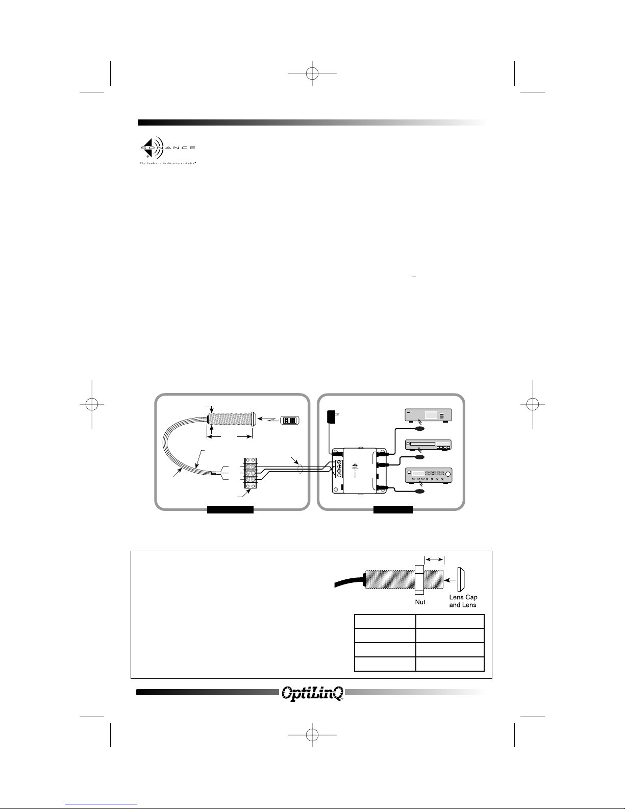
INSTALLATION
SMR1 is intended to be wired to the input terminals of Sonance Connecting Blocks or other devices, using
the supplied 3-terminal block in the remote room location. A 3-conductor cable (refer to specifications above)
is run to the main room. Connections are then made to a Sonance connecting block, power supply, and
emitters as shown in the following illustration of a typical basic system:
5/8"
TIME SAVING TIP
The threads on the chassis of the SMR1 and SMR1P are
coarse for ease of installation. To further save on
installation time, it is recommended that the lens cap is
removed and the nut is set to a predetemined length (see
table on right). Place the SMR1 or SMR1P into the
predrilled 1/2” diameter knockout in the speaker baffel.
Then reattach the lens cap (and lens) from the front. Twist
the tube counterclockwise in the nut to lock the SMR1 or
SMR1P in place. This can greatly ease installation and
save you time
.
SPEAKER TYPE PRESET LENGTH
C S
ERIES 5/8” (16.5MM)
S
YMPHONY 1/2” (12.7MM)
VIRTUOSO 5/8” (16.5MM)
SMR1 - Standard version, with brass bezel, and a 7 Foot three-conductor ribbon cable.
SMR1P - Same as SMR1 with a mini phone plug on the end of the cable.
SMR1insMan.qxd 12/20/02 5:25 PM Page 1
Pg 2
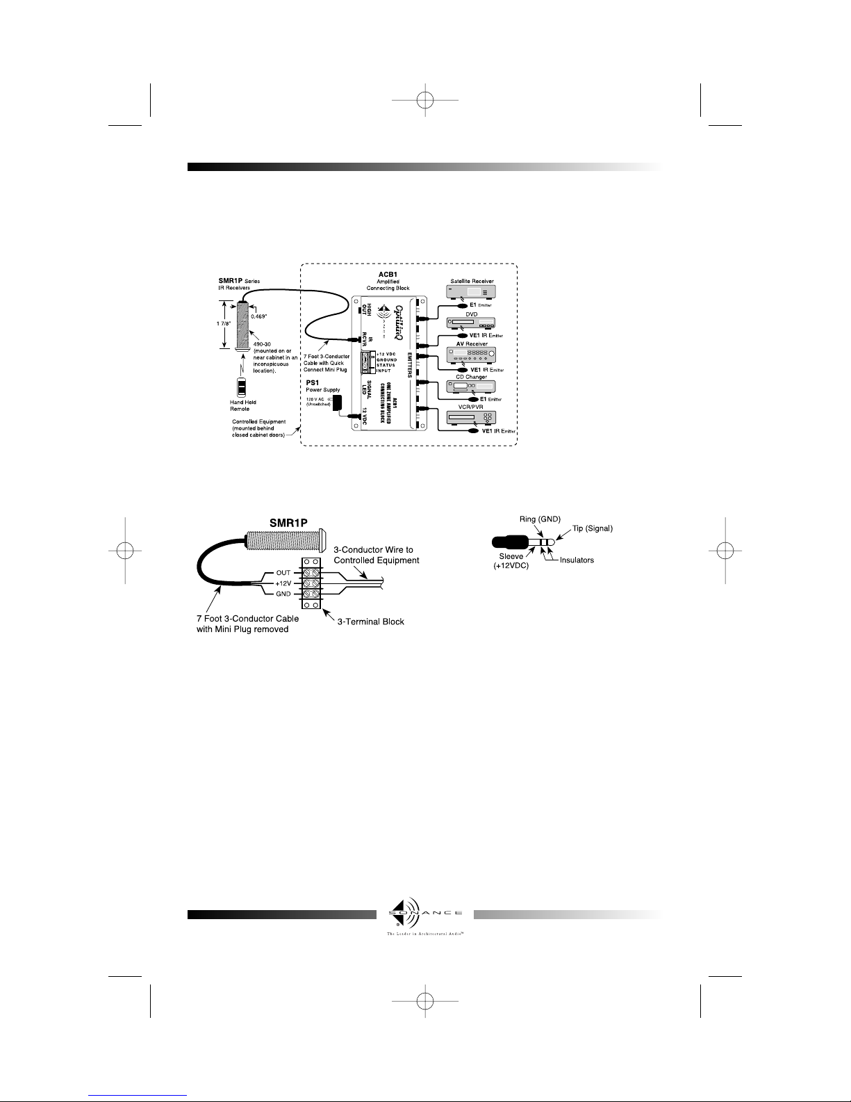
The SMR1P is the same as the SMR1 except it’s 7-foot cable is terminated with a 3.5 mm stereo type mini
plug. It plugs directly into the "IR RCVR" jack on Sonance Connecting Blocks, such as the CB1, CB2Z, ACB1,
etc. The SMR1P should be used in installations where the connecting block is within reach of the
7-foot cable -- such as when installing the SMR1P in a cabinet where the controlled equipment is behind
closed doors.
A typical system, with an SMR1P, PS1 Power Supply, and E1 Emitters plugged into an ACB1 Amplified
Connecting Block, is shown in the following diagram:
Mounting: Drill a 1/2”
hole in any flat surface,
such as a cabinet panel.
Pass the lead and the
body of the SMR1P
through the hole and
secure from the rear
with the nut (supplied).
Affix the Mini-Emitters,
such as the E1, E2, VE1,
and VE2 series, to the IR
sensor windows of the
controlled equipment in
accordance with the
instructions that come
with them.
SMR1P Cable Connections
The SMR1P may also be used where the 7-foot lead is not long enough. In this case, simply cut off the mini
plug, strip the leads, and connect them to a 3-terminal block in the same way as you would for the SMR1.
See product label for wire color code.
NOTE: With any of these systems, be sure the PS1
power supply is plugged into an un-switched AC
outlet. This maintains the SMR1/SMR1P system in
"standby" operation so that power-on commands
can be sent to the controlled equipment.
Stereo Mini Plug
OPTILINQ RECEIVER TROUBLE SHOOTING TIPS:
1. The most common problem encountered is stray IR or electronic interference or noise disrupting the IR signal from the
remote control preventing proper transmission to the source equipment.
Examples of such interference:
• Fluorescent, Halogen or Neon lights, and light dimmers.
• Direct or reflected sunlight.
• Electronic noise from tube or flat panel televisions.
• Infrared security sensors.
2. Determine possible sources of interference by turning off lights, TV sets, and alarm systems as well as isolating the receiver
from any sunlight. Then test the operation of the system.
• Sometimes interference will cause the talk-back LED to blink or illuminate dimly indicating noise entering the receiver.
• The talk-back LED should ONLY blink when IR commands are sent from a remote control to the receiver.
• When the source of interference is determined, it may be necessary to move either the source of the noise or the receiver
to achieve proper operation.
3. If the talk-back LED on the receiver does NOT blink when IR commands are sent from the control, check the following:
• Make sure the PS1 power supply is securely plugged into a live 120V AC wall outlet.
• Be sure that if you are using a receiver with a stereo mini plug that it is plugged into the IR RCVR jack and not any of the
EMMITER jacks.
• Check to see that all mini plugs are properly seated into the jacks and that the wires are securely attached to the screw header.
4. If using a VE1 or VE2 and it is flashing but the component is not responding, make sure that the emmiter is located directly
over the IR receiver of the component. Consult the owners manual of the component or the manufacturer if you are having
trouble locating the receiver.
5. If you continue to have problems with your OptiLinQ system, please call our Technical Assistance Department at:
(800) 582-0772 or (949) 492-7777 between 7 AM and 5 PM PST.
SONANCE • 212 Avenida Fabricante • San Clemente, CA 92672
www.sonance.com
SMR1insMan.qxd 12/20/02 5:25 PM Page 2
 Loading...